
INSTALLATION
DIFFICULTY:
INSTALLATION GUIDE
for the
SB-GM-HUMRH3/10W1v2
2005 - Up Hummer H3 SUV with the Monsoon® System.
Thank you for choosing a JL Audio Stealthbox
®
for your automotive sound system. With
proper installation, your new vehicle-specific enclosed subwoofer system will deliver years
of listening pleasure.
We strongly recommend that you have your new Stealthbox
®
installed by your authorized
JL Audio dealer. The installation professionals employed by your dealer have the necessary
tools and experience to disassemble and reassemble your vehicle properly. Also, keep in
mind that your warranty coverage extends to 2 year if your system is installed or approved
by your authorized JL Audio dealer. If you prefer to perform your own installation, please
read this installation guide completely before beginning the process.
If you choose to perform the installation yourself, it is absolutely vital that
the Stealthbox
®
be properly mounted to the vehicle according to these
instructions. Failure to mount the enclosure properly presents two problems:
1) The sub-bass performance will suffer due to the movement of the enclosure
caused by the force exerted by the woofer(s).
2) A loose enclosure presents a serious safety hazard in the event of a collision
or sudden deceleration.
STEP 1
Remove any contents from the rear cargo area and lower the
rear seats forward.
Continued on Next Page
STEP 2
The driver’s side rear plastic inner fender needs to be
removed.
Using a 10mm socket and ratchet, remove the 5 bolts.
Using a Phillip® head screw driver, remove the 2 screws.
STEP 3
Pop out the 5 plastic pop-rivets.
The plastic inner fender will drop down.
SB-GM-HUMRH3/10W1v2_ 011215
35
OUT
OF
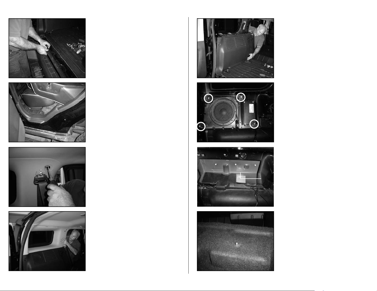
STEP 9
With a 10mm socket and ratchet, remove the four bolts that
hold the factory woofer system into place.
Unplug the amplifier and remove the woofer system out of
vehicle.
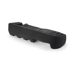
STEP 11
Thread in the supplied socket cup set screw into the thread-
ed insert, located on the bottom of the Stealthbox®.
Leaving 1/2-inch exposed.
STEP 10
After the factory woofer system has been removed, look
down into the cavity. There is a rubber matting that lays on
top of the wheel well. Cut the front half of this matting out.
Place the wax square to the proper measurements, 3" from
the side wall and 5-1/4-inch from the front wall.
Continued on Next Page
SB-GM-HUMRH3/10W1v2_ 011215
STEP 7
Remove the top panel.
STEP 6
With a Phillip® screw driver, remove the screw that is located
under the cover panel.
With a T-50 torx bit and ratchet, remove the seat belt loop.
STEP 5
At the driver’s side rear door, remove the door sill.
STEP 4
From the cargo entrance, remove the weather stripping.
Start at the lower middle. Pull off just past the driver side
paneling.
STEP 8
Remove the lower panel.
Page 2 • JL Audio, Inc 2005
51/4"
3"
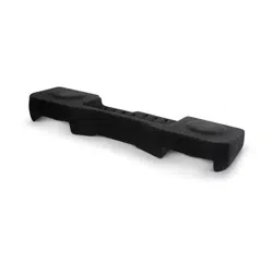
STEP 17
Apply the supplied double sided tape to the supplied foam
bar. Apply the foam bar to the back side of the lower cargo
panel that was removed in STEP 8. The foam needs to be
placed below the factory grille opening.
Secure this lower panel back into place.
STEP 19
With a Phillip® screw driver, remount the screw that removed
in STEP 6. Apply factory cover
With a T-50 torx bit and ratchet, secure the seat belt loop.
Apply factory cover.
STEP 18
Secure the upper panel back into place.
Continued on Next Page
SB-GM-HUMRH3/10W1v2_ 011215
STEP 15
From the outside driver's side rear wheel well; place the sup-
plied fender washer, flat washer, lock washer and then hex
nut onto the protruding socket cup set screw. Secure tightly
with a 14mm socket, long extension and ratchet.
Note: For added protection it is recommended that
you apply a bead of silicone between the vehicle and
the fender washer. After the bolt assembly is tightly
secured, it is also recommended that vehicle under-
coating material is applied to the exposed assembly.
STEP 14
Loosen the socket cup set screw to expose 1-inch. Place the
Stealthbox® into place, carefully guiding the socket cup set
screw through the drilled hole.
Using a supplied bolt and washer, secure the L-bracket to the
top of the enclosure.
(Disregard the woofer grille)
STEP 13
Using a factory bolt that was removed in STEP 9. Mount the
supplied L-bracket to the upper right threaded mounting
hole. One of the same holes that was used to mount the
factory woofer system to the vehicle.
The L-bracket needs be mounted with the protruding angle
to the top.
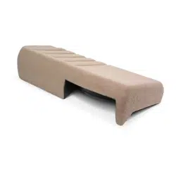
STEP 12
Position the Stealthbox® into place and press firmly down.
This is to make an impression onto the wax square.
Remove the Stealthbox®.
With a 1/2" drill bit or Step Bit/Unibit® and drill. Drill at the
impression on the wax square, through the floor to the
outside.
Remove the wax square.
(Disregard the woofer grille)
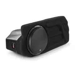
STEP 16
Run speaker wire from the amplifier location to the
Stealthbox® and attach to the terminal.
Check woofer for proper operation.
(Disregard the woofer grille)
Page 3 • JL Audio, Inc 2006
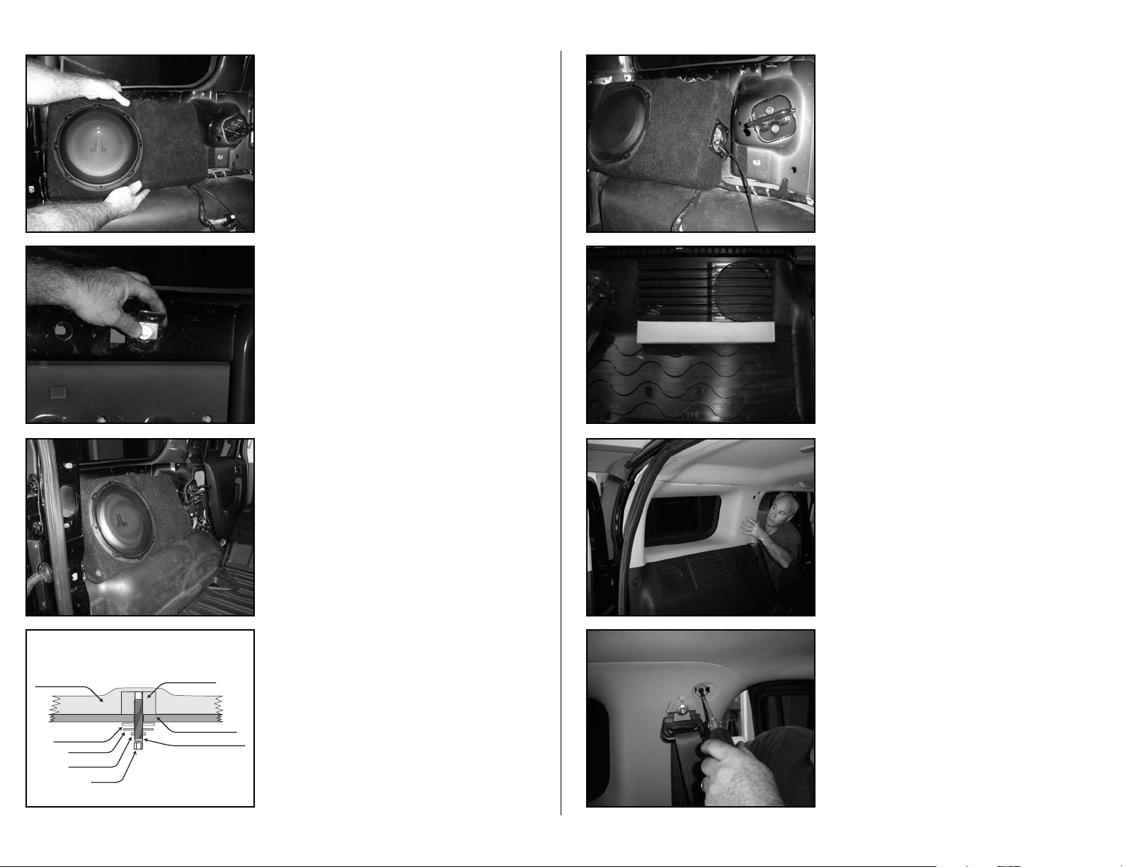
STEALTHBOX WALL
THREADED INSERT
VEHICLE SHEET METAL
FENDER WASHER
SOCKET CUP SET SCREW
LOCK WASHER
FLAT WASHER
HEX NUT
SB-GM-HUMRH3/10W1v2_ 011215
CONGRATULATIONS
You have completed the installation for this model!
Please refer to the Power Recommendation section for an
amplifier recommendation and basic set-up help.
STEP 22
Secure the driver’s side rear plastic inner fender.
Using a 10mm socket and ratchet, secure the 5 bolts.
Using a Phillip® head screw driver, secure the 2 screws
Pop in the 5 plastic pop-rivets.
STEP 21
From the cargo entrance, reapply the weather stripping.
STEP 20
Secure the driver’s side rear door sill.
Page 4 • JL Audio, Inc 2006
All specifications are subject to change without notice. “JL Audio®” and the JL Audio logo, “Stealthbox” and the Stealthbox logo are registered
trademarks of JL Audio, Inc. “Ahead of the Curve” and its respective logo is a trademark of JL Audio, Inc.
JLA-SKU#011215-08-23-2006 • Printed in USA • ©2006 JL Audio, Inc. • U.S. PATENTS: #5,734,734 #5,949,898 #6,118,884 #6,229,902
#6,243,479 #6,294,959 #6,501,844 #6,496,590 #6,441,685 #5,687,247 #6,219,431 #6,625,292 #D472,891 #D480,709 Other U.S. & Foreign
patents pending. For more detailed information please visit us online at www.jlaudio.com.
(954) 443-1100
www.jlaudio.com
10369 NORTH COMMERCE PARKWAY • MIRAMAR, FLORIDA • 33025 • USA
INCLUDED HARDWARE
(1) 13/8-inch - 16 x 2-1/4-inch Socket Cup Screw (1) 3/8-inch - 16 x 1-1/4-inch Hex Bolt
(1) 3/8-inch x 1-1/4-inch Fender Washer (1) L- Br ac ket
(2) 3/8-inch x 3/4-inch USS Flat Washer (1) Foam Bar
(2) 3/8-inch Lock Washer (1) Double Sided Tape
(1) 3-inch x 3-inch Wax Square
SPECIFICATIONS
Enclosure Type: Acoustic Suspension (sealed)
Driver Type: 10W1v2-4
Nominal Impedance: 4 ohms mono
Continuous Power Handling: 150 Wat ts
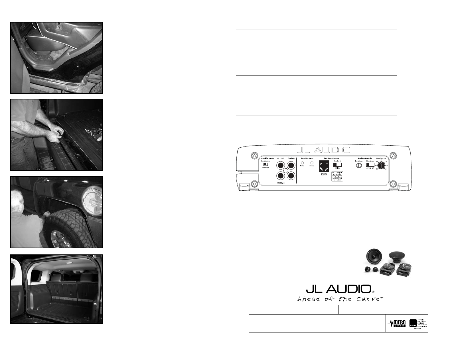
POWER RECOMMENDATION
JL Audio recommends using a high quality amplifier such as the JL Audio a2150.
The diagram below shows the recommended crossover, infrasonic filter and equalizer settings for the a2150 when
being used to power your Stealthbox
®
.
The JL Audio a2150 is a very versatile audio component. Please consult the owner’s manual for even more
detailed information about installing and tuning this amplifier.
MID/HIGH FREQUENCY DRIVER FITMENT
A variety of JL Audio coaxial and component systems will fit in the factory speaker locations of you vehicle.
Front Speaker Size / Location: 6.5-inch / Front Doors
Fits JL Audio Models: TR650-CXi, VR650-CSi, VR650-CXi, XR650-CSi, XR650-CXi & ZR650-CSi
Rear Speaker Size / Location: 6.5-inch / Rear Doors
Fits JL Audio Models: TR650-CXi, VR650-CXi & XR650-CXi