
INSTALLATION GUIDE
for the
SB-F-150-SPRCRW/13TW5v2
SKU# 94460-94462
2009-Up Ford F-150 SuperCrew & 2017-Up Ford SuperDuty Crew Cab
Thank you for choosing a JL Audio Stealthbox® for your automotive sound system.
With proper installation, your new vehicle-specific enclosed subwoofer system
will deliver years of listening pleasure.
We strongly recommend that you have your new Stealthbox® installed by your
authorized JL Audio dealer. The installation professionals employed by your
dealer have the necessary tools and experience to disassemble and reassemble
your vehicle properly. If you prefer to perform your own installation, please read
this installation guide completely before beginning the process.
If you choose to perform the installation yourself, it is absolutely
vital that the Stealthbox
®
be properly mounted to the vehicle
according to these instructions. Failure to mount the enclosure
properly presents two problems:
1) The sub-bass performance will suffer due to the movement of the
enclosure caused by the force exerted by the woofer(s).
2) A loose enclosure presents a serious safety hazard in the event of a
collision or sudden deceleration.
INSTALLATION
DIFFI CULT Y:
ESTIMATED TIME:
1-2 HOURS
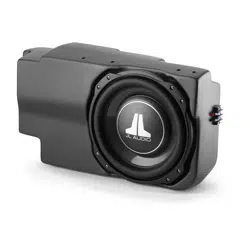
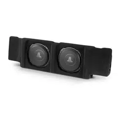
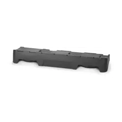
Enclosure Type: Sealed
Driver Type: 13T W5v2
Nominal Impedance: 2 ohms
Continuous Power Handling: 600 watts (RMS method)
Continued on Next Page
2
5
OUT
OF
SB-F-SPRCRW/13TW5v2 INSTR_SKU# 011297
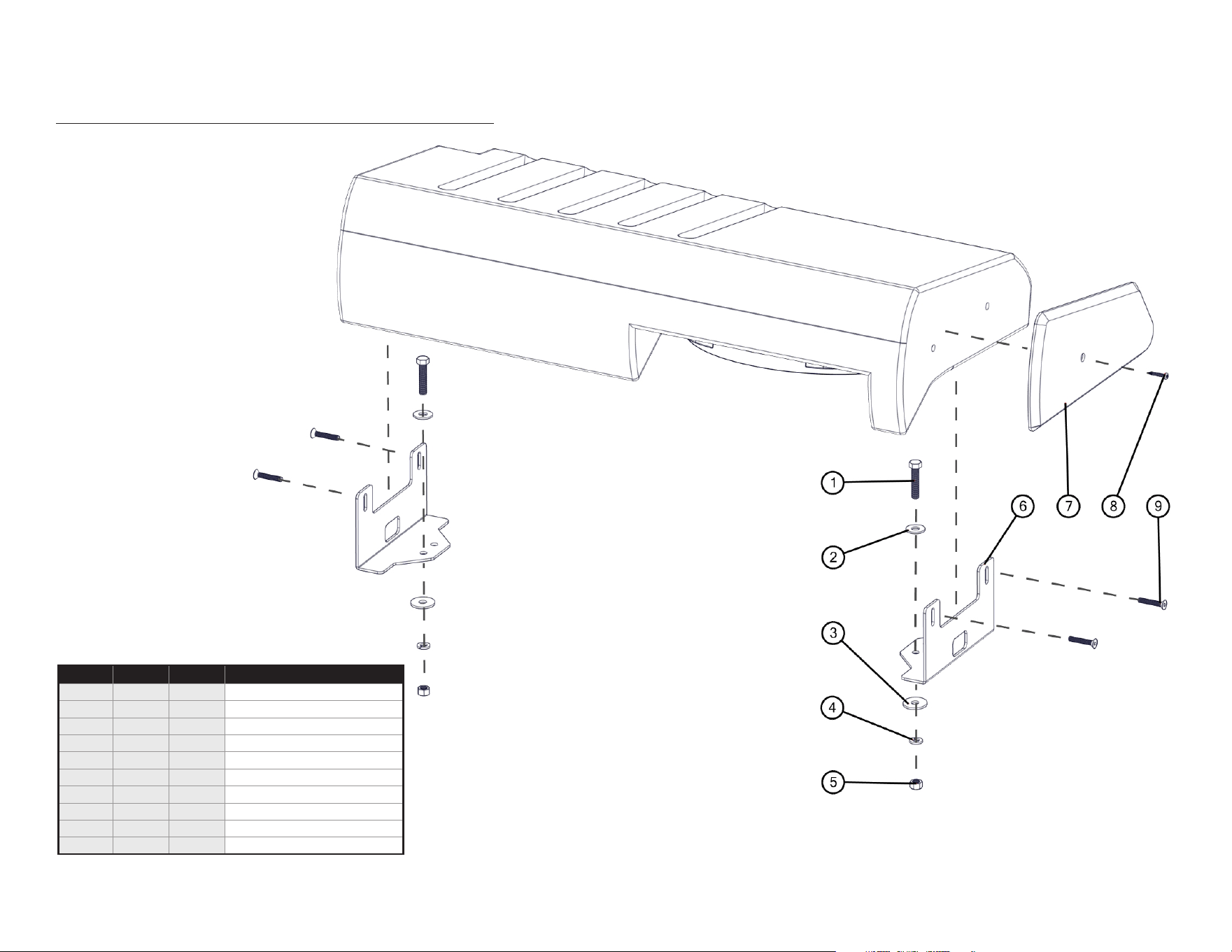
INCLUDED HARDWARE
Continued on Next Page
Page 2 • JL Audio, Inc., 2017
SB-F-SPRCRW/13TW5v2 INSTR_SKU# 011297
BOM ID Qty SKU Description
1 2 151087 3/8 - 16 x 1-3/4” Hex Bolt
2 2 151095
3/8” Flat Washer
3 2 151126 3/8” Fender Washer
4 2 151081 3/8” Split Lock Washer
5 2 151406 3/8 - 16 Hex Nut
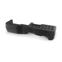
6 2 153865 Bracket
7 1 150570 Trim Panel
8 1 150295 #8 x 1” Self Tap Screw
9 4 150072 1/4 - 20 x 1-1/2” Hex Drive Bolt
- 2 151345 Wax Square (not shown)
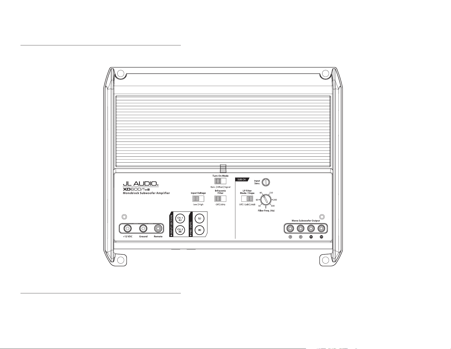
POWER RECOMMENDATION
JL Audio recommends high quality ampliers such as the JL Audio XD600/1v2. The diagram below shows the recommended crossover settings for the XD600/1v2. For a detailed description of the
amplier settings, consult the owner’s manual for the amplier. If another amplier is being used, please reference this illustration and use similar settings on that amplier.
CONNECTIONS
Using quality power, signal, and speaker wire is essential in ensuring the performance of your Stealthbox®. JL Audio recommends using a 4 AWG power kit such as the XD-PCS4-1B for your
Stealthbox® amplier. Other kits are available should you be using more than one amplier. Signal wire such as the JL Audio Premium Audio Interconnect Cables should be used to provide signal for
both channels of the amplier. JL Audio recommends using 12 AWG speaker wire for subwoofers such as our XC-BCS12-25.
Continued on Next Page
Page 3 • JL Audio, Inc., 2017
SB-F-SPRCRW/13TW5v2 INSTR_SKU# 011297
Page 4 • JL Audio, Inc., 2017 Continued on Next Page
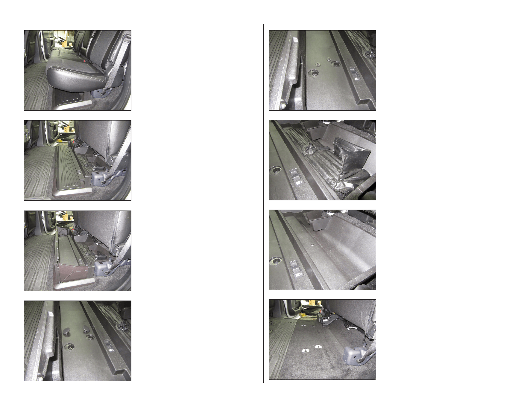
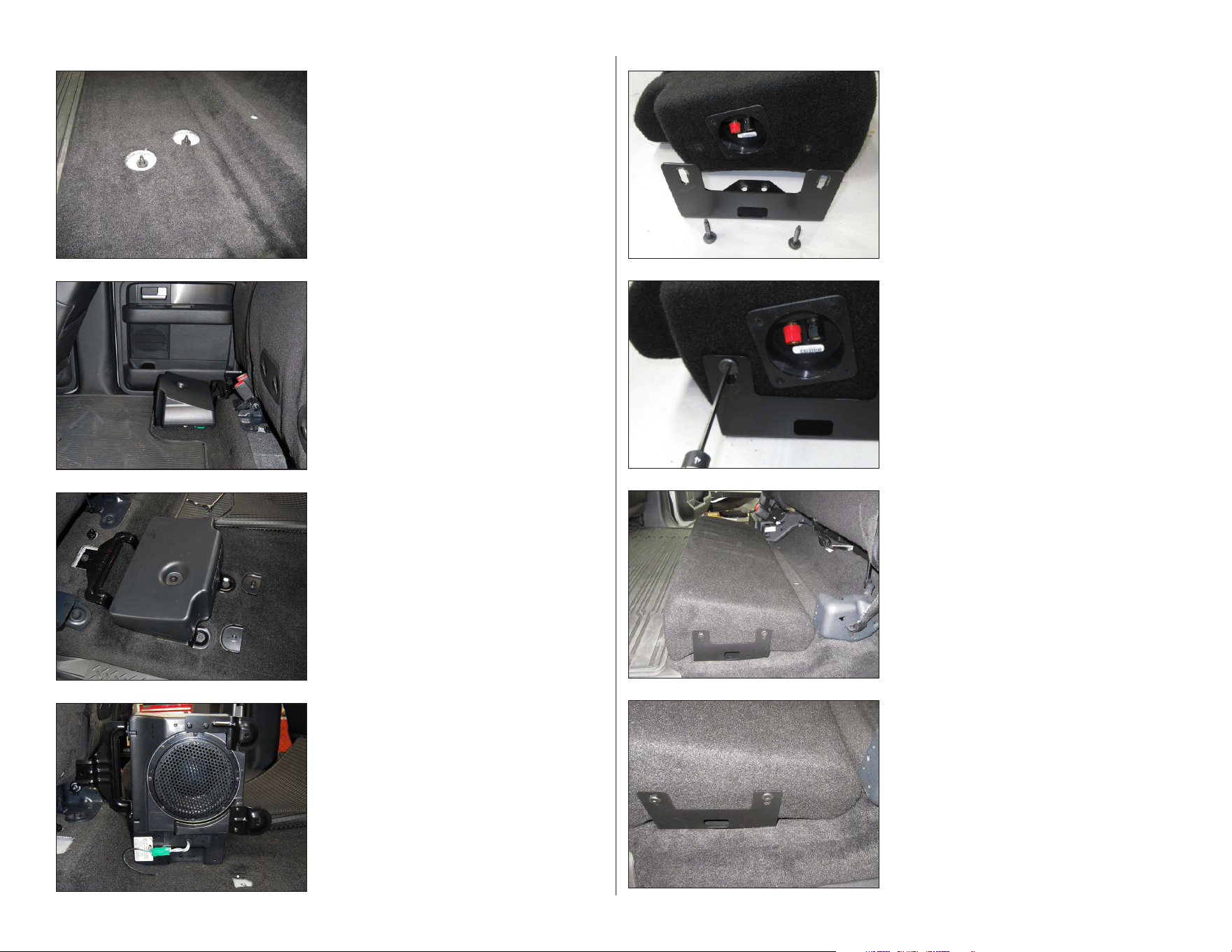
STEP 8
Remove the plastic storage tray from the
vehicle.
STEP 7
Remove the jack tools from the vehicle.
STEP 6
Unscrew the wing nut securing the jack tools.
STEP 5
Remove the two factory nuts from each side of
the tray.
STEP 4
Remove the two cover panels from each side of
the tray to expose the factory nuts.
STEP 3
Note: Steps 3-9 are for vehicles equipped with
the pictured plastic storage tray. For vehicles
without the tray, skip to Step 10.
Fold open the plastic storage tray.
STEP 2
Lift the rear seat.
STEP 1
Empty the rear seat area.
SB-F-SPRCRW/13TW5v2 INSTR_SKU# 011297
Page 5 • JL Audio, Inc., 2017 Continued on Next Page
STEP 16
Align the Bracket with the raised edge of the
floor on the driver’s side, as shown.
Slide a Wax Square under each of the Brackets,
centering them with the forward hole in the
Bracket.
STEP 15
Place the Stealthbox® into the vehicle, as
shown.
STEP 14
Thread a 1/4 - 20 x 1-1/2” Hex Drive Bolt
through each of the slots in the Bracket, into
the threaded inserts on the enclosure. With the
1/4 - 20 x 1-1/2” Hex Drive Bolts positioned at
the top of each slot, fully tighten both bolts.
Repeat the process for the opposite side.
STEP 13
Align a Bracket to each end of the Stealthbox®
as shown.
STEP 12
Unplug and remove the enclosure from the
vehicle.
ST E P 11
Unclip and remove the three bolt covers, and
remove the three bolts securing the factory
subwoofer enclosure.
STEP 10
Note: Steps 10-12 are for F-150 vehicles
equipped with the pictured factory subwoofer
enclosure only. For all other vehicles, skip to
Step 13.
STEP 9
Reinstall the factory nuts on the studs, and
fully tighten.
SB-F-SPRCRW/13TW5v2 INSTR_SKU# 011297
Page 6 • JL Audio, Inc., 2017 Continued on Next Page
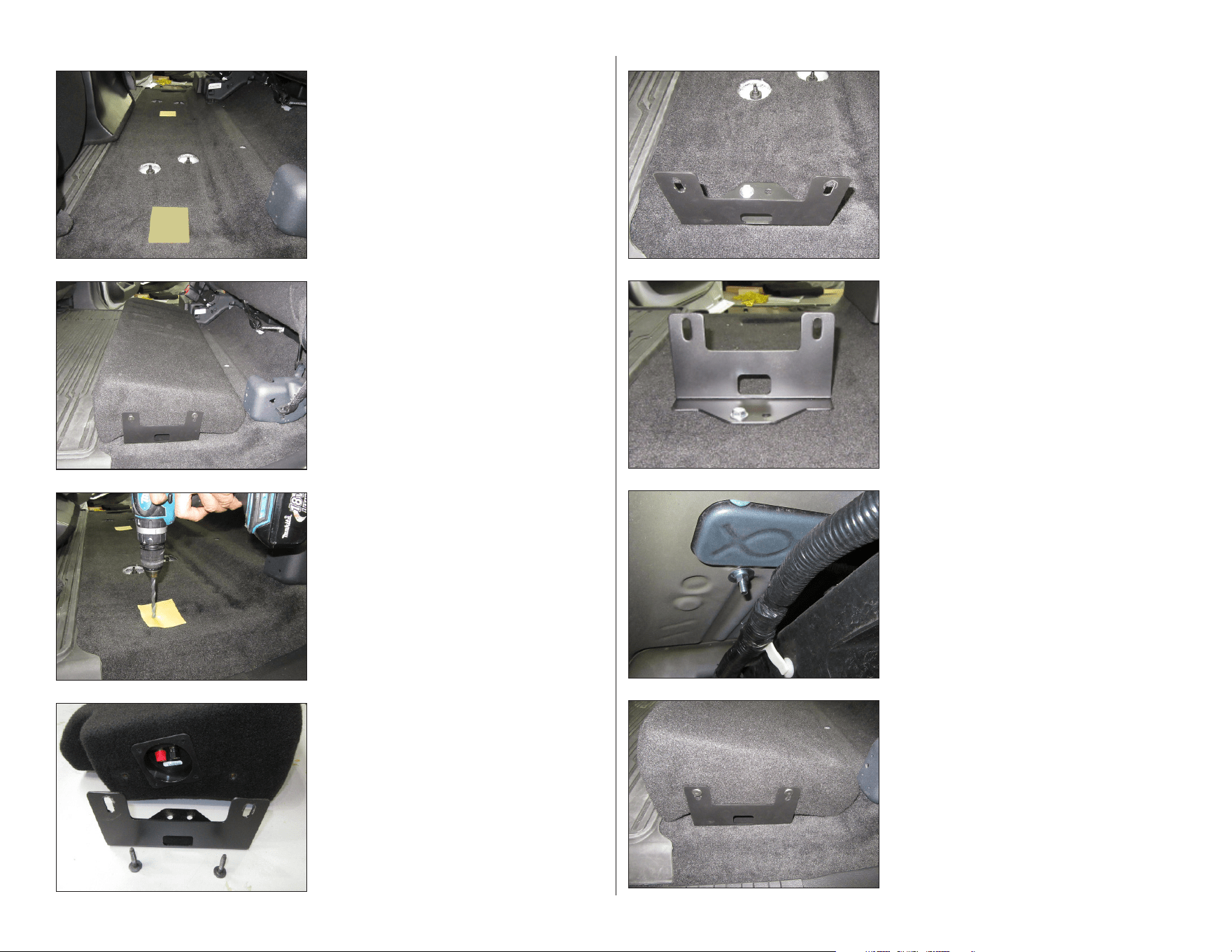
STEP 24
Reinstall the Stealthbox®. Reinstall the two 1/4
- 20 x 1-1/2” Hex Drive Bolts through the slots
in each Bracket, into the threaded holes in each
side of the enclosure, and fully tighten while
pressing down on the enclosure.
STEP 23
From under the vehicle, slide a 3/8” Fender
Washer, a 3/8” Split Lock Washer, and a 3/8 - 16
Hex Nut over each of the 3/8 - 16 x 1-3/4” Hex
Bolts, and fully tighten.
STEP 22
Repeat the process for the opposite side.
STEP 21
Align the forward hole in a Bracket with one
of the drilled holes in the floor, as shown. Slide
a 3/8” Flat Washer over a 3/8 - 16 x 1-3/4” Hex
Bolt, and slide the bolt through the forward
hole in the Bracket and the hole in the floor.
STEP 20
Remove the Bracket from each side of the
Stealthbox®.
STEP 19
Remove the Stealthbox® once more. Using a
3/8” drill bit, carefully drill through the carpet
and floor at each Wax Square mark made in the
previous step. Remove the Wax Squares.
STEP 18
Carefully reinstall the Stealthbox®, and mark
the locations of each of the forward holes on
the Wax Squares using a pick tool or similar.
STEP 17
Carefully remove the Stealthbox® from the
vehicle without moving the two Wax Squares.
Remove the adhesive backing from each Wax
Square, and adhere them to the floor of the
vehicle.
SB-F-SPRCRW/13TW5v2 INSTR_SKU# 011297
Page 7 • JL Audio, Inc., 2017
MID/HIGH FREQUENCY DRIVER FITMENT
A variety of JL Audio coaxial and component systems will t in the factory speaker locations of your vehicle.
All specifications are subject to change without notice. “JL Audio®” and the JL Audio logo, “Stealthbox®” and the Stealthbox logo, and “How we play®” are registered trademarks of JL Audio, Inc.
“Ahead of the Curve” and its respective logo are trademarks of JL Audio, Inc.
Printed in USA • ©2017 JL Audio, Inc. • For more detailed information please visit us online at www.jlaudio.com.
(954) 443-1100
www.jlaudio.com
JLA-SKU# 011297 • ver. 03.22.2017 • 10369 NORTH COMMERCE PARKWAY • MIRAMAR, FLORIDA • 33025 • USA
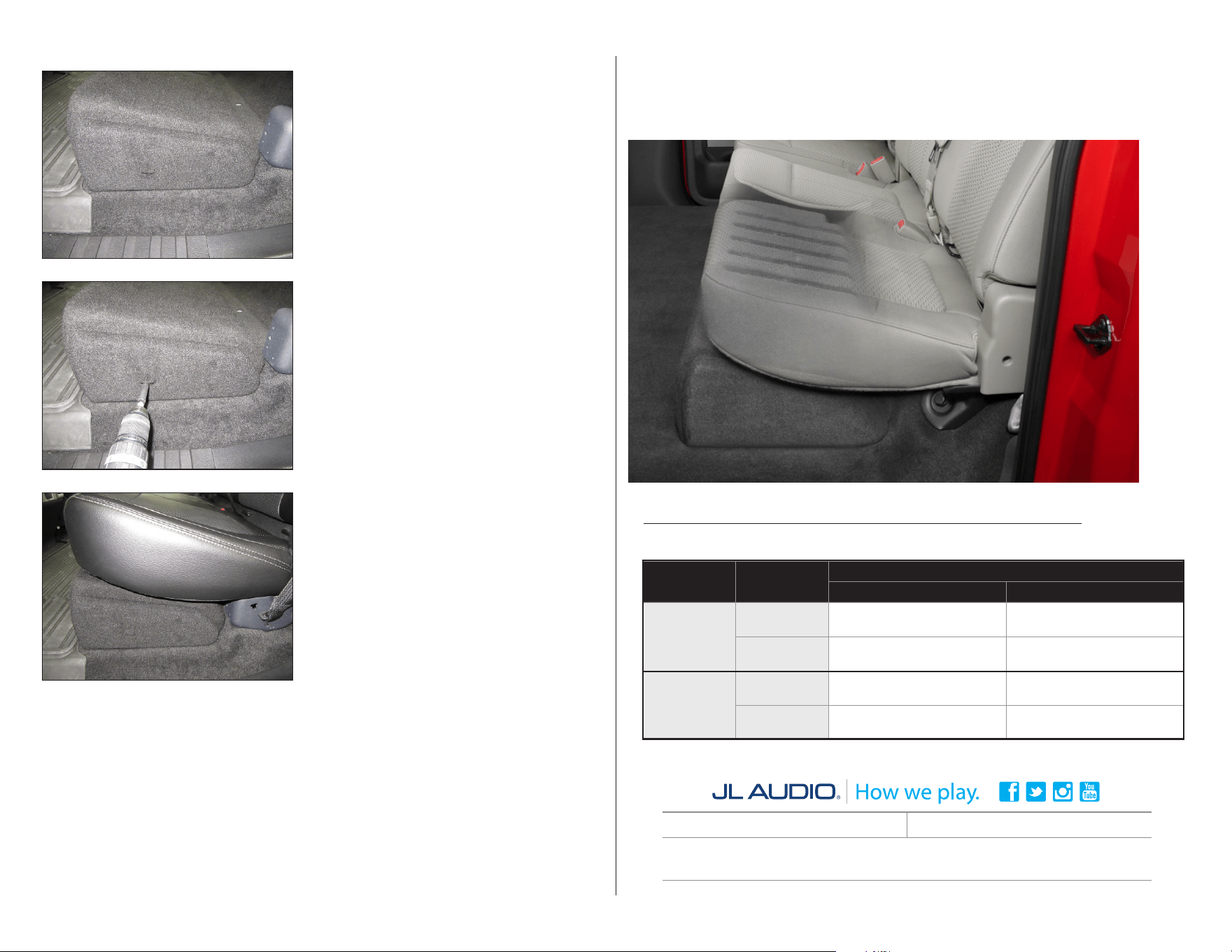
CONGRATULATIONS!
You have completed the installation for this model! Enjoy your new Stealthbox®!
SB-F-SPRCRW/13TW5v2 INSTR_SKU# 011297
Vehicle
Location /
OEM
Suggested JL Audio Speaker Models
Coaxial Models Component Models
‘09-’14 F-150
Front Doors /
6 x 8-inch
C1-570x, C2-570x, C5-570x C3-570, C5-570
Rear Doors /
6 x 8-inch
C1-570x, C2-570x, C5-570x C3-570, C5-570
‘15-Up F-150
&
‘17-Up
SuperDuty
Front Doors /
6 x 9-inch
C1-690x, C1-690tx, C2-690tx,
C5-650x
(1)
C1-690, C3-650
(1)
, C5-650
(1)
,
C7-650cw
(1,2)
Rear Doors /
6.5-inch
C1-650x, C2-650x, C5-650x
C1-650, C2-650, C3-650,
C5-650, C7-650cw
(2)
1 - Installation may require adaptor, 2 - Component woofer only
®
STEP 27
Connect speaker cable to the terminal cup on
the side of the Stealthbox®, and route the cable
as necessary.
Replace the jack tools, if desired, and fold the
rear seats back down.
STEP 26
Lift the carpet flap to access the hole in the
Trim Panel. Using a 1/8” drill bit, drill through
the hole in the Trim Panel and into the
Stealthbox®.
Secure the Trim Panel with a #8 x 1” Self Tap
Screw, as shown.
STEP 25
Align the Trim Panel with the driver’s side of
the enclosure, as shown.