Loading ...
Loading ...
Loading ...
15
MI254 Channel Operation Functions
LED COLOR
Functional Status
LED not
Illuminated
Indicates when the Channel is OFF
Green
Indicates when the Channel is ON with an
Audio Signal Present and Normal Operation for
the Channel exists
Amber
Indicates when maximum Power Output for the
Channel has occured with prevention of Audio
Clipping
Red
Indicates current limit or short circuit for the
Channel Loudspeaker Output Connection
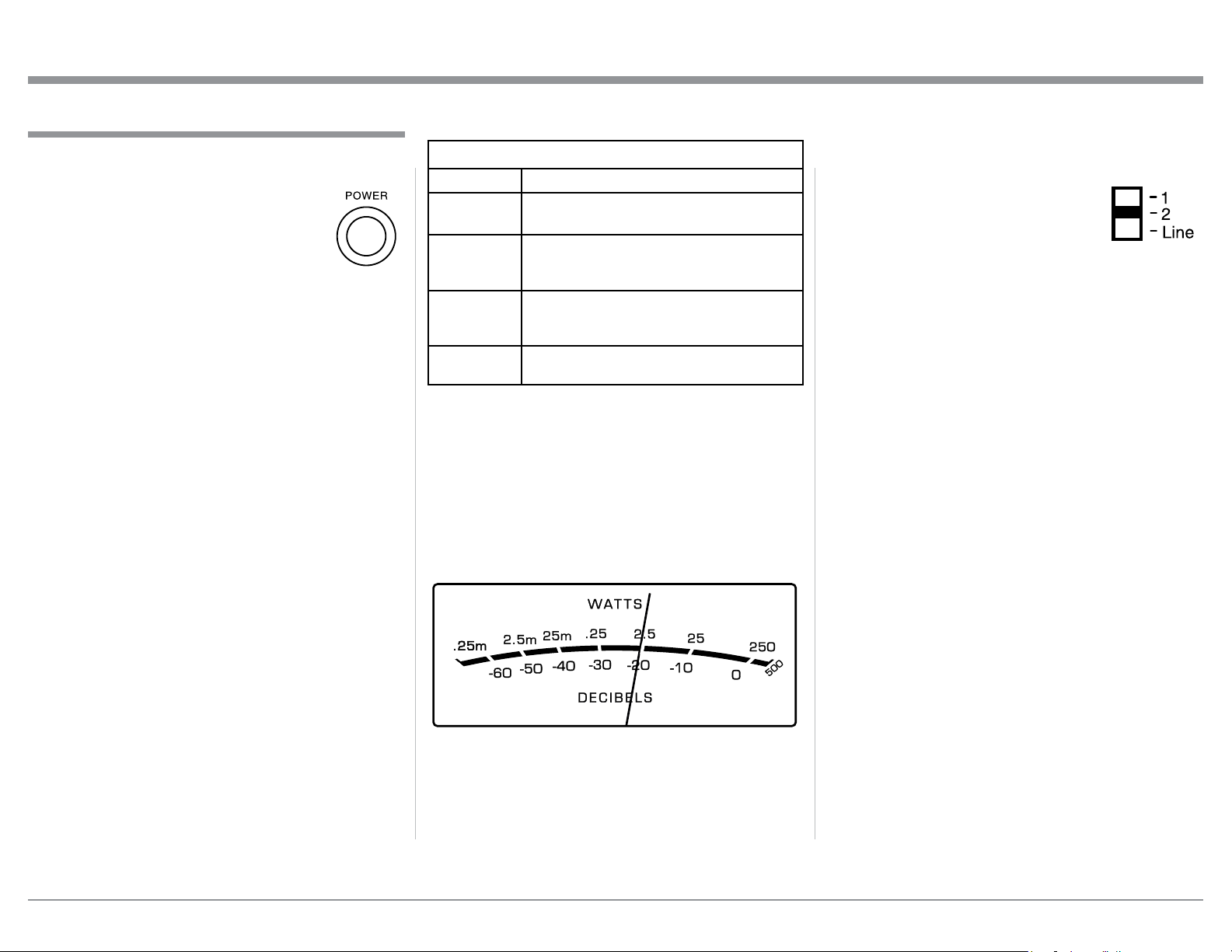
Power Output Meters
Both of the MI254 Power Output Meters indicate two
Amplifier Channels Outputs at the same time. The
Right Meter indicates Channels 3/R and 4/L. The Left
Meter indicates Channels 1/R and 2/L.
The MI254 Power Output Meters indicate the power
delivered to the Loudspeakers. Refer to figure 21.
The meters respond to all the musical information
being produced by the Amplifier. They indicate to an
accuracy of at least 95% of the power output with only
a single cycle of a 2,000Hz tone burst.
Power On
The LED STANDBY/ON Indicator illuminates to
indicate the MI254 is connected to AC
Power. To switch ON the MI254, press
the POWER Push-button on the Front
Panel or switch On the Audio Source
Component providing there is a Power
Control Cable Connection to the MI254.
Refer to figure 20.
Notes: 1. It will take about 6 seconds for initialization
of the internal circuitry to take place on the
MI254 when switched On.
2. There must be a power control connection
between the MI254 and the Audio Source
Component in order for the Remote Control
Operation Power ON/OFF to function.
3. When the MI254 is receiving a Power Control
ON Signal, the Front Panel POWER Push-
Button becomes inactive.
Auto Off Function
The MI254 incorporates Power Save Circuitry to
automatically place the MI254 into the power saving
Standby Mode approximately 30 minutes after there
has been an absence of an audio input signal on all
four channels.
When there is a Power Control Connection be-
tween the MI254 and a Preamplifier or Source Com-
ponent, the AUTO OFF Function is bypassed.
Channel Operational Indication
The MI254 Front Panel has four LEDs. The LEDs
indicate the current functioning status for each of the
four channels.
How to Operate
How to Operate
Figure 20
Figure 21
Input Selector
Each of the four Power Amplifier Channels have a
switch located on the rear panel for
selection of the Input Source Signal.
Refer to figure 22.
The Switch Position 1 is the Input
Signal Source from the BUS 1 UN-
BALance Input Jacks (Left or Right Channel feed the
same Power Amplifier Channel Type). The Switch
Position 2 is the Input Signal Source from the BUS 2
unbalanced Input Jacks (Left or Right Channel feed
the same Power Amplifier Channel Type).
The Switch Position LINE is the Input Signal Source
from the UNBALanced or BALanced Rear Panel
Connectors for the same Channel where the switch is
located. Refer to pages 6 and 7 for additional informa-
tion.
Figure 22
Loading ...
Loading ...
Loading ...