A30
A50

2
3 ENGLISH
10 FRANÇAIS
17 ESPAÑOL

3
WARNING!
There are several areas during the assembly process that special
attention must be paid. It is very important to follow the assembly
instructions correctly and to make sure all parts are rmly tightened. If
the assembly instructions are not followed correctly, the equipment could
have parts that are not tightened and will seem loose and may cause
irritating noises. To prevent damage to the equipment, the assembly
instructions must be reviewed and corrective actions should be taken.
PARTS INCLUDED:
F 1 Ascent Trainer Frame
F 1 Top Rail Bracket
F 2 Hand Rail Covers
F 1 Pedal Arm Cover Set
F 1 Upper Assembly
F 2 Incline Frame Boots
F 1 Top Cap Front Cover
F 1 Top Cap Rear Cover
F 2 Upper/lower Dual Action Arms
F 2 Link Arm Cover Sets
F 2 Handlebar Caps
F 1 Power Cord
F 1 Hardware Kit
Console sold separately
ASSEMBLY
Before proceeding, nd your ascent trainer’s serial number located on a barcode
sticker and enter it in the space provided below.
SERIAL NUMBER
MODEL NAME
F A30 F A50 MATRIX ASCENT TRAINER
* Use the information above when calling for service.
SERIAL NUMBER LOCATION
UNPACKING
Unpack the equipment where you
will be using it. Place the carton on a
level at surface. It is recommended
that you leave the frame in the
Styrofoam base until instructed. Never
open box when it is on its side.
NEED HELP?
If you have questions or if there are any missing parts, contact Customer Tech
Support. Contact information is located on the information card.
IMPORTANT NOTES
During each assembly step, ensure that ALL nuts
and bolts are in place and partially threaded.
Several parts have been pre-lubricated to aid in assembly
and usage. Please do not wipe this off. If you have diculty,
a light application of lithium grease is recommended.
TOOLS INCLUDED:
F 6 mm Allen Wrench
F 8 mm Allen Wrench
F 10 mm Allen Wrench
F 13/17 mm Flat Wrench
F Phillips Screwdriver
ENGLISH
4
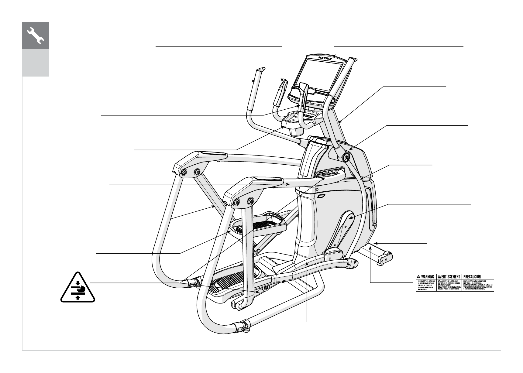
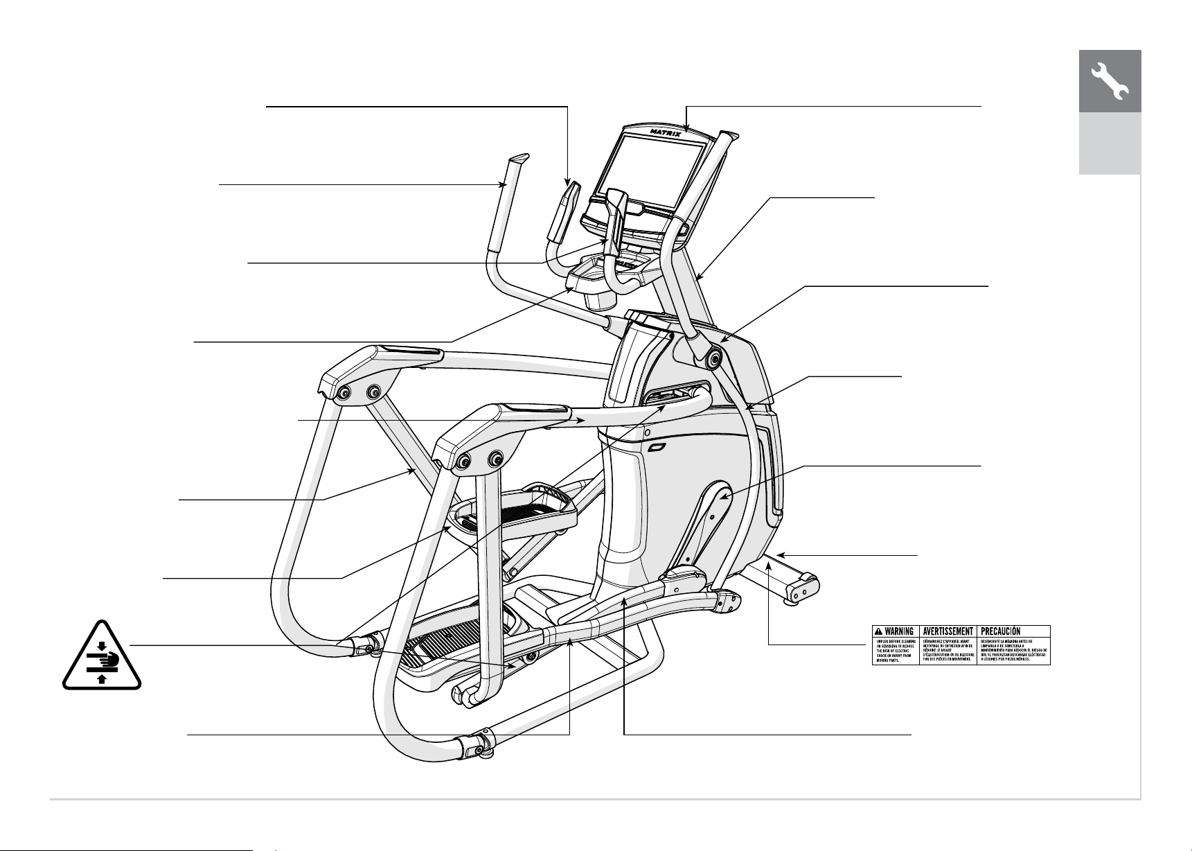
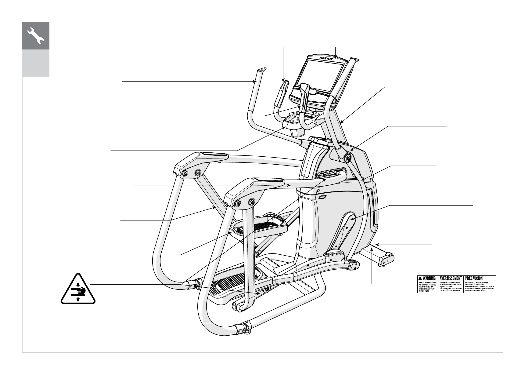
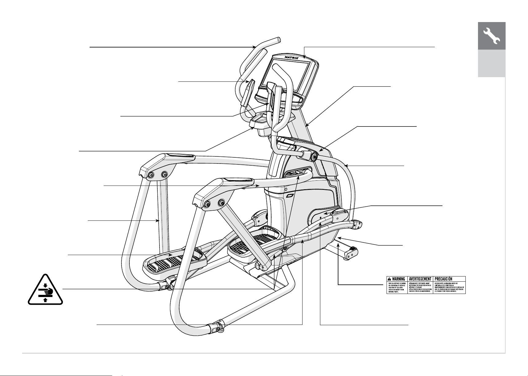
CONSOLE
CONSOLE MAST
TOP CAP
LOWER HANDLEBAR
CRANK
POWER CORD SOCKET
PEDAL ARM
RESISTANCE/INCLINE TOGGLES
UPPER HANDLEBAR
PULSE GRIPS
WATER BOTTLE HOLDER
TOP HAND RAIL
SWING ARM
FOOT PADS
LINK ARM
A30
ENGLISH

5
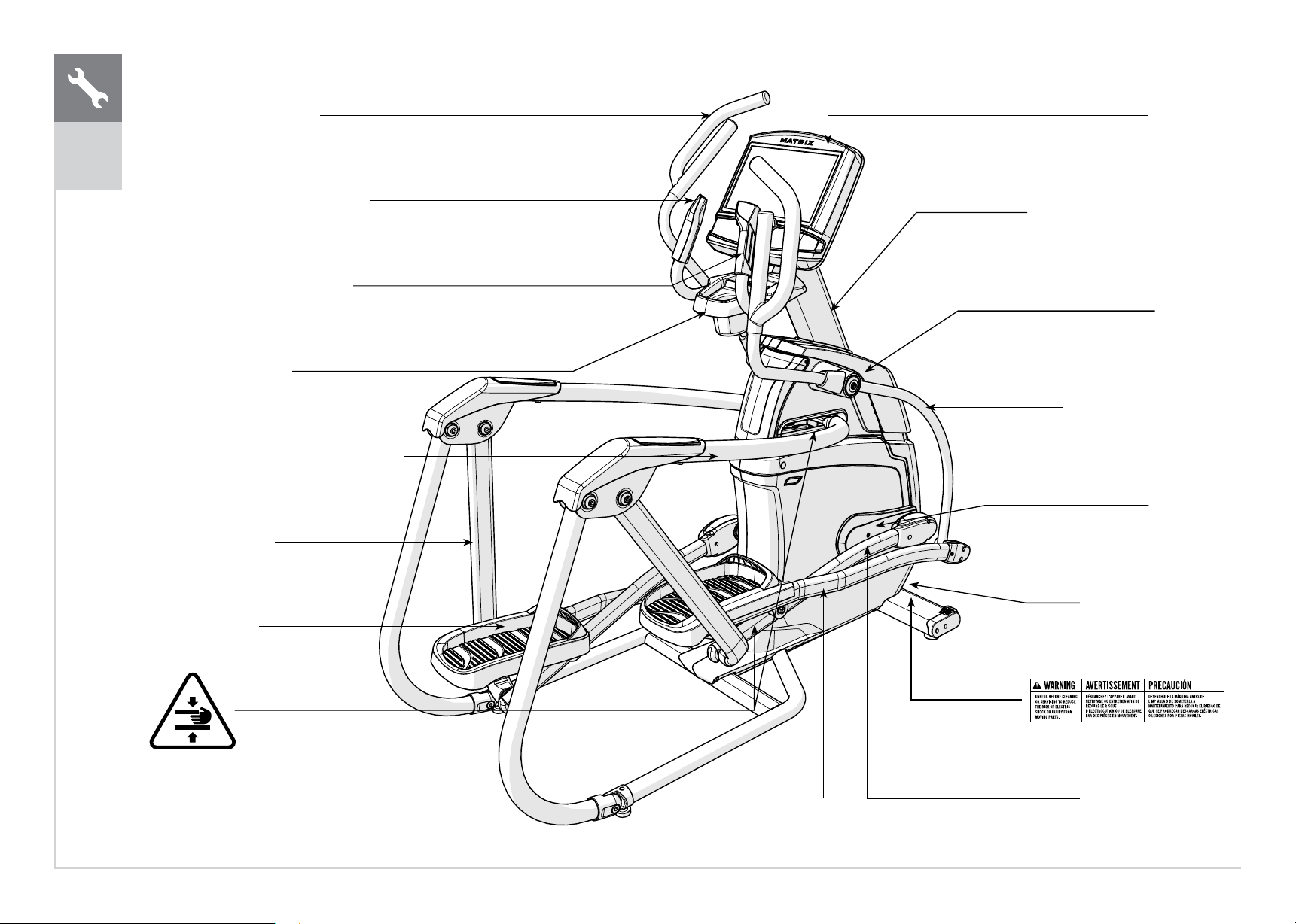
UPPER HANDLEBAR
RESISTANCE/INCLINE TOGGLES
PULSE GRIPS
WATER BOTTLE HOLDER
TOP HAND RAIL
SWING ARM
FOOT PADS
LINK ARM
CONSOLE
CONSOLE MAST
TOP CAP
LOWER HANDLEBAR
CRANK
POWER CORD SOCKET
PEDAL ARM
A50
ENGLISH
6
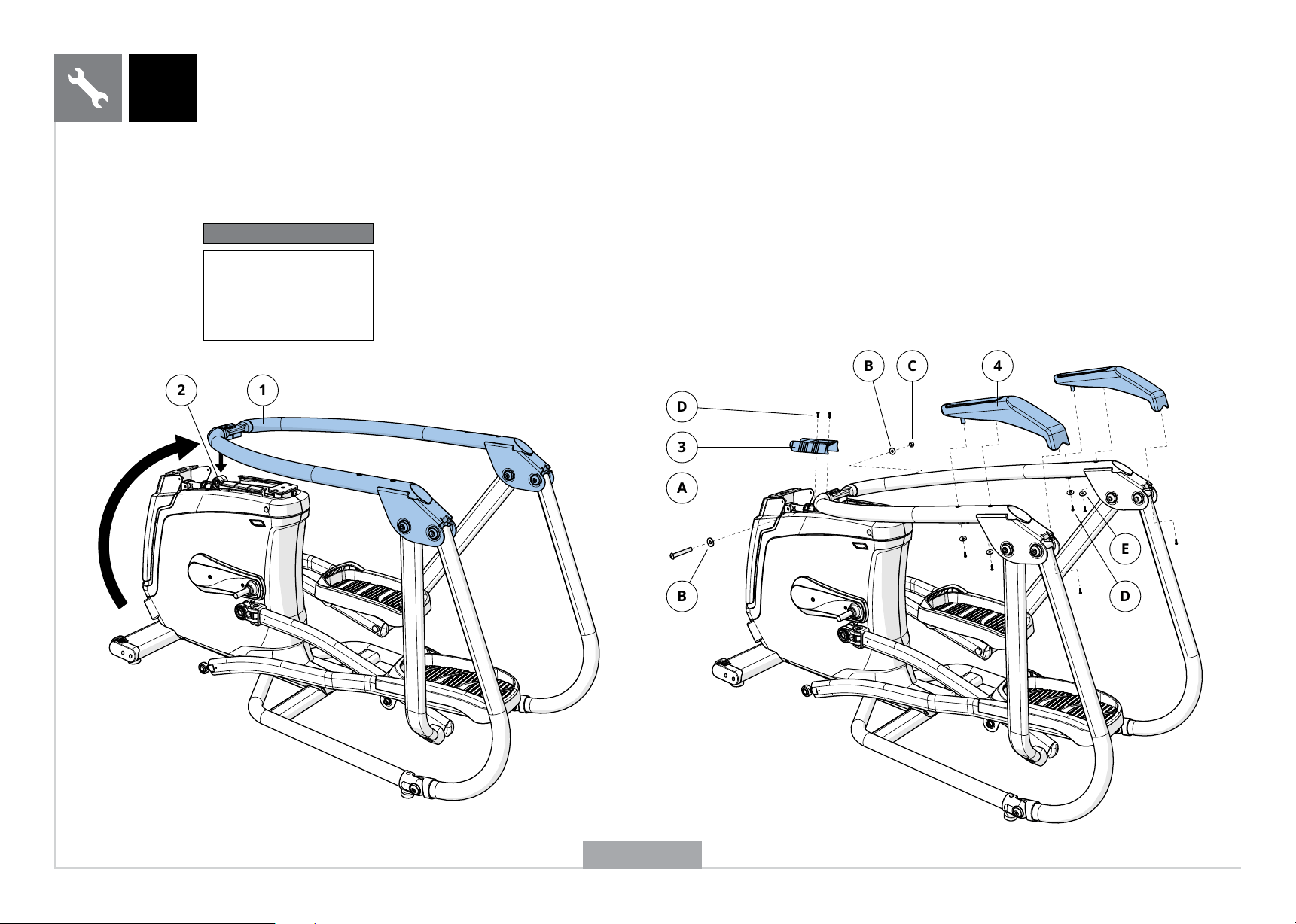
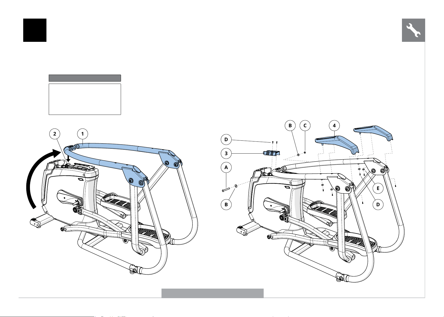
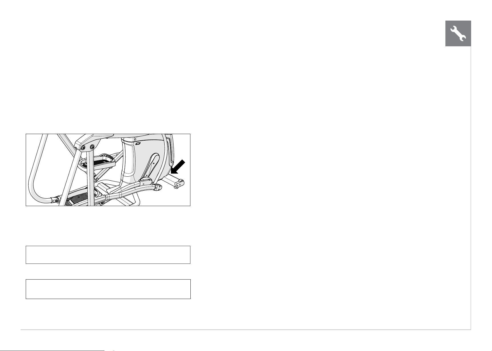
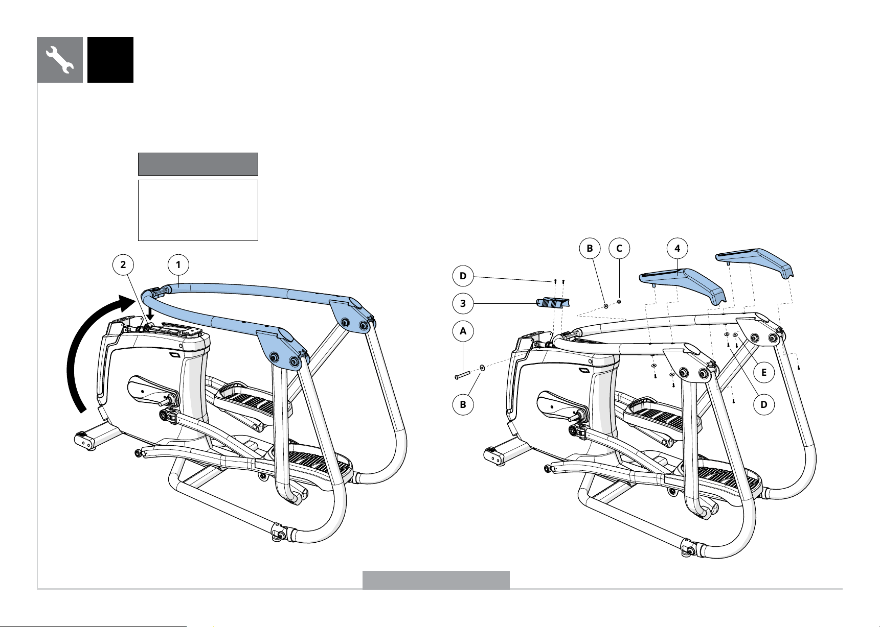
A Open HARDWARE FOR STEP 1.
B Gently lift up top HAND RAIL (1) and align with MAIN FRAME (2).
C Remove the wire tie from the MAIN FRAME (2).
D Attach TOP HAND RAIL (1) to MAIN FRAME (2) using 1 BOLT (A), 2 flat
WASHERS (B), and 1 NUT (C) and tighten to 45.9 Nm / 33.9 lb-ft.
E Attach TOP RAIL BRACKET (3) to TOP HAND RAIL (1) using 2 SCREWS (D).
F Attach HAND RAIL COVERS (4) using 6 SCREWS (D) and 4 FLAT WASHERS (E).
1
2
1
C
4
B
3
D
A
B
E
D
A50 SHOWN
Hardware For Step 1
Description Qty
A
B
C
D
E
Bolt
Flat Washer
Nut
Screw
Flat Washer
1
2
1
8
4
ENGLISH
7
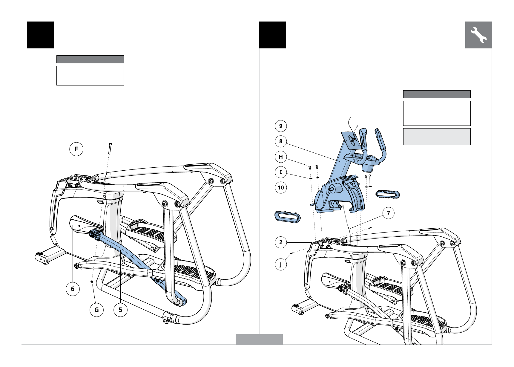
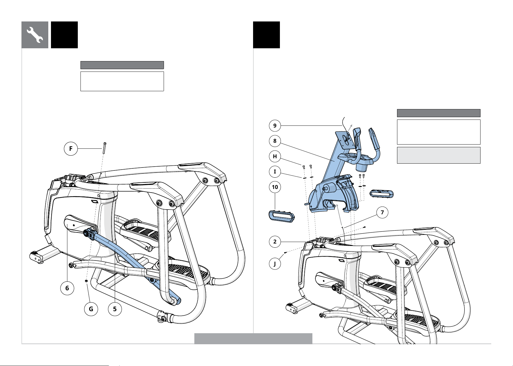
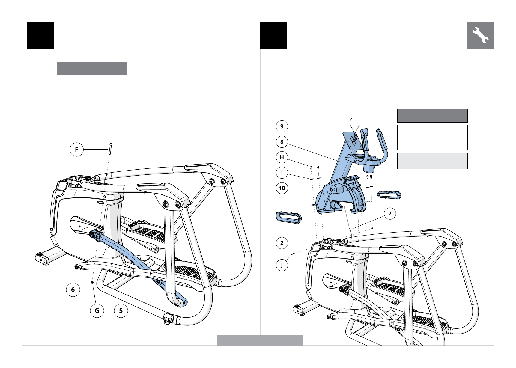
A Open HARDWARE FOR STEP 2.
B Slide LEFT PEDAL ARM (5) onto CRANK (6) and attach using
1 BOLT (F) and 1 NUT (G) and tighten to 77.4 Nm / 57 lb-ft.
6
F
G
5
2 3
Hardware For Step 2
Description Qty
F
G
Bolt
Nut
1
1
9
8
H
I
10
2
J
7
A Open HARDWARE FOR STEP 3.
B Carefully pull the CABLE (7) through the UPPER ASSEMBLY (8)
using the LEAD WIRE (9) located inside the UPPER ASSEMBLY (8).
C Attach UPPER ASSEMBLY (8) to MAIN FRAME (2) using 4 BOLTS
(H) and 4 FLAT WASHERS (I) and tighten to 64.5 Nm / 47.6 lb-ft.
D Insert 2 SCREWS (J) into bottom rear of MAIN FRAME (2).
E Insert INCLINE FRAME BOOTS (10) into
bottom area of UPPER ASSEMBLY (8).
Hardware For Step 3
Description Qty
H
I
J
Bolt
Flat Washer
Screw
4
4
2
Note: Be careful not to pinch
any wires while attaching the
upper assembly.
A50 SHOWN
ENGLISH
8
15
P
17
O
N
N
16
13
8
L
M
14
8
12
11
K
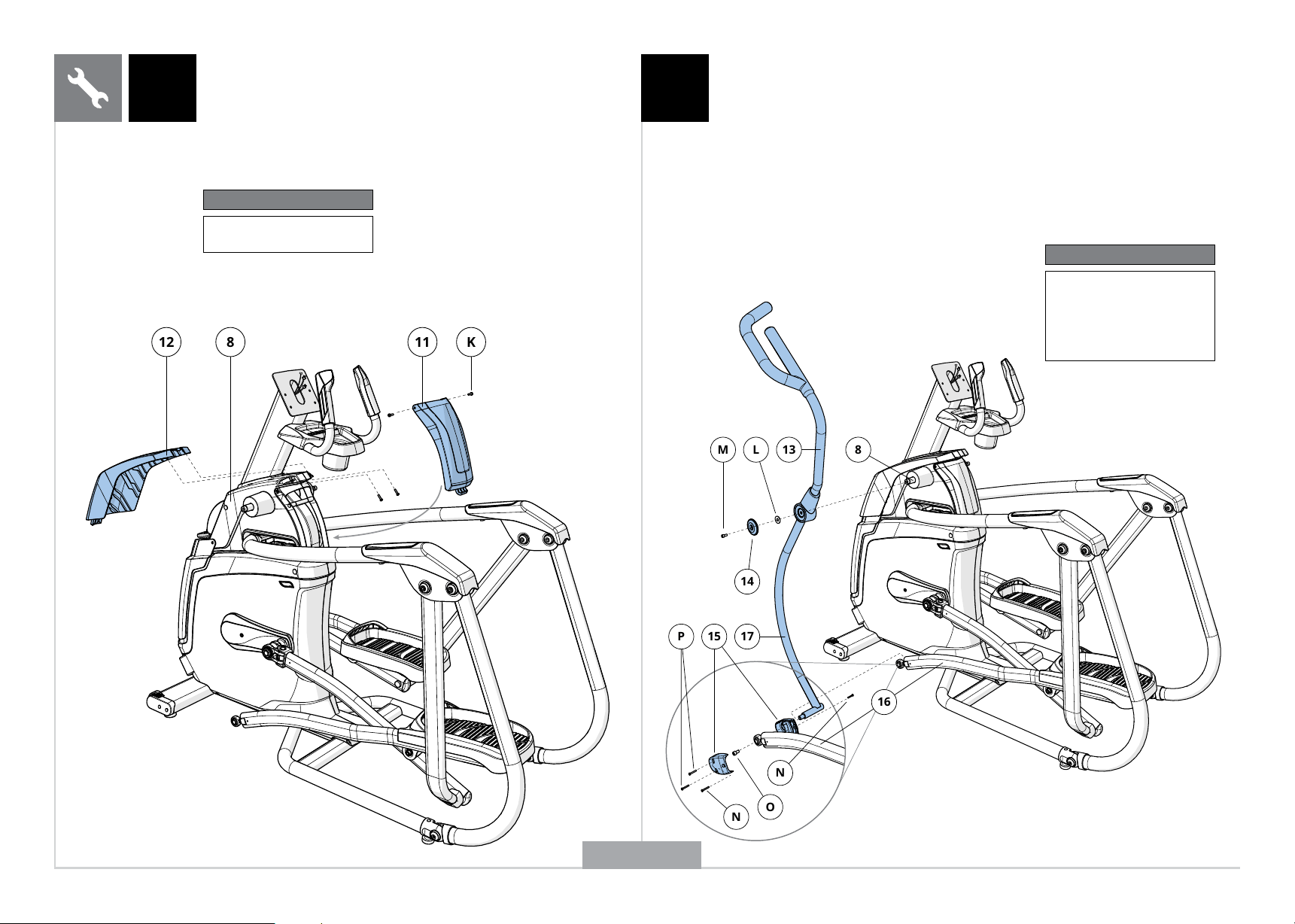
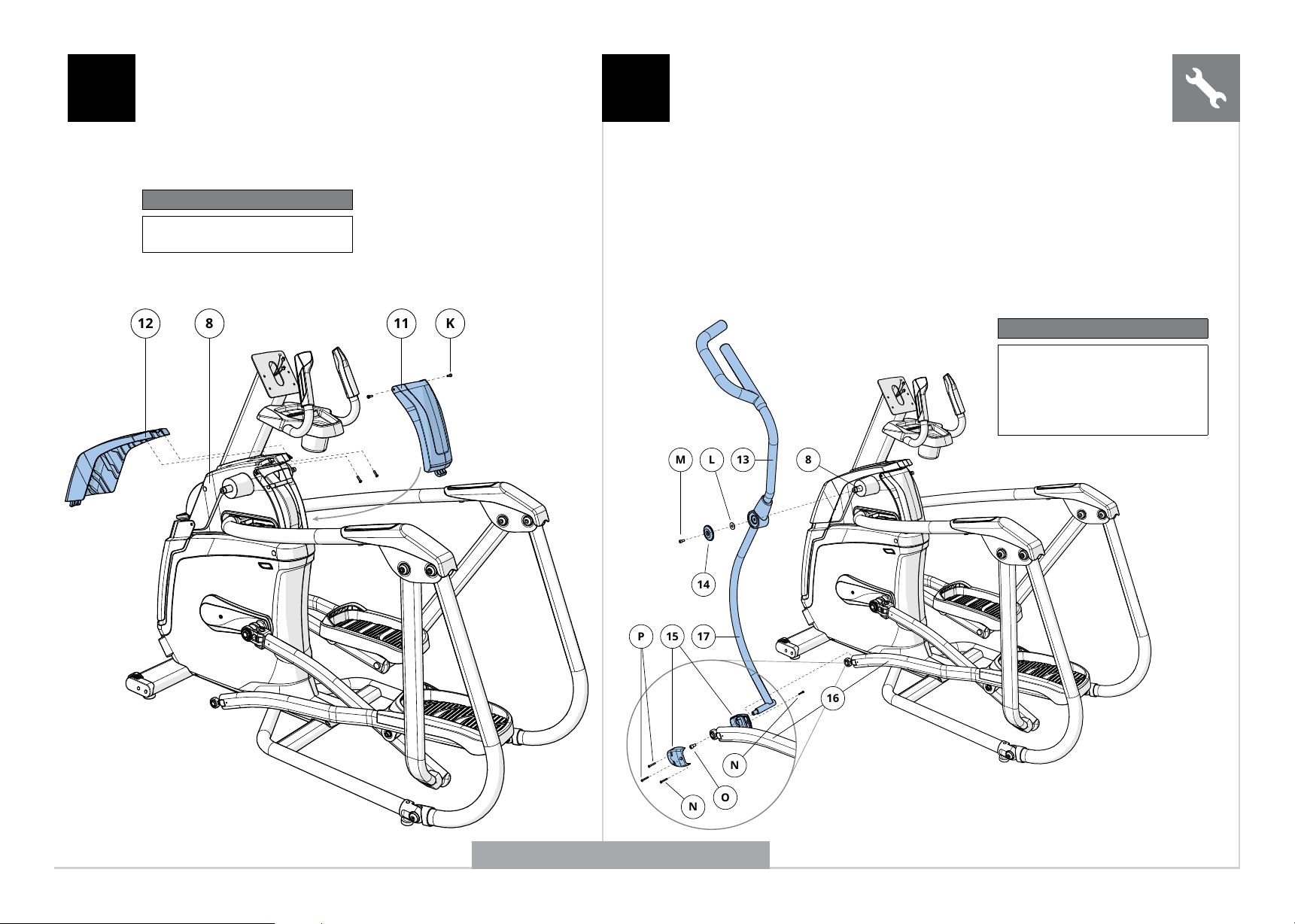
A Open HARDWARE FOR STEP 4.
B Attach the REAR TOP CAP COVER (11) to the
UPPER ASSEMBLY (8) using 2 SCREWS (L).
C Attach the FRONT TOP CAP COVER (12) to the
UPPER ASSEMBLY (8) using 2 SCREWS (K).
4 5
Hardware For Step 4
Description Qty
K Screw 4
Hardware For Step 5
Description Qty
L
M
N
O
P
Flat Washer
Bolt (20 mm)
Screw (8 mm)
Bolt (25 mm)
Screw (12 mm)
2
2
4
2
4
A Open HARDWARE FOR STEP 5.
B Slide the UPPER DUAL ACTION ARM (13) onto the UPPER ASSEMBLY
(9) and attach using 1 FLAT WASHER (L) , 1 HANDLEBAR CAP
(14) and 1 BOLT (M). Torque settings: 64.5 Nm / 47.6 lb-ft.
C Attach inside LINK ARM COVER (15) to LINK ARM (16) using 1 SCREW (N).
D Slide LINK ARM (16) onto the lower DUAL ACTION ARM (17) and
attach using 1 BOLT (O) and tighten to 80 Nm / 59 lb-ft.
E Attach outside LINK ARM COVER (15) to LINK ARM
(17) using 2 SCREWS (P) and 1 SCREW (N).
F Repeat steps B–E on other side.
G Move frame off Styrofoam base and cardboard.
A50 SHOWN
ENGLISH
9
18
Q
18
Q
20
7
21
R
5
6 7
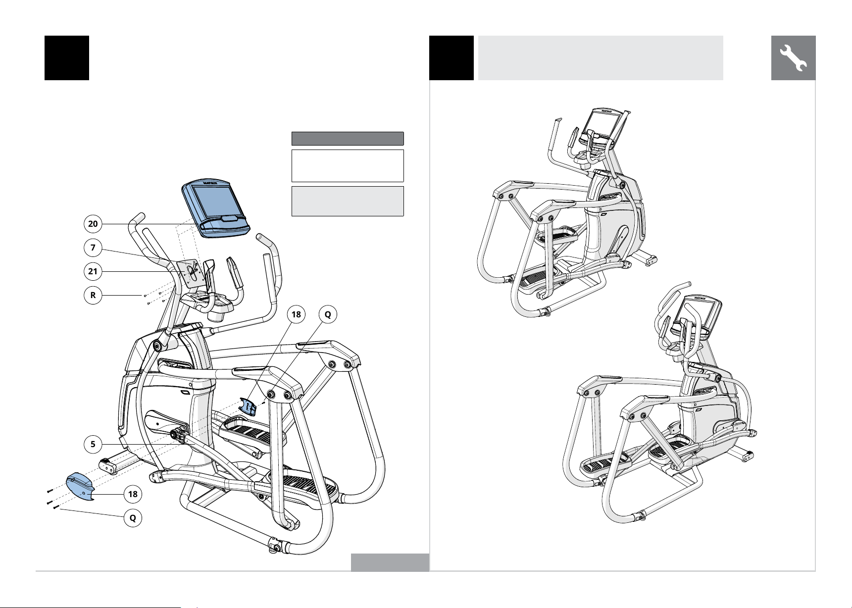
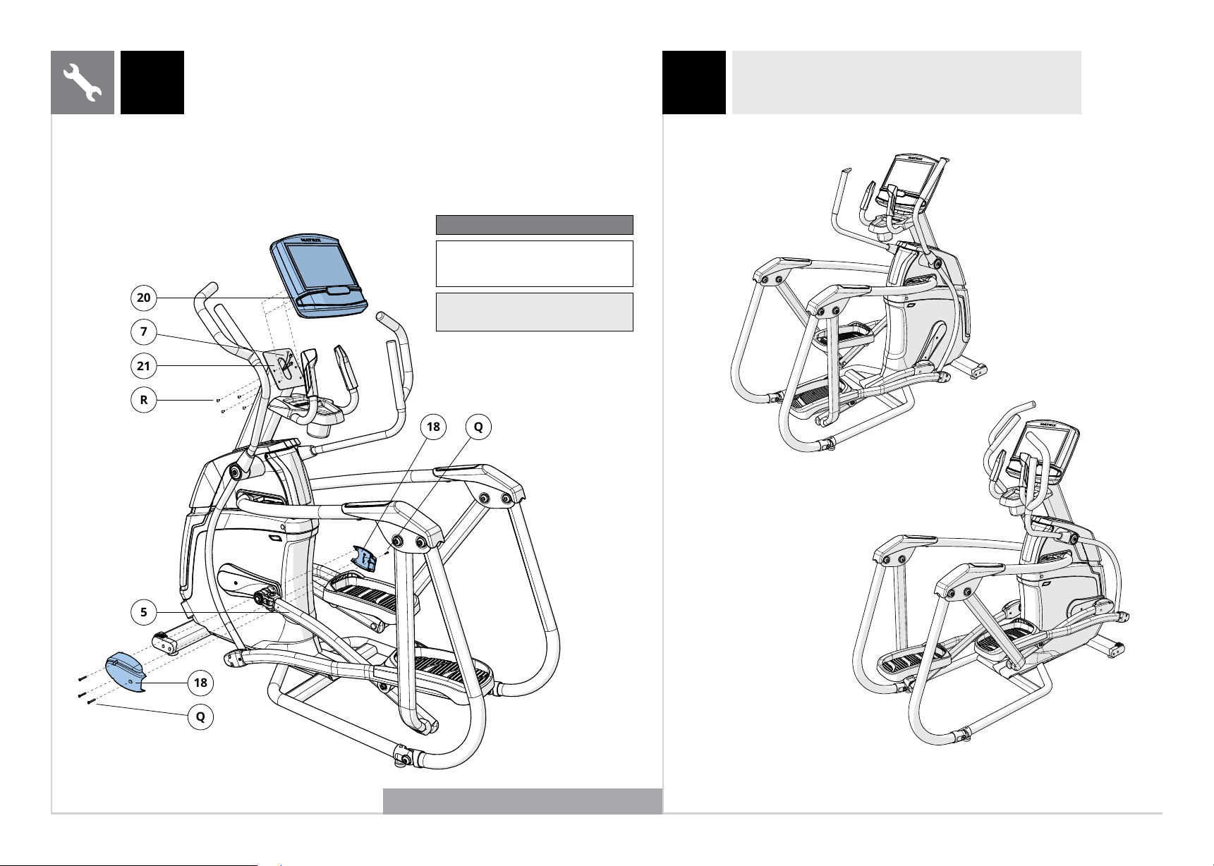
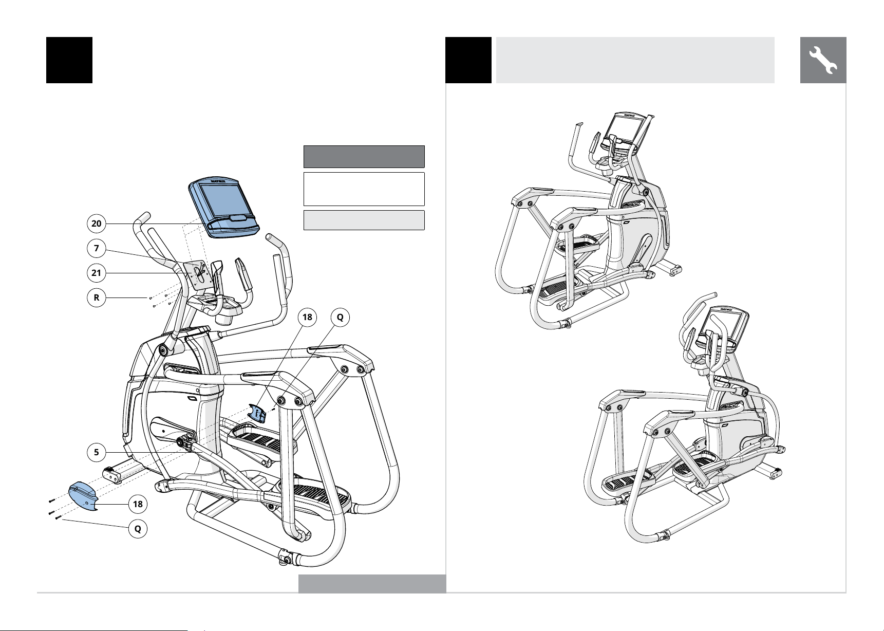
A Open HARDWARE FOR STEP 6.
B Attach the PEDAL ARM COVERS (18) to the LEFT
PEDAL ARM (5) using 4 SCREWS (Q).
C Connect the CABLES (8) to the CONSOLE (20) and carefully
tuck the excess cable into the CONSOLE MAST (21).
D Attach the CONSOLE (20) to the CONSOLE MAST (8) using 4 BOLTS (R).
A50 SHOWN
A30 / A50 ASSEMBLY COMPLETE!
Hardware For Step 6
Description Qty
Q
R
Screw
Bolt
4
4
Note: Be careful not to pinch
any wires while attaching the
console.
ENGLISH

10
AVERTISSEMENT !
Le processus de montage comporte certaines étapes au cours desquelles
il faut faire particulièrement attention. Il est indispensable de respecter
scrupuleusement les instructions de montage et de s’assurer que toutes les
pièces sont bien serrées. En cas de non-respect des instructions, certaines
parties de l’équipement pourraient être mal serrées, bouger et causer
des bruits gênants. Pour éviter d’endommager l’équipement, relisez les
instructions de montage et prenez les mesures correctives qui s’imposent.
PIÈCES INCLUSES :
F 1 cadre Ascent Trainer
F 1 support de barre supérieure
F 2 protections pour barre de maintien
F 1 ensemble de protection pour bras de pédale
F 1 ensemble supérieur
F 2 carters pour cadre d’inclinaison
F 1 embout de protection avant
F 1 embout de protection arrière
F 2 bras à action double inférieur/supérieur
F 2 ensembles de protection pour bras de liaison
F 2 embouts pour poignée
F 1 câble d’alimentation
F 1 kit de pièces de fixation
La console est vendue séparément
MONTAGE
Avant de commencer, cherchez le numéro de série qui se trouve sur une
étiquette où gure un code à barres et apposée sur votre Ascent trainer, puis
notez-le dans les cases ci-dessous.
NUMÉRO DE SÉRIE
NOM DU MODÈLE
F A30 F A50 ASCENT TRAINER MATRIX
* Utilisez les informations ci-dessus lorsque vous appelez l’assistance.
EMPLACEMENT DU NUMÉRO DE SÉRIE
DÉBALLAGE
Déballez l’équipement à l’endroit où
vous allez l’installer. Installez le carton
d’emballage sur une surface plane.
Il est conseillé de laisser le cadre
sur la base en polystyrène, jusqu’à
ce que vous soyez invité à le retirer.
N’ouvrez jamais le carton d’emballage
lorsqu’il est couché sur le côté.
BESOIN D’AIDE ?
Pour toute question ou si une pièce est manquante, contactez l’assistance technique.
Les coordonnées de l’assistance sont situées sur la carte d’information.
REMARQUES IMPORTANTES
À chaque étape du montage, assurez-vous
que TOUS les écrous et boulons sont bien
mis en place et partiellement serrés.
Certaines pièces ont été prélubriées an de faciliter leur
montage et fonctionnement. N’essuyez pas ces pièces
pour essayer d’ôter le lubriant. En cas de diculté,
appliquez une ne couche de graisse au lithium.
OUTILS INCLUS :
F Clé Allen de 6 mm
F Clé Allen de 8 mm
F Clé Allen de 10 mm
F Clé plate de 13/17 mm
F Tournevis cruciforme
FRANÇAIS
11
CONSOLE
SUPPORT DE LA CONSOLE
EMBOUT
POIGNÉE INFÉRIEURE
PÉDALIER
PRISE DE COURANT
BRAS DE LA PÉDALE
COMMUTATEURS DE
RÉSISTANCE/D’INCLINAISON
POIGNÉE SUPÉRIEURE
POIGNÉES AVEC CAPTEURS
TACTILES INTÉGRÉS
PORTE-BOUTEILLE
BARRE DE MAINTIEN SUPÉRIEURE
BRAS PIVOTANT
REPOSE-PIEDS
BRAS DE LIAISON
A30
FRANÇAIS
12
POIGNÉE SUPÉRIEURE
COMMUTATEURS DE
RÉSISTANCE/D’INCLINAISON
POIGNÉES AVEC CAPTEURS
TACTILES INTÉGRÉS
PORTE-BOUTEILLE
BARRE DE MAINTIEN SUPÉRIEURE
BRAS PIVOTANT
REPOSE-PIEDS
BRAS DE LIAISON
CONSOLE
SUPPORT DE LA CONSOLE
EMBOUT
POIGNÉE INFÉRIEURE
PÉDALIER
PRISE DE COURANT
BRAS DE LA PÉDALE
A50
FRANÇAIS
13
A Ouvrez le KIT COMPRENANT LES PIÈCES DE FIXATION POUR LA PREMIÈRE ÉTAPE.
B Soulevez délicatement la BARRE DE MAINTIEN SUPÉRIEURE (1) et alignez-la sur le CADRE PRINCIPAL (2).
C Retirez l’attache pour câble du CADRE PRINCIPAL (2).
D Fixez la BARRE DE MAINTIEN SUPÉRIEURE (1) au CADRE PRINCIPAL (2) en utilisant 1 BOULON (A),
2 RONDELLES PLATES (B) et 1 ÉCROU (C), puis serrez à un couple de 45,9 Nm/33,9 lb-ft.
E Attachez le SUPPORT DE BARRE SUPÉRIEURE (3) à la BARRE DE MAINTIEN SUPÉRIEURE (1) en utilisant 2 VIS (D).
F Fixez les PROTECTIONS POUR BARRE DE MAINTIEN (4) en utilisant 6 VIS (D) et 4 RONDELLES PLATES (E).
1
2
1
C
4
B
3
D
A
B
E
D
REPRÉSENTATION D’UN MODÈLE A50
Kit de pièces de xation pour l’étape 1
Description Qté
A
B
C
D
E
Boulon
Rondelle plate
Écrou
Vis
Rondelle plate
1
2
1
8
4
FRANÇAIS
14
2
A Ouvrez le KIT COMPRENANT LES PIÈCES DE
FIXATION POUR LA DEUXIÈME ÉTAPE.
B Faites glisser le BRAS DE LA PÉDALE GAUCHE (5) sur
le PÉDALIER (6) et fixez-le en utilisant 1 BOULON (F) et
1 ÉCROU (G), puis serrez à un couple de 77,4 Nm/57 lb-ft.
6
F
G
5
3
Kit de pièces de xation pour l’étape 2
Description Qté
F
G
Boulon
Écrou
1
1
9
8
H
I
10
2
J
7
A Ouvrez le KIT COMPRENANT LES PIÈCES DE
FIXATION POUR LA TROISIÈME ÉTAPE.
B Sortez délicatement le CÂBLE (7) à travers l’ENSEMBLE
SUPÉRIEUR (8) à l’aide du CÂBLE CONDUCTEUR (9)
situé à l’intérieur de l’ENSEMBLE SUPÉRIEUR (8).
C Fixez l’ENSEMBLE SUPÉRIEUR (8) au CADRE PRINCIPAL (2)
en utilisant 4 BOULONS (H) et 4 RONDELLES PLATES (I),
puis serrez à un couple de 64,5 Nm/47,6 lb-ft.
D Insérez 2 VIS (J) dans la partie inférieure
à l’arrière du CADRE PRINCIPAL (2).
E Insérez les CARTERS POUR CADRE D’INCLINAISON (10) dans
la partie inférieure de l’ENSEMBLE SUPÉRIEUR (8).
Kit de pièces de xation pour l’étape 3
Description Qté
H
I
J
Boulon
Rondelle plate
Vis
4
4
2
Remarque : Prenez garde de ne pincer
aucun câble lors de l’installation de
l’ensemble supérieur.
REPRÉSENTATION D’UN MODÈLE A50
FRANÇAIS
15
15
P
17
O
N
N
16
13
8
L
M
14
8
12
11
K
A Ouvrez le KIT COMPRENANT LES PIÈCES DE
FIXATION POUR LA QUATRIÈME ÉTAPE.
B Attachez l’EMBOUT DE PROTECTION ARRIÈRE (11)
à l’ENSEMBLE SUPÉRIEUR (8) en utilisant 2 VIS (L).
C Attachez l’EMBOUT DE PROTECTION AVANT (12)
à l’ENSEMBLE SUPÉRIEUR (8) en utilisant 2 VIS (K).
4 5
Kit de pièces de xation pour l’étape 4
Description Qté
K Vis 4
Kit de pièces de xation pour l’étape 5
Description Qté
L
M
N
O
P
Rondelle plate
Boulon (20 mm)
Vis (8 mm)
Boulon (25 mm)
Vis (12 mm)
2
2
4
2
4
A Ouvrez le KIT COMPRENANT LES PIÈCES DE
FIXATION POUR LA CINQUIÈME ÉTAPE.
B Faites glisser le BRAS À ACTION DOUBLE SUPÉRIEUR (13) sur l’ENSEMBLE
SUPÉRIEUR (9) et fixez-le en utilisant 1 RONDELLE PLATE (L), 1 EMBOUT POUR
POIGNÉE (14) et 1 BOULON (M). Réglage de couple : 64,5 Nm/47,6 lb-ft.
C Fixez la PROTECTION POUR LE BRAS DE LIAISON INTÉRIEURE (15)
au BRAS DE LIAISON (16) en utilisant 1 VIS (N).
D Faites glisser le BRAS DE LIAISON (16) sur le BRAS À
ACTION DOUBLE INFÉRIEUR (17) et attachez-le en utilisant
1 BOULON (O), puis serrez à un couple de 80 Nm/59 lb-ft.
E Fixez la PROTECTION POUR LE BRAS DE LIAISON EXTÉRIEURE (15)
au BRAS DE LIAISON (17) en utilisant 2 VIS (P) et 1 VIS (N).
F Répétez les étapes B à E pour l’autre côté de l’appareil.
G Retirez le cadre de la base en polystyrène et du carton.
REPRÉSENTATION D’UN MODÈLE A50
FRANÇAIS
16
18
Q
18
Q
20
7
21
R
5
6 7
A Ouvrez le KIT COMPRENANT LES PIÈCES DE
FIXATION POUR LA SIXIÈME ÉTAPE.
B Attachez les PROTECTIONS POUR BRAS DE PÉDALE (18) au
BRAS DE LA PÉDALE GAUCHE (5) en utilisant 4 VIS (Q).
C Branchez les CÂBLES (8) sur la CONSOLE (20) et rentrez avec
précaution l’excès de câble dans le SUPPORT DE LA CONSOLE (21).
D Fixez la CONSOLE (20) au SUPPORT DE LA
CONSOLE (8) en utilisant 4 BOULONS (R).
REPRÉSENTATION D’UN MODÈLE A50
A30/A50 – MONTAGE TERMINÉ !
Kit de pièces de xation pour l’étape 6
Description Qté
Q
R
Vis
Boulon
4
4
Remarque : prenez garde de ne pincer
aucun câble lors de l’installation de la
console.
FRANÇAIS
17
ADVERTENCIA
El proceso de montaje tiene varios pasos que requieren una atención
especial. Es muy importante seguir correctamente las instrucciones de
montaje y asegurarse de que todas las partes están rmemente ajustadas.
Si no se siguen correctamente las instrucciones de montaje, es posible
que haya piezas del equipo que no estén apretadas y provoquen ruidos
molestos. Para evitar daños en el equipo, debe consultar las instrucciones
de montaje y llevar a cabo las medidas correctivas que se precisen.
COMPONENTES INCLUIDOS:
F 1 bastidor de Ascent Trainer
F 1 soporte de los raíles superiores
F 2 cubiertas para los pasamanos
F 1 kit de cubierta para brazos de pedales
F 1 conjunto de estructura superior
F 2 patas de inclinación del bastidor
F 1 cubierta delantera de la tapa superior
F 1 cubierta trasera de la tapa superior
F 2 brazos superiores/inferiores de acción dual
F 2 kits de cubierta para brazos de conexión
F 2 tapas de asideros
F 1 cable de alimentación
F 1 bolsa de accesorios
La consola se vende por separado.
MONTAJE
Antes de comenzar, busque el número de serie de la Ascent Trainer, que se halla
ubicado en una etiqueta de código de barras y anótelo en el espacio que se
encuentra a continuación.
NÚMERO DE SERIE
NOMBRE DEL MODELO:
F A30 F A50 MÁQUINA DE ENTRENAMIENTO
MATRIX ASCENT TRAINER
* Indique la información que se menciona arriba cuando llame a la asistencia técnica.
UBICACIÓN DEL NÚMERO DE SERIE
DESEMBALAJE
Desembale el equipo donde lo vaya
a emplear. Coloque el paquete sobre
una supercie plana nivelada. Le
recomendamos que deje el bastidor
en la base de poliestireno extruído
hasta que las instrucciones le indiquen
que debe utilizarla. Nunca abra la
caja si esta está sobre un lateral.
¿NECESITA AYUDA?
Si tiene alguna duda o le falta algún componente, póngase en contacto con el servicio de asistencia
técnica al consumidor. Puede encontrar la información de contacto en la tarjeta de información.
NOTAS IMPORTANTES
Asegúrese de que TODOS los pernos y todas
las tuercas están en su sitio y parcialmente
apretados en todos los pasos del montaje.
Varios componentes se han lubricado previamente
para facilitar el montaje y la utilización. Por favor,
no limpie el lubricante. Si tiene dicultades, se
recomienda aplicar una ligera capa de grasa de litio.
HERRAMIENTAS INCLUIDAS:
F Llave Allen de 6 mm
F Llave Allen de 8 mm
F Llave Allen de 10 mm
F Llave plana de 13/17 mm
F Destornillador de estrella
ESPAÑOL
18
CONSOLA
MÁSTIL DE LA CONSOLA
TAPA SUPERIOR
ASIDERO INFERIOR
BIELAS
ENCHUFE DEL CABLE
DE ALIMENTACIÓN
BRAZO DEL PEDAL
CONMUTADORES DE RESISTENCIA/INCLINACIÓN
ASIDERO SUPERIOR
ASIDEROS CON PULSÓMETRO
PORTABOTELLA
PASAMANOS SUPERIOR
BRAZO OSCILANTE
REPOSAPIÉS
BRAZO DE CONEXIÓN
A30
ESPAÑOL
19
ASIDERO SUPERIOR
CONMUTADORES DE RESISTENCIA/INCLINACIÓN
ASIDEROS CON PULSÓMETRO
PORTABOTELLA
PASAMANOS SUPERIOR
BRAZO OSCILANTE
REPOSAPIÉS
BRAZO DE CONEXIÓN
CONSOLA
MÁSTIL DE LA CONSOLA
TAPA SUPERIOR
ASIDERO INFERIOR
BIELAS
ENCHUFE DEL CABLE
DE ALIMENTACIÓN
BRAZO DEL PEDAL
A50
ESPAÑOL
20
1
2
1
C
4
B
3
D
A
B
E
D
FIGURA DEL MODELO A50
Componentes necesarios para
el paso 1
Descripción Cantidad
A
B
C
D
E
Perno
Arandela plana
Tuerca
Tornillo
Arandela plana
1
2
1
8
4
A Abra los COMPONENTES NECESARIOS PARA EL PASO 1.
B Levante con suavidad el PASAMANOS SUPERIOR (1) y alinéelo con el BASTIDOR PRINCIPAL (2).
C Retire la brida del BASTIDOR PRINCIPAL (2).
D Acople el PASAMANOS SUPERIOR (1) al BASTIDOR PRINCIPAL (2) utilizando 1 PERNO (A), 2 ARANDELAS PLANAS (B)
y 1 TUERCA (C) y apriete hasta 45,9 Nm / 33,9 lb-ft.
E Una el SOPORTE DE LOS RAÍLES SUPERIORES (3) al PASAMANOS SUPERIOR (1) utilizando 2 TORNILLOS (D).
F Monte las CUBIERTAS DE LOS PASAMANOS (4) utilizando 6 TORNILLOS (D) y 4 ARANDELAS PLANAS (E).
ESPAÑOL
21
A Abra los COMPONENTES NECESARIOS PARA EL PASO 2.
B Deslice el BRAZO DEL PEDAL IZQUIERDO (5) para encajarlo en la
BIELA (6) y acóplelo utilizando 1 PERNO (F) y 1 TUERCA (G); apriete
hasta 77,4 Nm / 57 lb-ft.
6
F
G
5
2 3
Componentes necesarios para
el paso 2
Descripción Cantidad
F
G
Perno
Tuerca
1
1
9
8
H
I
10
2
J
7
A Abra los COMPONENTES NECESARIOS PARA EL PASO 3.
B Tire con cuidado del CABLE (7) pasándolo a través del CONJUNTO
DE ESTRUCTURA SUPERIOR (8) y sirviéndose del CABLE GUÍA (9)
situado dentro del CONJUNTO DE ESTRUCTURA SUPERIOR (8).
C Instale el CONJUNTO DE ESTRUCTURA SUPERIOR (8)
al BASTIDOR PRINCIPAL (2) utilizando 4 PERNOS (H)
y 4 ARANDELAS PLANAS (I) y apriete hasta 64,5 Nm / 47,6 lb-ft.
D Inserte 2 TORNILLOS (J) en la parte inferior trasera del
BASTIDOR PRINCIPAL (2).
E Inserte las PATAS DE INCLINACIÓN DEL BASTIDOR (10) en la
zona inferior del CONJUNTO DE ESTRUCTURA SUPERIOR (8).
Componentes necesarios para
el paso 3
Descripción Cantidad
H
I
J
Perno
Arandela plana
Tornillo
4
4
2
Nota: Tenga cuidado de no
pillar ningún cable al instalar el
conjunto de estructura superior.
FIGURA DEL MODELO A50
ESPAÑOL

22
15
P
17
O
N
N
16
13
8
L
M
14
8
12
11
K
A Abra los COMPONENTES NECESARIOS PARA EL PASO 4.
B Monte la CUBIERTA DE LA TAPA SUPERIOR TRASERA (11) en
el CONJUNTO DE ESTRUCTURA SUPERIOR (8) utilizando 2
TORNILLOS (L).
C Monte la CUBIERTA DE LA TAPA SUPERIOR DELANTERA (12)
en el CONJUNTO DE ESTRUCTURA SUPERIOR (8) utilizando
2 TORNILLOS (K).
4 5
Componentes necesarios para
el paso 4
Descripción Cantidad
K Tornillo 4
Componentes necesarios para
el paso 5
Descripción Cantidad
L
M
N
O
P
Arandela plana
Perno (20 mm)
Tornillo (8 mm)
Perno (25 mm)
Tornillo (12 mm)
2
2
4
2
4
A Abra los COMPONENTES NECESARIOS PARA EL PASO 5.
B Deslice el BRAZO DE ACCIÓN DUAL SUPERIOR (13) encajándolo en el CONJUNTO
DE ESTRUCTURA SUPERIOR (9) y acóplelo utilizando 1 ARANDELA PLANA (L) ,
1 TAPA DE ASIDERO (14) y 1 PERNO (M). Ajustes del par de apriete: 64,5 Nm /
47,6 lb-ft.
C Monte la CUBIERTA INTERIOR DEL BRAZO DE CONEXIÓN (15) al BRAZO DE
CONEXIÓN (16) utilizando 1 TORNILLO (N).
D Deslice el BRAZO DE CONEXIÓN (16) encajándolo con el BRAZO DE ACCIÓN DUAL
INFERIOR (17) y acóplelo utilizando 1 PERNO (O); apriete hasta 80 Nm / 59 lb-ft.
E Monte la CUBIERTA EXTERIOR DEL BRAZO DE CONEXIÓN (15) en el BRAZO DE
CONEXIÓN (17) utilizando 2 TORNILLOS (P) y 1 TORNILLO (N).
F Repita los pasos B-E en el otro lado.
G Saque el bastidor de su embalaje de cartón y poliestireno extruído.
FIGURA DEL MODELO A50
ESPAÑOL
23
18
Q
18
Q
20
7
21
R
5
6 7
A Abra los COMPONENTES NECESARIOS PARA EL PASO 6.
B Monte las CUBIERTAS DE LOS BRAZOS DE LOS PEDALES (18) al
BRAZO DEL PEDAL IZQUIERDO (5) utilizando 4 TORNNILLOS (Q).
C Conecte los CABLES (8) a la CONSOLA (20) e introduzca presionando
suavemente el exceso de cable dentro del MÁSTIL DE LA CONSOLA (21).
D Instale la CONSOLA (20) acoplándola al MÁSTIL DE LA CONSOLA (8)
con 4 PERNOS (R).
FIGURA DEL MODELO A50
¡HA COMPLETADO EL MONTAJE DEL A30 / A50!
Componentes necesarios para
el paso 6
Descripción Cantidad
Q
R
Tornillo
Perno
4
4
Nota: Tenga cuidado de no pillar
ningún cable al instalar la consola.
ESPAÑOL

© 2016 Johnson Health Tech
Rev 1.1 A
A30
A50