담 당 관리자
MODEL
BRAND
Printing Specification
1. Trim Size (Format) : 185 mm x 260 mm
2. Printing Colors : 1 Color (BLACK)
3. Stock (Paper) : Uncoated paper, WHITE PAPER 80 g/㎡
4. Printing Method :
5. Bindery : Saddle stitch
6. Language : EN
7. Number of pages : 40 pages
•This part contain Eco-hazardous substances (Pb, Cd, Hg, Cr6+, PBB, PBDE, etc.) within LG
standard level, Details should be followed Eco-SCM management standard[LG(56)-A-2524].
Especially, Part should be followed and controlled the following specification.
(1)Eco-hazardous substances test report should be submitted when Part certification test
and First Mass Production.
(2) Especially, Don’t use or contain lead(Pb) and cadmium(Cd) in ink.
Model Description
Part No.
2.
User’s Guide Specification
1.
User’s Guide Specification
Changes
4.
REV.
NO.
MM/DD/YY
SIGNATURE
CHANGE NO.
CHANGE CONTENTS
1
4
5
6
8
7
SUFFIX
CHOI MJ
06.08.17
RF052A
LG
38289U0515A
KANG KS
06.08.17
(1) Origin Notification
* LGEDI : Printed in Indonesia * LGEWA : Printed in U.K. * LGEMA : Printed in Poland
* LGESP : Printed in Brazil * LGEMX : Printed in Mexico
* LGENT : Printed in China * LGEIL : Printed in India
* Other Oversea Factories : NON
9
10
Special Instructions3.
Product Name
OWNER’S MANUAL
WITH AV
2
3
08/17/06 CHOI MJ S6-53145
Amend Printing Specification

Pagination sheet
Pagination sheet
Front
Cover
(EN)
P/NO. 38289U0515A
Total pages : 40 pages
P/NO.
23…
Back
Cover
(EN)
11 39…21…
Please read this manual carefully before operating your set.
Retain it for future reference.
Record model number and serial number of the set.
See the label attached on the back cover and quote this infor-
mation to your dealer when you require service.
Model number :
Serial number :
PLASMA MONITOR
OWNER’S MANUAL
P/NO : 38289U0515A (RF052A, 017M/N TX) a
2 PLASMA MONITOR
Safety Warnings
Safety Instructions
Safety Instructions
Do not place the set in direct sunlight or near heat
sources such as heat registers, stove and so on.
- This may cause a fire.
Do not use the set in damp place such as a bathroom
or any place where it is likely to get wet.
- This may cause a fire or could give an electric shock.
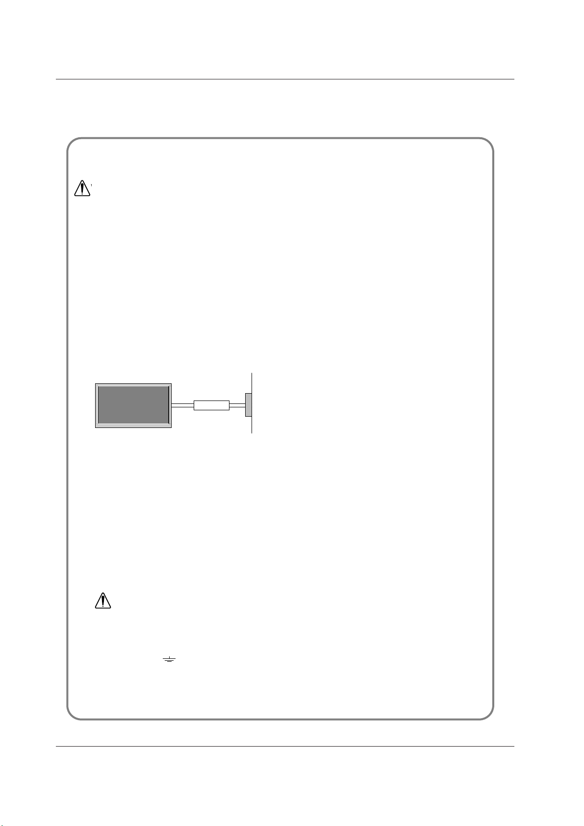
Bend antenna cable between inside and outside
building to prevent rain from flowing in.
- This may cause water damaged inside the set and could give an
electric shock.
Earth wire should be connected.
- If the earth wire is not connected, there is possible a danger of
electric shock caused by the current leakage.
- If grounding methods are not possible, a separate circuit break-
er should be employed and installed by a qualified electrician.
- Do not connect ground to telephone wires, lightning rods or gas
pipe.
Apparatus shall not be exposed to dripping or splash-
ing and no objects filled with liquids, such as vases,
shall be placed on the apparatus.
Do not insert any object into the exhaust vent.
- This may cause a fire or could give an electric shock.
Do not place heavy objects on the set.
- This may cause serious injury to a child or adult.
Do not use water while cleaning the set.
- This may cause damaged the set or could give an electric
shock.
In case of smoke or strange smell from the set, switch
it off ,unplug it from the wall outlet and contact your
dealer or service center.
- This may cause a fire or could give an electric shock.
Do not attempt to service the set yourself. Contact
your dealer or service center.
- This may cause damaged the set or could give an electric
shock.
During a lightning thunder, unplug the set from the
wall outlet and don’t touch an antenna cable.
- This may cause damaged the set or could give an electric
shock.
DISCONNECTING DEVICE FROM MAINS
- Mains plug is the disconnecting device. The plug must remain
readily operable.
Use a dedicated power cord. Do not modify or extend
the power cord.
Do not install, remove, or reinstall the unit by yourself
(customer).
For electrical work, contact the dealer, seller, a
qualified electrician, or an Authorized Service
Center. For installation, always contact the dealer or
an Authorized Service Center.
Do not use if the power cord or plug is damaged, or
socket is loose. Use a dedicated outlet for this
appliance.
Do not over bend the power cord and do not place
anything on the power cord. Do not install the
monitor near any sharp edge to avoid wire damage.
W
WARNING
Short-circuit
breaker
Power
supplier
• It is recommended that 42/50PM1MH / 60PZ9MH / 42PM3MVH model only be used at an altitude of less than
6561 feet (2000m) to get the best quality picture and sound.
WARNING
in U.K. only
*
This set is supplied with a BS 1363 approved 13 amp mains plug, fused at 13 amp. When replacing the fuse
always use a 13 amp BS 1362, BSI or ASTA approved type. Never use this plug with the fuse cover omitted. To
obtain a replacement fuse cover contact your dealer or “LG Electronics U.K. Ltd.” If the type of plug supplied is not
suitable for the mains sockets in your home, then the plug should be removed and a suitable type fitted.
A mains plug removed from the mains lead of this set must be destroyed. A mains plug with bared wires is
hazardous if inserted in a mains socket. Do not connect either wire to the earth pin, marked with the letter E or
with the earth symbol or coloured green or green and yellow. If any other plug is fitted, use a 13 amp fuse,
either in the plug, or at the distribution board.
The wires in this mains lead are coloured in accordance with the following codes:
As the colours of the wires in the mains lead of this set may not correspond with the coloured marking identify-
ing the terminals in your plug, proceed as follows: The wire which is coloured blue must be connected to the ter-
minal which is marked with the letter N or coloured black. The wire which is coloured brown must be connected
to the terminal which is marked with the letter L or coloured red.
BLUE: NEUTRAL, BROWN: LIVE
Owner’s Manual 3
Safety Warnings
Never touch the power plug with a wet hand.
- This may cause an electric shock.
Disconnect from the mains and remove all connec-
tions before moving.
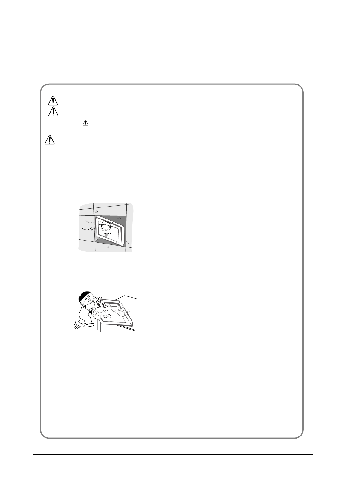
Do not place the set in a built-in installation such as a
bookcase or rack.
- Ventilation required.
When installing the set on a table, be careful not to
place the edge of its stand.
- This may cause the set to fall, causing serious injury to a child or
adult, and serious damage to the set.
Do not place an outside antenna in the vicinity of over-
head power lines or other electric light or power cir-
cuits.
- This may cause an electric shock.
There should be enough distance between an outside
antenna and power lines to keep the former from
touching the latter even when the antenna falls.
- This may cause an electric shock.
Do not pull the cord but the plug when unplugging.
- This may cause a fire.
Ensure the power cord doesn’t trail across any hot
objects like a heater.
- This may cause a fire or an electric shock.
Do not plug when the power cord or the plug is dam-
aged or the connecting part of the power outlet is
loose.
- This may cause a fire or an electric shock.
Dispose of used batteries carefully to protect a child
from eating them.
- In case that it eats them, take it to see a doctor immediately.
When moving the set assembled with speakers do not
carry holding the speakers.
- This may cause the set to fall, causing serious injury to a child or
adult, and serious damage to the set.
Unplug this product from the wall outlet before clean-
ing. Do not use liquid cleaners or aerosol cleaners.
- This may cause damaged the set or could give an electric shock.
Contact the service center once a year to clean the
internal part of the set.
- Accumulated dust can cause mechanical failure.
The distance between eyes and the screen should be
about 5 ~ 7 times as long as diagonal length of the
screen.
- If not, eyes will strain.
Unplug the set from the wall outlet when it is left
unattended and unused for long periods of time or
occurred a state of emergency.
- Accumulated dust may cause a fire or an electric shock from
deterioration or electric leakage.
NOTES
*
Safety instructions have two kinds of information, and each meaning of it is as below.
Take care of danger that may happen under specific condition.
The violation of this instruction may cause serious injuries and even death.
The violation of this instruction may cause light injuries or damage of the
product.
WARNING
NOTES
4 PLASMA MONITOR
Contents
After reading this manual,
keep it in the place where
the user can always
contact easily.
Safety Warnings
Safety Instructions . . . . . . . . . . . . . . . . . . . . . . .2~3
Introduction
Remote Control Key Functions . . . . . . . . . . . . . . . .6
Location and Function of Controls . . . . . . . . . .7~10
Installation
External Equipment Viewing Setups . . . . . . . .11~12
Displayable Monitor Specification . . . . . . . . . . . . .13
HDMI . . . . . . . . . . . . . . . . . . . . . . . . . . . . . . .14~15
Accessories . . . . . . . . . . . . . . . . . . . . . . . . . . . . .16
Installation Options . . . . . . . . . . . . . . . . . . . . . . .17
Operation
Turning on the Set . . . . . . . . . . . . . . . . . . . . . . . .18
On-Screen Menu Language Selection (option) . . .18
Picture Menu Options
PSM (Picture Status Memory) . . . . . . . . . . . . . . .19
CSM (Color Status Memory) . . . . . . . . . . . . . . . .19
Manual Colour Temperature Control . . . . . . . . . . .19
. . . . . . . . . . . . . . . . . . . . . . . . . . . . . . . . . .19
sRGB (RGB[PC], HDMI[PC] mode only) . . . . . . . .20
ACM (Active Color Management) . . . . . . . . . . . . .20
Manual Picture Control . . . . . . . . . . . . . . . . . . . . .20
Sound Menu Options
SSM (Sound Status Memory) . . . . . . . . . . . . . . . .21
BBE . . . . . . . . . . . . . . . . . . . . . . . . . . . . . . . . . . .21
AVL (Auto Volume Leveler) . . . . . . . . . . . . . . . . .21
Adjusting Sound Control . . . . . . . . . . . . . . . . . . .22
Speaker . . . . . . . . . . . . . . . . . . . . . . . . . . . . . . . .22
Time Menu Options
Setting the Clock . . . . . . . . . . . . . . . . . . . . . . . . .23
Setting the On/Off Timer . . . . . . . . . . . . . . . . . . .23
Auto Sleep . . . . . . . . . . . . . . . . . . . . . . . . . . . . . .23
Sleep Timer . . . . . . . . . . . . . . . . . . . . . . . . . . . . .23
Special Menu Options
Child Lock . . . . . . . . . . . . . . . . . . . . . . . . . . . . . .24
ISM (Image Sticking Minimization) Method . . . . . .24
Low Power . . . . . . . . . . . . . . . . . . . . . . . . . . . . . .25
Demo . . . . . . . . . . . . . . . . . . . . . . . . . . . . .25
Menu Rotation for Vertical Viewing (option) . . . . .25
Screen Menu Options
Auto adjustment . . . . . . . . . . . . . . . . . . . . . . . . . .26
Manual Configure . . . . . . . . . . . . . . . . . . . . . . . .26
Selecting Wide VGA/XGA mode . . . . . . . . . . . . . .26
Initializing (Reset to original factory value) . . . . . .26
Setting Picture Format . . . . . . . . . . . . . . . . . . . . .27
Picture Size Zoom . . . . . . . . . . . . . . . . . . . . . . . .27
Screen Position . . . . . . . . . . . . . . . . . . . . . . . . . .27
Cinema . . . . . . . . . . . . . . . . . . . . . . . . . . . . . . . .28
NR (Noise Reduction) . . . . . . . . . . . . . . . . . . . . .28
Split Zoom . . . . . . . . . . . . . . . . . . . . . . . . . . . . . .28
Miscellaneous
External Control Device Setup . . . . . . . . . . . .29~34
IR Code (NEC Format) . . . . . . . . . . . . . . . . . .35~37
Troubleshooting Checklist . . . . . . . . . . . . . . . . . .38
Product Specifications . . . . . . . . . . . . . . . . . . . . .39
Contents
Contents
Disposal of your old appliance
1. When this crossed-out wheeled bin symbol is attached to a product it
means the product is covered by the European Directive 2002/96/EC.
2. All electrical and electronic products should be disposed of separately
from the municipal waste stream via designated collection facilities
appointed by the government or the local authorities.
3. The correct disposal of your old appliance will help prevent potential
negative consequences for the environment and human health.
4. For more detailed information about disposal of your old appliance,
please contact your city office, waste disposal service or the shop
where you purchased the product.

Owner’s Manual 5
Introduction
Introduction
Introduction
What is a Plasma Display ?
If voltage is inputted to gas in glass panels, ultraviolet rays is outputted and fused with a fluorescent substance. At this moment,
light is emitted. A Plasma Display is a next generation flat Display using this phenomenon.
160° - Wide angle range of vision
A Plasma Display provides more than 160° angle range of vision so that you can get a picture without distortion from any
direction.
Easy installation
A Plasma Display is much lighter and smaller than other same class products so that you can install the Plasma Display
at the desired place.
Big screen
The screen of a Plasma Display is 42" (50" or 60") so that you can get vivid experience as if you are in a theater.
Multimedia Plasma Display
A Plasma Display can be connected with a computer so that you can use it as a screen for conference, game, internet
and so on.
The explanation about coloured dots may be present on PDP screen
The PDP which is the display device of this product is composed of 0.9 to 2.2 million cells and a few cell defects can occur
in the manufacture of the PDP. Several coloured dots visible on the screen would be acceptable, in line with other PDP
manufacturers and would not mean that the PDP is faulty. We hope you will understand that the product which corre-
sponds to this standard is regarded as acceptable. It means that it could not be changed or refunded.
We promise that we'll do our best to develop our technology to minimize the cell defects.
The explanation about noise of PDP (option)
In the same way that a fan is used in a PC to keep the CPU cool, the PDP is equipped with cooling fans to improve the
reliability of this product. Therefore, a certain level of noise could occur when the fan is operated. This noise doesn't have
any negative effect on its efficiency and liability and it's also determined to have no difficulty while using this product. The
noise from the fans is normal in the operation of this product. We hope you will understand that a certain level of noise is
acceptable. It means that it is not changeable nor refundable.
TO AVOID BURNING IMAGE INTO THE DISPLAY, DO NOT HAVE A STILL IMAGE ON SCREEN FOR
EXTENDED PERIOD OF TIME. IMAGE AFTER BURN WILL NOT BE COVERED UNDER WARRANTY
ie.Menus, Video games, Borders or LOGOS
WARNING
This is Class A product. In a domestic environment this product may cause radio interference in which
case the user may be required to take adequate measures.
WARNING
TO REDUCE THE RISK OF FIRE AND ELECTRIC SHOCK, DO NOT EXPOSE THIS PRODUCT TO
RAIN OR MOISTURE.
6 PLASMA MONITOR
Introduction
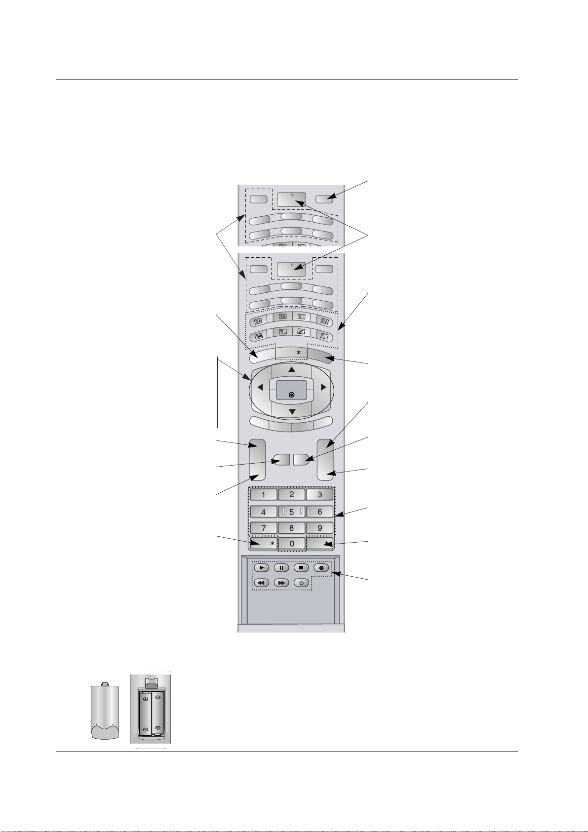
Remote Control Key Functions
Remote Control Key Functions
- When using the remote control aim it at the remote control sensor of the set.
- There maybe a defect in consecutive operation of remote control in a specified brightness according to this set.
• Open the battery compartment cover on the back side and insert
the batteries with correct polarity.
• Install two 1.5V alkaline batteries of AA type. Don’t mix used bat-
teries with new batteries.
Installing Batteries
INPUT
RGB
HDMI
INDEX
HOLD
POSITION
C
O
M
P
O
N
E
N
T1
AV
S
IZ
E
COMPONENT2
MULTIMEDIA
POWER
S-VIDEO
INPUT
RGB
HDMI
INDEX
MIX
HOLD
MODE
POSITION
REVEAL
S-VID
E
O
2
AV1
S
IZ
E
T
IM
E
AV3
MENU
TEXT/
SPLIT
ZOOM
ARC
OK
VOL VOL
PSM
SSM
SLEEP
I/II
COMPONENT
POWER
AV2
MUTE
M
?
LIST/
Q.VIEW/
MULTIMEDIA
Selects the Component, RGB or HDMI
modes.
POWER
switches the set on from standby or off to
standby.
NUMBER buttons
LIST (option)
displays the programme table.
VCR BUTTONS
Controls a video cassette recorder.
PSM
Adjusts the factory preset picture accord-
ing to the room.
ARC
changes the picture format.
SSM
To select the sound appropriate to your
viewing programme.
MUTE
Switches the sound on or off.
TEXT/
*
(option)
These buttons are used for teletext.
For further details, see the ‘Teletext’ sec-
tion.
COLOURED BUTTONS :
These buttons are used for teletext.
INPUT
MENU
displays on screen menus one by one.
exits the current menu.
memorizes menu changes.
SLEEP
Sets the sleep timer.
SPLIT ZOOM
enlarge the screen with regular ration.
I/II
(option)
Selects the language during dual language
broadcast.
Selects the sound output.
Q.VIEW (option)
Returns to the previously viewed
programme.
Note : This function works only when
Favourite prog. is set to Off. Otherwise
each press of this button will select a stored
favourite programme.
DD
/
EE
Selects a menu option.
FF
/
GG
(Volume Up/Down)
Increases/decreases sound level.
Adjusts menu settings.
OK
accepts your selection or displays the
current mode.
Owner’s Manual 7
Introduction
Location and Function of Controls
Location and Function of Controls
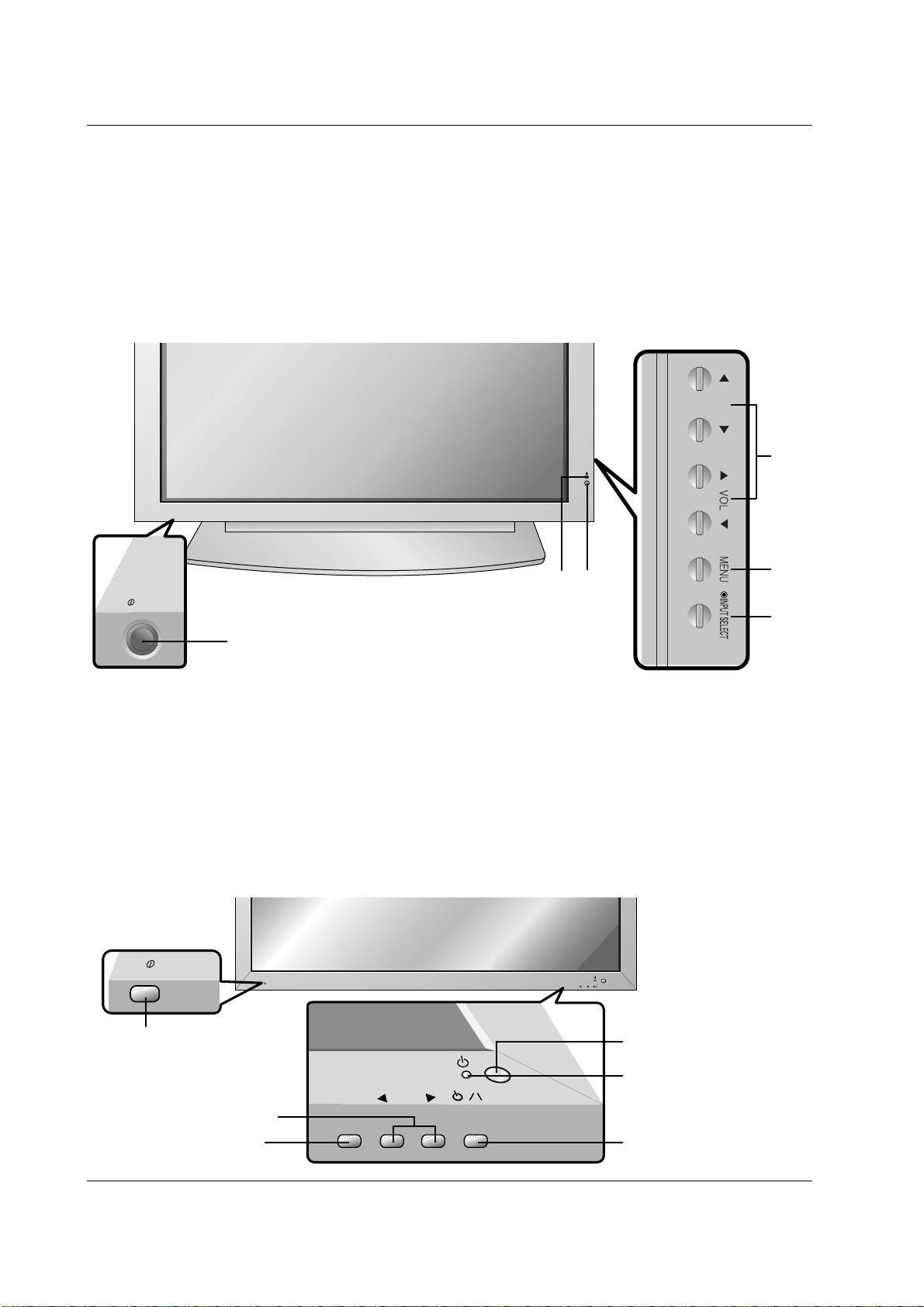
<Front Panel Controls>
60PZ9M/H series
42PM1M/H series / 50PM1M/H series
ON/OFF
- Shown is a simplified representation of the set.
- Here shown may be somewhat different from your set.
1. Main Power Button
2. Remote Control Sensor
3. Power Standby Indicator
Illuminates red in standby mode, Illuminates green when the
set is turned on
4. INPUT SELECT Button
5. MENU
Displays on screen menus one by one.
Exits the current menu.
Memorizes menu changes.
6.
DD
/
EE
Selects a menu option.
FF
/
GG
(Volume Up/Down)
Increases/decreases sound level.
Adjusts menu settings.
1
4
5
6
3
2
INPUT
SELECT
VOLUME
ON/OFF
ON/OFF
INPUT
SELECT
VOLUME
Main Power Button
INPUT SELECT Button
VOLUME (
FF
,
GG
) Buttons
Power Standby Indicator
Illuminates red in standby mode,
Illuminates green when the
Monitor is turned on
Remote Control Sensor
Sub power button
8 PLASMA MONITOR
Introduction
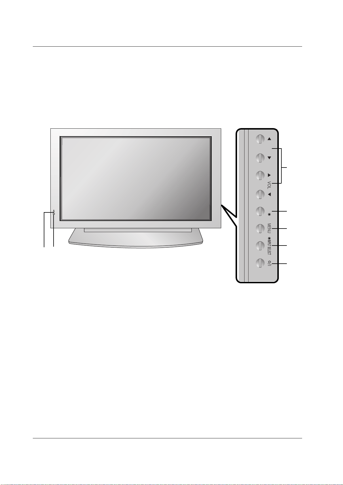
Location and Function of Controls
Location and Function of Controls
<Front Panel Controls>
42PM3MV/H series
OK
1. Power Button
Switches the set on from standby or off to standby.
2. Remote Control Sensor
3. Power Standby Indicator
Illuminates red in standby mode, Illuminates green when
the set is turned on
4. INPUT SELECT Button
5. MENU
Displays on screen menus one by one.
Exits the current menu.
Memorizes menu changes.
6. OK
Accepts your selection or displays the current mode.
7.
DD
/
EE
Selects a menu option.
FF
/
GG
(Volume Up/Down)
Increases/decreases sound level.
Adjusts menu settings.
1
4
5
6
7
3
2
Owner’s Manual 9
Introduction
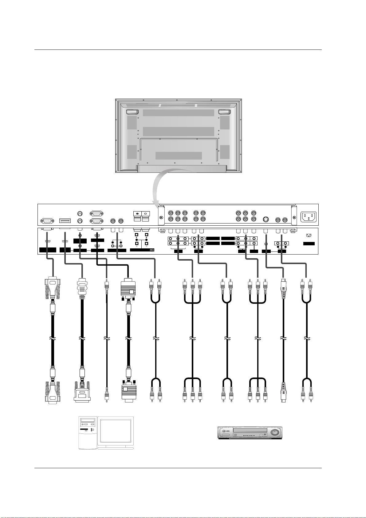
<Back Panel>
AC INPUT
AUDIO INPUT RGB INPUT
RGB OUTPUT
RS-232C INPUT
(CONTROL/SERVICE)
REMOTE
CONTROL
S-VIDEO
YP
B
P
R
VIDEO
R
L
VARIABLE AUDIO OUT
AUDIO
R
L
EXTERNAL SPEAKER
HDMI/DVI
(VIDEO INPUT
R
L
AUDIO
R
L
AUDIO
R
L
AUDIO VIDEO
COMPONENT INPUT 2
COMPONENT INPUT 1
MONITOR OUPUT
A/V INPUT
(MONO) (MONO)
Connection to PC
Connection to AV equipment
10 PLASMA MONITOR
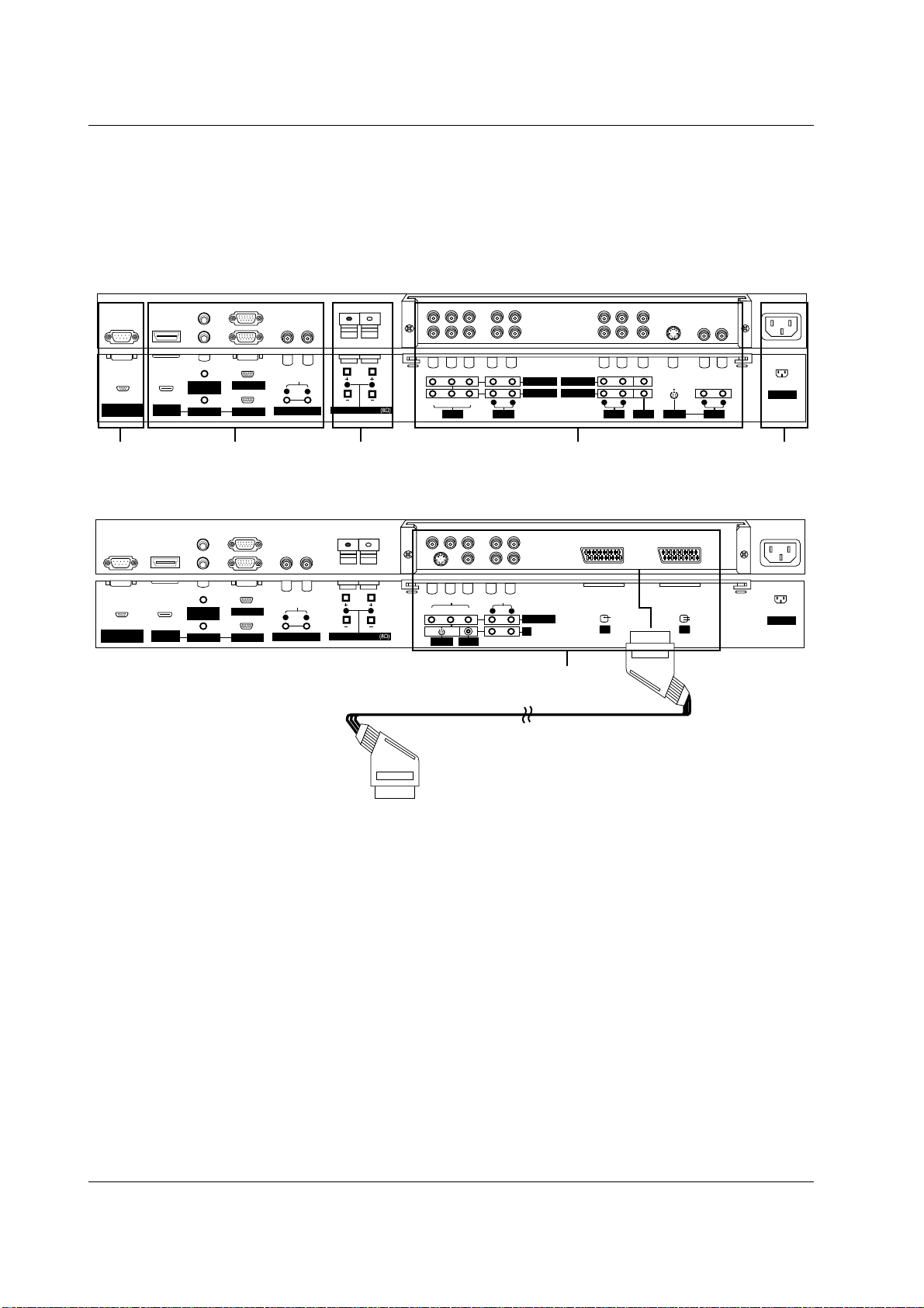
Introduction
<Back Panel>
AC INPUT
AUDIO INPUT RGB INPUT
RGB OUTPUT
RS-232C INPUT
(CONTROL/SERVICE)
REMOTE
CONTROL
YP
B
P
R
VIDEO
S-VIDEO
R
L
VARIABLE AUDIO OUT
AUDIO
R
L
EXTERNAL SPEAKER
HDMI/DVI
(VIDEO) INPUT
L
R
VIDEO
AUDIO
COMPONENT INPUT
AV3
(MONO)
AV1 AV2
AV1
RCA Type
Scart Type
4
AC INPUT
AUDIO INPUT RGB INPUT
RGB OUTPUT
RS-232C INPUT
(CONTROL/SERVICE)
REMOTE
CONTROL
S-VIDEO
YP
B
P
R
VIDEO
R
L
VARIABLE AUDIO OUT
AUDIO
R
L
EXTERNAL SPEAKER
HDMI/DVI
(VIDEO) INPUT
R
L
AUDIO
R
L
AUDIO
R
L
AUDIO VIDEO
COMPONENT INPUT 2
COMPONENT INPUT 1
MONITOR OUPUT
A/V INPUT
(MONO) (MONO)
1 2 345
1. RS-232C INPUT(CONTROL/SERVICE) PORT
Connect to the RS-232C port on a PC.
2. HDMI/DVI (VIDEO) / AUDIO INPUT / RGB INPUT SOCKETS
Connect the set output socket of the PERSONAL COMPUTER
to this socket.
Note: If you want to use RGB/DVI audio, we strongly recom-
mend that you use the cable that has a core, or the EMI Filter
core along with separate cable.
RGB OUTPUT SOCKET
You can watch the RGB signal on another set, connect RGB
OUTPUT to another set’s PC input port.
REMOTE CONTROL
VARIABLE AUDIO OUTPUT
3. EXTERNAL SPEAKER OUTPUT (8 ohm)
Connect to optional external speaker(s).
* For further information, refer to ‘Speaker & Speaker Stand’
manual.
4. COMPONENT / AUDIO INPUT SOCKETS
S-VIDEO / AUDIO (L/MONO) INPUT SOCKETS
VIDEO / AUDIO (L/MONO) INPUT SOCKETS
EURO SCART SOCKET
Connect the euro scart socket of the VCR to these sockets.
Note:
a. If you want to use the EURO scart cable, you have to use
the signal shielded Euro scart cable.
b. If you want to use your external hi-fi stereo system, turn off
the internal speakers of the set.
c. If the S-VIDEO(Y/C) signal is received through the Euro scart
socket 2 (AV 2), you must change to the S-Video 2 (Y/C) mode.
5. POWER CORD SOCKET
This set operates on an AC power. The voltage is indicated on
the Specifications page. Never attempt to operate the set on
DC power.
Location and Function of Controls
Location and Function of Controls
Owner’s Manual 11
Installation
External Equipment V
External Equipment V
iewing Setups
iewing Setups
Watching VCR (When the Interface board is installed.)
- When connecting the set with external equipments, match the colours of connecting ports (Video - yellow, Audio(L) - white,
Audio(R) -red).
- Connect the VIDEO INPUT socket(yellow) to the VIDEO INPUT socket of the set.
- If you have a mono VCR, connect the audio cable from the VCR to the AUDIO(L/MONO) input of the set.
- If you connect an S-VIDEO VCR to the S-VIDEO input, the picture quality is improved; compared to connecting a regular
VCR to the Video input.
- Or, connect the Euro scart socket of the VCR to the Euro scart socket of the set.
Avoid having a fixed image remain on the screen for a long period of time. Typically a frozen still picture from a VCR, 4:3
picture format or if a CH label is present; the fixed image may remain visible on the screen.
Use the orbiter function to avoid having a fixed image. (Refer to p.24)
1. Press INPUT button on the remote control and select AV , S-Video or (AV 1 , AV 2 , S-Video2 or AV 3 ).
(If both S-VIDEO and VIDEO sockets have been connected to the S-VHS VCR simultaneously, only the S-VIDEO can be
received.)
2. Insert a video tape into the VCR and press the PLAY button on the VCR. (See VCR owner’s manual)
Watching external AV source
(When the Interface board is installed.)
- When connecting the set with external equipments, match the colours of connecting ports.
- Or, connect the Euro scart socket of the VCR to the Euro scart socket of the set.
1. Press INPUT button on the remote control of the set to select
AV , S-Video or (AV 1 , AV 2 , S-Video2 or AV 3 ).
2. Operate the corresponding external equipment. (See external equipment operating guide.)
Watching Cable TV
(When the Interface board is installed.)
- After subscribing to a cable TV service from a local provider and installing a converter, you can watch cable TV programming.
This set cannot display TV programming without a TV tuner device or cable TV converter box connected to the set.
1. Press INPUT button on the remote control and select
AV , S-Video or (AV 1 , AV 2 , S-Video2 or AV 3 ).
2. Tune to cable service provided channels using the cable box.
• Component Input ports
You can get better picture quality if you con-
nect DVD player with component input ports
as below.
Component ports of the set
Y PB
PR
Video output ports
of DVD player
Y
Y
Y
Y
Pb
B-Y
Cb
PB
Pr
R-Y
Cr
PR
Watching DVD
(When the Interface board is installed.)
How to connect
- Connect DVD video inputs to Y, P
B
, P
R
of COMPONENT (DVD
INPUT) and audio inputs to Audio sockets of AUDIO INPUT.
- Or, connect the Euro scart socket of the VCR to the Euro scart
socket of the set.
How to use
1. Press INPUT or MULTIMEDIA button on the remote control of the
set to select Component or (Component1 or Component2).
2. Try this after turning on the DVD player.
(Refer to the DVD player's manual for operating instructions.)
12 PLASMA MONITOR
Installation
Connecting PC
- To enjoy vivid picture and sound, connect a PC to the set.
- Avoid keeping a fixed image on the set’s screen for a long period of time. The fixed image may become permanently
imprinted on the screen; use a screen saver when possible.
- Connect PC to the RGB INPUT(PC INPUT) or HDMI/DVI INPUT(DIGITAL RGB INPUT) port of the set; change the resolu-
tion output of PC accordingly.
- There might be a noise according to some resolution, vertical pattern, contrast or brightness in PC mode. Then change the
PC mode into other resolution or change the refresh rate into other rate or adjust the brightness and contrast on the menu
until the picture is clean. If the refresh rate of the PC graphic card can not be changed, change the PC graphic card or
consult it to the manufacturer of the PC graphic card.
- The synchronization input form for Horizontal and Vertical frequencies is separate.
Setup Instructions to Connect a PC to your set
- We recommend using 1024x768, 60Hz for the PC mode, they provide the best picture quality.
- If the resolution of PC is over UXGA, there will be no picture on the set.
- Connect the signal cable from the monitor output port of the PC to the RGB INPUT port of the set or the signal cable from
the DVI output port of the PC to the HDMI/DVI INPUT port on the set.
- Connect the audio cable from the PC to the Audio input on the set. (Audio cables are not included with the set).
- If using a sound card, adjust PC sound as required.
- This set apply a VESA Plug and Play Solution. The set provides EDID data to the PC system with a DDC protocol. The PC
adjusts automatically to use this set.
- DDC protocol is preset for RGB (Analog RGB), DVI (Digital RGB) mode.
- If required, adjust the set settings for Plug and Play functionally.
- If graphic card on the PC does not output analog and digital RGB simultaneously, connect only one of both RGB INPUT or
HDMI/DVI INPUT to display the PC on the set.
If graphic card on the PC output analog and digital RGB simultaneously, set the set to either RGB or HDMI; (the other
mode is set to Plug and Play automatically by the set.)
- DOS mode may not work depending on video card if using a DVI-I cable.
PC Setup
1. Turn on the PC and apply power to the set.
2. Turn on the display by pressing the POWER button on the set’s remote control.
3. Use the INPUT or MULTIMEDIA button on the remote control to select the RGB or HDMI input source.
4. Set the resolution output of the PC to SXGA or under (1280 x 1024, 60Hz). (Refer to p. 13)
Watching DTV Setup (option)
(When the Interface board is installed.)
- To watch digitally broadcast programs, purchase/connect a
digital set-top box.
How to connect a user-supplied Digital Set-Top Box
- Connect DTV set-top box video output to set COMPONENT
(DVD/DTV INPUT) or to the set RGB (PC/DTV INPUT) or to
the set HDMI/DVI (PC/DTV INPUT) connector depending on
your set-top box connectors.
- Connect DTV set-top box audio outputs to set AUDIO INPUT
jacks.
How to use
1. Turn on the a digital set-top box. (Refer to the owner’s manual
for the digital set-top box)
2. Use INPUT or MULTIMEDIA on the remote control to select
Component or (Component1 or Component2), RGB or
HDMI.
External Equipment V
External Equipment V
iewing Setups
iewing Setups
• DTV Input signal
480i
576i
480p
576p
720p
1080i
Mode
Terminal
Component
o
o
o
o
o
o
RGB (DTV)
x
x
o
o
o
o
HDMI (DTV)
x
x
o
o
o
o
Owner’s Manual 13
Installation
Displayable Monitor Specification
Displayable Monitor Specification
Displayable Monitor Specification
Displayable Monitor Specification
RGB / HDMI mode
42PM1M/H series
50PM1M/H series
60PZ9M/H series
Resolution
640x350
720x400
640x480
848x480
800x600
Horizontal
Frequency(KHz)
Vertical
Frequency(Hz)
852x480
832x624
1024x768
1360x768
1366x768
1152x864
1152x870
1280x960
1280x768
1280x1024
70.09
85.08
70.08
85.03
59.94
66.66
72.80
75.00
85.00
60.00
70.00
75.00
60.00
70.00
75.00
56.25
60.31
72.18
75.00
85.06
74.55
60.00
70.06
75.02
85.00
60.00
75.02
60.00
75.02
60.05
70.01
75.00
75.06
59.99
74.93
60.02
60.02
31.468
37.861
31.469
37.927
31.469
35.000
37.861
37.500
43.269
31.500
37.799
39.375
31.500
37.799
39.375
35.156
37.879
48.077
46.875
53.674
49.725
48.363
56.476
60.023
68.677
47.700
59.625
47.700
59.625
54.348
63.995
67.500
68.681
47.693
60.091
60.023
63.981
RGB / HDMI mode
Resolution
640x350
720x400
640x480
848x480
800x600
Horizontal
Frequency(KHz)
Vertical
Frequency(Hz)
852x480
832x624
1024x768
1152x864
1152x870
1280x960
1280x1024
70.09
85.08
70.08
85.03
59.94
66.66
72.80
75.00
85.00
60.00
70.00
75.00
60.00
70.00
75.00
56.25
60.31
72.18
75.00
85.06
74.55
60.00
70.06
75.02
85.00
60.05
70.01
75.00
75.06
60.02
60.02
31.468
37.861
31.469
37.927
31.469
35.000
37.861
37.500
43.269
31.500
37.799
39.375
31.500
37.799
39.375
35.156
37.879
48.077
46.875
53.674
49.725
48.363
56.476
60.023
68.677
54.348
63.995
67.500
68.681
60.023
63.981
42PM3MV/H series
14 PLASMA MONITOR
Installation
- HDMI
TM
, the HDMI logo and High-Definition Multimedia Interface are trademarks or registered trademarks of HDMI Licensing
LLC.
- This set can receive the High-Definition Multimedia Interface (HDMI) or Input of Digital Visual Interface(DVI).
- This set supports HDCP (High-bandwidth Digital Contents Protection) Protocol for the set (480p, 720p, 1080i) modes.
- When you Connect with HDMI/DVI Source Devices (DVD Player or Set Top Box or PC) supporting Auto HDMI/DVI func-
tion, automatically, support Plug & Play and then set the HDMI/DVI Source Devices (1280 x 720p) (or 42PM3MV/H series:
640 x 480p). After reading in HDMI/DVI Source Devices using Display Data Channel(DDC) Protocol, EDID stored in the set
is used. If HDMI/DVI Source Devices not supported Auto HDMI/DVI is been, the Resolution is set, manually.
- To get the best picture quality, adjust the DVD Player or Set Top Box output resolution to 1280 x 720p (or 42PM3MV/H series:
640 x 480p).
- To get the best picture quality, adjust the PC graphics card to 1024 x 768 (or 42PM3MV/H series: 640 x 480), 60Hz.
- When Source Devices have DVI Output Connector, you must connect audio with separated cable.
(Refer to <How to connect>)
How to connect
1. When Source Devices (DVD Player or Set Top Box) support HDMI.
- If Source Devices have HDMI Output Connector, Source Devices connect to the set with HDMI Cable .(not supplied with
the product).
- If Source Devices support Auto HDMI, automatically, Source Devices divert output resolution in 1280 x 720p (or
42PM3MV/H series: 640 x 480p). But if not, resolution divert Manually Setting for reference Manual of Source Devices.
- To get the best picture quality, adjust the DVD Player or Set Top Box output resolution to 1280 x 720p (or 42PM3MV/H
series: 640 x 480p).
- Because HDMI sends Digital Video and Audio with one cable, need not especial Audio Cable for using HDMI Cable.
2. When Source Devices (DVD Player or Set Top Box) supports DVI.
- If Source Devices have DVI Output Connector, Source Devices connect to the set with HDMI to DVI Cable (not supplied
with the product).
- If Source Devices support Auto DVI, automatically, Source Devices divert output resolution in 1280 x 720p (or 42PM3MV/H
series: 640 x 480p). But if not, resolution divert Manually Setting for reference Manual of Source Devices.
- To get the best picture quality, adjust the DVD Player or Set Top Box output resolution to 1280 x 720p (or 42PM3MV/H
series: 640 x 480p).
- In this case, Audio use other cable. When Source Devices have Analog Audio Output Connector, RGB/DVI Audio Input of
the set connect to Audio Cable (not supplied with the product). And then you can listen to normal Audio.
3. When PC supports DVI.
- If PC have DVI Output Connector, Source Devices connect to the set with HDMI to DVI Cable (not supplied with the prod-
uct).
- To get the best picture quality, adjust the PC graphics card to 1024 x 768 (or 42PM3MV/H series: 640 x 480), 60Hz.
- Use the the set’s HDMI/DVI (VIDEO) for video connections, depending on your PC connector.
- If the graphics card on the PC does not output analog RGB and DVI simultaneously, connect only one of either RGB Input
or HDMI/DVI Input to display the PC on the set.
- If the graphics card on the PC does output analog RGB and DVI simultaneously, the set to either RGB Input or HDMI/DVI
Input; (the other mode is set to Plug and Play automatically by the set.)
- Then, make the corresponding audio connections. If using a sound card, adjust the PC sound as required.
- In this case, Audio use other cable. When PC (or sound card of PC) have Analog Audio Output Connector, RGB/DVI Audio
Input of the set connect to Analog Audio Cable (not supplied with the product). And then you can listen to normal Audio.
Owner’s Manual 15
Installation
How to use
1. Connect the HDMI/DVI Source Devices(DVD Player or Set Top Box or PC) and the set.
2. Turn on the display by pressing the POWER button on the set and HDMI/DVI Source Devices remote control.
3. Select HDMI/DVI Input source in Main Input option of SPECIAL menu.
4. Check the image on your set. There may be noise associated with the resolution, vertical pattern, contrast or brightness
in HDMI/DVI Source Devices. If noise is present, change the HDMI/DVI Source Devices to another resolution, change
the refresh rate or adjust the brightness and contrast on the menu until the picture is clear. If the refresh rate of the PC
graphics card can not changed, change the PC graphics card or consult the manufacturer of the PC graphics card.
Notes:
- Depending on the graphics card, DOS mode may not work if you use a HDMI to DVI Cable.
- Avoid keeping a fixed image on the set screen for a long period of time. The fixed image may become permanently
imprinted on the screen. Use the Orbiter screen saver when possible.
- When Source Devices connected HDMI/DVI Input, output PC Resolution(VGA, SVGA, XGA), Position, Size may not fit to
Screen. As shown the lower picture, press the MENU button to adjust the screen Position of the set and contact an PC
graphics card service center.
- When Source Devices connected HDMI/DVI Input output the set Resolution(480p, 720p, 1080i), the set Display fit
EIA/CEA-861-B Specification to Screen. If not, refer to the Manual of HDMI/DVI Source Devices or contact your service
center.
- In case HDMI/DVI Source Devices is not connected Cable or poor cable connection, "No Signal" OSD display in
HDMI/DVI Input. And In case of Video Resolution not supported the set output in HDMI/DVI Source Devices, "No Signal"
OSD display. Refer to the Manual of HDMI/DVI Source Devices or contact your service center.
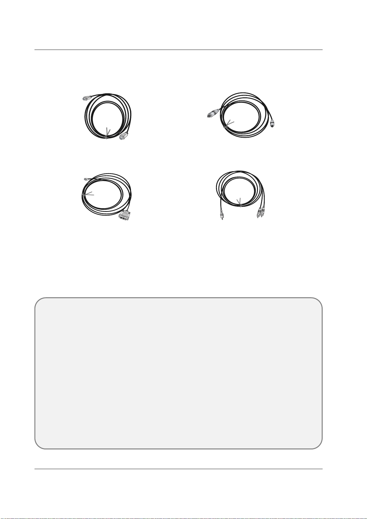
HDMI to DVI Cable
(not supplied with the product)
Analog Audio Cable (RCA type)
(not supplied with the product)
Analog Audio Cable (Stereo to RCA type)
(not supplied with the product)
HDMI Cable
(not supplied with the product)
Reference
Cable sample
16 PLASMA MONITOR
Installation
A
S
m
a
r
k
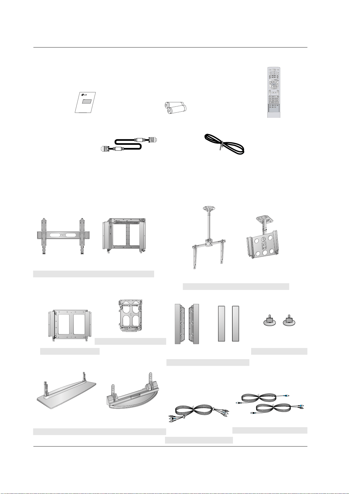
LG TV
Owner’s Manual
1.5V
1.5V
Alkaline batteries
Power Cord
INPUT
R
G
B
HDMI
I
N
D
E
X
M
I
X
H
O
L
D
M
O
D
E
P
O
S
I
T
I
O
N
R
E
V
E
A
L
S
-
V
I
D
E
O
2
A
V
1
S
IZ
E
T
I
M
E
A
V
3
M
E
N
U
T
E
X
T
/
SPLIT
ZOOM
ARC
OK
VOL VOL
PSM
SSM
SLEEP
I/II
COMPONENT
POWER
AV2
MUTE
M
?
LIST/
Q.VIEW/
Remote Control handset
- Optional extras can be changed or modified for quality improvement without any notification new optional extras can be
added.
- Contract your dealer for buying these items.
Optional Extras
Accessories
Accessories
42/50PM1M/H series
42PM3MV/H series
60PZ9M/H series
Tilt wall mounting bracket
404250 40 42 50
Video cables
Audio cables
42/50PM1M/H series
42PM3MV/H series
60PZ9M/H series
Ceiling mounting bracket
4
0
4
2
5
0
42
40
42/50PM1M/H series
42PM3MV/H series
60PZ9M/H series
Desktop stand
Speakers
42/50PM1M/H series
42PM3MV/H series
60PZ9M/H series
Wall mounting bracket
60PZ9M/H series
Desktop Speaker stand
Vertical Wall mounting bracket
D-sub 15 pin cable
(60PZ9M/H series only)
Owner’s Manual 17
Installation
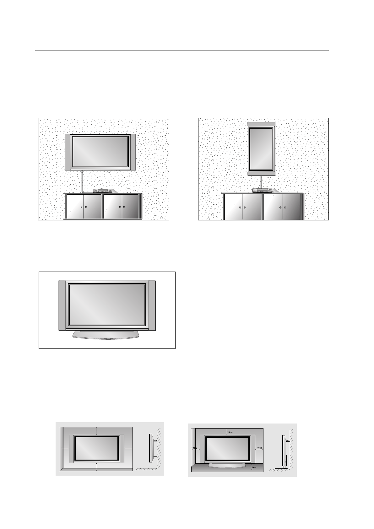
Installation Options
Installation Options
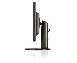
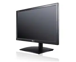
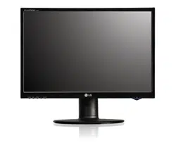
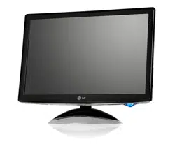
Desktop Pedestal Installation
• The set can be mounted on a desk as shown above.
(For further information, refer to the optional 'Desktop
Stand Installation and Setup Guide'.)
• Speakers and speaker stands shown are optional, and
are shown for example only.
• The set can be installed in different ways such as on a wall, or on a desktop etc.
• Install this set only in a location where adequate ventilation is available.
• This set is designed so that it can be mounted either horizontally or vertically.
Wall Mount: Horizontal Installation
• The set can be installed on a wall as shown above. (For
further information, refer to the optional ‘Wall Mounting
Bracket Installation and Setup Guide’.)
• Speakers are optional, and are shown for illustration only.
3cm
10cm
10cm
10cm
10cm
To Mount on a Wall
Wall mount minimum allowable clearances for ade-
quate ventilation.
To Install on a Desktop
Pedestal mount minimum allowable clearances for
adequate ventilation.
Wall Mount: Vertical Installation
• The set can be installed vertically on the wall as
shown above.(For further information, refer to the
optional ‘Wall Mounting Bracket Installation and Setup
Guide’.)
Caution: When installing the set vertically, the front
panel controls must be in the left-down side position as
shown above.
• Speakers are optional, and are shown for illustration
only.
• Note: To use the set in a vertical orientation, the
source's image must also be in a vertical format.

18 PLASMA MONITOR
Operation
On-Screen Menu Language Selection (option)
On-Screen Menu Language Selection (option)
- The menus can be shown on the screen in the selected language. First select your language.
1. Press the MENU button and then use
DD
/
EE
button to select the SPECIAL menu.
2. Press the
GG
button and then use
DD
/
EE
button to select Language.
3. Press the
GG
button and then use
DD
/
EE
button to select your desired language.
From this point on, the on-screen menus will be shown in the language of your choice.
4.
Repeatedly press the MENU button to return to normal viewing.
T
T
urning on the Set
urning on the Set
- When using the remote control, aim it at its sensor on the set.
Turning on the set just after installation
Turning on the set (power cord is still connected)
1. Connect power cord correctly.
2. Press the ON/OFF button on the set. At this moment, the set is switched to standby mode. Press the INPUT
SELECT button on the set or press the POWER, INPUT, MULTIMEDIA,
DD
/
EE
or NUMBER button on the remote
control and then the set will switch on.
• Press the ON/OFF button on the set to turn the set on.
1. If the set was turned off with the ON/OFF button on the set
2. If the set was turned off with the remote control and the ON/OFF button on the set
• Press the ON/OFF button on the set and then press the INPUT SELECT button on the set or press the POWER,
INPUT, MULTIMEDIA,
DD
/
EE
or NUMBER button on the remote control to turn the set on.
42/50PM1M/H series / 60PZ9M/H series
42PM3MV/H series
Turning on the set just after installation
Turning on the set (power cord is still connected)
1. Connect power cord correctly, the set is switched to standby mode.
2. Press the
rr
/ I, INPUT SELECT or
DD
/
EE
button on the set or press the POWER, INPUT, MULTIMEDIA,
DD
/
EE
or
NUMBER button on the remote control and then the set will switch on.
If the set was turned off with the remote control power button and the
rr
/ I button on the set
• Press the
rr
/ I, INPUT SELECT or
DD
/
EE
button on the set or press the POWER, INPUT, MULTIMEDIA,
DD
/
EE
or
NUMBER button on the remote control to turn the set on.
Owner’s Manual 19
Operation
Picture Menu Options
Picture Menu Options
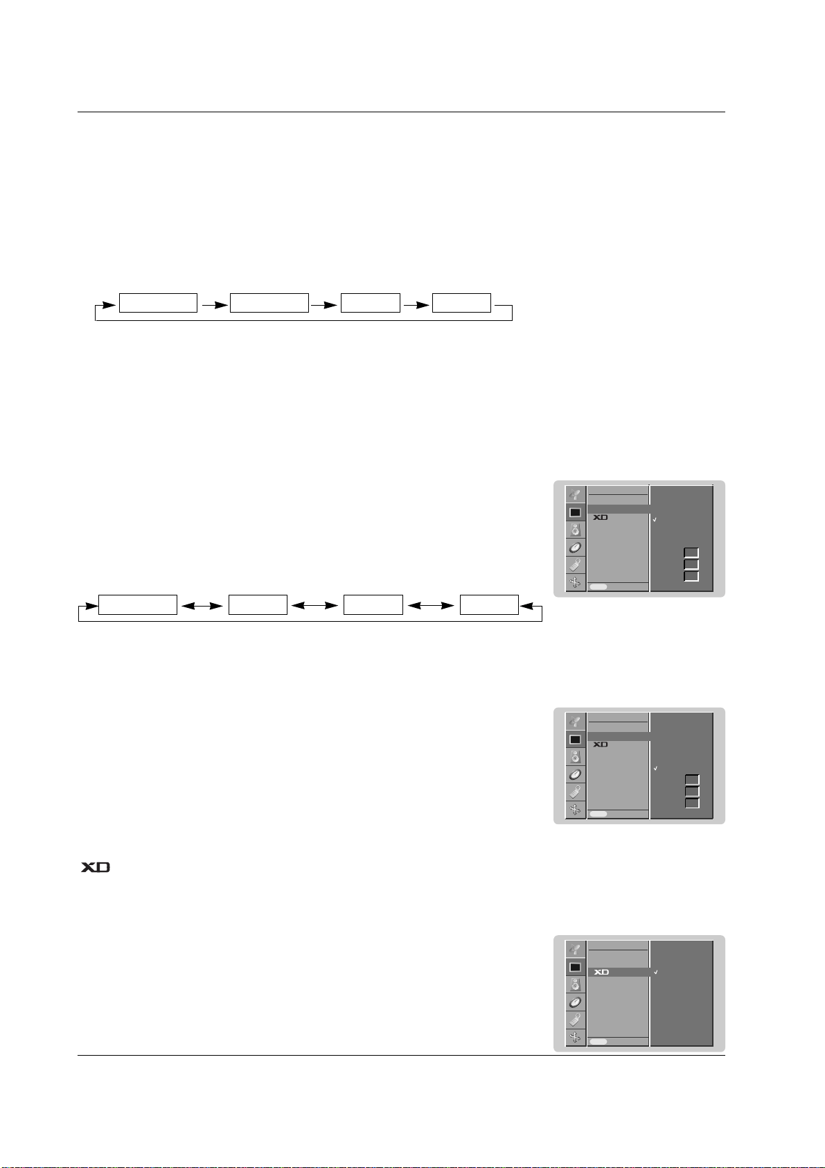
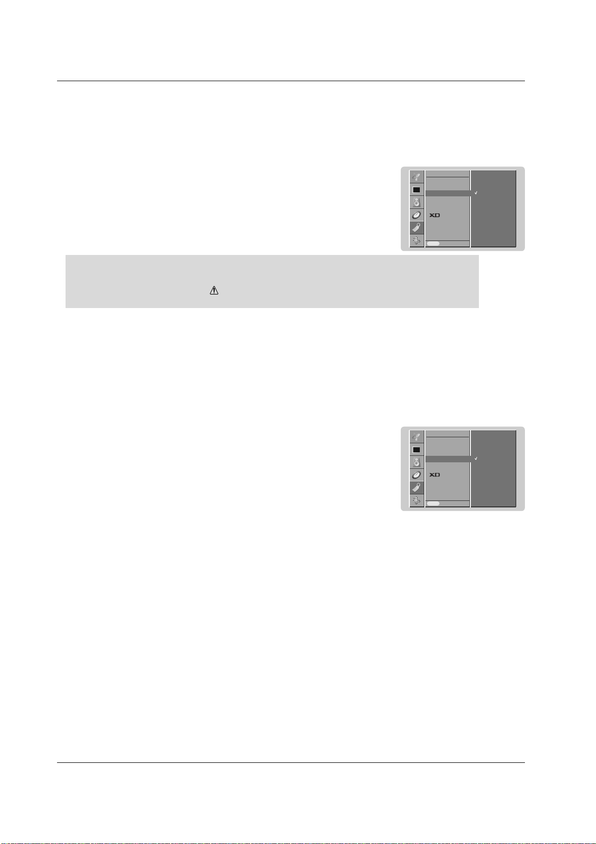
1. Press the PSM button
PSM (Picture Status Memory)
- This function adjusts the set to the best picture appearance.
- When adjusting picture options (contrast, brightness, colour, sharpness and tint (NTSC input only)) manually, PSM
is automatically changed to
User
.
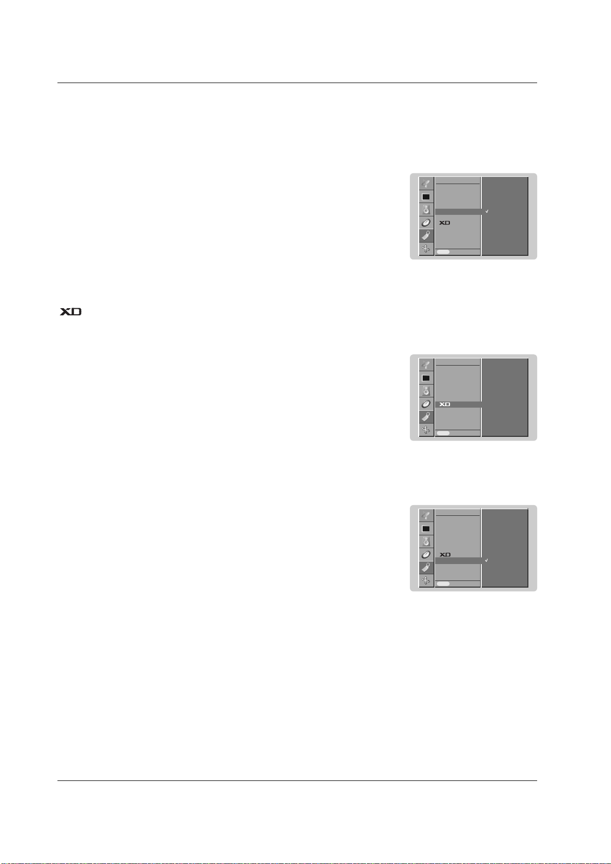
- You can enjoy the vivid and hi-definition picture with LG’s excellent Digital Reality processor technology.
- It’s not available to use this function in RGB[PC], HDMI[PC] mode.
- When selecting picture options (
Dynamic
,
Standard
and
Mild
) in PICTURE menu,
XD
is automatically changed
to
On
.
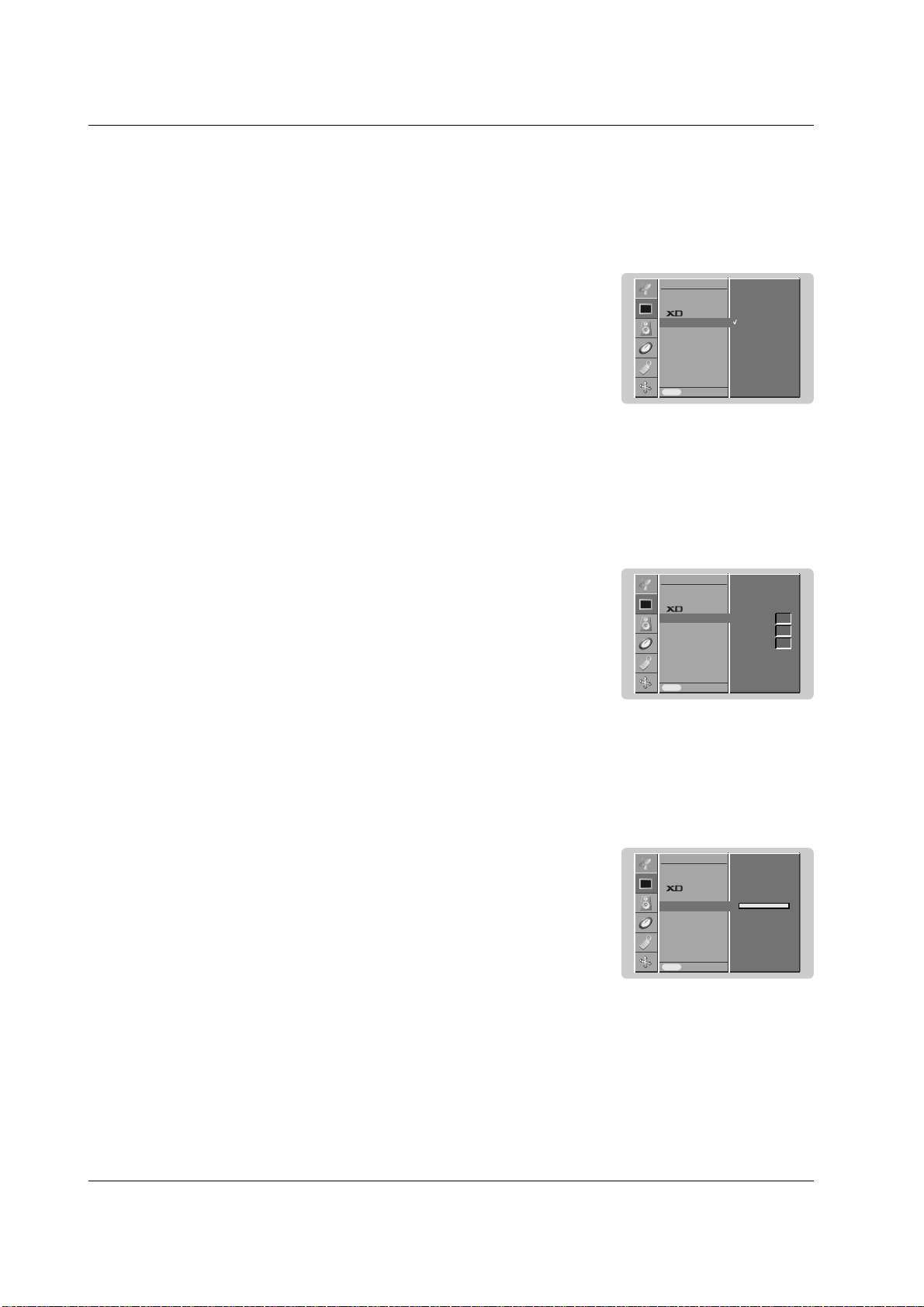
1. Press the MENU button and then use
DD
/
EE
button to select the PICTURE menu.
2. Press the
GG
button and then use
DD
/
EE
button to select
XD
.
3. Press the
GG
button and then use
DD
/
EE
button to select
On
or
Off
.
4.
Repeatedly press the MENU button to return to normal viewing.
• Each press of the PSM button changes the screen display as shown below.
• You can also select
Dynamic
,
Standard
,
Mild
or
User
in the PICTURE menu.
• Picture options
Dynamic
,
Standard
and
Mild
are preset and programmed for good picture quality at
the factory and cannot be changed.
Dynamic Standard Mild User
- To initialize values (reset to default settings), select the
Normal
option.
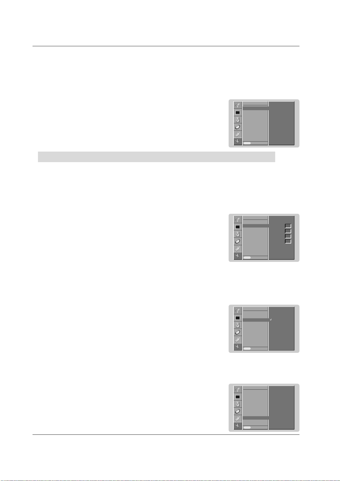
1. Press the MENU button and then use
DD
/
EE
button to select the PICTURE menu.
2. Press the
GG
button and then use
DD
/
EE
button to select
CSM
.
3. Press the
GG
button and then use
DD
/
EE
button to select the desired colour tempera-
ture.
4.
Repeatedly press the MENU button to return to normal viewing.
CSM (Color Status Memory)
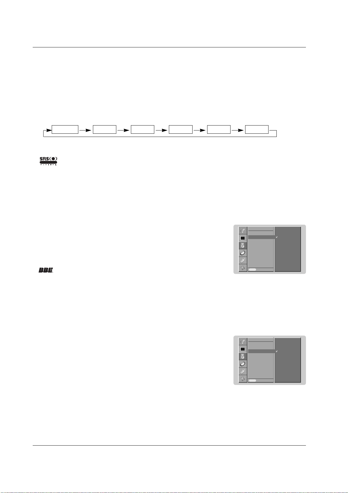
- You can adjust red, green, or blue to any colour temperature you prefer.
1. Press the MENU button and then use
DD
/
EE
button to select the PICTURE menu.
2. Press the
GG
button and then use
DD
/
EE
button to select
CSM
.
3. Press the
GG
button and then use
DD
/
EE
button to select
User
.
4. Press the
GG
button and then use
FF
/
GG
button to make appropriate adjustments.
5.
Repeatedly press the MENU button to return to normal viewing.
Manual Colour Temperature Control
• Each press of
DD
/
EE
button changes the screen display as shown below.
Cool Normal Warm User
PSM
CSM
ACM
Contrast 100
Brightness 60
Colour 50
Sharpness 50
Prev.
PICTURE
CSM
GG
Menu
Cool
Normal
Warm
User
Red
Green
Blue
0
0
0
PSM
CSM
ACM
Contrast 100
Brightness 60
Colour 50
Sharpness 50
Prev.
PICTURE
CSM
GG
Menu
Cool
Normal
Warm
User
Red
Green
Blue
0
0
0
PSM
CSM
ACM
Contrast 100
Brightness 60
Colour 50
Sharpness 50
Prev.
PICTURE
Menu
On
Off
GG
20 PLASMA MONITOR
Operation
1. Press the MENU button and then use
DD
/
EE
button to select the PICTURE menu.
2. Press the
GG
button and then use
DD
/
EE
button to select
sRGB
.
3. Press the
GG
button and then use
DD
/
EE
button to select
On
or
Off
.
4.
Repeatedly press the MENU button to return to normal viewing.
sRGB (RGB[PC], HDMI[PC] mode only)
1. Press the MENU button and then use
DD
/
EE
button to select the PICTURE menu.
2. Press the
GG
button and then use
DD
/
EE
button to select the desired picture option.
3. Press the
GG
button and then use
FF
/
GG
button to make appropriate adjustments.
4.
Repeatedly press the MENU button to return to normal viewing.
Manual Picture Control
- You can adjust picture contrast, brightness, colour, sharpness and tint (NTSC input only) to the levels you prefer.
- It’s not available to use colour, sharpness function in RGB[PC], HDMI[PC] mode.
- In the broadcasting system PAL/SECAM, the picture item Tint doesn’t work.
- Adjust the
ACM to select the desired skin colour option.
- This function is not available for use in RGB[PC], HDMI[PC] mode.
- It’s not available to use this function in
XD Off
mode.
1. Press the MENU button and then use
DD
/
EE
button to select the PICTURE menu.
2. Press the
GG
button and then use
DD
/
EE
button to select
ACM
.
3. Press the
GG
button and then use
FF
/
GG
button to make appropriate adjustments.
4.
Repeatedly press the MENU button to return to normal viewing.
ACM (Active Color Management)
- When the set was connected to external equipment with sRGB function, It’s adjusted a colour difference to display
the equal image each other.
PSM
CSM
ACM
Contrast 100
Brightness 60
Prev.
PICTURE
Menu
On
Off
sRGB
GG
PSM
CSM
ACM
Contrast 100
Brightness 60
Colour 50
Sharpness 50
Prev.
PICTURE
Menu
ACM
GG
Fleshtone
Greentone
Bluetone
0
0
0
PSM
CSM
ACM
Contrast 100
Brightness 60
Colour 50
Sharpness 50
Prev.
PICTURE
Menu
Contrast 100
GG
Picture Menu Options
Picture Menu Options
Owner’s Manual 21
Operation
Sound Menu Options
Sound Menu Options
1. Press the SSM button.
2. Press the SSM button to select your desired sound.
SSM (Sound Status Memory)
- This function lets you enjoy the best sound without any special adjustment because the set automatically selects the
appropriate sound option based on the program content.
- When adjusting sound options (treble and bass) manually, SSM is automatically changed to
User
.
- This feature maintains an equal volume level; even if you change channels.
1. Press the MENU button and then use
DD
/
EE
button to select the SOUND menu.
2. Press the
GG
button and then use
DD
/
EE
button to select
AV L
.
3. Press the
GG
button and then use
DD
/
EE
button to select
On
or
Off
.
4.
Repeatedly press the MENU button to return to normal viewing.
AVL (Auto Volume Leveler)
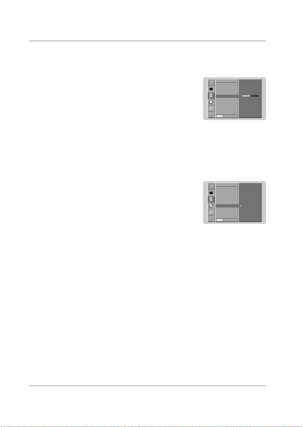
- BBE High Definition Sound restores clarity and presence for better speech intelligibility and musical realism.
Manufactured under license from BBE Sound, Inc.
1. Press the MENU button and then use
DD
/
EE
button to select the SOUND menu.
2. Press the
GG
button and then use
DD
/
EE
button to select
BBE
.
3. Press the
GG
button and then use
DD
/
EE
button to select
On
or
Off
.
4.
Repeatedly press the MENU button to return to normal viewing.
BBE
• You can also select
SRS TSXT
,
Flat
,
Music
,
Movie
,
Sports
or
User
in the SOUND menu.
• The sound
SRS TSXT
,
Flat
,
Music
,
Movie
and
Sports
are programmed for good sound reproduction at the factory
and cannot be changed.
SRS TSXT Flat Music Movie Sports User
- is a trademark of SRS Labs, Inc.
- TruSurround XT technology is incorporated under license from SRS Labs, Inc.
R
TruSurround XT
SSM
BBE
AVL
Balance 0
Treble 50
Bass 50
Speaker
Prev.
SOUND
Menu
On
Off
BBE
GG
SSM
BBE
AVL
Balance 0
Treble 50
Bass 50
Speaker
Prev.
SOUND
Menu
On
Off
AVL
GG
22 PLASMA MONITOR
Operation
- You can adjust internal speaker status.
- In COMPONENT, RGB[PC] and HDMI[PC] mode, speaker/variable audio can be output even though there is no video
signal.
1. Press the MENU button and then use
DD
/
EE
button to select the SOUND menu.
2. Press the
GG
button and then use
DD
/
EE
button to select
Speaker
.
3. Press the
GG
button and then use
DD
/
EE
button to select
On
or
Off
.
4.
Repeatedly press the MENU button to return to normal viewing.
Speaker
1.
Press the MENU button and then use
DD
/
EE
button to select the SOUND menu.
2. Press the
GG
button and then use
DD
/
EE
button to select the desired sound item.
3. Press the
GG
button and then use
FF
/
GG
button to make appropriate adjustments.
4.
Repeatedly press the MENU button to return to normal viewing.
Note : Treble, Bass or BBE aren’t suitable to use SRS TSXT.
Adjusting Sound Control
SSM
BBE
AVL
Balance 0
Treble 50
Bass 50
Speaker
Prev.
SOUND
Menu
Treble 50
GG
SSM
BBE
AVL
Balance 0
Treble 50
Bass 50
Speaker
Prev.
SOUND
Menu
On
Off
Speaker
GG
Sound Menu Options
Sound Menu Options
Owner’s Manual 23
Operation
T
T
ime Menu Options
ime Menu Options
a.To check the remaining sleep time, press the SLEEP button once.
b.To cancel the sleep time, repeatedly press the SLEEP button until the display
--- Min
appears.
c. If you turn the set off after setting the sleep timer, the setting will be erased.
Sleep Timer
- Sleep timer turns the set off at the preset time.
- Press the SLEEP button to select the number of minutes. The display
--- Min
will appear on the screen, fol-
lowed by
10
,
20
,
30
,
60
,
90
,
120
,
180
and
240
minutes. The timer begins to count down from the number of minutes
selected.
z
z
z
z
- Timer function operates only if current time has been already set.
- Off Timer function overrides on Timer function if they are set to the same time.
- The set must be in standby mode for the On Timer to work.
- To cancel Off/On time function
Press the
DD
/
EE
button to select Off in step 3.
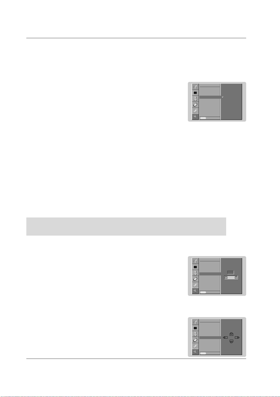
Setting the On/Off Timer
1. Press the MENU button and then use
DD
/
EE
button to select the TIME menu.
2. Press the
GG
button and then use
DD
/
EE
button to select
Off time
or
On time
.
3. Press the
GG
button and then use
DD
/
EE
button to select
On
.
4. Press the
GG
button and then use
DD
/
EE
button to adjust the hour.
5. Press the
GG
button and then use
DD
/
EE
button to adjust the minute.
6. Only
On time
function; Press the
GG
button and then use
DD
/
EE
button to adjust vol-
ume level.
7.
Repeatedly press the MENU button to return to normal viewing.
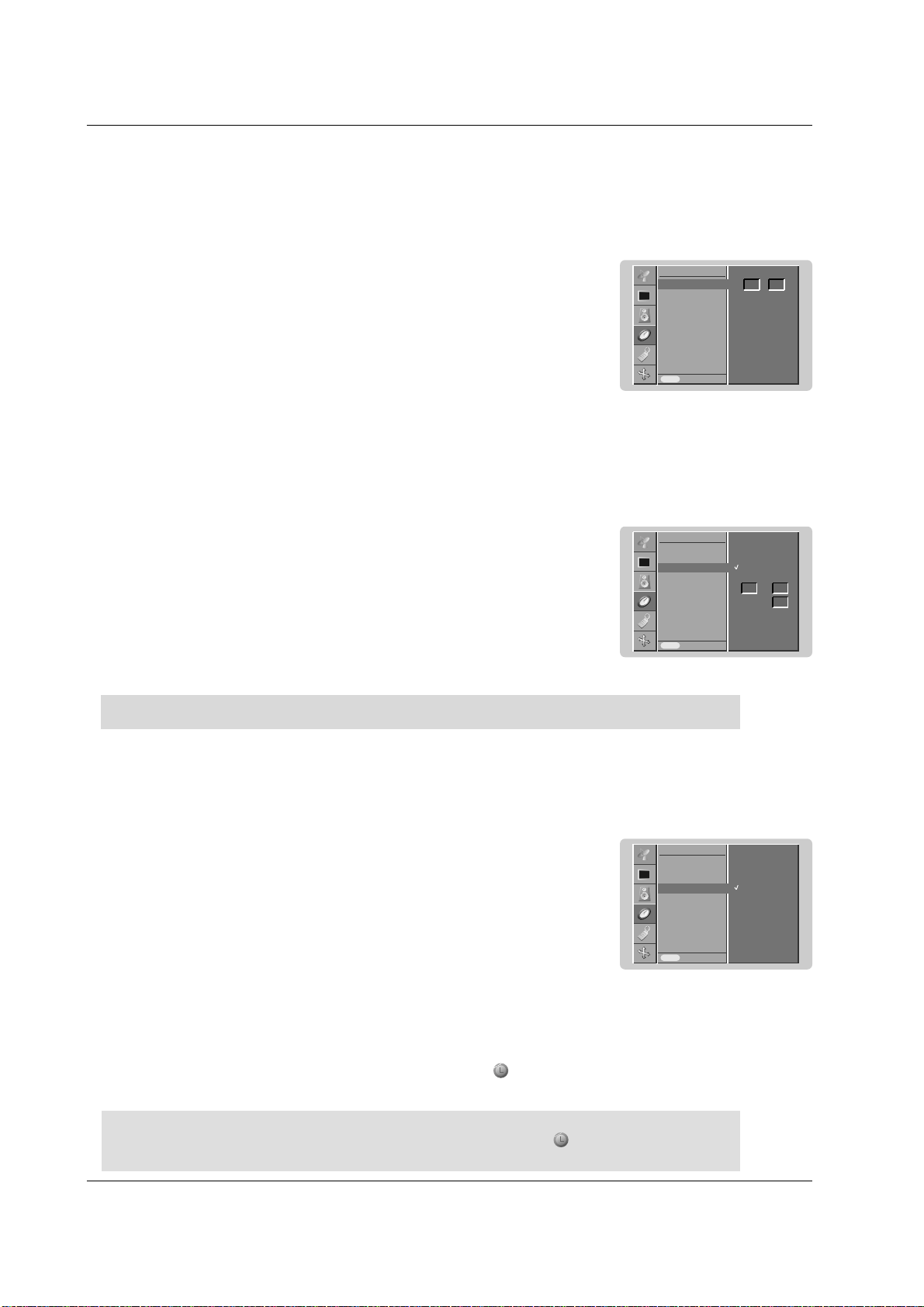
Auto Sleep
- If there is no input signal, the set turn off automatically after 10 minutes.
1. Press the MENU button and then use
DD
/
EE
button to select the TIME menu.
2. Press the
GG
button and then use
DD
/
EE
button to select
Auto sleep
.
3. Press the
GG
button and then use
DD
/
EE
button to select
On
or
Off
.
4.
Repeatedly press the MENU button to return to normal viewing.
Setting the Clock
- If current time setting is erased by a power failure or if the set is unplugged, reset the clock.
1. Press the MENU button and then use
DD
/
EE
button to select the TIME menu.
2. Press the
GG
button and then use
DD
/
EE
button to select
Clock
.
3. Press the
GG
button and then use
DD
/
EE
button to adjust the hour.
4. Press the
GG
button and then use
DD
/
EE
button to adjust the minute.
5.
Repeatedly press the MENU button to return to normal viewing.
Clock
Off time
On time
Auto sleep
Prev.
TIME
Menu
Clock
GG
:- - - -
Clock
Off time
On time
Auto sleep
Prev.
TIME
Menu
On time
GG
:12 00
30
On
Off
Volume
Clock
Off time
On time
Auto sleep
Prev.
TIME
Menu
Auto sleep
GG
On
Off
24 PLASMA MONITOR
Operation
Special Menu Options
Special Menu Options
Child Lock
- The set can be set up so that it can only be used with the remote control.
- This set programmed to remember which option it was last set to even if you turn the set off.
- In
Child lock
‘
On
’, if the set is turned off, press the INPUT SELECT button on the set or POWER or INPUT but-
ton on the remote control.
- With the
Child lock On
, the display ‘
Child lock on
’ appears on the screen if any button on the front panel is
pressed while viewing the set.
1. Press the MENU button and then
DD
/
EE
button to select the SPECIAL menu.
2. Press the
GG
button and then
DD
/
EE
button to select
Child lock
.
3. Press the
GG
button and then
DD
/
EE
button to select
On
or
Off
.
4.
Repeatedly press the MENU button to return to normal viewing.
ISM (Image Sticking Minimization) Method
- Frozen still picture from a PC/video game displayed on the screen for prolonged periods will result in an ghost
image remaining even when you change the image. Avoid allowing a fixed image to remain on the set's screen for
a long period of time.
1. Press the MENU button and then use
DD
/
EE
button to select the SPECIAL menu.
2. Press the
GG
button and then
DD
/
EE
button to select
ISM Method
.
3. Press the
GG
button and then
DD
/
EE
button to select either
Normal
,
White wash
,
Orbiter
or
Inversion
. If you unnecessary to set this function, set
Normal
.
•
White Wash
:
White Wash removes permanent images from the screen.
Note: An excessive permanent image may be impossible to clear entirely with White
Wash.
•
Orbiter
:
Orbiter may help prevent ghost images. However, it is best not to allow any fixed
image to remain on the screen. To avoid a permanent image on the screen, the
screen will move every 2 minutes.
•
Inversion
:
This is the function to invert the panel color of the screen. The panel color is automat-
ically inverted every 30 minutes.
4.
Repeatedly press the MENU button to return to normal viewing.
Input
Language
Child lock
ISM Method
Low power
Set ID
Demo
OSD Rotate
Prev.
SPECIAL
Menu
Child lock
GG
On
Off
Input
Language
Child lock
ISM Method
Low power
Set ID
Demo
OSD Rotate
Prev.
SPECIAL
Menu
ISM Method
GG
Normal
White wash
Orbiter
Inversion
Owner’s Manual 25
Operation
- This is the function to reduce the power consumption of the set.
Low Power
1. Press the MENU button and then use
DD
/
EE
button to select the SPECIAL menu.
2. Press the
GG
button and then use
DD
/
EE
button to select
Low power
.
3. Press the
GG
button and then use
DD
/
EE
button to select
On
or
Off
.
4.
Repeatedly press the MENU button to return to normal viewing.
- Use it to see the difference between XD demo on and XD Demo off.
- This function is not available for use in RGB[PC], HDMI[PC] mode.
- It’s not available to use this function in Rotate mode.
Demo
1. Press the MENU button and then use
DD
/
EE
button to select the SPECIAL menu.
2. Press the
GG
button and then use
DD
/
EE
button to select
XD Demo
.
3. Press the
GG
button to begin
XD Demo
.
4. To stop
XD Demo
, press the MENU button.
Input
Language
Child lock
ISM Method
Low power
Set ID
Demo
OSD Rotate
Prev.
SPECIAL
Menu
Low power
GG
On
Off
Input
Language
Child lock
ISM Method
Low power
Set ID
Demo
OSD Rotate
Prev.
SPECIAL
Menu
Demo
GG
To start
Menu Rotation for Vertical Viewing (option)
1. Press the MENU button and then use
DD
/
EE
button to select the SPECIAL menu.
2. Press the
GG
button and then use
DD
/
EE
button to select
OSD Rotate
.
3. Press the
GG
button and then use the
DD
/
EE
button to select
Normal
or
Rotate
.
• Select
Normal
: if the set is installed horizontally.
• Select
Rotate
: if the set is installed vertically.
4.
Repeatedly press the MENU button to return to normal viewing.
Input
Language
Child lock
ISM Method
Low power
Set ID
Demo
OSD Rotate
Prev.
SPECIAL
Menu
OSD Rotate
GG
Normal
Rotate
26 PLASMA MONITOR
Operation
Screen Menu Options
Screen Menu Options
Auto adjustment
- Automatically adjusts picture position and minimizes image shaking.
- This function works in the following mode: RGB [PC] mode only
- Although the image is still not correct, your set is functioning properly but needs further adjustment.
- The Auto config. functions don’t need to be run for HDMI mode.
1. Press the MENU button and then use
DD
/
EE
button to select the SCREEN menu.
2. Press the
GG
button and then use
DD
/
EE
button to select Auto config..
3. Press the
GG
button to start Auto config..
• When
Auto config. has finished, OK will be shown on screen.
• If the position of the image is still not correct, try Auto adjustment again.
4. If picture needs to be adjusted more after Auto adjustment in RGB (PC), you can adjust
the
Manual config..
5. Repeatedly press the MENU button to return to normal viewing.
Manual Configure
- If the picture isn’t clear after auto adjustment and especially that characters are still trembling, adjust the picture phase
manually.
- To correct the screen size, adjust Clock.
- This function works in the following mode:
RGB[PC], RGB[DTV], HDMI[DTV], COMPONENT[DTV] mode only
- It’s not available to use Phase, Clock function in RGB[DTV], HDMI[DTV], COMPONENT[DTV] mode.
1. Press the MENU button and then
DD
/
EE
button to select the SCREEN menu.
2. Press the
GG
button and then
DD
/
EE
button to select Manual config..
3. Press the
GG
button and then
DD
/
EE
button to select Phase, Clock, H-Position or
V-Position.
4. Press the
FF
/
GG
button to make appropriate adjustments.
5.
Repeatedly press the MENU button to return to normal viewing.
Selecting Wide VGA/XGA mode
- To see a normal picture, match the resolution of RGB mode and selection of VGA/XGA mode.
- In some models, it’s not available to selection of XGA mode.
- This function works in the following mode: RGB[PC] mode only
1. Press the MENU button and then use
DD
/
EE
button to select the SCREEN menu.
2. Press the
GG
button and then use
DD
/
EE
button to select VGA Mode (or XGA Mode).
3. Press the
GG
button and then use
DD
/
EE
button to select the desired VGA/XGA resolution.
4.
Repeatedly press the MENU button to return to normal viewing.
Auto config.
Manual config.
VGA Mode
ARC
Zoom +/-
Position
Cinema
NR
Reset
Prev.
SCREEN
Menu
Auto config.
GG
To set
Auto config.
Manual config.
VGA Mode
ARC
Zoom +/-
Position
Cinema
NR
Reset
Prev.
SCREEN
Menu
Manual config.
GG
Phase
Clock
H-Position
V-Position
0
0
0
0
Auto config.
Manual config.
VGA Mode
ARC
Zoom +/-
Position
Cinema
NR
Reset
Prev.
SCREEN
Menu
VGA Mode
GG
640x480
848x480
852x480
Initializing (Reset to original factory value)
This function operates in current mode.
To initialize the adjusted value
1. Press the MENU button and then
DD
/
EE
button to select the SCREEN menu.
2. Press the
GG
button and then
DD
/
EE
button to select Reset.
3. Press the
GG
button.
• You can initialize Phase, Clock, H-Position, V-Position, Position and Zoom +/-.
Auto config.
Manual config.
VGA Mode
ARC
Zoom +/-
Position
Cinema
NR
Reset
Prev.
SCREEN
Menu
Reset
GG
To set
Owner’s Manual 27
Operation
Screen Position
- You are available to this function after adjusting Zoom +/-.
1. Press the MENU button and then
DD
/
EE
button to select the SCREEN menu.
2. Press the
GG
button and then
DD
/
EE
button to select Position.
3. Press the
GG
button and then
DD
/
EE
or
FF
/
GG
button to adjust the position.
4.
Repeatedly press the MENU button to return to normal viewing.
- You can only select 4:3 and 16:9 (Wide) in RGB[PC], HDMI[PC] mode only.
- You can only select 4:3, 16:9 (Wide) and Zoom in RGB[DTV], HDMI[DTV], Component [DTV] mode only.
- You can only select Spectacle, Full, 4:3, 16:9 (Wide), 14:9 and Zoom in Component [480i/576i] mode only.
- There might be uncomfortable in full mode. Then change into other mode.
1. Press the MENU button and then use
DD
/
EE
button to select the SCREEN menu.
2. Press the
GG
button and then use
DD
/
EE
button to select ARC.
3. Press the
GG
button and then use
DD
/
EE
button to select Spectacle, Full (option),
Original, 4:3, 16:9, 14:9 or Zoom.
• Spectacle
When your TV receives the wide screen signal, following selection will lead you to adjust
the picture horizontally, in non-linear proportion, to fill the entire screen.
• Full (option)
When your TV receives the wide screen signal, following selection will lead you to adjust
the picture horizontally or vertically, in a linear proportion, to fill the entire screen fully.
• Original
When your TV receives the wide screen signal, it will be automatically changed to the
picture format to be sent.
• 4:3
Following selection will lead you to view a picture with an original 4:3 aspect ratio, with
gray bars appearing at both the left and right sides.
• 16:9 (Wide)
Following selection will lead you to adjust the picture horizontally, in a linear proportion,
to fill the entire screen (useful for viewing 4:3 formatted DVDs).
• 14:9
You can enjoy the picture format of 14:9 or general TV programme through the 14:9
mode. The screen 14:9 is viewed just like that the screen 4:3 is magnified to the left /
right.
• Zoom
Following selection will lead you to view the picture without any alternation, while filling
the entire screen. However, the top and bottom portions of the picture will be cropped.
4. Repeatedly press the MENU button to return to normal viewing.
Setting Picture Format
- You can watch the screen in various picture formats;
Spectacle
, Full (option), Original, 4:3, 16:9 (Wide), 14:9 and
Zoom.
Auto config.
Manual config.
VGA Mode
ARC
Zoom +/-
Position
Cinema
NR
Reset
Prev.
SCREEN
Menu
ARC
GG
Spectacle
Full
Original
4:3
16:9
14:9
Zoom
- When enlarging or reducing the picture, the screen may be display unnatural picture.
Picture Size Zoom
1. Press the MENU button and then
DD
/
EE
button to select the SCREEN menu.
2. Press the
GG
button and then
DD
/
EE
button to select Zoom +/-.
3. Press the
GG
button and then
FF
/
GG
button to make appropriate adjustments.
4.
Repeatedly press the MENU button to return to normal viewing.
Auto config.
Manual config.
VGA Mode
ARC
Zoom +/-
Position
Cinema
NR
Reset
Prev.
SCREEN
Menu
Zoom +/-
GG
100
%
FF GG
Auto config.
Manual config.
VGA Mode
ARC
Zoom +/-
Position
Cinema
NR
Reset
Prev.
SCREEN
Menu
Position
GG
DD
FF
GG
EE
28 PLASMA MONITOR
Operation
NR (Noise Reduction)
1. Press the MENU button and then use
DD
/
EE
button to select the SCREEN menu.
2. Press the
GG
button and then use
DD
/
EE
button to select NR.
3. Press the
GG
button and then use
DD
/
EE
button to select 3D NR or MPEG NR.
4. Repeatedly press the MENU button to return to normal viewing.
1. Press the MENU button and then use
DD
/
EE
button to select the SCREEN menu.
2. Press the
GG
button and then use
DD
/
EE
button to select Cinema.
3. Press the
GG
button and then use
DD
/
EE
button to select
On
or
Off
.
4. Repeatedly press the MENU button to return to normal viewing.
Cinema
- When you watch the movie, this function adjusts the set to the best picture appearance.
- This function works in the following mode:
AV, S-VIDEO, COMPONENT 480i/576i.
Auto config.
Manual config.
VGA Mode
ARC
Zoom +/-
Position
Cinema
NR
Reset
Prev.
SCREEN
Menu
Cinema
GG
On
Off
Auto config.
Manual config.
VGA Mode
ARC
Zoom +/-
Position
Cinema
NR
Reset
Prev.
SCREEN
Menu
NR
GG
3D NR
MPEG NR
0
0
- You can select 3D NR or MPEG NR to reduce the picture noise which may appear on the screen during watching
the TV.
- This function is not available for use in RGB[PC], HDMI[PC] mode.
- 3D NR is not available for use in RGB, HDMI, COMPONENT[DTV] mode.
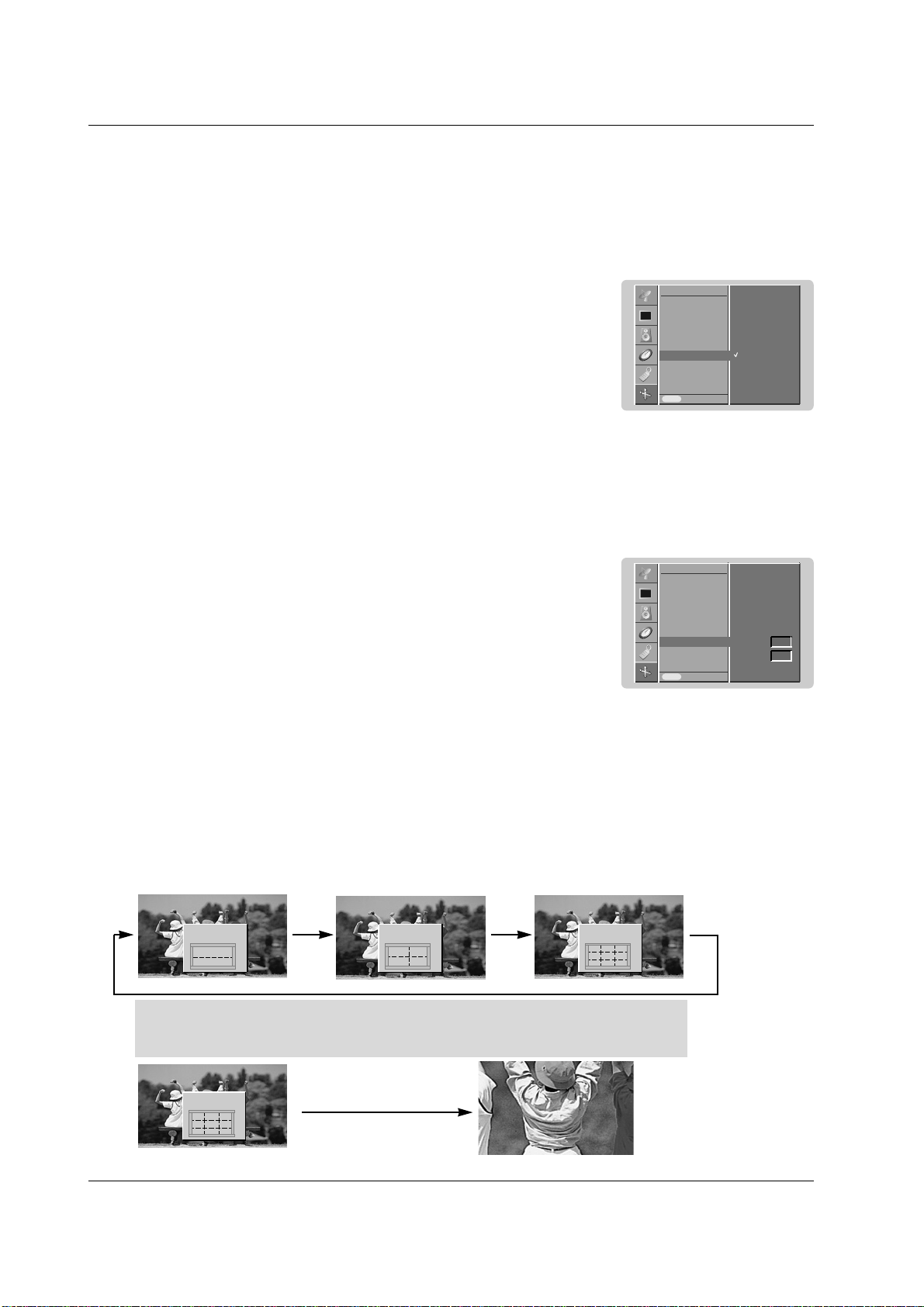
Split Zoom
- This is the function to enlarge the screen with regular ration.
- It’s available to use this function in every input source.
- It’s not available to use this function in Rotate mode.
- With 2-SPLIT ZOOM, you can only move the screen into upside or downside.
- If a screen is enlarged, a screen can move without selecting a section of screen.
1. Press the SPLIT ZOOM button.
• Each press of SPLIT ZOOM button changes the screen display as shown below.
In case of 9-Split Zoom:
Press the number button to select the section you want to enlarge.
If you choose No.5, the 5 section is enlarged and also can move the enlarged screen with
using the
DD
/
EE
or
FF
/
GG
button.
In case of choosing the No.5
The 5 section is changed to a full screen.
2-Split zoom
1
4
DD
EE
4-Split zoom
1 2
4 5
9-Split zoom
DD
FF GG
EE
DD
FF GG
EE
1 2 3
4 5 6
7 8 9
9-Split zoom
DD
FF GG
EE
1 2 3
4 5 6
7 8 9
Screen Menu Options
Screen Menu Options
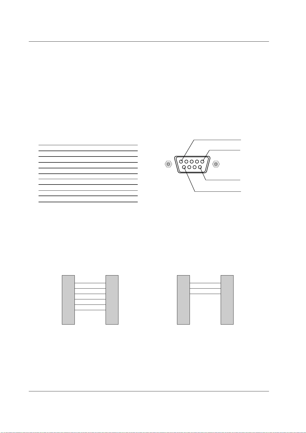
Owner’s Manual 29
Miscellaneous
No. Pin name
1 No connection
2 RXD (Receive data)
3 TXD (Transmit data)
4 DTR (DTE side ready)
5 GND
6 DSR (DCE side ready)
7 RTS (Ready to send)
8 CTS (Clear to send)
9 No Connection
1
5
6
9
2
3
5
4
6
7
8
RXD
TXD
GND
DTR
DSR
RTS
CTS
TXD
RXD
GND
DSR
DTR
CTS
RTS
PC
7-wire configuration
(Standard RS-232C cable)
D-Sub 9
3
2
5
6
4
8
7
PDP
D-Sub 9
2
3
5
4
6
7
8
RXD
TXD
GND
DTR
DSR
RTS
CTS
TXD
RXD
GND
DTR
DSR
RTS
CTS
PC
3-wire configuration
(Not standard)
D-Sub 9
3
2
5
4
6
7
8
PDP
D-Sub 9
External Control Device Setup
External Control Device Setup
- Connect the RS-232C input jack to an external control device (such as a computer or an A/V control system)
and control the set’s functions externally.
How to connect external control equipment
• Connect the serial port of the control device to the RS-232C jack on the set back panel.
• RS-232C connection cables are not supplied with the set.
• The set remote control and front panel controls (except main power) will not be functional if the set is controlled by a PC
computer or other external device.
Type of connector; D-Sub 9-pin male
RS-232C configurations
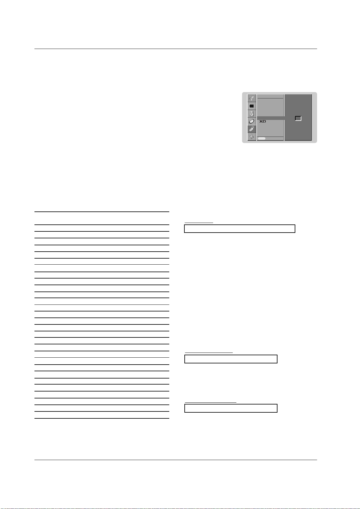
30 PLASMA MONITOR
Miscellaneous
Set ID
- Use this function to specify a set ID number.
- Refer to ‘Real Data Mapping 1’. See page 34.
1. Press the MENU button and then use the
DD
/
EE
button to select the SPECIAL menu.
2. Press the
GG
button and then use
DD
/
EE
button to select Set ID.
3. Press the
GG
button and then use F / G button to adjust Set ID to choose the desired
monitor ID number.
• The adjustment range of Set ID is 1 ~ 99.
4.
Repeatedly press the MENU button to return to normal viewing.
• Baud rate : 9600 bps (UART)
• Data length : 8 bits
• Parity : None
* Use a crossed (reverse) cable.
• Stop bit : 1 bit
• Communication code : ASCII code
Communication Parameters
Input
Language
Child lock
ISM Method
Low power
Set ID
Demo
OSD Rotate
Prev.
SPECIAL
Menu
Set ID
GG
1
T
ransmission
*
[Command 1] : First command to control PDP set.
(j, k, m or x)
*
[Command 2] : Second command to control PDP set.
*
[Set ID] : You can adjust the set ID to choose
desired monitor ID number in special
menu.
Adjustment range is 1 ~ 99.
When selecting Set ID ‘0’, every
connected PDP set is controlled.
Set ID is indicated as decimal (1~99) on
menu and as Hexa decimal (0x0~0x63)
on transmission/receiving protocol.
*
[DATA] : To transmit command data.
Transmit ‘FF’ data to read status of
command.
*
[Cr] : Carriage Return
ASCII code ‘0x0D’
*
[ ] : ASCII code ‘space (0x20)’
[Command1][Command2][ ][Set ID][ ][Data][Cr]
OK Acknowledgement
* The set transmits ACK (acknowledgement) based on this
format when receiving normal data. At this time, if the data
is data read mode, it indicates present status data. If the
data is data write mode, it returns the data of the PC com-
puter.
[Command2][ ][Set ID][ ][OK][Data][x]
Error Acknowledgement
* The set transmits ACK (acknowledgement) based on this
format when receiving abnormal data from
non-viable functions or communication errors.
[Command2][ ][Set ID][ ][NG][Data][x]
Transmission / Receiving Protocol
Command Reference List
*
When setting the 22 ~ 29, a menu doesn’t display on screen.
Data 1: Illegal Code
2: not support function
3: Wait more time
01. Power k a 0 ~ 1
02. Input Select k b Refer to p. 31
03. Aspect Ratio k c Refer to p. 31
04. Screen Mute k d 0 ~ 1
05. Volume Mute k e 0 ~ 1
06. Volume Control k f 0 ~ 64
07. Contrast k g 0 ~ 64
08. Brightness k h 0 ~ 64
09. Colour k i 0 ~ 64
10. Tint k j 0 ~ 64
11. Sharpness k k 0 ~ 64
12. OSD Select k l 0 ~ 1
13.
Remote control lock mode
k m 0 ~ 1
14. Split Zoom k p 0 ~ 99
15. Treble k r 0 ~ 64
16. Bass k s 0 ~ 64
17. Balance k t 0 ~ 64
18.
Colour Temperature (CSM)
k u 0 ~ 3
19. Red Adjustment k v 0 ~ 50
20. Green Adjustment k w 0 ~ 50
21. Blue Adjustment k $ 0 ~ 50
22. Abnormal Status k z 0 ~ a
23. ISM Method j p 0 ~ 3
24. Low Power j q 0 ~ 1
25. Orbiter Time Setting j r 1 ~ FE
26. Orbiter Pixel Setting j s 1 ~ 3
27. Auto Configure j u 1
28. Send IR Code m c Key code
29. Input select x b Refer to p. 34
COMMAND 1 COMMAND 2 DATA
(Hexadecimal)
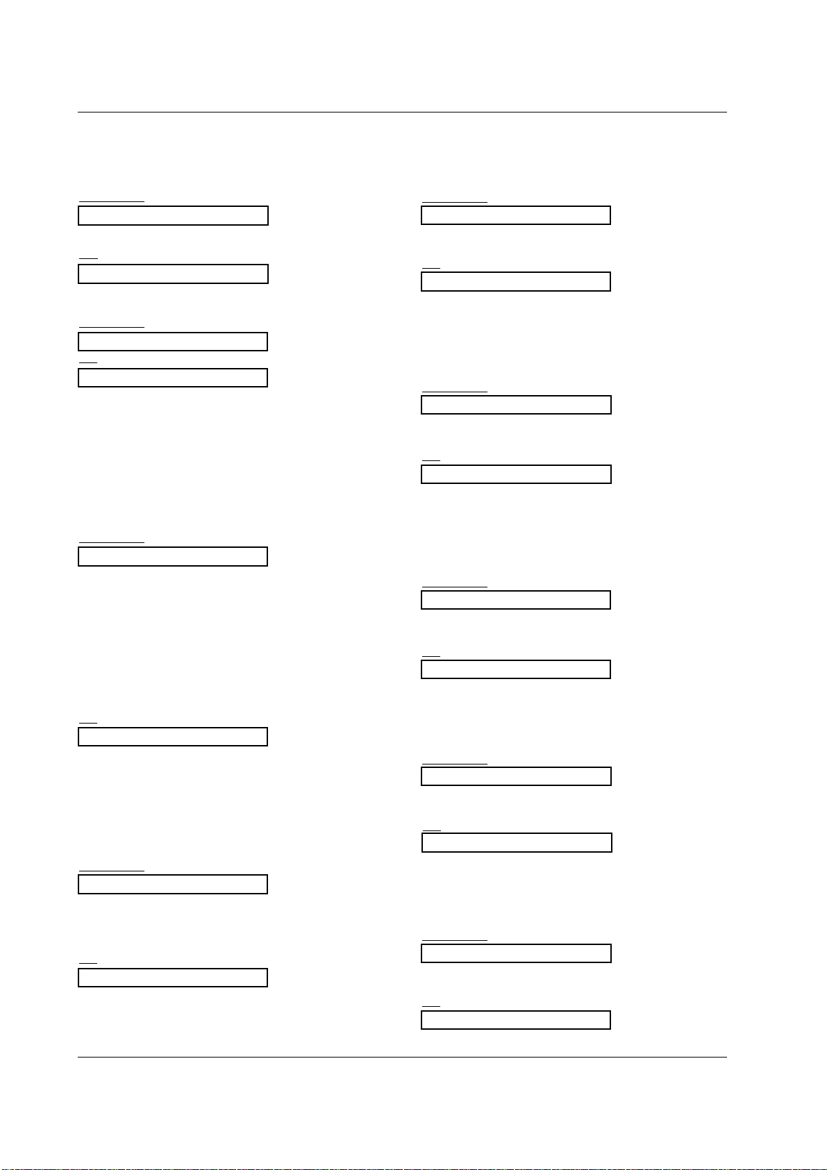
Owner’s Manual 31
Miscellaneous
05. Volume Mute (Command 2 : e)
G To control volume mute on/off.
You can also adjust mute using the MUTE button on
remote control.
T
ransmission
Data 1 : Volume mute on (Volume off)
0 : Volume mute off (Volume on)
[k][e][ ][Set ID][ ][Data][Cr]
Ack
[e][ ][Set ID][ ][OK][Data][x]
03. Aspect Ratio (Command 2 : c)
G To adjust the screen format. (Main picture format)
You can also adjust the screen format using the ARC
(Aspect Ratio Control) button on remote control or in the
SCREEN menu.
T
ransmission
Data 1 : Normal screen (4:3)
2 : Wide screen (16:9)
3 : Spectacle
4 : Full screen (Zoom)
6 : Original
7 : Wide screen (14:9)
8 : Full
[k][c][ ][Set ID][ ][Data][Cr]
Ack
* Using the PC input, you select either 16:9 or 4:3 screen
aspect ratio.
[c][ ][Set ID][ ][OK][Data][x]
04. Screen Mute (Command 2 : d)
G To select screen mute on/off.
Transmission
Data 0 : Screen mute off (Picture on)
1 : Screen mute on (Picture off)
[k][d][ ][Set ID][ ][Data][Cr]
Ack
[d][ ][Set ID][ ][OK][Data][x]
06. Volume Control (Command 2 : f)
G To adjust volume.
You can also adjust volume with the volume buttons
on remote control.
T
ransmission
Data Min : 0 ~ Max : 64
*
Refer to ‘Real data mapping 1’. See page 34.
[k][f][ ][Set ID][ ][Data][Cr]
Ack
[f][ ][Set ID][ ][OK][Data][x]
07. Contrast (Command 2 : g)
G To adjust screen contrast.
You can also adjust contrast in the PICTURE menu.
Transmission
Data Min : 0 ~ Max : 64
*
Refer to ‘Real data mapping 1’. See page 34.
[k][g][ ][Set ID][ ][Data][Cr]
Ack
[g][ ][Set ID][ ][OK][Data][x]
08. Brightness (Command 2 : h)
G To adjust screen brightness.
You can also adjust brightness in the PICTURE menu.
T
ransmission
Data Min : 0 ~ Max : 64
*
Refer to ‘Real data mapping 1’. See page 34.
[k][h][ ][Set ID][ ][Data][Cr]
Ack
[h][ ][Set ID][ ][OK][Data][x]
01. Power (Command 2 : a)
G To control Power On/Off of the set.
Transmission
Data 0 : Power Off 1 : Power On
[k][a][ ][Set ID][ ][Data][Cr]
Ack
[a][ ][Set ID][ ][OK][Data][x]
G To show Power On/Off.
Transmission
[k][a][ ][Set ID][ ][FF][Cr]
Ack
* In like manner, if other functions transmit ‘0xFF’ data
based on this format, Acknowledgement data feed back
presents status about each function.
[a][ ][Set ID][ ][OK][Data][x]
02. Input Select (Command 2 : b)
G To select input source for the set.
You can also select an input source using the INPUT
button on the set's remote control.
T
ransmission
Data 0 : RGB
1 : HDMI
2 : Component1
3 : Component2
4: AV
5 : S-Video
Data 0 : RGB
1 : HDMI
2 : Component
3:AV1
4: AV2
5 : S-Video2
6: AV3
[k][b][ ][Set ID][ ][Data][Cr]
Ack
- RCA Type -
- Scart Type -
[b][ ][Set ID][ ][OK][Data][x]
32 PLASMA MONITOR
Miscellaneous
17. Balance (Command 2 : t)
G To adjust balance.
You can also adjust balance in the SOUND menu.
T
ransmission
Data Min : 0 ~ Max : 64
*
Refer to ‘Real data mapping 1’. See page 34.
[k][t][ ][Set ID][ ][Data][Cr]
Ack
[t][ ][Set ID][ ][OK][Data][x]
16. Bass (Command 2 : s)
G To adjust bass.
You can also adjust bass in the SOUND menu.
T
ransmission
Data Min : 0 ~ Max : 64
*
Refer to ‘Real data mapping 1’. See page 34.
[k][s][ ][Set ID][ ][Data][Cr]
Ack
[s][ ][Set ID][ ][OK][Data][x]
15. Treble (Command 2 :r)
G To adjust treble.
You can also adjust treble in the SOUND menu.
T
ransmission
Data Min : 0 ~ Max : 64
*
Refer to ‘Real data mapping 1’. See page 34.
[k][r][ ][Set ID][ ][Data][Cr]
Ack
[r][ ][Set ID][ ][OK][Data][x]
13. Remote control lock mode (Command 2 : m)
G To lock the front panel controls on the set and remote
control.
Transmission
[k][m][ ][Set ID][ ][Data][Cr]
Ack
Data 0 : Lock off 1 : Lock on
* If you’re not using the remote control, use this mode.
When main power is on/off, external control lock is
released.
[m][ ][Set ID][ ][OK][Data][x]
12. OSD Select (Command 2 : l)
G To select OSD (On Screen Display) on/off when con-
trolling remotely.
T
ransmission
[k][l][ ][Set ID][ ][Data][Cr]
Ack
Data 0 : OSD off 1 : OSD on
[l][ ][Set ID][ ][OK][Data][x]
09. Colour (Command 2 : i)
G To adjust the screen colour.
You can also adjust colour in the PICTURE menu.
Transmission
Data Min : 0 ~ Max : 64
*
Refer to ‘Real data mapping 1’. See page 34.
[k][i][ ][Set ID][ ][Data][Cr]
Ack
[i][ ][Set ID][ ][OK][Data][x]
10. Tint (Command 2 : j) (option)
G To adjust the screen tint.
You can also adjust tint in the PICTURE menu.
T
ransmission
Data Red : 0 ~ Green : 64
*
Refer to ‘Real data mapping 1’. See page 34.
[k][j][ ][Set ID][ ][Data][Cr]
Ack
[j][ ][Set ID][ ][OK][Data][x]
G To adjust the screen sharpness.
You can also adjust sharpness in the PICTURE menu.
Transmission
11. Sharpness (Command 2 : k)
Data Min : 0 ~ Max : 64
*
Refer to ‘Real data mapping 1’. See page 34.
[k][k][ ][Set ID][ ][Data][Cr]
Ack
[k][ ][Set ID][ ][OK][Data][x]
14. Split Zoom (Command 2 : p)
G To operate split zoom function and select the split zoom
section number.
Transmission
[k][p][ ][Set ID][ ][Data][Cr]
Ack
Data Min: 0 ~ Max: 99
ex. Data 21: Selection 1 of 2 split zoom.
• Refer to ‘Real data mapping 2’.
[p][ ][Set ID][ ][OK][Data][x]
*
Real data mapping 2
0 : Reset split zoom
21: Selection 1 of 2 split zoom
24: Selection 4 of 2 split zoom
41: Selection 1 of 4 split zoom
42: Selection 2 of 4 split zoom
44: Selection 4 of 4 split zoom
45: Selection 5 of 4 split zoom
91: Selection 1 of 9 split zoom
99: Selection 9 of 9 split zoom
Owner’s Manual 33
Miscellaneous
19. Red Adjustment (Command 2 : v)
G To adjust red in colour temperature.
T
ransmission
Data Min : 0 ~ Max : 50
*
Refer to ‘Real data mapping 3’. See page 34.
[k][v][ ][Set ID][ ][Data][Cr]
Ack
[v][ ][Set ID][ ][OK][Data][x]
20. Green Adjustment (Command 2 : w)
G To adjust green in colour temperature.
Transmission
Data Min : 0 ~ Max : 50
*
Refer to ‘Real data mapping 3’. See page 34.
[k][w][ ][Set ID][ ][Data][Cr]
Ack
[w][ ][Set ID][ ][OK][Data][x]
21. Blue Adjustment (Command 2 : $)
G To adjust blue in colour temperature.
T
ransmission
Data Min : 0 ~ Max : 50
*
Refer to ‘Real data mapping 3’. See page 34.
[k][$][ ][Set ID][ ][Data][Cr]
Ack
[$][ ][Set ID][ ][OK][Data][x]
22. Abnormal State (Command 2 : z)
G To recognize an abnormal state.
T
ransmission
Data FF : Read
Data 0: Normal (Power on and signal exist)
1: No signal (Power on)
2: Turn the set off by remote control
3: Turn the set off by sleep time function
4: Turn the set off by RS-232C function
5: 5V down
6: AC down
7: Turn the set off by Fan Alarm function
8: Turn the set off by Off time function
9: Turn the set off by Auto sleep function
a: Turn the set off by AV board detect
* This function is “read only”.
[k][z][ ][Set ID][ ][FF][ ][Cr]
Ack
[z][ ][Set ID][ ][OK][Data][x]
23. ISM Method
(Command 1 : j, Command 2 : p)
G To control the ISM method. You can also adjust ISM
Method in SPECIAL menu.
T
ransmission
Data 0 : Normal Mode
1 : White Wash
2 : Orbiter
3 : Inversion
[j][p][ ][Set ID][ ][Data][Cr]
Ack
[p][ ][Set ID][ ][OK][Data][x]
24. Low Power
(Command 1 : j, Command 2 : q)
G To reduce the power consumption of the set. You can
also adjust Low Power in SPECIAL menu.
T
ransmission
Data 0 : Off
1 : On
[j][q][ ][Set ID][ ][Data][ ][Cr]
Ack
[q][ ][Set ID][ ][OK][Data][x]
25. Orbiter Time Setting
(Command 1 : j, Command 2 : r)
G To adjust orbiter operation time term.
Transmission
Data Min: 1 ~ Max: FE
*
Refer to ‘Real data mapping 1’.
[j][r][ ][Set ID][ ][Data][ ][Cr]
Ack
[r][ ][Set ID][ ][OK][Data][x]
18. Colour Temperature (Command 2 : u)
G To adjust colour temperature.
You can also adjust CSM in the PICTURE menu.
T
ransmission
Data 0: Cool 1: Normal 2: Warm 3: User
[k][u][ ][Set ID][ ][Data][Cr]
Ack
[u][ ][Set ID][ ][OK][Data][x]
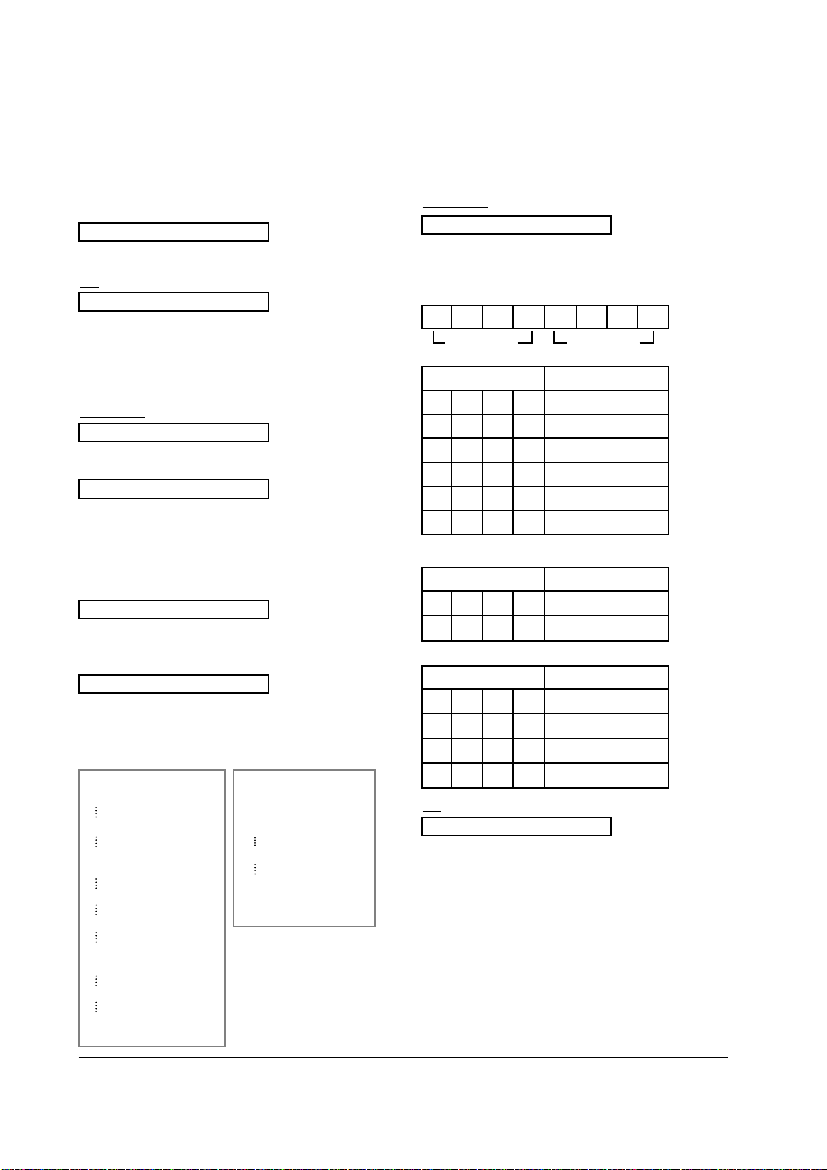
34 PLASMA MONITOR
Miscellaneous
28. Send IR Code
(Command 1 : m, Command 2 : c)
G To send IR remote key code.
Transmission
Data Key code - Refer to page 36~37.
[m][c][ ][Set ID][ ][Data][Cr]
Ack
[c][ ][Set ID][ ][OK][Data][x]
29. Input select (Command 1 : x, Command 2 : b)
G To select input source for the set.
T
ransmission
Data Structure
MSB LSB
0
[x][b][ ][Set ID][ ][Data][Cr]
Ack
[b][ ][Set ID][ ][OK][Data][x]
0 0 0 0 0 0 0
External Input Data
0 0 0 1 Analog
0010 AV
0 1 0 0 Component
0 1 0 1 RGB-DTV
0 1 1 0 RGB-PC
1 0 0 1 HDMI
External Input Input Number
27. Auto Configure
(Command 1 : j, Command 2 : u)
G To adjust picture position and minimize image shaking
automatically. It works only in RGB (PC) mode.
T
ransmission
Data 1: To set
[j][u][ ][Set ID][ ][Data][Cr]
Ack
[u][ ][Set ID][ ][OK][Data][x]
*
Real data mapping 3
0 : -40
1 : -39
2 : -38
28 : 0
4E : +38
4F : +39
50 : +40
Input Number Data
0 0 0 0 Input1
0 0 0 1 Input2
Input Number Data
0 0 0 0 Input1
0 0 0 1 Input2
0 0 1 0 Input3
0 0 1 1 Input4
- RCA Type -
- Scart Type -
26. Orbiter Pixel Setting
(Command 1 : j, Command 2 : s)
G To adjust pixel number in orbiter function.
Transmission
Data Min: 1 ~ Max: 3
*
Refer to ‘Real data mapping 1’.
[j][s][ ][Set ID][ ][Data][Cr]
Ack
[s][ ][Set ID][ ][OK][Data][x]
*
Real data mapping 1
0 : Step 0
A : Step 10 (Set ID 10)
F : Step 15 (Set ID 15)
10 : Step 16 (Set ID 16)
64 : Step 100
6E : Step 110
73 : Step 115
74 : Step 116
C7 : Step 199
FE : Step 254
FF : Step 255
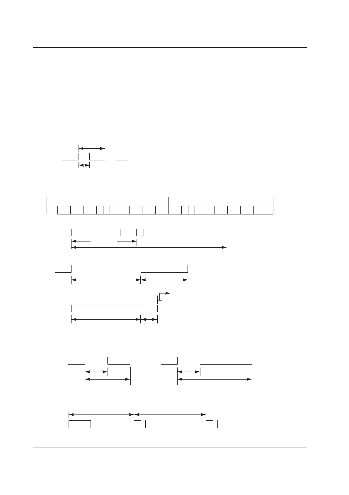
Owner’s Manual 35
Miscellaneous
G Connect your wired remote control to the Remote Control port on the set.
G Output waveform
Single pulse, modulated with 37.917KHz signal at 455KHz
G Configuration of frame
G Repeat code
G Lead code
• 1st frame
Low
custom code
Lead
code
High
custom code
Data code
Data code
TC
Tf
T1
C0
Carrier frequency
FCAR = 1/TC = fOSC/12
Duty ratio = T1/TC = 1/3
• Repeat frame
C1 C2 C3 C4 C5 C6 C7 C0 C1 C2 C3 C4 C5 C6 C7 D0 D1 D2 D3 D4 D5 D6 D7 D0 D1 D2 D3 D4 D5 D6 D7
Repeat code
9 ms 4.5 ms
0.55 ms
9 ms
2.25 ms
G Bit description
G Frame interval : Tf
The waveform is transmitted as long as a key is depressed.
• Bit “0”
Tf Tf
Tf=108ms @455KHz
0.56 ms 0.56 ms
1.12 ms
• Bit “1”
2.24 ms
IR Code (NEC Format)
IR Code (NEC Format)
How to connect
Remote Control IR Code (NEC Format)
36 PLASMA MONITOR
Miscellaneous
Code (Hexa) Function Note
UP (
D
)
DOWN (
E
)
VOL (
G)
VOL (F)
POWER
POWER ON
POWER OFF
MUTE
Number Key 0
Number Key 1
Number Key 2
Number Key 3
Number Key 4
Number Key 5
Number Key 6
Number Key 7
Number Key 8
Number Key 9
INPUT
MULTIMEDIA
COMPONENT1
COMPONENT2
HDMI
RGB
AV
S-VIDEO
I/II
SLEEP
MENU
OK( )
PSM
SSM
LIST
TEXT/
*
REVEAL
MODE
MIX
TIME
UPDATE
SIZE
HOLD
INDEX
ARC
ARC (4:3)
ARC (16:9)
ARC (Zoom)
00
01
02
03
08
C4
C5
09
10
11
12
13
14
15
16
17
18
19
0B
98
BF
D4
C6
D5
5A
D8
0A
0E
43
44
4D
52
53
20
2A
22
24
26
62
64
65
70
79
76
77
AF
R/C Button
R/C Button
R/C Button
R/C Button
R/C Button (Power On/Off)
Discrete IR Code (Only Power On)
Discrete IR Code (Only Power Off)
R/C Button
R/C Button
R/C Button
R/C Button
R/C Button
R/C Button
R/C Button
R/C Button
R/C Button
R/C Button
R/C Button
R/C Button
R/C Button
Discrete IR Code (Input COMPONENT1 Selection)
Discrete IR Code (Input COMPONENT2 Selection)
Discrete IR Code (Input HDMI Selection)
Discrete IR Code (Input RGB Selection)
Discrete IR Code (Input AV Selection)
Discrete IR Code (Input S-Video Selection)
R/C Button
R/C Button
R/C Button
R/C Button
R/C Button
R/C Button
R/C Button
R/C Button
R/C Button
R/C Button
R/C Button
R/C Button
R/C Button
R/C Button
R/C Button
R/C Button
R/C Button
Discrete IR Code (Only 4:3 mode)
Discrete IR Code (Only 16:9 mode)
Discrete IR Code (Only Zoom mode)
- RCA Type -
Owner’s Manual 37
Miscellaneous
Code (Hexa) Function Note
UP (
D
)
DOWN (
E
)
VOL (
G)
VOL (F)
POWER
POWER ON
POWER OFF
MUTE
Number Key 0
Number Key 1
Number Key 2
Number Key 3
Number Key 4
Number Key 5
Number Key 6
Number Key 7
Number Key 8
Number Key 9
INPUT
MULTIMEDIA
COMPONENT
HDMI
RGB
AV1
AV2
AV3
S-VIDEO2
I/II
SLEEP
MENU
OK( )
PSM
SSM
LIST
TEXT/
*
REVEAL
MODE
MIX
TIME
UPDATE
SIZE
HOLD
INDEX
ARC
ARC (4:3)
ARC (16:9)
ARC (Zoom)
00
01
02
03
08
C4
C5
09
10
11
12
13
14
15
16
17
18
19
0B
98
BF
C6
D5
5A
D0
D1
D3
0A
0E
43
44
4D
52
53
20
2A
22
24
26
62
64
65
70
79
76
77
AF
R/C Button
R/C Button
R/C Button
R/C Button
R/C Button (Power On/Off)
Discrete IR Code (Only Power On)
Discrete IR Code (Only Power Off)
R/C Button
R/C Button
R/C Button
R/C Button
R/C Button
R/C Button
R/C Button
R/C Button
R/C Button
R/C Button
R/C Button
R/C Button
R/C Button
Discrete IR Code (Input COMPONENT Selection)
Discrete IR Code (Input HDMI Selection)
Discrete IR Code (Input RGB Selection)
Discrete IR Code (Input AV1 Selection)
Discrete IR Code (Input AV2 Selection)
Discrete IR Code (Input AV3 Selection)
Discrete IR Code (Input S-Video2 Selection)
R/C Button
R/C Button
R/C Button
R/C Button
R/C Button
R/C Button
R/C Button
R/C Button
R/C Button
R/C Button
R/C Button
R/C Button
R/C Button
R/C Button
R/C Button
R/C Button
R/C Button
Discrete IR Code (Only 4:3 mode)
Discrete IR Code (Only 16:9 mode)
Discrete IR Code (Only Zoom mode)
- Scart Type -
38 PLASMA MONITOR
Miscellaneous
T
T
roubleshooting Checklist
roubleshooting Checklist
No output from one of the
speakers
• Adjust Balance in the SOUND menu. (Refer to p.22)
Unusual sound from
inside the set
• A change in ambient humidity or temperature may result in an unusual noise
at the time of switching off or on of the set and does not indicate a fault with
the set.
No picture &
No sound
• Check whether the set is turned on.
• Power cord inserted into wall outlet?
• Plug another product’s power cord into the wall outlet where the set’s power
cord was plugged in.
No or Poor colour
or Poor picture
• Select Colour in the PICTURE menu and press the VOLUME (G) button.
(Refer to p.20)
• Keep a certain distance between the set and the VCR.
• Activate any function to restore the brightness of the picture.
(If still picture is on the screen for more than 5 minutes, the screen gets dark.)
The remote control
doesn’t work
• Check to see if there is any object between the set and the remote control
causing obstruction.
• Check to see if the batteries are installed with the correct polarities.
(Refer to p.6)
• Check if the remote control handset is set up to correct mode.
• Install new batteries. (Refer to p.6)
Picture OK &
No sound
• Press the VOLUME (G) button.
• Sound muted? Press MUTE button.
Check whether the Speaker is “On” in the SOUND menu. (Refer to p. 22)
Picture appears slowly,
after switching on
• This is normal as the image is muted during the startup process of the set.
Please contact your service centre, if the picture has not appeared after five
minutes.
Horizontal/vertical bars
or picture shaking
• Check for local interference such as an electrical appliance or power tool.
Owner’s Manual 39
Miscellaneous
Product Specifications
Product Specifications
• The specifications shown above may be changed without notice for quality improvement.
MODEL
Width (inches / mm)
Height (inches / mm)
Depth (inches / mm)
Weight (pounds / kg)
Power requirement
Operating Temperature Range
Operating Humidity Range
50PM1M 50PM1MH
50PM1M-TA 50PM1MH-TA
50PM1M-ZA
49.3 / 1253
29.3 / 745
4 / 99.5
90.4 / 41
42PM1M 42PM1MH
42PM1M-TA 42PM1MH-TA
42PM1M-ZA
42 / 1066
25.6 / 650
3.9 / 97.5
66 / 30
AC100-240V, 50/60Hz
32 ~ 104°F (0 ~ 40°C)
Less than 80%
MODEL
Width (inches / mm)
Height (inches / mm)
Depth (inches / mm)
Weight (pounds / kg)
Power requirement
Operating Temperature Range
Operating Humidity Range
42PM3MV 42PM3MVH
42PM3MV-TA 42PM3MVH-TA
42PM3MV-ZA
41.4 / 1050
24.8 / 630
3.6 / 91.5
64 / 29
60PZ9M 60PZ9MH
60PZ9M-TA 60PZ9MH-TA
60PZ9M-ZA
56.9 / 1455
34.8 / 883
4.5 / 112
138.9 / 63
AC100-240V, 50/60Hz
32 ~ 104°F (0 ~ 40°C)
Less than 80%