User Manual Air Conditioner
INTRODUCTION
Thank you for choosing a De’Longhi product. Please take a few moments to read the instructions to a void risk sord amage to the appliance.
DESCRIPTION
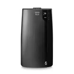
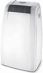
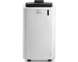
Description of the appliance
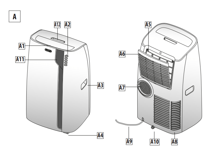
A1 Airoutletgrille
A2 Controlpanel
A3 Handles
A4 Wheels
A5 Filter
A6 Air intakegrille
A7 Airexhaust hose housing
A8 Air intakegrille
A9 Power supplycable
A10 Drainage hose with 2caps
A11 Remotecontrol signal receiver
A12 Remotecontrol compartment
Description of accessories
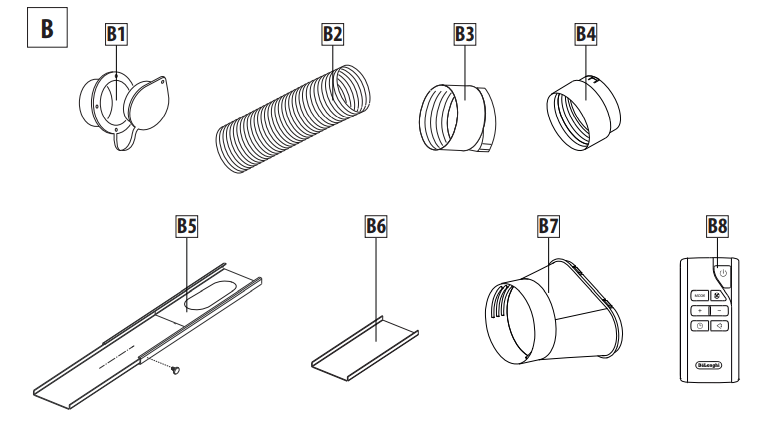
B1 Wall flange with cap
B2 Airexhaust hose
B3 Hoseadapter
B4 Wall mountingaccessory
B5 Window bracket
B6 Additional window bracket
B7 Window outlet
B8 Remotecontrol
Electrical connection
Before plugging the appliance into the outlet, checkthat:
- The outlet’s power supply corresponds to the value indicatedon the rating label on the back of the appliance;
- The outlet and electrical circuit are adequate for the appliance;
- The outlet is a 3-hole grounded outlet
 . If this is not the case,you must choose another outlet.Failure to follow these important safety instruction sabsolves the manufac-turer of all liability
If it becomes necessary, the power cable must be replaced by a qualified professional only
The instructions below will enable you to prepare your air con-ditioner for operation as efficiently as possible. Before use,make sure the air in take and outlet grilles are unobstructed.
USE
NOTE: This appliance is provided with an auto-evaporation feature for condensate removal during cooling and de-humidifing modes.
AIR CONDITIONING WITH INSTALLATION
For optimal results set-up your appliance in this way:
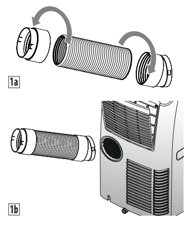
- Screw the hose adaptor B3 and B4 tothe hose’s end B2 as shown in figure1a.
- Fit the assembled air exhaust hose B2 in the housing at the backof the appliance. Insert itas shown in figure1b.
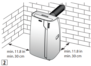
- Respect the distances given in figure2.
- Drill a hole ø 5,25 inches (134 mm) in an outside wall or through a window pane. Respect the dimensions and height of the holegiven in figure3and 4.
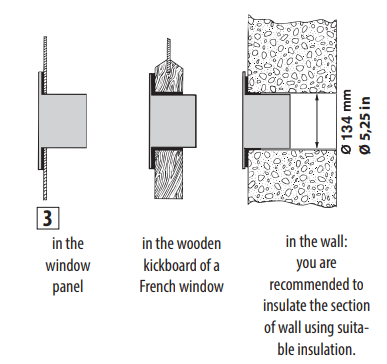
- Fit the wall flange B1 intothe hole.
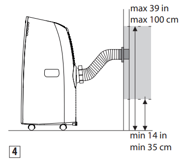
- Fit the hose with the wall mounting accessory B4 it intothe wall flange B1 as shown in fig.4.
- Fit the endof the hose B2 tothewall flange B1 asshown in fig.4.
- When the hose B2 is not connected, the drilled hole can be closed with the flangecap B1.
- When installing the air conditioner,you should leave a door slightly open little as 1/2“ (1 cm) to guarantee correct ventilation androom pressure.
- Keep the air hoses as short and freeof curves aspossibleto a void constrictions
NOTE: As special tools are required for installation, we suggest you have the appliance installed by specialized personnel.
AIR CONDITIONING WITHOUT INSTALLATION
You can also set-up in a double-hung window:
- Place the window bracket in the window sill, extend the bracket fully within the window frame, fix the bracket by using the pin then lower the window onto the bracket. (Should the window bracket be too large for the window. The plastic can be cut with a saw by a qualified professional.)
- Screw the hoseadaptor B3 tothe hose’send B2.
- Fit theairexhaust hose B2 in therelevant housinglocated on therear sideof theappliance. (fig.1).
- Screw the window outlet B7 to the other end of the exhaust hose.
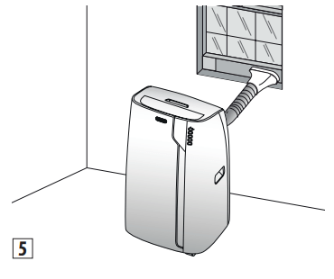
- Insert the window outlet B7 of the exhaust hose into the slotof the window bracket (fig.5).
Other set-up methods:
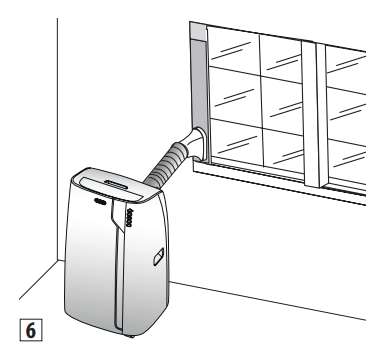
- Thanks tothe lockingpins, it’spossible touse the window bracket also for sliding windows. Position the hole of the bracket so to allow a correct installation of the exhaust hose (see figure6).
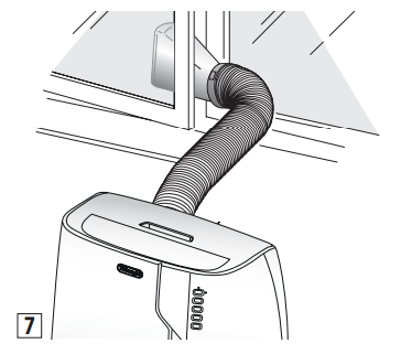
- If you have a casement window (figure 7) proceed as follows:
- Screw the hose a daptor B3 tothe hose’send B2.
- Fit the assembled air exhaust hose B2 in the relevant housing located on the rear side of the appliance. (fig. 1) then, apply the window outlet B7 to the air exhaust hose B2 and place it outside the window to exhaust the hot air.
CONTROL PANEL
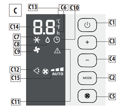
DESCRIPTION OF THE CONTROL PANEL (C)
C1 ON/STAND-BY (on/off)key
C2 Function selection key MODE (air conditioner, dehumidifier, fan)
C3 Temperature increase key
C4 Temperature decrease key
C5 Fan speed selection key (MIN/MED/MAX/AUTO)
C6 Hours indicator
C7 Air conditioner symbol
C8 Dehumidifier symbol
C9 Fan symbol
C10 Timer symbol
C11 Alarm symbol
C12 Swing symbol
C13 Selected temperature scale indicator
C14 Set temperature values ,programmed on/off time
C15 Fan speed indicator
OPERATING FROM THE CONTROL PANEL
TURNING THE APPLIANCE ON/OFF
Before plugging the appliance check the cap on back of the unit are correctly inserted on drainage hose A10
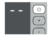
Insert theplugin the socket.Two dashes appear on the display indicating that the applianceis in stand-by.
Touch the  (C1) key toturn on the appliance. The flap A1 willopen after few seconds. When the appliance comes on, the last function set befor eit was shutoff isactivated.
NOTE: If start-up is not continued, after a few minutes the dis play lightdims in order to reduce energy consumption. To turn the appliance off, touch the key and then pull the plug.
NOTE: Never turn off the air conditioner by simply pulling the plug. Touch the key in order to put your air conditioner in stand-byand waitafew minutes before pulling the plug. In this manner, the appliance can perform the operating status checks.
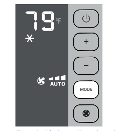
AIR CONDITIONING MODE

This is ideal for hot and humid weather when the room needs to beboth cooled and dehumidified.
To correctly set this mode:
- Touch the MODE key until the air conditioning symbol appears.The display will show the desired temperature.
- To change the temperature to be reached, touch the + (C3) keyor the
 (C4)key.
- Select the desiredfan speed by touching the key.
The speed savailable are:
 Minimum speed: when maximum silent operation is desired.
 Medium speed: when the noise level needs to be low but with a good comfort level
 Maximum speed: to reach the desired temperature as soon aspossible
 The appliance automatically chooses the best fan speed based on the temperature selected and the environmental conditions.
The most suitable temperatures during the summer range from 75 to 81°F. However, setting the temperature significantly lower than the outdoor temperature is not recommended
DEHUMIDIFYING MODE
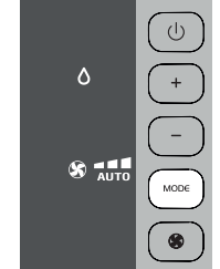
This is ideal for reducing humidity in the room (spring and autumn, damp rooms, rainy periods, etc. For this type of use, the appliancemustbesetupas forairconditionermode.That is, the air exhaust hose (B2) mustbe fitted to the appliance to allow the humidity tobe discharge doutside.
To correctly set this mode:
- Touch the MODE key until the dehumidifier symbol appears.
- The appliance auto matically chooses thebest fan speed.
FAN MODE
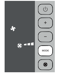
When using this mode, the air exhaust hose (B2) does not need tob eattached to the appliance.
To correctly set this mode:
• Touch the MODE key until the fan  symbol appears.
• Select the desired fan speed by touching the key  . The speeds available are:
 Minimum speed: when maximum silent operation is desired.
 Medium speed: when the noise level needs tobe low but with a good fan level.
 Maximum speed: for maximum fan power.
SELECT THE TEMPERATURE SCALE
The temperature can be display edin °Cor °F.
To change the temperature unit of measure touch both keys“+” and“-” for about 10 sec.
OPERATING FROM THE REMOTE CONTROL
USING THE REMOTE CONTROL
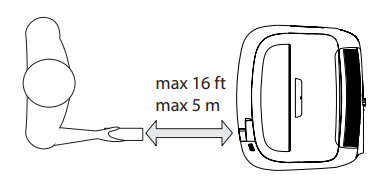
• Point the remote control at the receiver (A11) on the air conditioner. The remote control must be no more than 16 ft (5 metres) away from the appliance (without obstacles between the remote control and the receiver).
• The remote contro lmustbe handled with care. Do not drop it or exposeit todirect sunlightor sources of heat.
NOTE: The remote control can be safely storedin the appropriate compartment A12(see figure).
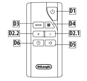
DESCRIPTION OF THE REMOTE CONTROL
D1) ON/STAND-BY button
D2.1)Temperatu redecrease /programmed operation button
D2.2)Temperatu reincrease/programmed operation button
D3) MODE function button
D4) Fan speedselection button
D5) Swing button (flapswing)
D6) Timerbutton
TURNING THE APPLIANCE ON
- Plugin to the outlet.
- Press the
 button (D1) (when turned on, the air conditioner start so perating in the same mode as when it was turned off) .
- To switch the appliance off, press button (D1) , then remove the plug.
NOTE: Never switch the appliance off by removing the plug. Always switch itoff by pushing on the button and waiting few minutes before removing the plug. Only in this way the appliance will perform the standard checkings.
SELECTING THE OPERATING MODES
The commands available on the remote control correspond to those on the appliance control panel (C). There fore, refer to the instructions in the previous chapters.
NOTE: The special functions D5-D6, are available from the remote control only.
SWING BUTTON
The SWING button (D5) moves the grille flap,evenly distributing the air into the room.
When the SWING button is pressed, the flap will begin to move forwards and back ward salter natively.
If pressed again, the flap will be locked intoits current position. When the button is next pressed, the flap will start to move forwards and back wards again.
NOTE: in order to avoid damaging the internal mechanisms, the flap must not be moved manually.
SETTING THE TIMER
The timer allows for the delayed start up or shut down of the appliance.This function will prevent wasting electricity by optimising the operating periods.
How to program delayed start up
- Plugin the appliance and set to standby.
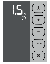
- Press the timer key (D6): the timer symbol (C10) and hours (C6) lightup.
- Use the + (D2.2)or - (D2.1) key to set the number of hours until the appliance should startup.
When the set time iselapsed, the appliance will start to operate in the same operating mode that was previously set.
Start up can be programmed at any time within the 24 hours that follow. A few seconds after the timer is set, the setting is acquired. The timer symbol stays lit and the display returns to standby.
To cancel the timer program, touch the timer key(D6) twice. The timer symbol (C10) willgooff.
How to program delayed shut down
- While the appliance is on in any operating mode, delayed shutdown can be programmed.
- Press the timer key(D6):The timer symbol (C10) and hours (C6) lightup.
- Use the + (D2.2)o- (D2.1) key to set the number of hours until the appliance will shutdown.
A few seconds after the timer is set, the settingis acquired, the display shows the operating mode and the timer symbol stays lit.
Once the set time iselapsed, the air conditioner goes into standby. To cancel the timer program, touch the timer key (D6) twice. The timer symbol (C10) willgooff.
INSERTING OR REPLACING THE BATTERIES
- Remove the cover on the rear of the remote control;
- Replace the old batteries with two new R03“AAA”1.5V batteries, inserting them correctly (see the instructions inside the battery compartment);
- Replace the cover.
If the remote control unit is replaced or discarded, the batteries must be removed and disposed of in accordance with current legislation as they are harmful to the environment. Do not mix old and new batteries.
Do not mix alkaline, standard (carbon-zinc) or rechargeable (nickel-cadmium) batteries. Do not dispose of batteries in fire. Batteries may explode or leak. If the remote control is not be used for a certain length of time, remove the batteries.
Note:
- This equipment has been tested and found to comply with the limits for a Class B digital device,pursuant to part 15 of the FCC Rules.These limits ar edesigned to provide reasonable protection against harmful interference in a residential installation.
- This equipment generates, uses and can radiate radio frequency energy and, if not installed and used in accordance with the instructions, may cause harmful interference to radio communications. However, there is no guarantee that interference will not occur in aparticular installation. If this equipment does cause harmful interference to radio or television reception, which can be determined by turning the equipment off andon, theuser is encouraged to try to correct the interference by one or more of the following measures:
- Reorient or relocate the receiving antenna.
- Increase the separation between the equipment and receiver.
- Connect the equipment in to an outleton acircuit different from that to which the receiver is connected.
- Consult the dealeror an experienced radio/TV technician for help
Changes or modifications not expressly approved by the party responsible for compliance could void the user’s authority to operate the equipment.
- This device complies with Part 15 of the FCC Rules. Operation is subject to the following two conditions: (1) this device may not cause harmful interference, and (2) this device must accept any interference received, including interference that may cause undesired operation.
- ThisClass B digital apparatus complies with Canadian ICES003.
SELF-DIAGNOSIS
The appliance has a self diagnosis system to identify a number of malfunctions.
Error messages are displayed on the appliance display.
... DO THE FOLLOWING
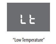
The appliance has a defrosting device that prevents exces siveice buildups.The appliance automatically starts operating again once the defrosting process is complete.
- IF THE FOLLOWING APPEARS ON THE DISPLAY...
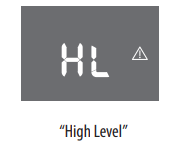
... DO THE FOLLOWING
Empty the inner water tray by following theinstructionsin the paragraph “END OF SEASON OPERATIONS”.
If the error occurs again, please contact our toll free customer service call center.
- IF THE FOLLOWING APPEARS ON THE DISPLAY...
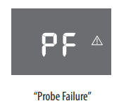
... DO THE FOLLOWING
If this appears, please contact our toll free customer service call center.
TIPS FOR CORRECT USE
To ensure optimal results from yourair conditioner, follow these recommendations:
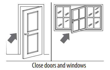
- close the windows and doors in the room to be air conditioned When installing the air conditioner semi-permanently, you should leave a door slightly open (as little as 0.39inch. (1cm)) to guarantee proper ventilation.
- Never use the appliancein very damp rooms (laundries for example).
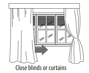
- Protect the room from direct exposure to the sun by partially closing curtains and/orblinds to make the appliance much more economical torun
- Never use the appliance outdoors.
- Make sure there are no heat sources in theroom;
- Make sure the air conditioner is standingon alevel surface.
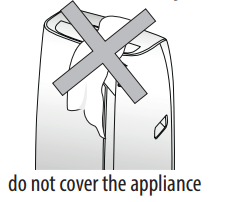
- Never rest objects of anykind on the air conditioner;
- Never obstruct the air intakeor outlet grilles;
CLEANING
Before cleaning or maintenance, turn the appliance off by touching the  button, then unplug from the outlet.
CLEANING THE CABINET
You should clean the appliance with a slightly damp cloth then dry with a dry cloth. For safety reasons, never wash theair conditioner with water.
Precautions
Never use petrol,alcoholor solvents to clean the appliance. Never spray insecticide liquids or similar.
CLEANING THE AIR FILTER OR SILVER-ION AIR FILTER (If fitted)
To maintain the efficiency of the air conditioner, it is recommended to clean thedust filter afte revery week of use.
The filter is located near the intake grille. Remove the grille to access the filter. To clean the filter, it will need to be extracted as shown in fig.8-9.
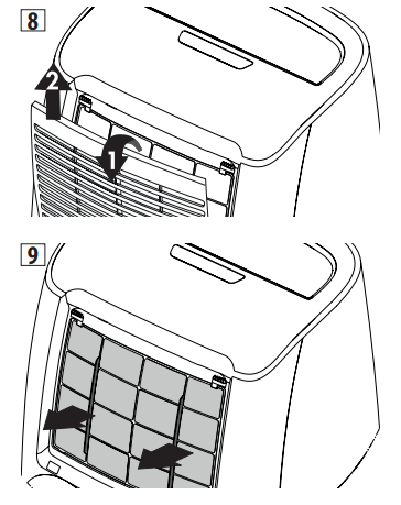
Use av acuum cleaner to remove any dust depositedon the filter. If it is very dirty,sub mergeit into warm water and rinseit several times.The water temperature must be kept below 104°F. After washingthe filter, allow it to dry.To replace,put the filter backin its housing. Ifpresent, thesilver-ion air filter not only retains powder particles ,but also performsan efficientan tibacte-rial action. In addition, it greatly reduces irritants such aspollen and spores.The filter is treated with small particles of silver (with dimensions equal to millionths of a millimetre) which are able to block the multiplication of bacteria and spores when in contact with them, and therefore encourage their destruction.
CHECKS AT THE START OF THE SEASON
Make sure the power cable and socket are in perfect condition and make sure the earthing system is efficient. Comply strictly with the installation standards.
END OF SEASON OPERATIONS
To completely drain the water from the internal circuit, remove the cap from the outside of the drainage hose, turningit counter clockwise.Then remove the internal cap(fig. 10). Drain the water completely into a basin.When it is completely drained, replace the caps, making sure they are completely closed.Clean the filter as indicated previously. The filter must be completely dry before reinserting it.
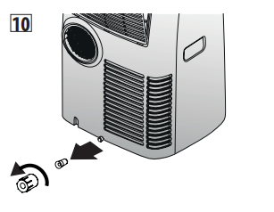
When the appliance is empty, replace the caps. Clean the filter and dry thoroughly before putting back.
TECHNICAL SPECIFICATIONS
Power supply voltage see rating label
Max.absor bed power during air conditioning “
Refrigerant “
Cooling capacity “
LIMIT CONDITIONS
Room temperature for
air conditioning 64 ÷ 95°F(18° ÷ 35°C)
Transport, filling, cleaning, recovery and disposal of refrigerant should be performed by a technical service centre appointed by the manufacturer only. The appliance should be disposed of by a specialist centre appointed by the manufacturer only.
TO AVOID DAMAGE TO THE UNIT:
NEVER TRANSPORT OR TURN THE APPLIANCE UPSIDE DOWN OR ON ITS SIDE. IF THIS OCCURS, WAIT 6 HOURS BEFORE TURNING
THE APPLIANCE ON,24 HOURSIS RECOMMENDED. After theunit hasbeen on its side,oil needs toreturn to the compressor to ensure proper function. Without allowing the unit this time(6-24 hours) the unit may function fo ronly a short time,and then the compressor wil lbreak down from lack of oil.
ELECTRICAL CONNECTION
This appliance is equipped with a 3 prong grounded plug. The plug must be connected into an outlet that is properly installed and grounded in the accordance with all local codes and ordinances. Do not modify the plug provided with the appliance. If it will not fit the outlet, have a proper outlet installed by a qualified electrician or relocate the unit to a properoutlet. If the household electrical supply does not meet the above specifications,or if you are not sure your home has an effective electrical ground, have aqualifiedel ectrician or your local electrical utility company checki tand correct any problems.
SAFETY PLUG
The appliance is fitted with a safety plug to protect the power cable. If power is cut off,unplug from the outlet and make sure the power cableisun damaged. If the cableis damaged, call the service center immediately. If power cuts off frequently and the power cableisun damaged, contact aqualified electrician.
OPERATION OF THE SAFETY PLUG
If the safety device incorporated in the plug trips and cuts off the power supply, check that the power cable and plug are not damaged. If the power cableisun damaged, to restore operation press the “RESET” button .To verify correcto peration of the plug, press the“TEST”button periodically and make sure the appliance disconnects. If this is not the case, contact the service center.To restore operation,press the “RESET” button.
TROUBLESHOOTING
Check the following points before calling the auth orised Technical Service Centrein your area
- The air conditioner does not turn on
- lt is not plugged in
- there is no power
- the internal protection device was triggere
- The air conditioner works for a short period of time
- the air exhaust hose is obstructed or bent
- correctly position the air exhaust hose, limiting the length and curves as much aspossible and avoiding jany ob structions
- an obstruction is impeding air exhaust outside
- identify and remove the obstacles that impede air exhaust outside
- The air conditioner runs but does not cool the room
- windows, doors, drapes open
- close the windows, doors and drapes, keeping in mind the “recommendations forproperuse”
- there is some heat source in the room (oven, hairdryer,etc.)
- the air exhaust hose is disconnected from the appliance
- attach the air exhaust hose to he housing on the back of the appliance (fig.1)
- dust filters clogged
- clean or replace the filters as previously described
- the technical characteristics of the appliance are not suitable for cooling the room whereit is located
- During operation there is an unpleasant odour in theroom
- dust filters clogged
- clean or replace the filters as previously described
- The air conditioner does not work for about 3 minutes from restart
- to protect the compressor there is an internal device that delays startup for about 3 minutes from restart
- wait;this time delay from restartis normal
- The display shows the
 symbol with one of the following messages: HL/PF
- the appliance has a self-diagnosis system that identifies some operating errors
- refer to the SELF-DIAGNOSIS chapter