ACC-S1-EH5C
www.lge.co.kr
P/No.: MFL69532005 (1605-REV00)
Printed in Korea
*MFL69532005*
사용설명서를 읽고 난 후 사용하는 사람이 언제라도 볼 수 있는 장소에
보관하세요.
사용설명서
실린더 스탠드 키트
2
ENG
한국어
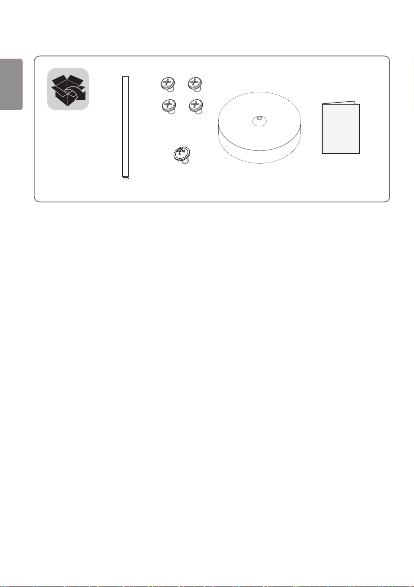
(M3 x L4.5)
(M3 x L5.5)
3
ENG
한국어
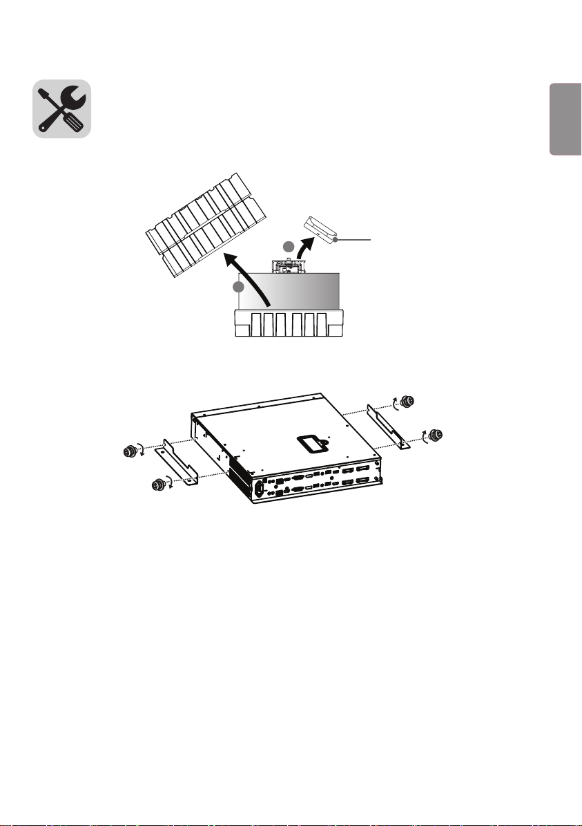
1 상자를 열고 위에 있는 포장 및 T-con 박스를 순서대로 제거합니다.
1
2
T-con 박스
2 마운팅 브래킷을 나사(M4 x L8) 4개로 사이니지 박스에 조립하여 설치합니다.
4
ENG
한국어
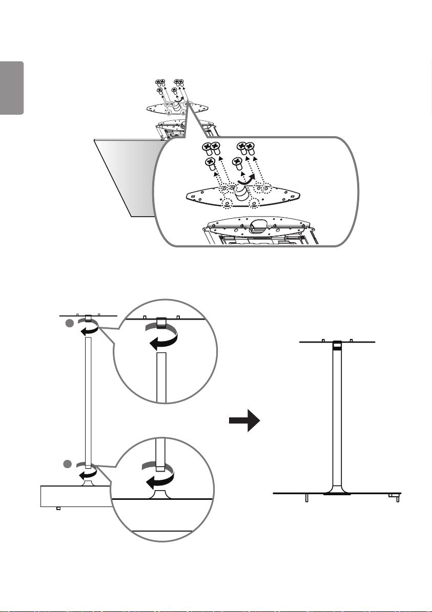
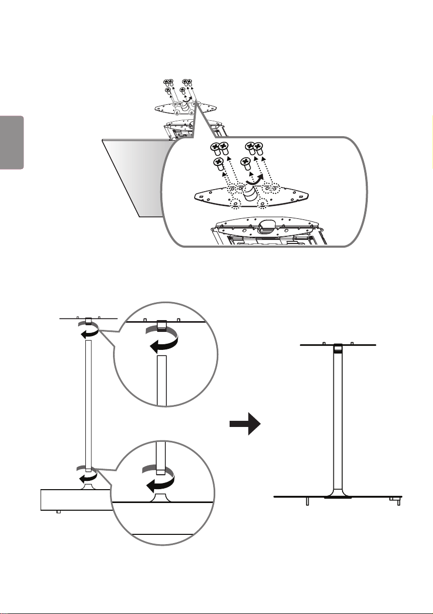
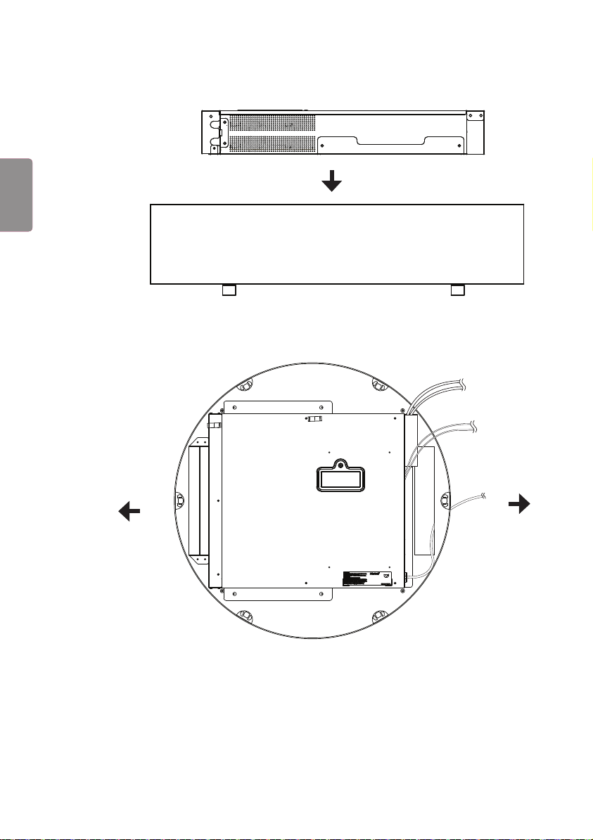
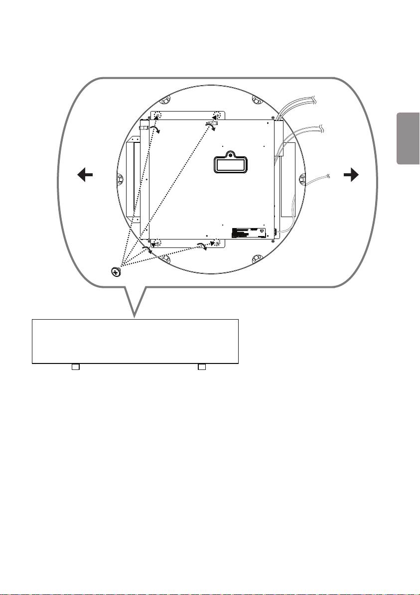
3 나사 6개를 풀어 세트의 프레임을 분리합니다.
4 Cylinder Stand Top에 파이프를 조립하고, 파이프에 프레임을 조립합니다. 그리고 파이프를 잡고 Cylinder Stand
Top을 개봉합니다.
2
1
5
ENG
한국어
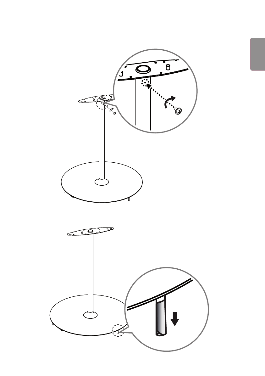
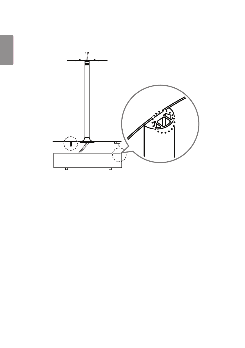
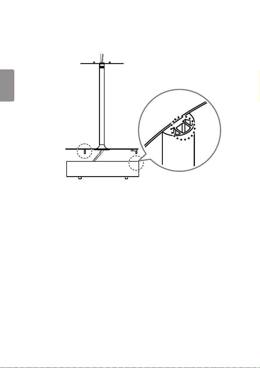
5 파이프 상단에 고정용 나사 홀에 나사(M3 x L5.5)를 체결하여 파이프와 프레임을 고정시킵니다.
6 Cylinder Stand Top 바닥면에 위치한 기둥 3개를 감싸고 있는 보호 테이프 3개를 모두 제거합니다.
6
ENG
한국어
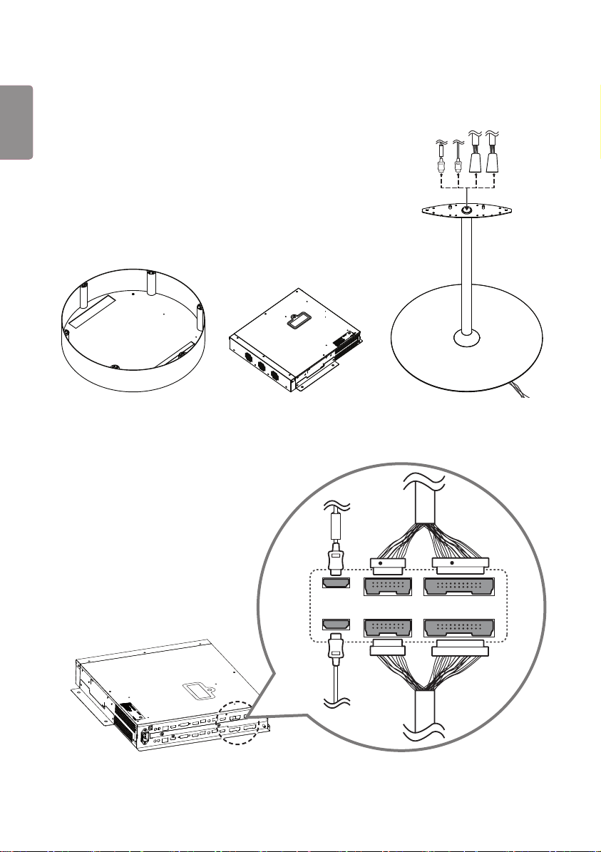
7 Cylinder Stand Top, 사이니지 박스와 Stand Bottom을 바닥에 나란히 정렬한 후 16/22핀 케이블과 HDMI
케이블을 상측 프레임 홀에서부터 아래 수직방향으로 삽입하여 통과시킵니다.
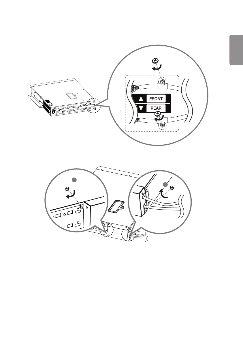
FRONT
8 사이니지 박스에 파이프를 통과시킨 케이블을 연결합니다. 이때 Front 케이블을 위에, Rear 케이블은 아래에
체결합니다. 16/22 pin 케이블의 경우 붉은색 표시가 있는 케이블을 위에 체결합니다.
16
16
22
22
FRONT
R
R
7
ENG
한국어
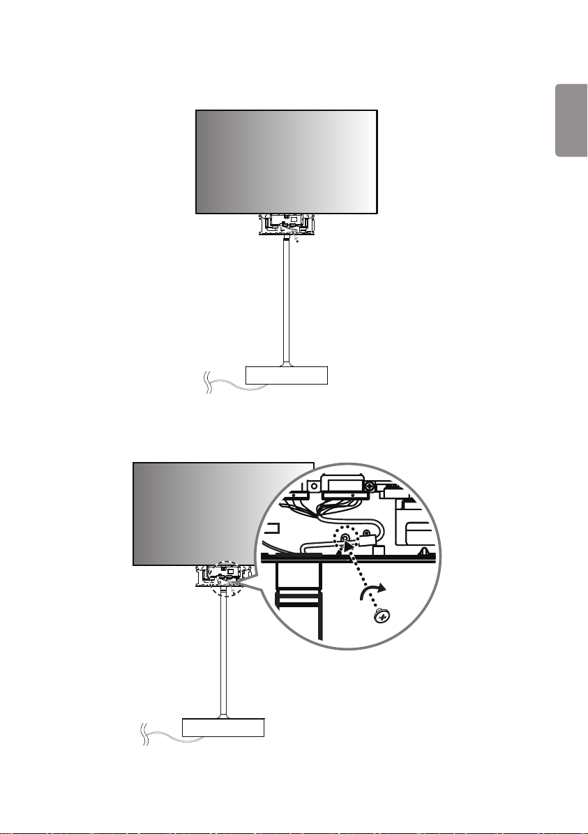
9 16/22 pin 케이블을 나사(M3 x L4.5) 2개로 각각 체결합니다.
22
16
22
16
10
잭커버의 홈을 케이블에 맞춰 덮고 나사(M3 x L4.5) 2개로 체결합니다.
1
2
8
ENG
한국어
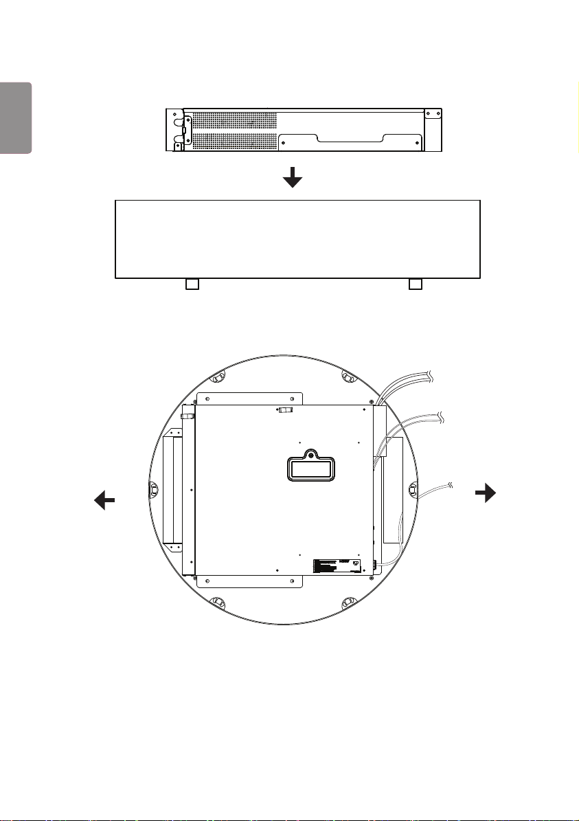
11
사이니지 박스를 스탠드 베이스에 집어 넣습니다.
12
전원 케이블을 스탠드 Connector 방향쪽 구멍으로 바닥에서 스탠드 안쪽으로 집어넣은 후 사이니지 박스에
체결합니다.
Fan 방향
Connector
방향
9
ENG
한국어
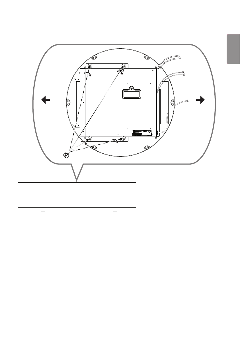
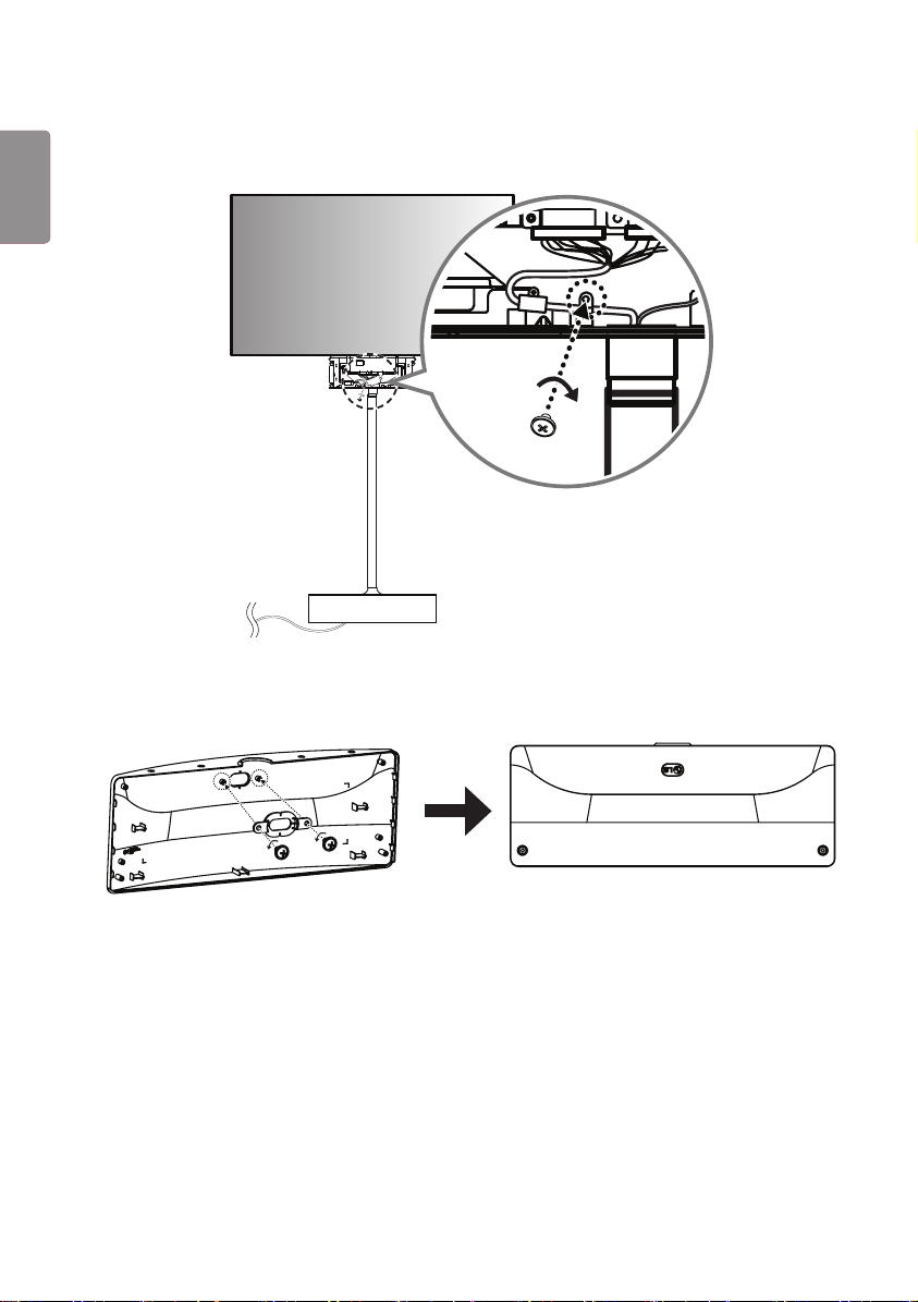
13
스탠드베이스에 케이블이 체결된 사이니지 박스를 설치하고, 나사(M3 x L4.5) 4개를 이용하여 고정합니다.
Connector
방향
Fan 방향
10
ENG
한국어
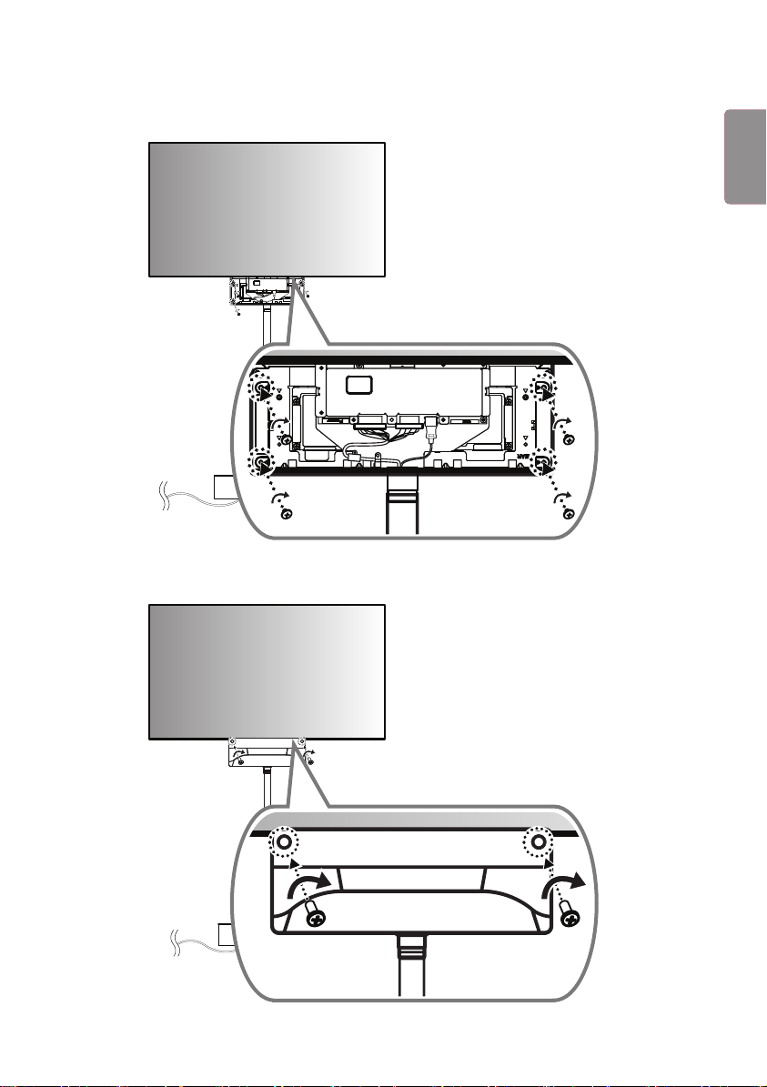
14
Cylinder Stand Top을 다시 Bottom Stand 위에 꽂아서 설치합니다. 이때 Stand Top 바닥의 돌출된 기둥 3개를
Stand의 가장자리에 위치한 구멍에 꽂아서 삽입합니다.
11
ENG
한국어
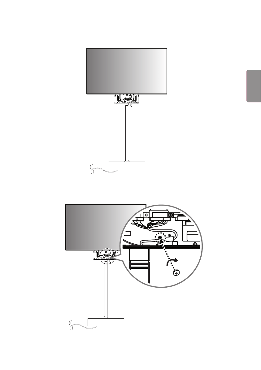
15
통과된 16/22핀 케이블과 HDMI 케이블을 Front/Rear로 구분한 뒤, 세트를 들어 프레임에 세트를 조립합니다.
22
FRONT
16
RR
16
FRONT 라벨이 붙은 HDMI 케이블을 Front 면에 연결합니다. 붉은색 표시가 없는 16/22 pin 케이블에 케이블
홀더를 끼우고 나사(M3 x L4.5)를 이용해 조립한 후 연결합니다.
22
FRONT
16
RR
22
FRONT
16
RR
12
ENG
한국어
17
FRONT 라벨이 없는 HDMI 케이블을 Rear 면에 연결합니다. 붉은색 표시가 있는 16/22 pin 케이블에 케이블
홀더를 끼우고 나사(M3 x L4.5)를 이용해 조립한 후 연결합니다.
16
22
16
22
18
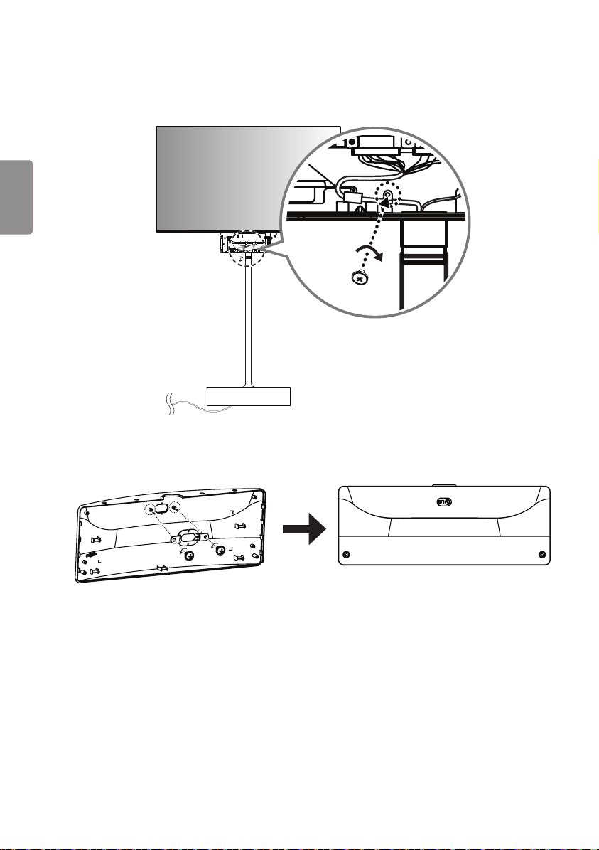
나사 2개를 분리하여 LG 로고 방향을 변경하여 재조립합니다.
13
ENG
한국어
19
T-con 박스의 IR 수신부가 있는 면을 Front 면에 덮고, 반대쪽에서 나사(Φ3 x L6) 4개로 체결합니다
16
22
16
22
20
나머지 T-con 커버를 rear 면에 덮고, 나사(Φ3 x L10) 2개로 체결합니다.
14
ENG
한국어
21
T-con 커버 하단에 나사(M4 x L8) 6개를 체결합니다.
15
ENG
한국어
스탠드 바닥면으로 나온 파워케이블을 전원코드에 연결합니다.


ACC-S1-EH5C
Please read this manual carefully before operating your set and retain it
for future reference.
OWNER’S MANUAL
Cylinder Stand kit
www.lg.com
2
ENG
ENGLISH
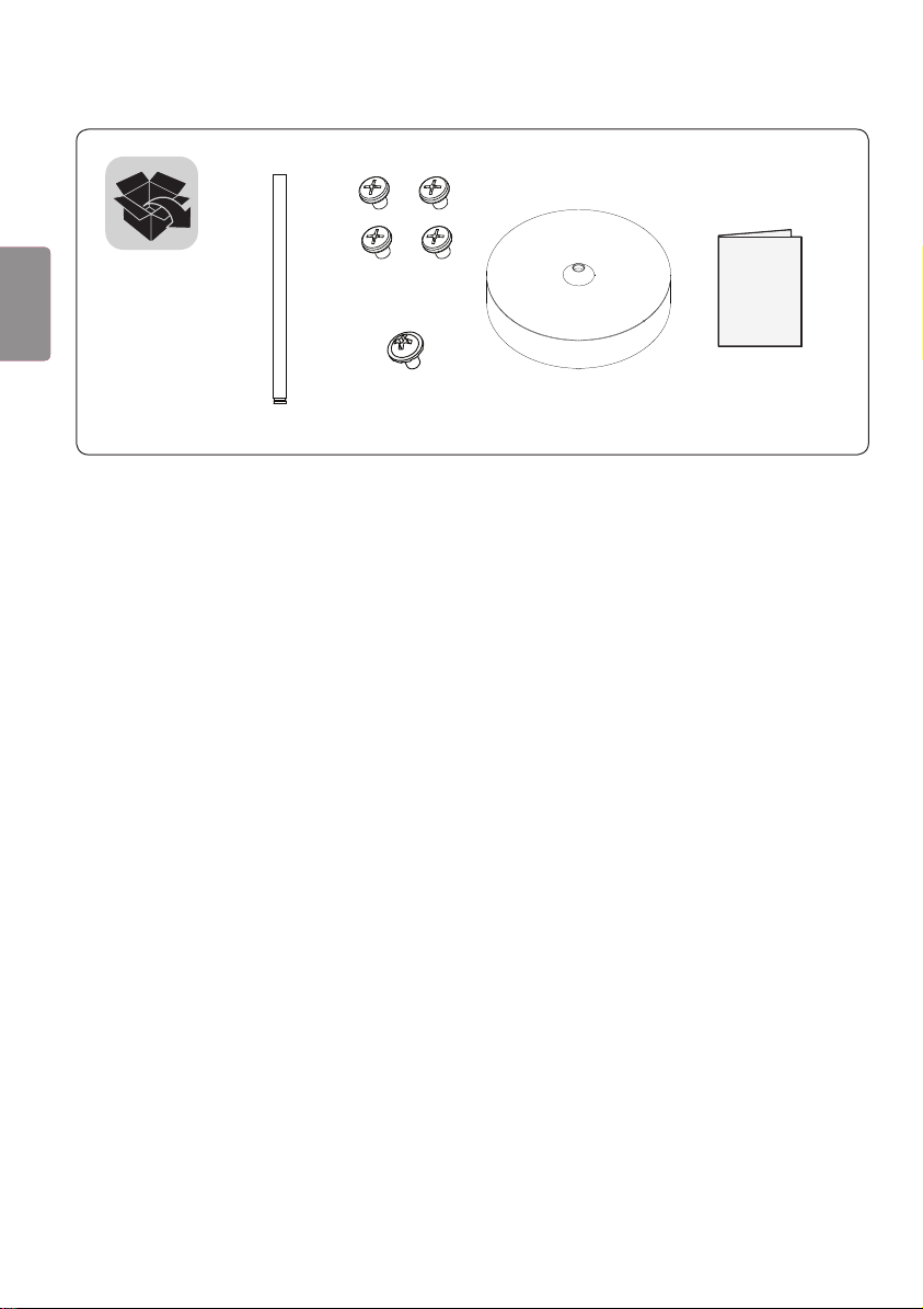
(M3 x L4.5)
(M3 x L5.5)
3
ENG
ENGLISH
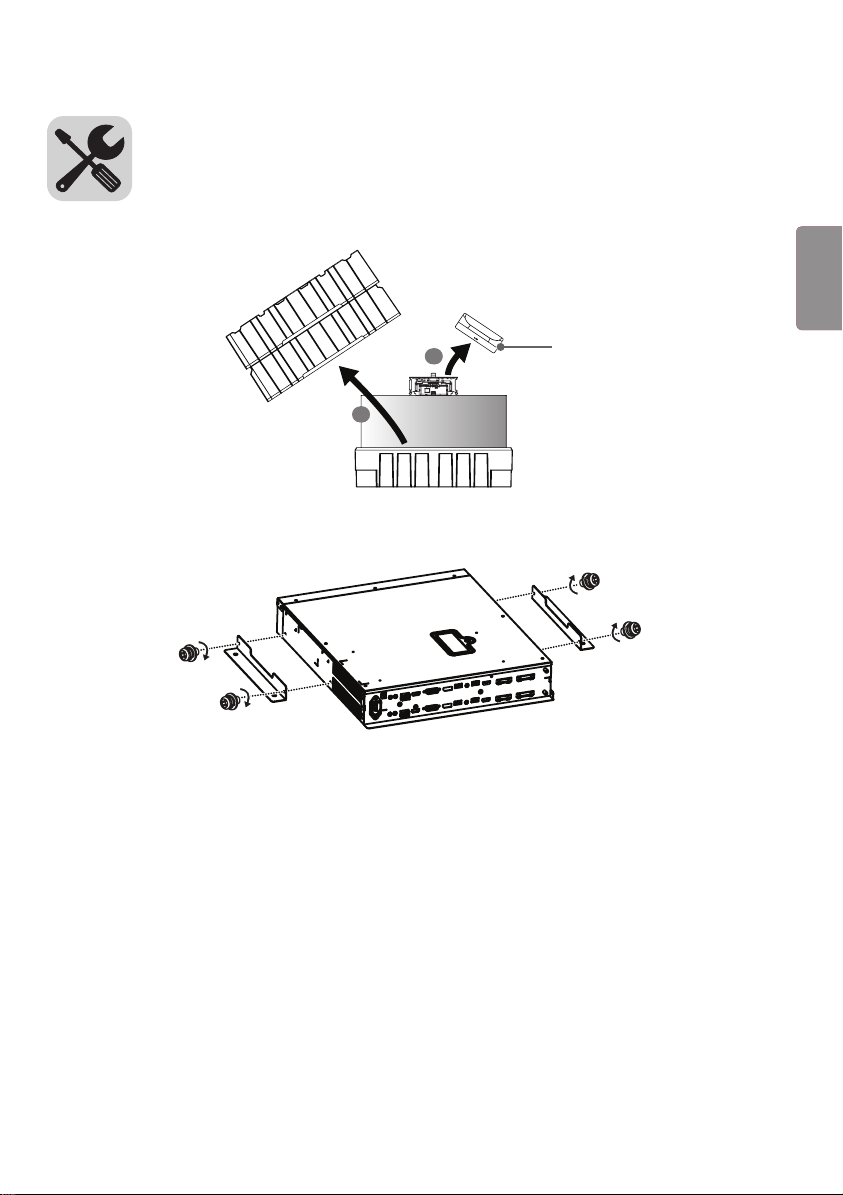
1 Open the product box and remove the packaging materials and the T-con box in the order they appear.
1
2
T-con box
2 Attach the mounting brackets to the Signage box using four screws (M4 x L8).
4
ENG
ENGLISH
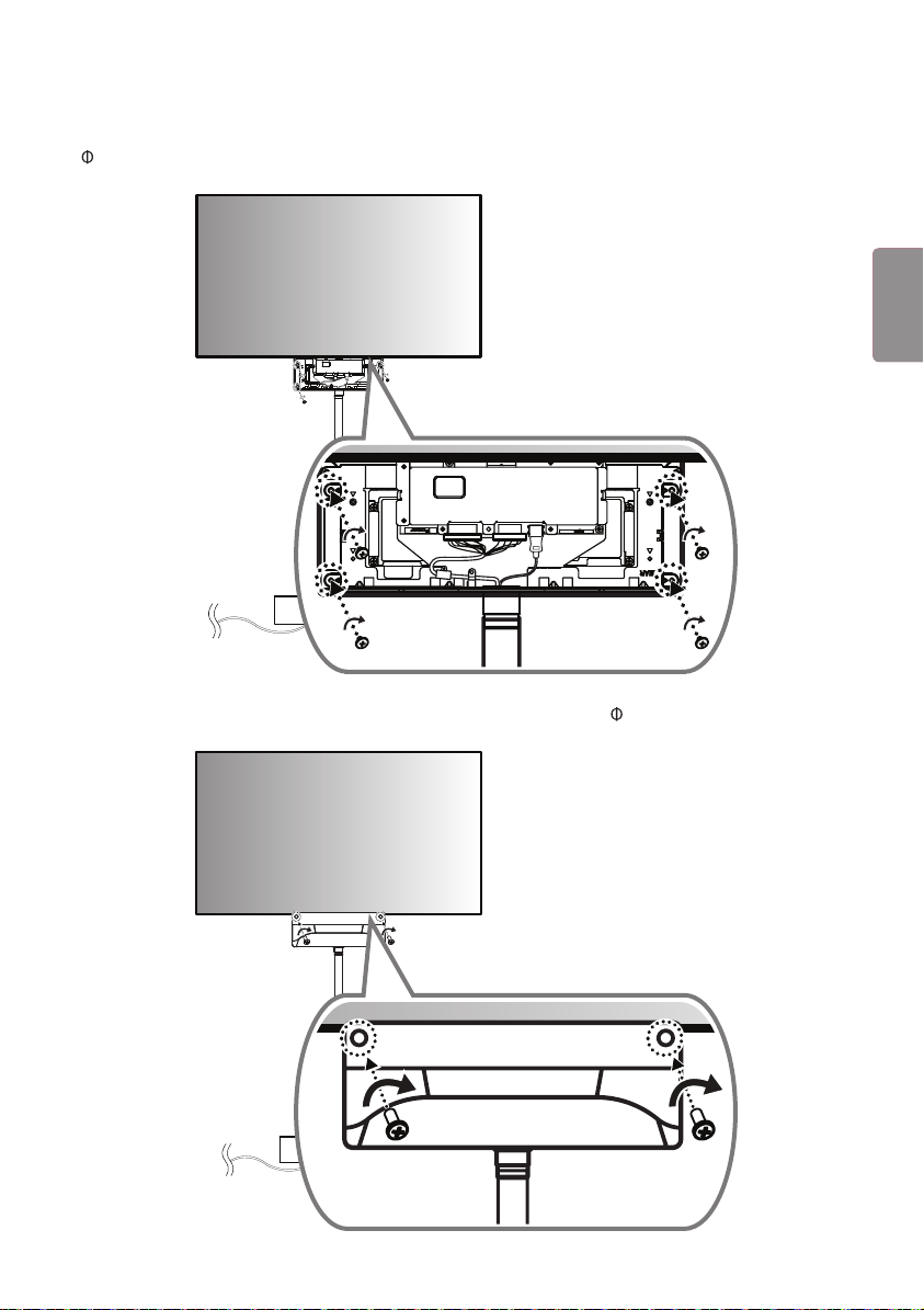
3 Loosen the six screws and remove the frame from the set.
4 Affix the pipe to the Cylinder Stand Top and the Top body to the pipe. Hold the pipe and pull up to open the Cylinder
Stand Top.
2
1
5
ENG
ENGLISH
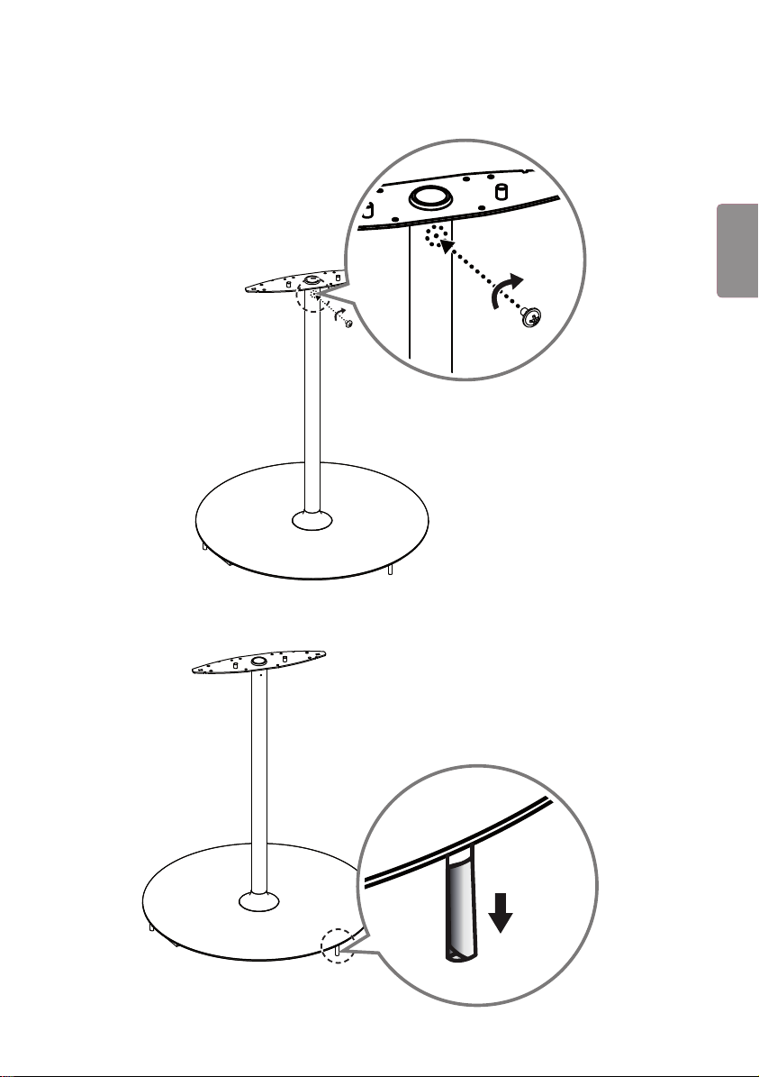
5 Attach the pipe to the frame by fastening a screw (M3 x L5.5) in the screw hole on the top of the pipe.
6 Remove the protective film on each of the three columns protruding from the bottom of the Cylinder Stand Top.
6
ENG
ENGLISH
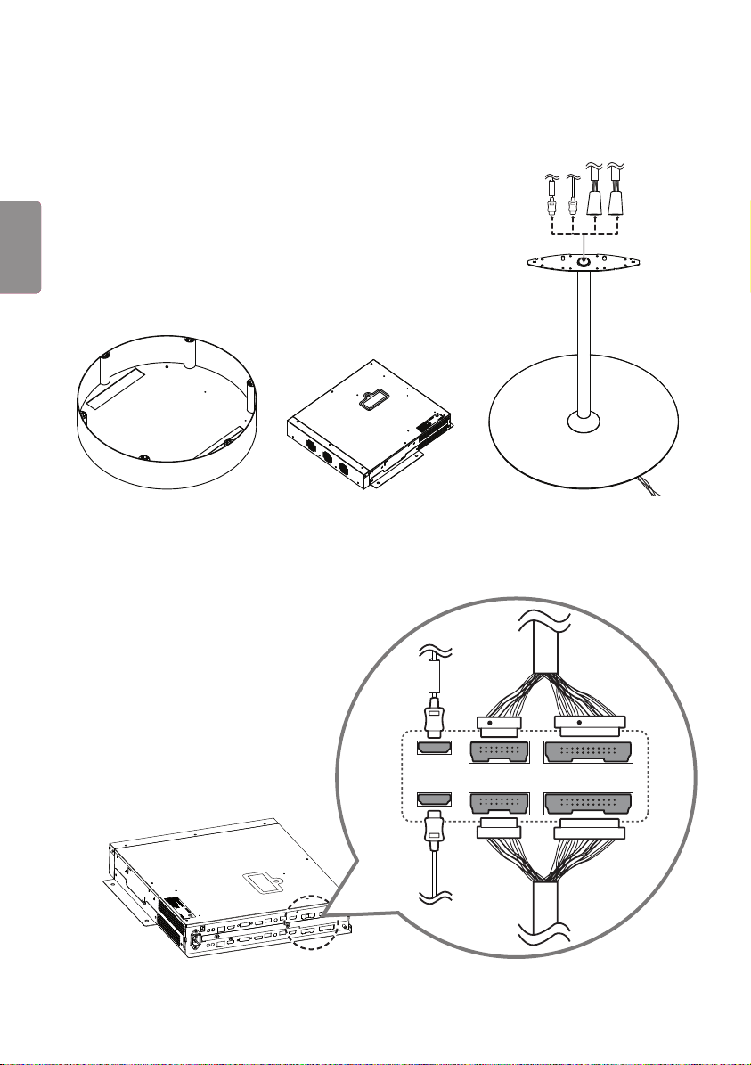
7 Line up the Cylinder Stand Top, Signage box, and Stand Bottom on the floor. Insert the 16/22 pin cable and HDMI
cable into the hole in the top body and pass the cables downward through the hole.
FRONT
8 Connect the cables passed through the pipe to the Signage box. The Front cable must be connected to the upper
part and the Rear cable must be connected to the lower part. The 16/22 pin cable with the red mark must be
connected to the upper part.
16
16
22
22
FRONT
R
R
7
ENG
ENGLISH
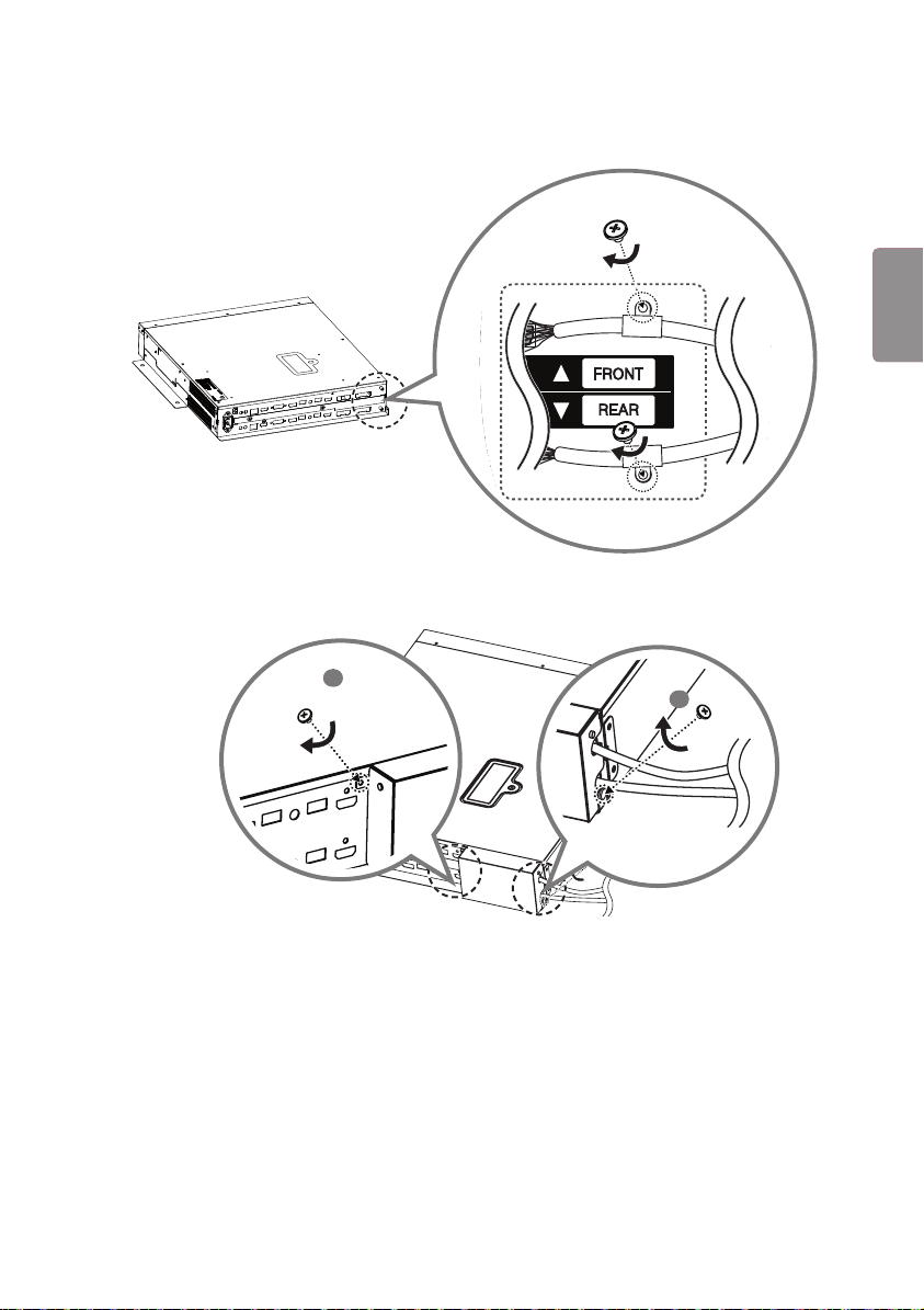
9 Attach the 16/22 pin cables using the 2 screws (M3 x L4.5).
22
16
22
16
10
Position the jack cover to fit the cables to the cut spaces and then attach it using the 2 screws (M3 x L4.5).
1
2
8
ENG
ENGLISH
11
Place the Signage box inside the stand base.
12
Pass the power cable through the hole in the bottom near the stand connector and into the inside of the stand, and
then attach the cable to the Signage box.
Fan direction
Connector
direction
9
ENG
ENGLISH
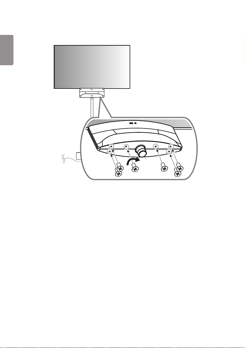
13
Install the Signage box with the attached cables onto the stand base and attach it using four screws (M3 x L4.5).
Connector
direction
Fan direction
10
ENG
ENGLISH
14
Install the Cylinder Stand Top onto the top of the Bottom Stand. The three columns protruding from the bottom of
the Stand Top should be inserted into the holes near the edges of the Stand.
11
ENG
ENGLISH
15
Identify the Front and Rear HDMI cables and 16/22 pin cables, then pick up the set and attach it to the frame.
22
FRONT
16
RR
16
Connect the HDMI cable with the label marked ‘FRONT’ to the front side. Insert the 16/22 pin cable without the
red mark into the cable holder and attach it using a screw (M3 x L4.5).
22
FRONT
16
RR
22
FRONT
16
RR
12
ENG
ENGLISH
17
Connect the HDMI cable without the label marked ‘FRONT’ to the rear side. Insert the 16/22 pin cable with the red
mark into the cable holder and attach it using a screw (M3 x L4.5).
16
22
16
22
18
Remove the two screws, change the direction of the LG logo, and then reassemble.
13
ENG
ENGLISH
19
Cover the front side with the side of the T-con box cover that has the IR receiver and attach it using four screws
( 3 x L6) on the opposite side.
16
22
16
22
20
Cover the rear side with the other T-con box cover and attach it using 2 screws ( 3 x L10).
14
ENG
ENGLISH
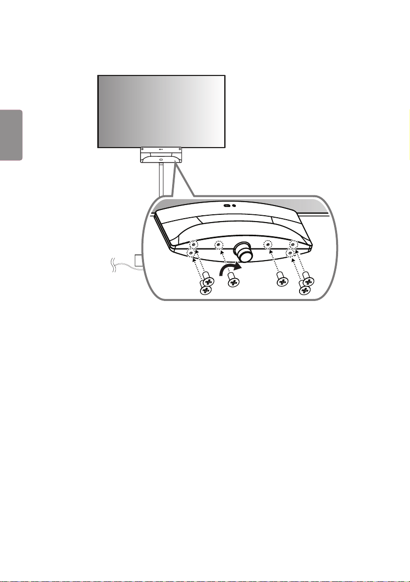
21
Fasten 6 screws (M4 x L8) to the bottom part of the T-con cover.
15
ENG
ENGLISH
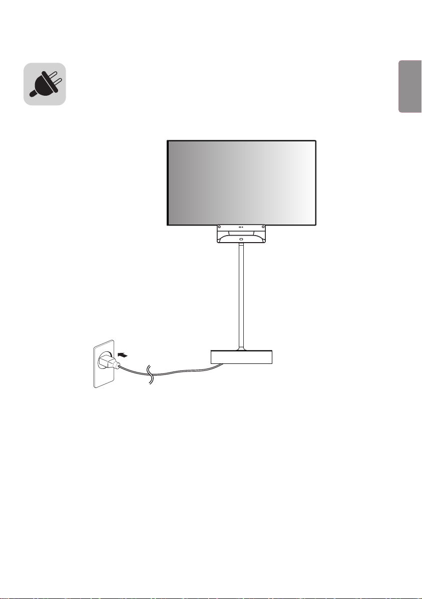
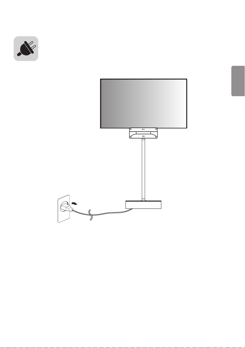
Plug the power cable that is located at the bottom of the stand into a power outlet.