
➔
➔
➔
➔
Stealthbox
®
INSTALLATION GUIDE
SB-F-EXPED/10W6AE, JL AUDIO, Inc 2004
Sheet SKU#011106 Revision6/29/2004 Page 1
for the
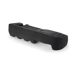
SB-F-EXPED/10W6AE
(1997-2002 Ford Expedition &
1998-2002 Lincoln Navigator)
This Stealthbox is a product which
requires professional installation skills and
tools.
Please read this installation guide thor-
oughly before beginning the project. It
will guide you step by step through the
installation. Several of the steps in this
process may require two people to
accomplish.
It is absolutely vital that the enclosure
be properly mounted to the vehicle
according to these instructions. Failure
to mount the enclosure properly pres-
ents two problems: 1) The sub-bass
performance will suffer due to the
movement of the enclosure caused by
the force exerted by the woofer(s) and
2) A loose enclosure presents a serious
safety hazard in the event of a collision
or sudden deceleration.
Please enjoy your JL Audio Stealthbox
responsibly.
STEP 1:
Remove the tool access panel, from
the passenger’s side rear cargo panel.
Remove all contents.
STEP 2:
Remove the hatch floor sill.
STEP 3:
Remove the cargo hatch ceiling trim.
STEP 4:
Unscrew the pair of cargo net
hooks, from the passenger’ side cargo panel.
STEP 5:
Remove the D-pillar trim.This is the
panel that is directly behind the passenger’s
rear side window.
STEP 6:
Remove the rear passenger’s side
door sill.
START
HERE
Continued on Next Page ➔
www.jlaudio.com
➔
➔

➔➔
➔➔➔
STEP 7: Fold the rear seats forward and remove
the exposed floor trim panel.
STEP 11: Remove the rubber weather seal from
the rear passenger’s door opening.
Cont.
From
Previous
Page
Continued on Next Page ➔
➔
STEP 8: At the rear passenger’s side C-pillar. Lift
the flap covering the upper seat bolt anchor to
expose the mounting bolt.The flap needs to be lift-
ed from the bottom.
STEP 12: Remove the plastic trim off the rear pas-
senger’s side C-Pillar.This is located behind the pas-
senger’s side rear door, in front of the passenger’s
side rear side window.
➔
STEP 13: Remove the large passenger’s side rear
cargo panel.
STEP 14: Using an 8mm socket, remove the pair
of bolts that secures the tool kit partition.
If the vehicle is equipped with the OEM woofer sys-
tem, also remove at this time.
STEP 9: Using a 15mm socket, remove the
mounting bolt of the upper seat belt anchor.
STEP 10: At the bottom of this seat belt assembly,
lift up on the rubber boot cover.
Use a T-45 socket to remove this lower seat belt
anchor mounting bolt.
SB-F-EXPED/10W6AE, JL AUDIO, Inc 2004
Sheet SKU#011106 Revision6/29/2004 Page 2
www.jlaudio.com
➔➔
➔➔➔
STEP 15: Using a razor knife, you need to cut out
the rubber lining that covers the passenger’s side
rear wheel well.
The cut needs to run from the floor at rear of the
wheel well, over the wheel well forward to the C-
pillar and over to the outer sheet metal.
STEP 21: Remove the wax square and run speak-
er wire to the enclosures mounting location.Test
woofer for proper operation.Then connect the
speaker wire to the wire terminal found on the
enclosure.
Cont.
From
Previous
Page
Continued on Next Page ➔
➔
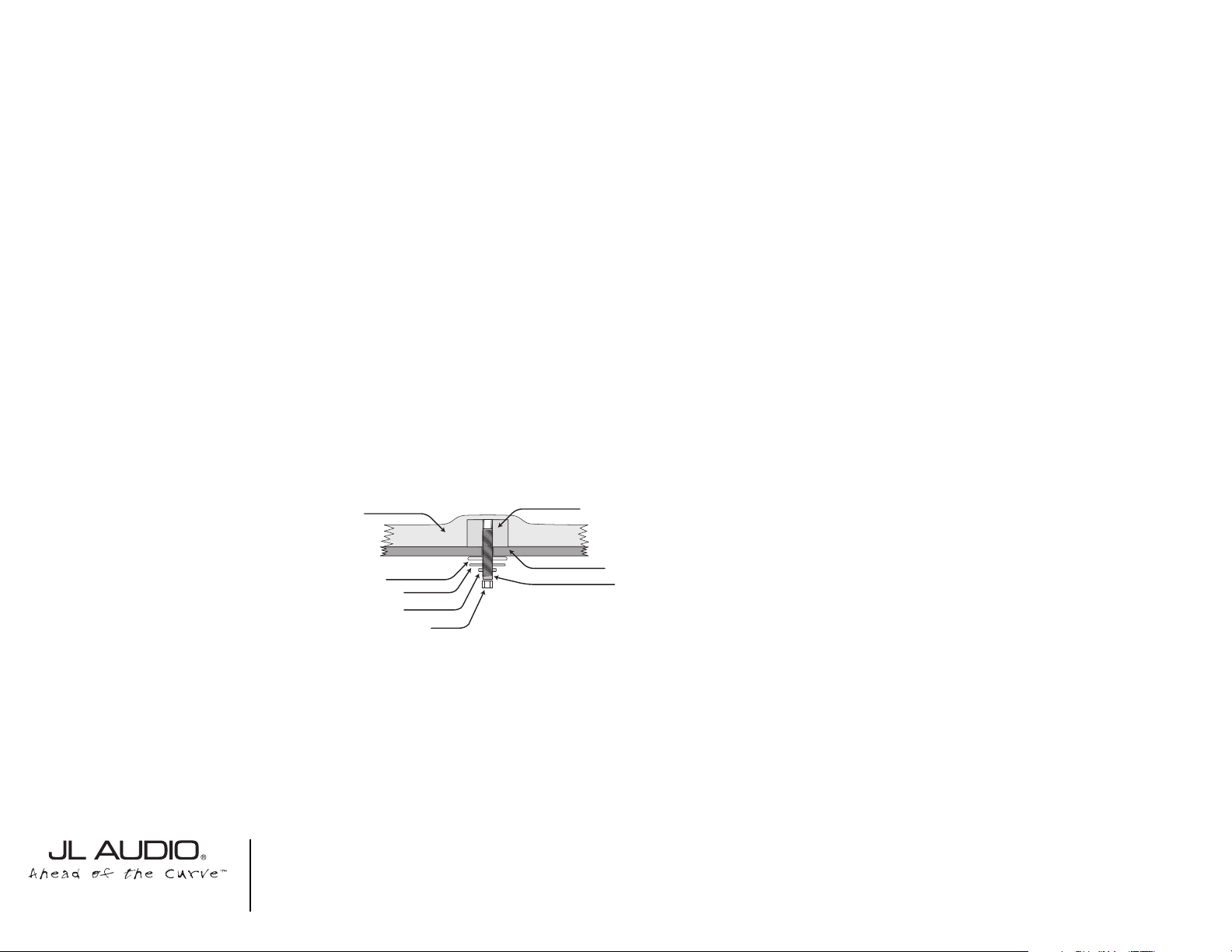
STEP 16: Place the supplied wax square with the
paper removed and sticky side down, in the mount-
ing location of the threaded insert inside the enclo-
sure.
STEALTHBOX WALL
THREADED INSERT
VEHICLE SHEET METAL
FENDER WASHER
SOCKET CUP SET SCREW
LOCK WASHER
FLAT WASHER
HEX NUT
STEP 22: Back out the socket cup set screw to
expose 1-1/2”. Place the enclosure into location,
guiding the socket cup set screw through the drilled
hole.
STEP 23: In these steps, place the supplied fender
washer, flat washer, lock washer and then hex nut
onto the socket cup set screw.
If necessary , back out or in the socket cup set
screw for proper length. Use the least amount of
length.
➔
STEP 24: With an 8mm socket, mount the tool kit
partition that was removed in STEP 14.
STEP 25: Outside the vehicle, flip over the large
cargo panel that was removed in STEP 13.
Remove the clips from the edge of the storage
pocket.
If your Expedition/Navigator is equipped with the
OEM woofer system.You will need this storage
pocket trim from an Expedition(only) that does not
have the OEM woofer system. Check your Ford
Parts Department or local vehicle recycling yard.
STEP 17: Thread in the supplied socket cup set
screw into the enclosure. Allow 1/2” to be exposed.
STEP 18: Place the enclosure into the mounting
location and press firmly down.This to leave an
impression on the wax square from STEP 16.
STEP 19: Remove the enclosure, making sure that
the wax square does stay on the floor.
STEP 20: *CAUTION*
Before drilling, check under the vehicle for
fuel lines, brake lines, exhaust pipes, electri-
cal wiring or any other objects that present
a hazard.Always wear eye protection when
drilling
With a drill and a 1/2” drill bit, drill at the impression
on the wax square as a guide.
SB-F-EXPED/10W6AE, JL AUDIO, Inc 2003
Sheet SKU#011106 Revision6/29/2004 Page 3
www.jlaudio.com
Specifications:
Enclosure Type: Acoustic Suspension(Sealed)
Driver Type: 10W6AE
Nominal Impedance: 3Ω
Cont. Power Handling: 300Watts
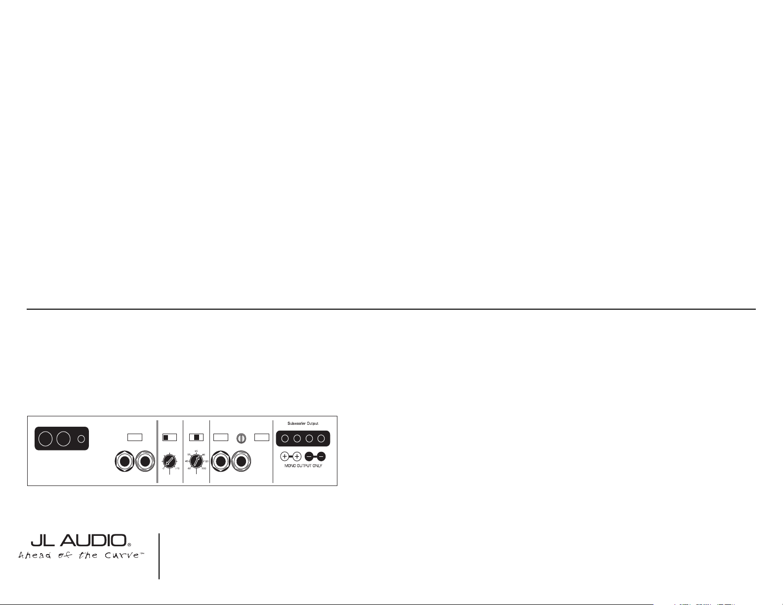
JL Audio recommends using a high quality amplifier such as the JL Audio 250/1. The diagram below shows the recommended
crossover, infrasonic filter and equalizer settings for the 250/1 when being used to power your Stealthbox®.
Included Hardware:
(1) 3/8”-16 X 2-1/4” Socket Set Screw
(1) 3/8” Fender Washer
(1) 3/8” Flat Washer
(1) 3/8” Lock Washer
(1) 3/8”-16 Hex Nut
(1) Wax Square
(1) Upholstered Metal Grille
10369 N. Commerce Pkwy, Miramar, Florida 33025-392 Phone: 954.443.1100 Fax: 954.443.1111
JL AUDIO 250/1
monoblock subwoofer amplifier
Amplifier Input Section
Input Sens.
Input Voltage
Low/High
Left Ch.
Right Ch.
Signal Sensing
Off/On
Output Mode
Full-Range/Low-Pass/High-Pass
Left Ch.
Right Ch.
Amp LP Filter
Mode/Slope
Off/12dB/24dB
Filter Freq. (Hz)
Bass Control
LF Boost (dB)
Off/30Hz
Infrasonic Filter
+1
+13
+3
+7
+10
Preamp Output Section
+12VDC Ground Remote
The JL Audio 250/1 is a very versatile audio component. Please consult the owner’s manual for detailed information
about installing and tuning this amplifier.
➔➔➔
STEP 26: To assemble the grille. Place the supplied
speaker grille into the factory trim ring, that was
removed in STEP 25.
STEP 27: Place the grille/trim ring onto the rear
cargo panel.
STEP 28: Snap the other trim ring onto the grille
assembly and use the clips that were removed in
STEP 25, to secure the grille assembly to the cargo
panel.
STEP 29: Replace the cargo panel into location
and follow STEPS 12 - 1(yes, in reverse order), to
reassemble the vehicle.
➔
SB-F-EXPED/10W6AE, JL AUDIO, Inc 2004
Sheet SKU#011106 Revision6/29/2004 Page 4
www.jlaudio.com
Mid/High Frequency Driver Information:
CONGRATULATIONS!
INSTALL COMPLETE.
XR570-CSi
Front Location Driver Size:
5”x 7”/6”x 8”
Applicable JL Audio Products:
ZR,XR,VR,TR570-CSi,CXi
Rear Location Driver Size:
5”x 7”/6”x 8”
Applicable JL Audio Products:
N/A, due to limited mounting depth.
Cont.
From
Previous
Page
Difficulty Of Installation: