Loading ...
Loading ...
Loading ...
11
ENGLISH
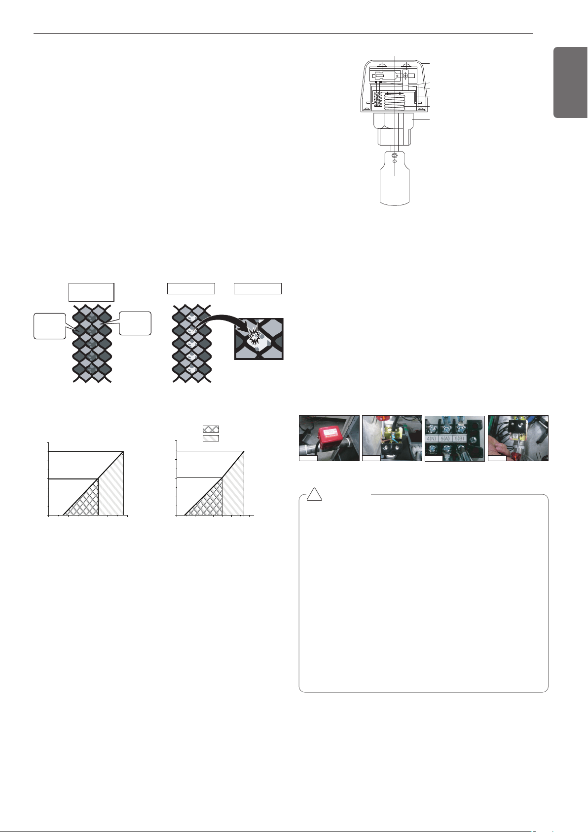
Upper graph is a theoretical value for selection and it may be different
according to specification of strainer.
Head loss of strainer on water pipe
: Suggestion range
: Allowed range
6
4
2
0
0 10 20
25 30 40
02040
50 60 80
8
6
4
2
0
8
GPM
psi
psi
GPM
ARWN121DAS4
ARWN121BAS4
ARWN192DAS4
Flow switch work
• It is recommended to install the flow switch to the water collection
pipe system connecting to the outside unit.
(Flow switch acts as the 1st protection device when the heat water
is not supplied. If a certain level of water does not flow after in-
stalling the flow switch, an error sign of CH24 error will be displayed
on the product and the product will stop operating.)
• When setting the flow switch, it is recommended to use the product
with default set value to satisfy the minimum flow rate of this prod-
uct. (The minimum flow rate range of this product is 50%. Reference
flow rate : 10HP-25.4GPM, 20HP-50.7GPM
• Select the flow switch with the permitted pressure specification con-
sidering the pressure specification of the heat water supply system.
(Control signal from outside unit is AC 220V.)
Strainer on water pipe
To protect the water cooling type product, you must install a strainer
with 50 mesh or more on the heat water supply pipe.
If not installed, it can result in damage of heat exchanger by the follow-
ing situation.
1 Heat water supply within the plate type heat exchanger is com-
posed of multiple small paths.
2 If you do not use a strainer with 50 mesh or more, alien particles
can partially block the water paths.
3 When running the heater, the plate type heat exchanger plays the
role of the evaporator, and at this time, the temperature of the
coolant side drops to drop the temperature of the heat water sup-
ply, which can result in icing point in the water paths.
4 And as the heating process progresses, the water paths can be par-
tially frozen to lead to damage in plate type heat exchanger.
5 As a result of the damage of the heat exchanger from the freezing,
the coolant side and the heat water source side will be mixed to
make the product unusable.
Heat Source
Water
Refrigerant
1. Pollution of
Heat source
2. Partially frozen
3. Damage
DEVICE PROTECTION UNIT
1 inch or
3/4 inch
socket
Cover
Micro-switch
Adjustment screw
Vibration plate
Bellows
Pad
Installation of flow switch
• The flow switch must be installed at the horizontal pipe of the heat
water supply outlet of the product and check the direction of the heat
water flow before the installation. (Picture 1)
• When connecting the flow switch to the product, remove the jump
wire to connect to the communication terminal (5(A) and 5(B)) of the
outside unit control box. (Picture 2, 3) (Open the cover of the flow
switch and check the wiring diagram before connecting the wires.
The wiring method can differ by the manufacturer of the flow
switch.)
• If necessary, adjust the flow rate detection screw after consulting
with an expert and adjust to the minimum flow rate range. (Picture 4)
(Minimum flow rate range of this product is 50%. Adjust the flow
switch to touch the contact point when the flow rate reaches 50% of
the flow rate.)
- Reference flow rate : 10HP-25.4GPM, 20HP-50.7GPM
Picture 1 Picture 2
Picture 3
Picture 4
CAUTION
• If the set value does not satisfy the minimum flow rate or if the
set value is changed by the user arbitrarily, it can result in prod-
uct performance deterioration or serious product problem.
• If the product is operated with the heat water supply not flow-
ing smoothly, it can damage the heat exchanger or cause seri-
ous product problems.
• In case of CH24 or CH180 error, there is a possibility that the
plate type heat exchanger is partially frozen inside. In this case
resolve the issue of partial freezing and then operate the prod-
uct again. (Cause of partial freezing : Insufficient heat water
flux, water not supplied, insufficient coolant, alien particle pene-
trated inside plate type heat exchanger)
• When the product operates while the flow switch touches the
contact point at the flow rate range out of the permitted range,
it can cause product performance deterioration or serious prod-
uct problem.
• Must use the normal closed type flow switch
- Circuit of outside unit is normal closed type.
!
Loading ...
Loading ...
Loading ...