Loading ...
Loading ...
Loading ...
10
ENGLISH
9 The Multi V water will stop due to an abnormality like excessive or
insufficient refrigerant. At such a time, always properly charge the
unit. When servicing, always check the notes concerning both the
piping length and the amount of additional refrigerant.
10 Never perform a pump down. This will not only damage the com-
pressor but also deteriorate the performance.
11 Never use refrigerant to perform an air purge. Always evacuate
using a vacuum pump.
12. Always insulate the piping properly. Insufficient insulation will re-
sult in a decline in heating/cooling performance, drip of condensate
and other such problems.
13. When connecting the refrigerant piping, make sure the service
valves of the Outside Unit is completely closed (the factory setting)
and do not operate it until the refrigerant piping for the Outside and
Indoor Units has been connected, a refrigerant leakage test has
been performed and the evacuation process has been completed.
14. Always use a non-oxidizing brazing material for brazing the parts
and do not use flux. If not, oxidized film can cause clogging or dam-
age to the compressor unit and flux can harm the copper piping or
refrigerant oil.
Ⓐ To Outside Unit
Ⓑ Sealed Piping
A
A
B
WARNING
When installing and moving the air conditioner to another site, be
sure to make recharge refrigerant after perfect evacuation.
•
If a different refrigerant or air is mixed with the original refrigerant, the
refrigerant cycle may malfunction and the unit may be damaged.
• After selecting diameter of the refrigerant pipe to suit total capac-
ity of the indoor unit connected after branching, use an appropriate
branch pipe set according to the pipe diameter of the indoor unit
and the installation pipe drawing.
!
CAUTION
Do not directly connect the drain outlet to the water pipe outlet.
(It can cause problems to the product.)
!
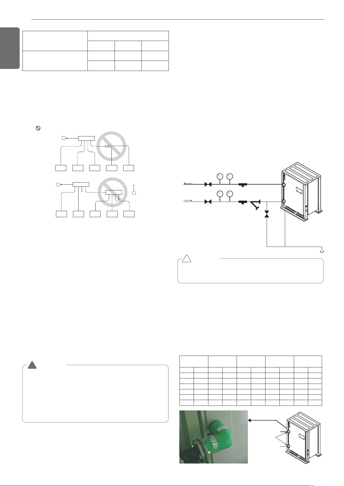
Water pipe connection
• The water pipe should be the same size of the connection on the
product or more.
• If necessary install the insulation material in the water pipe
inlet/outlet to prevent water drop, freeze and to save energy.
(Use the above 20mm(25/32inch) thickness PE insulation mate-
rial.)
• Tightly connect the socket to the water pipe refer to below table
for recommended specification.
(Too much torque may cause the damage of the facility.)
Water pipe
outlet
Gate valve
Gate valve
Service port
Pressure gauge
Temperature gauge
Service port
Strainer
Drain line
Condensed
water drain
Water pipe
Inlet
Water pipe
connection
Water pipe inlet
Water pipe outlet
mm inch (kN) (kgf) (kN) (kgf) (N
.
m) (kgf
.
m)(N
.
m) (kgf
.
m)
12.7 1/2 3.5 350 2.5 250 20 23 5 3.5
19.05 3/4 12 1200 2.5 250 20 2 115 11.5
25.4 1 11.2 1120 4 400 45 4.5 155 15.5
31.8 1 1/4 14.5 1450 6.5 650 87.5 8.75 265 26.5
38.1 1 1/2 16.5 1.7 9.5 0.95 155 16 350 35.5
50.8 2 21.5 2.2 13.5 1.4 255 26 600 61
Pipe thickness Shear stress Tensile stress
Bending
moment
Torque
INSTALLATION OF WATER PIPE
Water pipe system diagram
• The water pressure resistance of the water pipe system of this
product is 1.98MPa(287.18psi).
• When the water pipe passes indoors, make sure to execute heat
insulation on the pipe so that water drops do not form on the
outer side of the water pipe.
• The size of the drain pipe must be equal to or larger than the di-
ameter of the connecting product.
- Always install a trap so that the drained water does not back
flush.
•
Always install a strainer (50Mesh or above) at the entrance of the
water pipe. (When sand, trash, rusted pieces get mixed into the
water supply, it can cause problems to the product due to blocking)
- If On/Off valve is applied, by interlocking with outside unit, it can
save the energy consumption of pump by blocking the water
supply to the outside unit not operating. Select appropriate valve
and install on site if necessary.
• Install a pressure gauge and temperature gauge at the inlet and
outlet of the water pipe.
• Flexible joints must be installed not to cause any leakage from the
vibration of pipes.
• Install a service port to clean the heat exchanger at the each end
of the water inlet and outlet.
• For the components of the water pipe system, always use com-
ponents above the designed water pressure.
6 If the diameters of the branch piping of the designated refrigerant
piping differs, use a pipe cutter to cut the connecting section and
then use an adapter for connecting different diameters to connect
the piping.
7 Always observe the restrictions on the refrigerant piping (such as
rated length, difference in height, and piping diameter).
Failure to do so can result in equipment failure or a decline in heat-
ing/cooling performance.
8 A second branch cannot be made after a header. (These are shown
by .)
Y branch
Header
4 branch 7 branch 10 branch
ARBLB01621, ARBLB03321,
ARBLB07121, ARBLB14521,
ARBLB23220
ARBL054 ARBL057 ARBL1010
ARBL104 ARBL107 ARBL2010
Loading ...
Loading ...
Loading ...