INSTALLATION MANUAL
AIR CONDITIONER
• Please read this installation manual completely before installing the product.
• Installation work must be performed in accordance with the national
wiring standards by authorized personnel only.
• Please retain this installation manual for future reference after reading
it thoroughly.your set and retain it for future reference.
P/NO : MFL68100306
MODELS : ARWB Series
http://www.lghvac.com
www.lg.com
ENGLISH
2
TIPS FOR SAVING ENERGY
Here are some tips that will help you minimize the power consumption
when you use the air conditioner. You can use your air conditioner
more efficiently by referring to the instructions below:
IMPORTANT SAFETY INSTRUC-
TIONS
READ ALL INSTRUCTIONS BEFORE USING THE AP-
PLIANCE.
Always comply with the following precautions to avoid dangerous situ-
ations and ensure peak performance of your product
WARNING
It can result in serious injury or death when the directions are ignored
CAUTION
It can result in minor injury or product damage when the directions are
ignored
WARNING
• Installation or repairs made by unqualified persons can result in haz-
ards to you and othersInstallation of all field wiring and components
MUST conform with local building codes or, in the absence of local
codes, with the National Electrical Code 70 and the National Build-
ing Con-struction and Safety Code or Canadian Electrical code and
National Building Code of Canada.
• Installation or repairs made by unqualified persons can result in haz-
ards to you and others.
• The information contained in the manual is intended for use by a
qualified service technician familiar with safety procedures and
equipped with the proper tools and test instruments.
• Failure to carefully read and follow all instructions in this manual can
result in equipment malfunction, property damage, personal injury
and/or death.
Installation
• Have all electric work done by a licensed electrician according to "Elec-
tric Facility Engineering Standard" and "Interior Wire Regulations" and the
instructions given in this manual and always use a special circuit.
- If the power source capacity is inadequate or electric work is per-
formed improperly, electric shock or fire may result.
• Ask the dealer or an authorized technician to install the air conditioner.
- Improper installation by the user may result in water leakage, electric
shock, or fire.
• Always ground the product.
- There is risk of fire or electric shock.
• Always intstall a dedicated circuit and breaker.
- Improper wiring or installation may cause fire or electric shock.
• For re-installation of the installed product, always contact a dealer or an
Authorized Service Center.
- There is risk of fire, electric shock, explosion, or injury.
• Do not install, remove, or re-install the unit by yourself (customer).
- There is risk of fire, electric shock, explosion, or injury.
• Do not store or use flammable gas or combustibles near the air condi-
tioner.
- There is risk of fire or failure of product.
• Use the correctly rated breaker or fuse.
- There is risk of fire or electric shock.
• Do not install the unit at the outdoors.
- Otherwise it may cause fire, electric shock and trouble.
• Do not install the product on a defective installation stand.
- It may cause injury, accident, or damage to the product.
• Use a vacuum pump or Inert(nitrogen) gas when doing leakage test or
air purge. Do not compress air or Oxygen and do not use Flammable
gases. Otherwise, it may cause fire or explosion.
- There is the risk of death, injury, fire or explosion.
• When installing and moving the air conditioner to another site, do not
charge it with a different refrigerant from the refrigerant specified on
the unit.
- If a different refrigerant or air is mixed with the original refrigerant, the
refrigerant cycle may malfunction and the unit may be damaged.
• Do not reconstruct to change the settings of the protection devices.
- If the pressure switch, thermal switch, or other protection device is
shorted and operated forcibly, or parts other than those specified by
LGE are used, fire or explosion may result.
• Ventilate before operating air conditioner when gas leaked out.
- It may cause explosion, fire, and burn.
• Securely install the cover of control box and the panel.
- If the cover and panel are not installed securely, dust or water may
enter the outside unit and fire or electric shock may result.
• If the air conditioner is installed in a small room, measures must be
taken to prevent the refrigerant concentration from exceeding the safety
limit when the refrigerant leaks.
- Consult the dealer regarding the appropriate measures to prevent the
safety limit from being exceeded. Should the refrigerant leak and cause
the safety limit to be exceeded, harzards due to lack of oxygen in the
room could result.
Operation
• Do not damage or use an unspecified power cord.
- There is risk of fire, electric shock, explosion, or injury.
• Use a dedicated outlet for this appliance.
- There is risk of fire or electrical shock.
• Be cautious that water could not enter the product.
- There is risk of fire, electric shock, or product damage.
• Do not touch the power switch with wet hands.
- There is risk of fire, electric shock, explosion, or injury.
• When the product is soaked (flooded or submerged), contact an Authorized
Service Center.
- There is risk of fire or electric shock.
• Be cautious not to touch the sharp edges when installing.
- It may cause injury.
• Take care to ensure that nobody could step on or fall onto the outside unit .
- This could result in personal injury and product damage.
• Do not open the inlet grille of the product during operation. (Do not touch the
electrostatic filter, if the unit is so equipped.)
- There is risk of physical injury, electric shock, or product failure.
!
!
!
ENGLISH
• Do not cool excessively indoors. This may be harmful for your health
and may consume more electricity.
• Block sunlight with blinds or curtains while you are operating the air
conditioner.
• Keep doors or windows closed tightly while you are operating the air
conditioner.
• Adjust the direction of the air flow vertically or horizontally to circulate
indoor air.
• Open windows regularly for ventilation as the indoor air quality may
deteriorate if the air conditioner is used for many hours.
• Clean the air filter once every 2 weeks. Dust and impurities collected
in the air filter may block the air flow or weaken the cooling / dehu-
midifying functions.
For your records
Staple your receipt to this page in case you need it to prove the date of
purchase or for warranty purposes. Write the model number and the
serial number here:
Model number :
Serial number :
You can find them on a label on the side of each unit.
Dealer’s name :
Date of purchase :
3
CAUTION
Installation
• Always check for gas (refrigerant) leakage after installation or repair of product.
- Low refrigerant levels may cause failure of product.
• Do not install the product where the noise or hot air from the outside unit could
damage the neighborhoods.
- It may cause a problem for your neighbors.
• Keep level even when installing the product.
- To avoid vibration or water leakage.
• Do not install the unit where combustible gas may leak.
- If the gas leaks and accumulates around the unit, an explosion may result.
• Use power cables of sufficient current carrying capacity and rating.
- Cables that are too small may leak, generate heat, and cause a fire.
• Do not use the product for special purposes, such as preserving foods, works of
art, etc. It is a consumer air conditioner, not a precision refrigeration system.
- There is risk of damage or loss of property.
• When installting the unit in a hospital, communication station, or similar place,
provide sufficient protection against noise.
-
The inverter equipment, private power generator, high-frequency medical
equipment, or radio communication equipment may cause the air condi-
tioner to operate erroneously, or fail to operate. On the other hand, the air
conditioner may affect such equipment by creating noise that disturbs med-
ical treatment or image broadcasting.
Operation
• Do not use the air conditioner in special environments.
-
Oil, steam, sulfuric smoke, etc. can significantly reduce the performance of the air
conditioner or damage its parts.
• Do not block the inlet or outlet.
- It may cause failure of appliance or accident.
• Make the connections securely so that the outside force of the cable may not be
applied to the terminals.
- Inadequate connection and fastening may generate heat and cause a fire.
• Be sure the installation area does not deteriorate with age.
- If the base collapses, the air conditioner could fall with it, causing property
damage, product failure, or personal injury.
•
Install and insulate the drain hose to ensure that water is drained away properly
based on the installation manual.
- A bad connection may cause water leakage.
• Be very careful about product transportation.
- Only one person should not carry the product if it weighs more than 20 kg.
-
Some products use PP bands for packaging. Do not use any PP bands for a means
of transportation. It is dangerous.
- Do not touch the heat exchanger fins. Doing so may cut your fingers.
- When transporting the outside unit , suspending it at the specified positions on
the unit base. Also support the outside unit at four points so that it cannot slip
sideways.
• Safely dispose of the packing materials.
-
Packing materials, such as nails and other metal or wooden parts, may cause stabs
or other injuries.
-
Tear apart and throw away plastic packaging bags so that children may not play with
them. If children play with a plastic bag which was not torn apart, they face the risk
of suffocation.
• Turn on the power at least 6 hours before starting operation.
- Starting operation immediately after turning on the main power switch can re-
sult in severe damage to internal parts. Keep the power switch turned on dur-
ing the operational season.
• Do not touch any of the refrigerant piping during and after operation.
- It can cause a burn or frostbite.
• Do not operate the air conditioner with the panels or guards removed.
- Rotating, hot, or high-voltage parts can cause injuries.
• Do not directly turn off the main power switch after stopping operation.
- Wait at least 5 minutes before turning off the main power switch. Otherwise it
may result in water leakage or other problems.
•
Auto-addressing should be done in condition of connecting the power of all indoor and
outdoour units. Auto-addressing should also be done in case of changing the indoor
unit PCB.
• Use a firm stool or ladder when cleaning or maintaining the air conditioner.
- Be careful and avoid personal injury.
!
ENGLISH
TABLE OF CONTENTS
2 TIPS FOR SAVING ENERGY
2 IMPORTANT SAFETY INSTRUCTIONS
4 INSTALLATION PROCESS
4 OUTSIDE UNITS INFORMATION
6 ALTERNATIVE REFRIGERANT R410A
6 SELECT THE BEST LOCATION
8 INSTALLATION SPACE
8 WATER CONTROL
9 LIFTING METHOD
9 INSTALLATION
12 REFRIGERANT PIPING INSTALLATION
15 DEVICE PROTECTION UNIT
15 INSTALLATION OF WATER PIPE
16 PIPE CONNECTIONS BETWEEN INDOOR
AND OUTSIDE UNIT
24 ELECTRICAL WIRING
31 HR UNIT PCB
38 TEST RUN
42 CAUTION FOR REFRIGERANT LEAK
43 COOLING TOWER APPLIED METHOD
43 WATER SOLENOID VALVE CONTROL
4
ENGLISH
The foundation must be level even
Outside unit foundation work
Avoid short circuits and ensure
sufficient space is allowed for service
Installation of outside unit
Refer to automatic addressing flowchart
Automatic addressing of indoor unit
In the final check for 24hours at 3.8 MPa(38.7 kgf/cm
2
) there
must be no drop in pressure.
Airtight test
Multiple core cable must not be used.
(suitable cable should be selected)
Electrical work
(connection circuits and drive circuits)
Make sure no gaps are left where
the insulating materials are joined
Heat insulation work
Make sure airflow is sufficient
Duct work
Adjust to downward gradient
Drain pipe work
Special attention to dryness,
cleanness and tightness
Refrigerant piping work
Check model name to
make sure the fitting
is made correctly
Installation of indoor unit
Take account of gradient
of drain piping
Sleeve and insert work
Make connection clearly between outside, indoor,
remote controller and option.
Preparation of contract drawings
Indicate clearly who will be responsible for switch setting.
Determination of division work
The vacuum pump used must have a capacity of reaching at least
5 torr, more than 1 hour
Vacuum drying
Recharge correctly as calculated in this manual. and record the
amount of added refrigerant
Additional charge of refrigerant
Make sure there are no gaps left between the facing materials
used on the ceiling
Fit facing panels
Run each indoor unit in turn to make sure the pipe work
has been fitted correctly
Test run adjustment
Explain the use of the system as clearly as possible to your customer and
make sure all relevant documentation is in order
Transfer to customer with explanation
Preheat the crank case with the electrical heater for more than 6 hours.
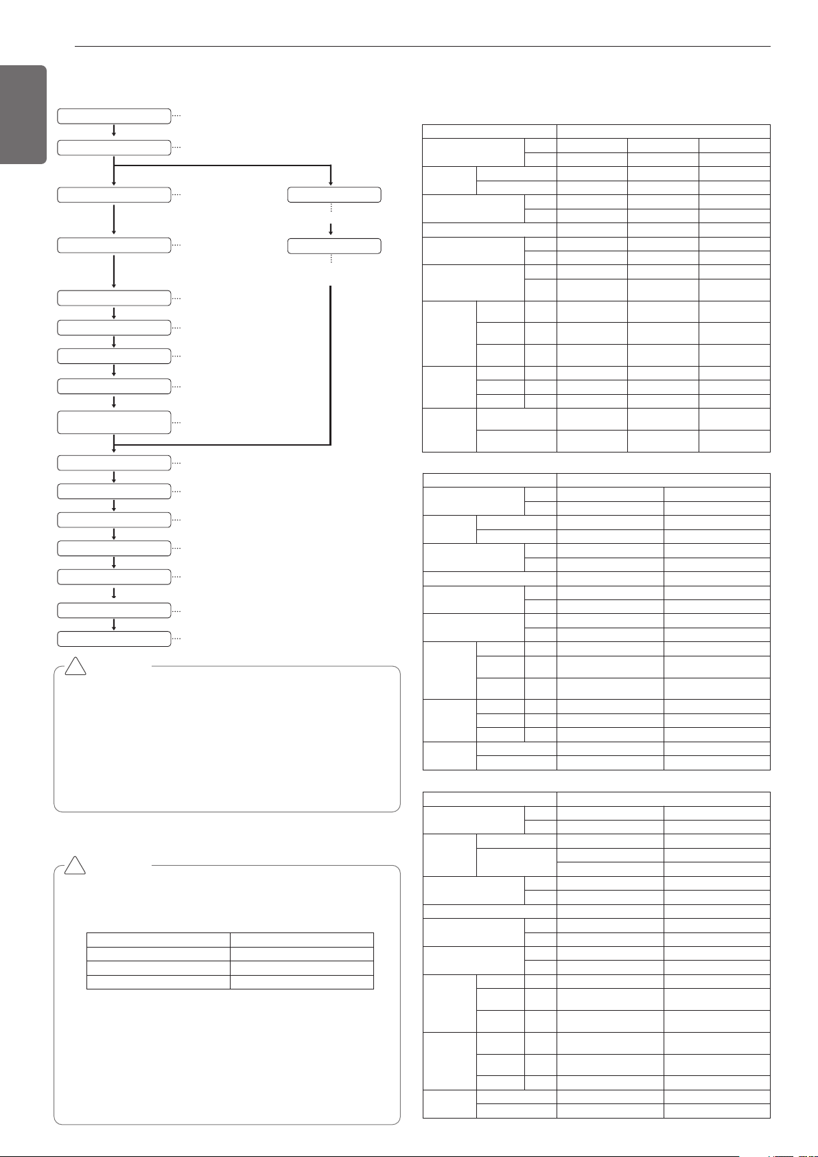
CAUTION
• The above list indicates the order in which the individual work opera-
tions are normally carried out but this order may be varied where
local conditions warrants such change.
• The thickness of the piping should comply with the relevant local and
national regulations for the designed pressure 3.8Mpa(551.1psi).
• Since R410A is a mixed refrigerant, the required additional
refrigerant must be charged in its liquid state.(If the refrigerant is
charged in its gaseous state, its composition changes and the sys-
tem will not work properly.)
!
CAUTION
Notes: *
We can guarantee the operation only within 130% Combina-
tion. If you want to connect more than 130% combination,
please contact us and discuss the requirement like below.
• If the operation of indoor unit is more than 130%, low airflow
operation is recommended in all the indoor units.
• If the operation of indoor unit is more than 130%, additional re-
frigerant is needed according to the Aheadquarter guidance.
• Over 130%, capacity is same as capacity of 130%, Same re-
mark is valid for power input.
•
Ratio of the running Indoor Units to the Outside: Within 10 ~ 100%
•
A combination operation over 100% cause to reduce each indoor unit capacity.
Combination Ratio(50~200%)
Outside Unit Number Connection Ratio
Single outside unit s 200%
Double outside unit s 160%
More than Triple outside unit s
130%
!
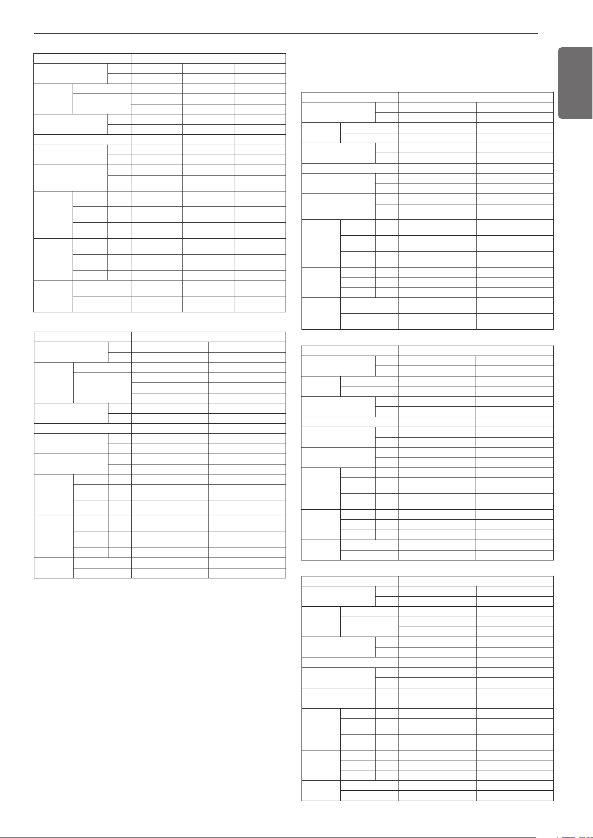
OUTSIDE UNITS INFORMATION
INSTALLATION PROCESS
Power Supply : 3Ø, 460V, 60Hz
Model Name : ARWB***DAS4
Unit
1 Unit
System Capacity
HP 8 10 12
TON 6 8 10
Model
Combination Unit ARWB072DAS4 ARWB096DAS4 ARWB121DAS4
Independent Unit ARWB072DAS4 ARWB096DAS4 ARWB121DAS4
Refrigerant Precharged Amount
kg
5.8 5.8 5.8
lbs
12.8 12.8 12.8
Maximum Connectable Number of Indoor Units
13 16 20
Net Weight
kg
127 x 1 127 x 1 127 x 1
lbs
280 x 1 280 x 1 280 x 1
Dimensions(WxHxD)
mm
755 × 997 × 500 755 × 997 × 500 755 × 997 × 500
inch
(29-23/32 x 39-1/4 x
19-11/16) x 1
(29-23/32 x 39-1/4 x
19-11/16) x 1
(29-23/32 x 39-1/4 x
19-11/16) x 1
Refrigerant
Connecting
Pipes
Liquid Pipes mm(inch)
9.52(3/8) 9.52(3/8) 12.7(1/2)
Low Pressure
Gas Pipes
mm(inch)
22.7(7/8) 22.7(7/8) 25.4(1)
High Pressure
Gas Pipes
mm(inch)
19.05(3/4) 19.05(3/4) 19.05(3/4)
Water
Connecting
Pipes
Inlet mm(inch)
PT40(1-1/2)(Internal thread) PT40(1-1/2)(Internal thread) PT40(1-1/2)(Internal thread)
Outlet mm(inch)
PT40(1-1/2)(Internal thread) PT40(1-1/2)(Internal thread) PT40(1-1/2)(Internal thread)
Drain Outlet mm(inch)
PT20(3/4)(external thread) PT20(3/4)(external thread) PT20(3/4)(external thread)
Temp. range of
Circulation water
Cooling
10°C ~ 45°C
(50°F ~ 113°F)
10°C ~ 45°C
(50°F ~ 113°F)
10°C ~ 45°C
(50°F ~ 113°F)
Heating
-5°C ~ 45°C
(23°F ~ 113°F)
-5°C ~ 45°C
(23°F ~ 113°F)
-5°C ~ 45°C
(23°F ~ 113°F)
Unit 1 Unit
System Capacity
HP 14 18
TON 12 14
Model
Combination Unit ARWB144DAS4 ARWB168DAS4
Independent Unit ARWB144DAS4 ARWB168DAS4
Refrigerant Precharged Amount
kg 3 3
lbs 6.6 6.6
Maximum Connectable Number of Indoor Units
23 29
Net Weight
kg 140 x 1 140 x 1
lbs 309 x 1 309 x 1
Dimensions(WxHxD)
mm 755 × 997 × 500 755 × 997 × 500
inch (29-23/32 x 39-1/4 x 19-11/16) x 1 (29-23/32 x 39-1/4 x 19-11/16) x 1
Refrigerant
Connecting
Pipes
Liquid Pipes mm(inch) 12.7(1/2) 12.7(1/2)
Low Pressure
Gas Pipes
mm(inch) 28.58(1-1/8) 28.58(1-1/8)
High Pressure
Gas Pipes
mm(inch) 19.05(3/4) 19.05(3/4)
Water
Connecting
Pipes
Inlet mm(inch) PT40(1-1/2)(Internal thread) PT40(1-1/2)(Internal thread)
Outlet mm(inch) PT40(1-1/2)(Internal thread) PT40(1-1/2)(Internal thread)
Drain Outlet mm(inch) PT20(3/4)(external thread) PT20(3/4)(external thread)
Temp. range of
Circulation water
Cooling 10°C ~ 45°C(50°F ~ 113°F) 10°C ~ 45°C(50°F ~ 113°F)
Heating -5°C ~ 45°C(23°F ~ 113°F) -5°C ~ 45°C(23°F ~ 113°F)
Unit 1 Unit / 2 Unit
System Capacity
HP 20 24
TON 16 20
Model
Combination Unit ARWB192DAS4 ARWB240DAS4
Independent Unit
ARWB192DAS4 ARWB144DAS4
ARWB096DAS4
Refrigerant Precharged Amount
kg 3 3.0+5.8
lbs 6.6 6.6+12.8
Maximum Connectable Number of Indoor Units
32 39
Net Weight
kg 140 x 1 (140 x 1) + (127 x 1)
lbs 309 x 1 (309 x 1) + (280 x 1)
Dimensions(WxHxD)
mm 755 × 997 × 500 (755 × 997 × 500) x 2
inch (29-23/32 x 39-1/4 x 19-11/16) x 1 (29-23/32 x 39-1/4 x 19-11/16) x 2
Refrigerant
Connecting
Pipes
Liquid Pipes mm(inch) 12.7(1/2) 19.05(3/4)
Low Pressure
Gas Pipes
mm(inch) 28.58(1-1/8) 34.9(1-3/8)
High Pressure
Gas Pipes
mm(inch) 19.05(3/4) 28.58(1-1/8)
Water
Connecting
Pipes
Inlet mm(inch) PT40(1-1/2)(Internal thread) PT40(1-1/2)(Internal thread)
Outlet mm(inch) PT40(1-1/2)(Internal thread) PT40(1-1/2)(Internal thread)
Drain Outlet mm(inch) PT20(3/4)(external thread) PT20(3/4)(external thread)
Temp. range of
Circulation water
Cooling 10°C ~ 45°C(50°F ~ 113°F) 10°C ~ 45°C(50°F ~ 113°F)
Heating -5°C ~ 45°C(23°F ~ 113°F) -5°C ~ 45°C(23°F ~ 113°F)
5
ENGLISH
Power Supply : 3Ø, 208/230V, 60Hz
Model Name : ARWB***BAS4
Unit 2 Unit
System Capacity
HP 28 34 38
TON 24 28 32
Model
Combination Unit ARWN288DAS4 ARWN336DAS4 ARWN384DAS4
Independent Unit
ARWN168DAS4 ARWN168DAS4 ARWN192DAS4
ARWN121DAS4 ARWN168DAS4 ARWN192DAS4
Refrigerant Precharged Amount
kg 3.0 + 5.8 3.0+3.0 3.0+3.0
lbs 6.6+12.8 6.6+6.6 6.6+6.6
Maximum Connectable Number of Indoor Units
45 55 61
Net Weight
kg (140 x 1) + (127 x 1) 140 x2 140 x2
lbs (309 x 1) + (280 x 1) 309 x2 309 x2
Dimensions(WxHxD)
mm (755 × 997 × 500) x 2 (755 × 997 × 500) x 2 (755 × 997 × 500) x 2
inch
29-23/32 x 39-1/4 x
19-11/16) x 2
(29-23/32 x 39-1/4 x
19-11/16) x 2
29-23/32 x 39-1/4 x
19-11/16) x 2
Refrigerant
Connecting
Pipes
Liquid Pipes mm(inch) 19.05(3/4) 19.05(3/4) 19.05(3/4)
Low Pressure
Gas Pipes
mm(inch) 34.9(1-3/8) 34.9(1-3/8) 41.3(1-5/8)
High Pressure
Gas Pipes
mm(inch) 28.58(1-1/8) 28.58(1-1/8) 34.9(1-3/8)
Water
Connecting
Pipes
Inlet mm(inch)
PT40(1-1/2)(Internal thread) PT40(1-1/2)(Internal thread) PT40(1-1/2)(Internal thread)
Outlet mm(inch)
PT40(1-1/2)(Internal thread) PT40(1-1/2)(Internal thread) PT40(1-1/2)(Internal thread)
Drain Outlet mm(inch)
PT20(3/4)(external thread) PT20(3/4)(external thread) PT20(3/4)(external thread)
Temp. range of
Circulation water
Cooling
10°C ~ 45°C
(50°F ~ 113°F)
10°C ~ 45°C
(50°F ~ 113°F)
10°C ~ 45°C
(50°F ~ 113°F)
Heating
-5°C ~ 45°C
(23°F ~ 113°F)
-5°C ~ 45°C
(23°F ~ 113°F)
-5°C ~ 45°C
(23°F ~ 113°F)
Unit 3 Unit
System Capacity
HP 46 54
TON 40 48
Model
Combination Unit ARWN480DAS4 ARWN576DAS4
Independent Unit
ARWN192DAS4 ARWN192DAS4
ARWN144DAS4 ARWN192DAS4
ARWN144DAS4 ARWN192DAS4
Refrigerant Precharged Amount
kg 3.0+3.0+3.0 3.0+3.0+3.0
lbs 6.6+6.6+6.6 6.6+6.6+6.6
Maximum Connectable Number of Indoor Units
64 64
Net Weight
kg 140 x3 140 x3
lbs 309 x3 309 x3
Dimensions(WxHxD)
mm (755 × 997 × 500) x 3 (755 × 997 × 500) x 3
inch (29-23/32 x 39-1/4 x 19-11/16) x 3 (29-23/32 x 39-1/4 x 19-11/16) x 3
Refrigerant
Connecting
Pipes
Liquid Pipes mm(inch) 19.05(3/4) 19.05(3/4)
Low Pressure
Gas Pipes
mm(inch) 41.3(1-5/8) 41.3(1-5/8)
High Pressure
Gas Pipes
mm(inch) 34.9(1-3/8) 34.9(1-3/8)
Water
Connecting
Pipes
Inlet mm(inch) PT 40+PT40(1-1/2)(Internal thread) PT 40+PT40(1-1/2)(Internal thread)
Outlet mm(inch) PT 40+PT40(1-1/2)(Internal thread) PT 40+PT40(1-1/2)(Internal thread)
Drain Outlet mm(inch) PT20(3/4)(external thread) PT20(3/4)(external thread)
Temp. range of
Circulation water
Cooling 10°C ~ 45°C(50°F ~ 113°F) 10°C ~ 45°C(50°F ~ 113°F)
Heating -5°C ~ 45°C(23°F ~ 113°F) -5°C ~ 45°C(23°F ~ 113°F)
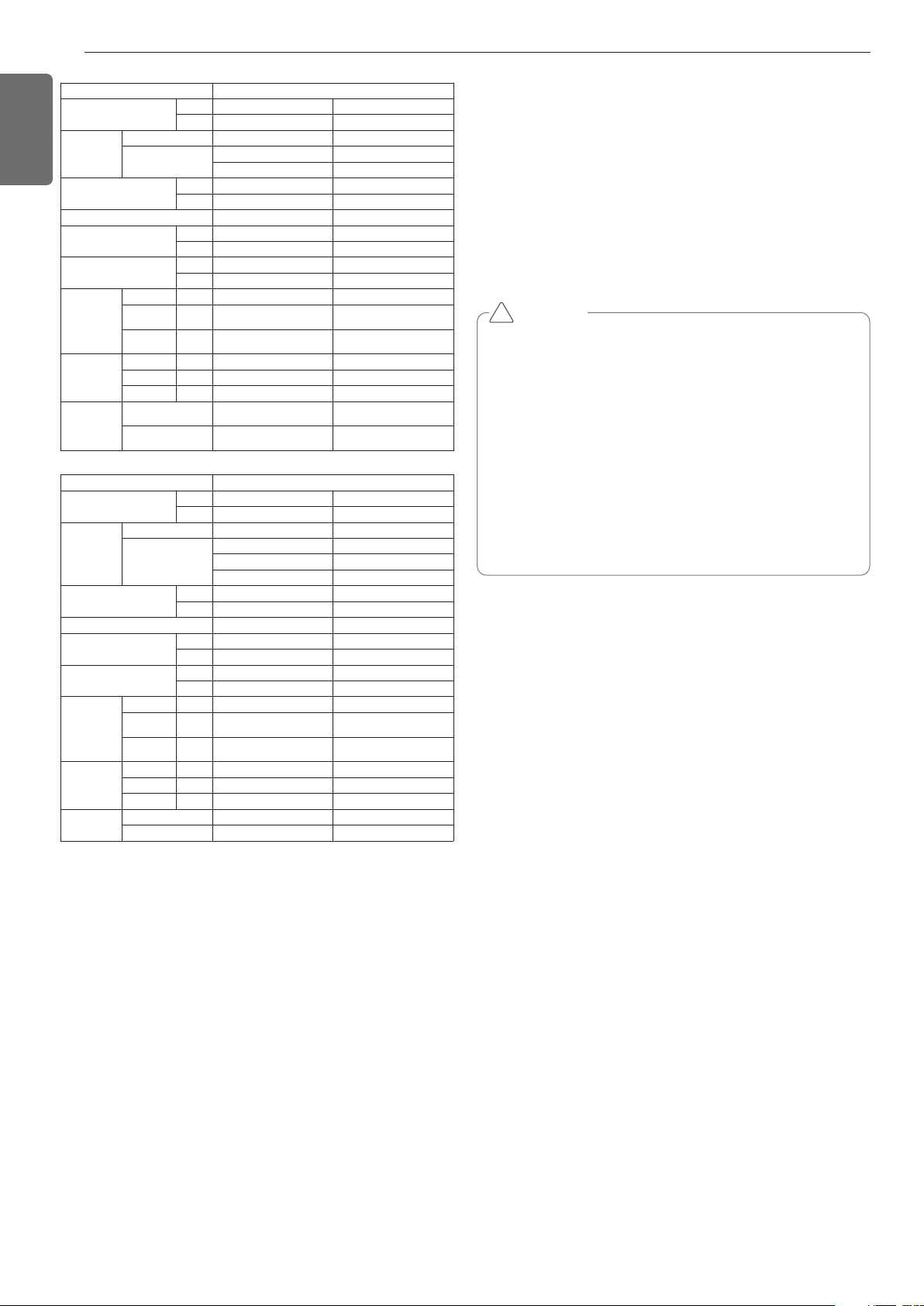
Unit 1 Unit
System Capacity
HP 8 10
TON 6 8
Model
Combination Unit ARWB072BAS4 ARWB096BAS4
Independent Unit ARWB072BAS4 ARWB096BAS4
Refrigerant Precharged Amount
kg 5.8 5.8
lbs 12.8 12.8
Maximum Connectable Number of Indoor Units
13 16
Net Weight
kg 127x1 127x1
lbs 280x1 280x1
Dimensions(WxHxD)
mm 755x997x500 755x997x500
inch
(29-23/32x39-1/4x
19-11/16)x1
(29-23/32x39-1/4x
19-11/16)x1
Refrigerant
Connecting
Pipes
Liquid Pipes mm(inch) 9.52(3/8) 9.52(3/8)
Low Pressure
Gas Pipes
mm(inch) 22.7(7/8) 22.7(7/8)
High Pressure
Gas Pipes
mm(inch) 19.05(3/4) 19.05(3/4)
Water
Connecting
Pipes
Inlet mm(inch) PT40(1-1/2)(Internal thread) PT40(1-1/2)(Internal thread)
Outlet mm(inch) PT40(1-1/2)(Internal thread) PT40(1-1/2)(Internal thread)
Drain Outlet mm(inch) PT20(3/4)(external thread) PT20(3/4)(external thread)
Temp. range of
Circulation water
Cooling
10°C ~ 45°C
(50°F ~ 113°F)
10°C ~ 45°C
(50°F ~ 113°F)
Heating
-5°C ~ 45°C
(23°F ~ 113°F)
-5°C ~ 45°C
(23°F ~ 113°F)
Unit 1 Unit
System Capacity
HP 12 14
TON 10 12
Model
Combination Unit ARWB121BAS4 ARWB144BAS4
Independent Unit ARWB121BAS4 ARWB144BAS4
Refrigerant Precharged Amount
kg 5.8 5.8
lbs 12.8 12.8
Maximum Connectable Number of Indoor Units
20 23
Net Weight
kg 127x1 127x1
lbs 280x1 280x1
Dimensions(WxHxD)
mm 755x997x500 755x997x500
inch (29-23/32x39-1/4x19-11/16)x1 (29-23/32x39-1/4x19-11/16)x1
Refrigerant
Connecting
Pipes
Liquid Pipes mm(inch) 12.7(1/2) 12.7(1/2)
Low Pressure
Gas Pipes
mm(inch) 25.4(1) 28.58(1-1/8)
High Pressure
Gas Pipes
mm(inch) 19.05(3/4) 19.05(3/4)
Water
Connecting
Pipes
Inlet mm(inch) PT40(1-1/2)(Internal thread) PT40(1-1/2)(Internal thread)
Outlet mm(inch) PT40(1-1/2)(Internal thread) PT40(1-1/2)(Internal thread)
Drain Outlet mm(inch) PT20(3/4)(external thread) PT20(3/4)(external thread)
Temp. range of
Circulation water
Cooling 10°C ~ 45°C(50°F ~ 113°F) 10°C ~ 45°C(50°F ~ 113°F)
Heating -5°C ~ 45°C(23°F ~ 113°F) -5°C ~ 45°C(23°F ~ 113°F)
Unit 2 Unit
System Capacity
HP 18 20
TON 14 16
Model
Combination Unit ARWB168BAS4 ARWB192BAS4
Independent Unit
ARWB096BAS4 ARWB121BAS4
ARWB072BAS4 ARWB072BAS4
Refrigerant Precharged Amount
kg 5.8+5.8 5.8+5.8
lbs 12.8+12.8 12.8+12.8
Maximum Connectable Number of Indoor Units
29 32
Net Weight
kg 127x2 127x2
lbs 280x2 280x2
Dimensions(WxHxD)
mm (755x997x500)x2 (755x997x500)x2
inch (29-23/32x39-1/4x19-11/16)x2 (29-23/32x39-1/4x19-11/16)x2
Refrigerant
Connecting
Pipes
Liquid Pipes mm(inch) 12.7(1/2) 12.7(1/2)
Low Pressure
Gas Pipes
mm(inch) 28.58(1-1/8) 28.58(1-1/8)
High Pressure
Gas Pipes
mm(inch) 19.05(3/4) 19.05(3/4)
Water
Connecting
Pipes
Inlet mm(inch) PT40(1-1/2)(Internal thread) PT40(1-1/2)(Internal thread)
Outlet mm(inch) PT40(1-1/2)(Internal thread) PT40(1-1/2)(Internal thread)
Drain Outlet mm(inch) PT20(3/4)(external thread) PT20(3/4)(external thread)
Temp. range of
Circulation water
Cooling 10°C ~ 45°C(50°F ~ 113°F) 10°C ~ 45°C(50°F ~ 113°F)
Heating -5°C ~ 45°C(23°F ~ 113°F) -5°C ~ 45°C(23°F ~ 113°F)
6
ENGLISH
CAUTION
• The wall thickness of the piping should comply with the relevant
local and national regulations for the designed pressure
3.8Mpa(551.1psi).
• Since R410A is a mixed refrigerant, the required additional
refrigerant must be charged in its liquid state.
If the refrigerant is charged in its gaseous state, its composition
changes and the system will not work properly.
• Do not place the refrigerant container under the direct rays of the
sun to prevent it from exploding.
• For high-pressure refrigerant, any unapproved pipe must not be
used.
• Do not heat pipes more than necessary to prevent them from
softening.
• Be careful not to install wrongly to minimize economic loss
because it is expensive in comparison with R22.
!
SELECT THE BEST LOCATION
Select space for installing outside unit , which will meet the following
conditions:
• With strength which bears weight of unit
• With space for air passage and service work
Don't install the unit at the space where generation, inflow, stagna-
tion, and leak of combustible gas is expected.
• Avoid unit installation in a place where acidic solution and spray (sul-
fur) are often used.
• Location with no leakage of combustible gas
• Recommend the outside unit to be installed within
0~40°C(32~104°F).
• Location with installation or service work space (Refer to required
space)
• Do not use the outside unit under any special environment where oil,
steam and sulfuric gas exist.
• Install in a separate machine room not exposed to external air
- Establish an anti-freeze plan for the water supply when the product
is stopped during the winter.
- Install the product so that the noise from the machine room is not
transferred outsides
• The floor of the machine room must be water proof.
• Drainage must be installed in the machine room to process the water
drainage.
• Install a floor slope to make the drainage smooth.
• Avoid installing the outside unit in the location with following condi-
tions.
• Location where corrosive gas such as acidic gas is generated.
(It may cause the refrigerant leakage by corrosion of the pipe.)
• Location where electromagnetic waves happen.
(It may cause the abnormal operation by control parts disorder.)
• Location to be able to leak the combustible gas
• Location with carbon fiber or combustible dust.
• Location with the combustible material like thinner or gasoline.
(It may cause a fire by leaking the gas near the product.)
ALTERNATIVE REFRIGERANT R410A
The refrigerant R410A has the property of higher operating pressure in
comparison with R22.
Therefore, all materials have the characteristics of higher resisting
pressure than R22 ones and this characteristic should be also consid-
ered during the installation.
R410A is an azeotrope of R32 and R125 mixed at 50:50, so the ozone
depletion potential (ODP) of R410A is 0.
These days the developed countries have approved it as the environ-
ment-friendly refrigerant and encouraged to use it widely to prevent
environment pollution.
Unit 3 Unit
System Capacity
HP
36 42
TON
30 36
Model
Combination Unit
ARWB360BAS4 ARWB432BAS4
Independent Unit
ARWB144BAS4 ARWB144BAS4
ARWB144BAS4 ARWB144BAS4
ARWB072BAS4 ARWB144BAS4
Refrigerant Precharged Amount
kg
5.8+5.8+5.8 5.8+5.8+5.8
lbs
12.8+12.8+12.8 12.8+12.8+12.8
Maximum Connectable Number of Indoor Units
58 64
Net Weight
kg
127x3 127x3
lbs
280x3 280x3
Dimensions(WxHxD)
mm
(755x997x500)x3 (755x997x500)x3
inch
(29-23/32x39-1/4x19-11/16)x3 (29-23/32x39-1/4x19-11/16)x3
Refrigerant
Connecting
Pipes
Liquid Pipes mm(inch)
19.05(3/4) 19.05(3/4)
Low Pressure
Gas Pipes
mm(inch)
41.3(1-5/8) 41.3(1-5/8)
High Pressure
Gas Pipes
mm(inch)
34.9(1-3/8) 34.9(1-3/8)
Water
Connecting
Pipes
Inlet mm(inch)
PT40(1-1/2)(Internal thread) PT40(1-1/2)(Internal thread)
Outlet mm(inch)
PT40(1-1/2)(Internal thread) PT40(1-1/2)(Internal thread)
Drain Outlet mm(inch)
PT20(3/4)(external thread) PT20(3/4)(external thread)
Temp. range of
Circulation water
Cooling
10°C ~ 45°C(50°F ~ 113°F) 10°C ~ 45°C(50°F ~ 113°F)
Heating
-5°C ~ 45°C(23°F ~ 113°F) -5°C ~ 45°C(23°F ~ 113°F)
Unit 2 Unit
System Capacity
HP
22 28
TON
18 24
Model
Combination Unit
ARWB216BAS4 ARWB288BAS4
Independent Unit
ARWB144BAS4 ARWB144BAS4
ARWB072BAS4 ARWB144BAS4
Refrigerant Precharged Amount
kg
5.8+5.8 5.8+5.8
lbs
12.8+12.8 12.8+12.8
Maximum Connectable Number of Indoor Units
35 45
Net Weight
kg
127x2 127x2
lbs
280x2 280x2
Dimensions(WxHxD)
mm
(755x997x500)x2 (755x997x500)x2
inch
(29-23/32x39-1/4x19-11/16)x2 (29-23/32x39-1/4x19-11/16)x2
Refrigerant
Connecting
Pipes
Liquid Pipes mm(inch)
19.05(3/4) 19.05(3/4)
Low Pressure
Gas Pipes
mm(inch)
34.9(1-3/8) 34.9(1-3/8)
High Pressure
Gas Pipes
mm(inch)
28.58(1-1/8)) 28.58(1-1/8))
Water
Connecting
Pipes
Inlet mm(inch)
PT40(1-1/2)(Internal thread) PT40(1-1/2)(Internal thread)
Outlet mm(inch)
PT40(1-1/2)(Internal thread) PT40(1-1/2)(Internal thread)
Drain Outlet mm(inch)
PT20(3/4)(external thread) PT20(3/4)(external thread)
Temp. range of
Circulation water
Cooling
10°C ~ 45°C
(50°F ~ 113°F)
10°C ~ 45°C
(50°F ~ 113°F)
Heating
-5°C ~ 45°C
(23°F ~ 113°F)
-5°C ~ 45°C
(23°F ~ 113°F)
7
ENGLISH
CAUTION
• Do not install Multi V water outdoors. Always install indoor like
machine room.
• Inverter product may generate electric noise. Keep the body
from computer, stereo etc. at enough distance. Specially leave
space from indoor remote controller to shoes electric devices at
the above 3m in weak electric wave area. Insert the power
cable and other wire into separate conduit.
!
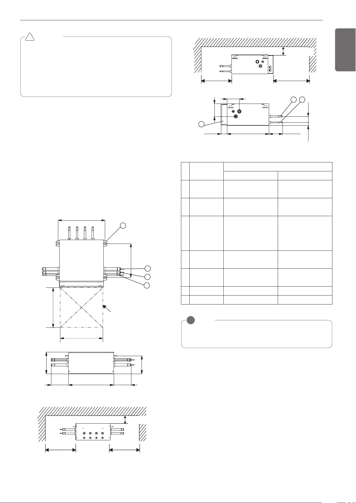
Select installation location of the HR unit suitable for following condi-
tions
- Avoid a place where rain may enter since the HR unit is for indoor.
- Sufficient service space must be obtained.
- Refrigerant pipe must not exceed limited length.
- Avoid a place subject to a strong radiation heat from other heat
source.
- Avoid a place where oil spattering, vapor spray or high frequency
electric noise is expected.
- Install the unit at a place in which it is not affected by operation noise.
(Installation within cell such as meeting room etc. may disturb busi-
ness due to noise.)
- Place where refrigerant piping, drain piping and electrical wiring
works are easy.
Inspection door
(servicing space)
481(18-15/16)
345(13-19/32)
300(11-13/16)
more
300(11-13/16)
more
(Servicing space) (Servicing space)
1
2
3
7
453(17-27/32)
174(6-27/32)
174(6-27/32)
218(8-19/32)
182(7-5/32)
450(17-23/32)
450(17-23/32)
100(3-15/16) more
(Serviceing space)
300(11-13/16)
more
450(17-23/32)
more
(Servicing space)
(Servicing space)
54
6
419(16-1/2)
61(2-13/32)
137(5-13/32)
124(4-7/8)
128(5-1/32)
30(1-3/16)
100(3-15/16) more
(Serviceing space)
60(2-3/8)
NOTE
!
• Be sure to install the inspection door at the control box side.
• If reducers are used, servicing space must be increased equal to
reducer's dimension.
(unit: mm(inch))
No. Part Name
Description
PRHR031A/PRHR041A PRHR021A
1
Low pressure
Gas pipe con-
nection port
Ø28.58(1-1/8) Brazing con-
nection
Ø22.2(7/8) Brazing connec-
tion
2
High pressure
Gas pipe con-
nection port
Ø22.2(7/8) Brazing connec-
tion
Ø19.05(3/4) Brazing con-
nection
3
Liquid pipe con-
nection port
Ø15.88(5/8) Brazing con-
nection (PRHR041A)
Ø12.7(1/2) Brazing connec-
tion (PRHR031A)
Ø9.52(3/8) Brazing connec-
tion
4
Indoor unit Gas
pipe connection
port
Ø15.88(5/8) Brazing con-
nection
Ø15.88(5/8) Brazing con-
nection
5
Indoor unit Liq-
uid pipe connec-
tion port
Ø9.52(3/8) Brazing connec-
tion
Ø9.52(3/8) Brazing connec-
tion
6
Control box - -
7
Hanger metal M10 or M8 M10 or M8
8
ENGLISH
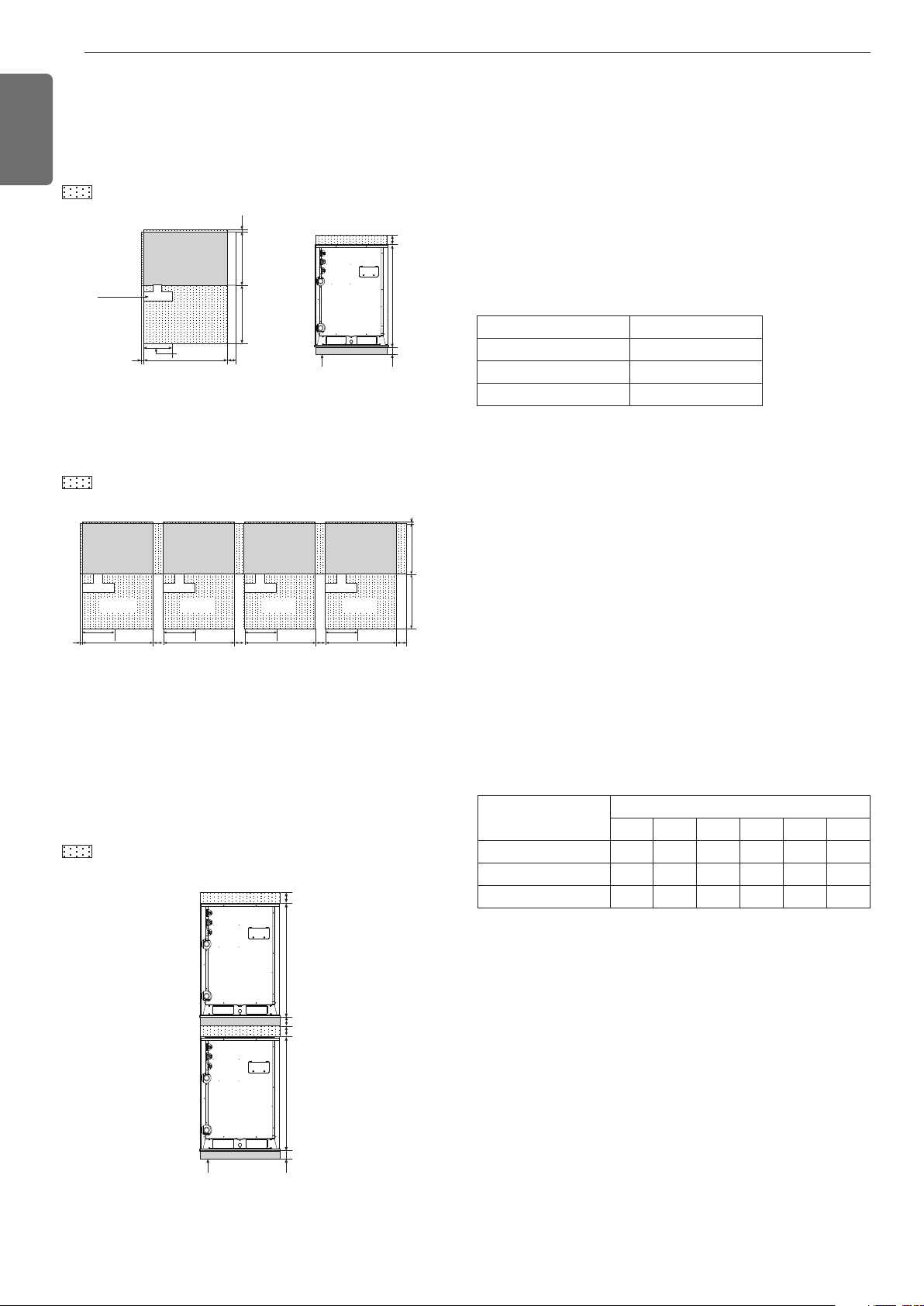
Individual Installation Water control
Collective / Continuous Installation
During the installation of the unit, consider service, inlet, and outlet
acquire the minimum space as shown in the figures below.
: Service area
* In case of the water pipe passing side product, please make suffi-
cient service place to avoid occurring between water pipe and prod-
uct side.
Space required for collective installation and continuous installation as
shown below considering passage for air and people.
: Service area
Two Layer Installation
Space required for two layer installation as shown below considering
passage for air and people.
: Service area
• Keep the water temperature between 10~45°C(50~113°F). Other it
may cause the breakdown.
- Standard water supply temperature is 30°C(86°F) for Cooling and
20°C(68°F) for heating.
• Properly control the water velocity. Otherwise it may cause the
noise, pipe vibration or pipe contraction, expansion according to the
temperature. Use the same water pipe size connected with the prod-
uct or more.
• Refer to the water source pipe diameter and water velocity table
below. As the water velocity is fast, air bubble will increase.
• Be careful of the water purity control. Otherwise it may cause the
breakdown due to water pipe corrosion.
(Refer to 'Standard Table for Water Purity Control')
• In case the water temperature is above 40°C(104°F), it is good to pre-
vent the corrosion by adding the anticorrosive agent.
• Install the pipe, valve and gauge sensor in the space where it is easy
to maintain. Install the water valve in the low position for drain, if re-
quired.
• Be careful not to let air in. If so, the water velocity will be unstable in
the circulation, pump efficiency will also decrease and may cause the
piping vibration. Therefore, install the air purge where it may gener-
ate the air.
• Choose the following anti freezing methods. Otherwise, it will be
dangerous for the pipe to break in the winter.
- Circulate the water with the pump before dropping the tempera-
ture.
- Keep the normal temperature by boiler.
- When the cooling tower is not operated for a long time, drain the
water in the cooling tower.
- Use an anti-freeze. (For using an anti freeze, change the DIP switch
on main PCB in outside unit.)
- Refer to the additive amount about freezing temperature as in the
table given below.
• In addition to anti freeze, it may cause the change of the pressure in
the water system and the low performance of the product.
• Make sure to use the closed cooling type tower.
When applying the open type cooling tower, use a 2nd heat ex-
changer to make the water supply system a closed type system.
20(25/32)
100(3-15/16)
350(13-25/32)
755(29-23/32)
600(23-5/8) 500(19-11/16)
20
(25/32)
100(3-15/16) 100(3-15/16)
997(39-1/4)
(Unit: mm(inch))
H-Beam Support
Water pipe
installation
space
Product
(Outside unit)
Service area
Service area
(Front)
(Front)
Service area
(Front)
<Front View><Top View>
<Top view>
(Unit: mm(inch))
100(3-15/16)
350(13-25/32)
755(29-23/32)
600(23-5/8) 500(19-11/16)
20
(25/32)
100(3-15/16)
350(13-25/32)
755(29-23/32)
20
(25/32)
100(3-15/16)
350(13-25/32)
755(29-23/32)
100(3-15/16)
350(13-25/32)
755(29-23/32)
Product
(Outside unit)
Service area
(Front)
Product
(Outside unit)
Service area
(Front)
Product
(Outside unit)
Service area
(Front)
Product
(Outside unit)
Service area
(Front)
H-Beam Support
<Front View>
(Unit: mm(inch))
997(39-1/4)
997(39-1/4)
100(3-15/16)
100(3-15/16)
100(3-15/16)
100(3-15/16)
Standard table for water purity control
The water may contain many foreign substances and hence may influ-
ence the performance and lifetime of the product due to the corrosion
of the condenser and water pipe. (Use water source that complies
with the below standard table for water purity control.)
If you use water supply other than the tap water to supply the water
for the cooling tower, you must do a water quality inspection.
• If you use the closed cooling tower, the water quality must be con-
trolled in accordance with the following standard table.
If you do not control the water quality in accordance with the follow-
ing standard water quality table, it can cause performance deteriora-
tion to the air conditioner and severe problem to the product
WATER CONTROL INSTALLATION SPACE
Anti freeze type
Minimum temperature for anti freezing [°C(°F)]
0 -5(23) -10(14) -15(5) -20(-4) -25(-13)
Ethylene glycol (%) 0 12 20 30 - -
Propylene glycol (%) 0 17 25 33 - -
Methanol (%) 0 6 12 16 24 30
Diameter [mm(inch)] Velocity range (m/s)
< 50(1-31/32) 0.6 ~ 1.2
50(1-31/32) ~ 100(5-7/8) 1.2 ~ 2.1
100100(5-7/8) < 2.1 ~ 2.7
9
ENGLISH
Items
pH(25C)
Conductivity[25C](mS/m)
Chlorine ion(mg CI
-
/l)
Sulfuric acid ion(mg SO
2
-
/l)
Acid demand[pH 4.8] (mg SiO
2/l)
Total hardness(mg SiO
2/l)
Ca hardness(mg CaCO
3/l)
Ion silica(mg SiO
2/l)
Fe(mg Fe/l)
Copper(mg Cu/l)
Sulfuric acid ion(mg S
2
/l)
Ammonium ion(mg NH
4/l)
Residual chlorine(mg Cl/l)
Free carbon dioxide(mg CO
2/l)
Stability index
7.0~8.0
Below 30
Below 50
Below 50
Below 50
Below 70
Below 50
Below 30
Below 1.0
Below 1.0
Must not be detected
Below 0.3
Below 0.25
Below 0.4
-
Below 0.3
Below 0.1
Must not be detected
Below 0.1
Below 0.3
Below 4.0
-
7.0~8.0
Below 30
Below 50
Below 50
Below 50
Below 70
Below 50
Below 30
O
O
O
O
-
-
-
-
O
O
O
O
O
O
O
O
-
-
-
-
-
O
O
O
-
O
O
O
O
O
Closed type
Basic Item
Reference Item
Effect
Circulating water Supplemented water Corrosion Scale
4
+
Reference
• The "O" mark for corrosion and scale means that there is possi-
bility of occurrence.
• When the water temperature is 40°C(104°F) or above or when
uncoated iron is exposed to the water, it can result in corrosion.
Therefore adding anti-corrosion agent or removing the air can be
very effective.
• In case of using the closed type cooling tower, the cooling water
and supplementing water must satisfy the water quality criteria
of closed type system in the table.
• Supplementing water and supplied water must be supplied with
tap water, industrial water and underground water excluding fil-
tered water, neutral water, soft water etc.
• 15 items in the table are general causes of corrosion and scale.
Sub line
40° or less
Rope supporter
A
B
The location of the Anchor bolts
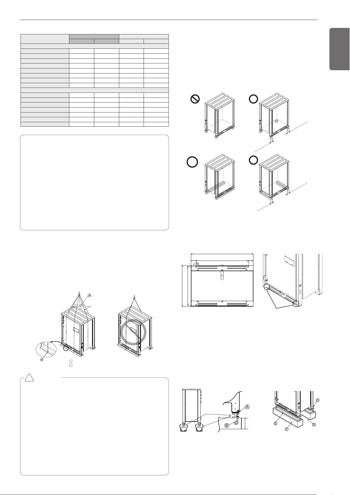
• Install at places where it can endure the weight and vibration/noise
of the outside unit .
• The outside unit supports at the bottom shall have width of at least
100mm(3-15/16inch) under the Unit’s legs before being fixed.
• The outside unit supports should have minimum height of 200mm
(7-7/8inch).
• Anchor bolts must be inserted at least 75mm(2-15/16 inch).
At least 100mm
(3-15/16 inch)
At least 100mm
(3-15/16 inch)
At least 100mm
(3-15/16 inch)
At least 100mm
(3-15/16 inch)
The location of
anchor bolt
500
62(2-7/16)
62(2-7/16)
631(24-27/32)
755(29-23/32)
Unit: mm(inch)
500(19-11/16)
472(18-37/64)
Foundation for Installation
• Fix the unit tightly with bolts as shown below so that unit will not fall
down due to earthquake or gust.
• Use the H-beam support as a base support
• Noise and vibration may occur from the floor or wall since vibration is
transferred through the installation part depending on installation sta-
tus. Thus, use anti-vibration materials (cushion pad) fully (The base
pad shall be more than 200mm(7-7/8inch)).
At least
200mm
(7-7/8inch)
INSTALLATION
LIFTING METHOD
- When carrying the unit suspended, pass the ropes under the unit and
use the two suspension points each at the front and rear.
- Always lift the unit with ropes attached at fours points so that impact
is not applied to the unit.
- Attach the ropes to the unit at an angle of 40° or less
CAUTION
Be very careful while carrying the product.
• Do not have only one person carry product if it is more than 20
kg(44lbs).
• PP bands are used to pack some products. Do not use them as a
mean for transportation because they are dangerous.
• Tear plastic packaging bag and scrap it so that children cannot
play with it. Otherwise plastic packaging bag may suffocate chil-
dren to death.
• When carrying in Outdoor Unit, be sure to support it at four
points. Carrying in and lifting with 3-point support may make Out-
door Unit unstable, resulting in a fall.
• Use 2 belts of at least 8m(26.2ft) long.
• Place extra cloth or boards in the locations where the casing
comes in contact with the sling to prevent damage.
• Hoist the unit making sure it is being lifted at its center of gravity.
!
10
ENGLISH
Unit: mm(inch)
200(7-7/8)
75(2-61/64)
75(2-61/64)
200(7-7/8)
100(3-15/16)
Ⓐ The corner part must be fixed firmly. Otherwise, the support for the
installation may be bent.
Ⓑ Get and use M10 Anchor bolt.
Ⓒ Put Cushion Pad between the outside unit and ground support for
the vibration protection in wide area.
Ⓓ Space for pipes and wiring (Pipes and wirings for bottom side)
Ⓔ H-beam support
Ⓕ Concrete support
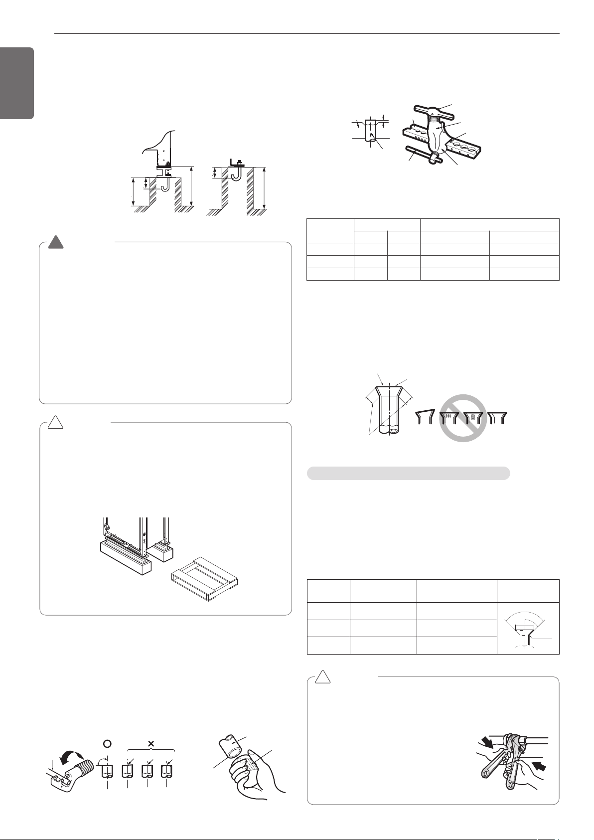
CAUTION
• Be sure to remove the Pallet(Wood Support) of the bottom
side of the outside unit Base Pan before fixing the bolt. It
may cause the unstable state of the outdoor settlement,
and may cause freezing of the heat exchanger resulting in
abnormal operations.
• Be sure to remove the Pallet(Wood Support) of the bottom
side of the outside unit before welding. Not removing Pal-
let(Wood Support) causes hazard of fire during welding.
WARNING
• Install where it can sufficiently support the weight of the out-
side unit .
If the support strength is not enough, the outside unit may
drop and hurt people.
• Install where the outside unit may not fall in strong wind or
earthquake.
If there is a fault in the supporting conditions, the outside unit
may fall and hurt people.
• Please take extra cautions on the supporting strength of the
ground, water outlet treatment(treatment of the water flowing
out of the outside unit in operation), and the passages of the
pipe and wiring, when making the ground support.
• Do not use tube or pipe for water outlet in the Base pan. Use
drainage instead for water outlet. The tube or pipe may freeze
and the water may not be drained.
Pallet(Wood Support)
- Remove before Installation
!
!
Main cause of gas leakage is defect in flaring work. Carry out correct
flaring work in the following procedure.
Cut the pipes and the cable
- Use the accessory piping kit or the pipes purchased locally.
- Measure the distance between the indoor and the outside unit .
- Cut the pipes a little longer than measured distance.
- Cut the cable 1.5m(4.92ft) longer than the pipe length.
Pipe
Reamer
Point down
Copper
tube
90
Slanted Uneven Rough
Preparation of Piping
Burrs removal
- Completely remove all burrs from the cut cross section of pipe/tube.
- Put the end of the copper tube/pipe to downward direction as you re-
move burrs in order to avoid to let burrs drop in the tubing.
Flaring work
- Carry out flaring work using flaring tool as shown below.
Firmly hold copper tube in a bar(or die) as indicated dimension in the
table above.
Check
- Compare the flared work with figure below.
- If flare is noted to be defective, cut off the flared section and do flar-
ing work again.
Bar
Copper pipe
Clamp handle
Red arrow mark
Cone
Yoke
Handle
Bar
"A"
Inclined
Inside is shining without scratches.
Smooth all round
Even length
all round
Surface
damaged
Cracked Uneven
thickness
= Improper flaring =
Flare shape and flare nut tightening torque
Precautions when connecting pipes
- See the following table for flare part machining dimensions.
- When connecting the flare nuts, apply refrigerant oil to the inside and
outside of the flares and turn them three or four times at first. (Use
ester oil or ether oil.)
-
See the following table for tightening torque.(Applying too much torque may
cause the flares to crack.)
- After all the piping has been connected, use nitrogen to perform a
gas leak check.
CAUTION
• Always use a charge hose for service port connection.
•
After tightening the cap, check that no refrigerant leaks are present
.
• When loosening a flare nut, always use two wrenches in
combination, When connecting the piping,
always use a spanner and torque wrench
in combination to tighten the flare nut.
• When connecting a flare nut, coat the
flare(inner and outer faces) with oil for
R410A(PVE) and hand tighten the nut
3 to 4 turns as the initial tightening.
Union
!
Indoor unit
[kW(Btu/h)]
Pipe [mm(inch)] "A" [mm(inch)]
Gas Liquid Gas Liquid
<5.6 (19,100) 12.7(1/2) 6.35(1/4) 0.5~0.8 (0.02~0.03) 0~0.5 (0~0.02)
<16.0 (54,600) 15.88(5/8) 9.52(3/8) 0.8~1.0 (0.03~0.04) 0.5~0.8 (0.02~0.03)
<22.4 (76,400) 19.05(3/4) 9.52(3/8) 1.0~1.3 (0.04~0.05) 0.5~0.8 (0.02~0.03)
pipe size
[mm(inch)]
Tightening Torque
N·m(lbs ·ft)
A [mm(inch)] Flare shape
Ø9.52(3/8) 38±4(28±3.0) 12.8(0.5)~13.2(0.52)
90
2
45
2
A
R=0.4~0.8
Ø12.7(1/2) 55±6(41±4.4) 16.2(0.64)~16.6(0.65)
Ø15.88(5/8) 75±7(55±5.2) 19.3(0.76)~19.7(0.78
11
ENGLISH
Opening shutoff valve
1 Remove the cap and turn the valve counter clockwise with the
wrench.
2 Turn it until the shaft stops.
Do not apply excessive force to the shutoff valve. Doing so may
break the valve body, as the valve is not a backseat type. Always
use the special tool.
3 Make sure to tighten the cap securely.
Heat insulation
1 Use the heat insulation material for the refrigerant piping which has
an excellent heat-resistance (over 248°F).
2 Precautions in high humidity circumstance:
This air conditioner has been tested according to the "ISO Condi-
tions with Mist" and confirmed that there is not any default. How-
ever, if it is operated for a long time in high humid atmosphere
(dew point temperature: more than 73.4°F), water drops are liable
to fall. In this case, add heat insulation material according to the fol-
lowing procedure:
- Heat insulation material to be prepared... EPDM (Ethylene Propy-
lene Diene Methylene)-over 248°F the heat-resistance tempera-
ture.
- Add the insulation over 10mm(0.39 inch) thickness at high humid-
ity environment.
Indoor unit
Thermal insulator
(accessory)
Fastening band
(accessory)
Refrigerant piping
Closing shutoff valve
1 Remove the cap and turn the valve clockwise with the wrench.
2 Securely tighten the valve until the shaft contacts the main body seal.
3 Make sure to tighten the cap securely.
* For the tightening torque, refer to the table on the below.
Tightening torque
Plumbing materials and storage methods
Pipe must be able to obtain the specified thickness and should be
used with low impurities.
Also when handling storage, pipe must be careful to prevent a frac-
ture, deformity and wound.
Should not be mixed with contaminations such as dust, moisture.
Shut off
valve size
[mm(inch)]
Tightening torque N·m(lbs ·ft)(Turn clockwise to close)
Shaft(valve body)
Cap
(Valve lid)
Service
port
Flare nut
Gas line pip-
ing attached
to unit
Closed Opened
Hexagonal
wrench
Ø6.35
(1/4)
6.0 ±0.6
(4.4±0.4)
5.0 ±0.0
(3.7±0.4)
4mm
(0.16inch)
17.6±2.0
(13.0±1.5)
12.7±2
(9.4±1.5)
16±2
(12±1.5)
-
Ø9.52
(3/8)
38±4
(28±3.0)
Ø12.7
(1/2)
10.0 ±1.0
(7.4±0.7)
20.0±2.0
(14.8±1.5)
55±6(
41±4.4)
Ø15.88
(5/8)
12.0 ±1.2
(8.9±0.9)
5mm
(0.24inch)
25.0±2.5
(18.4±1.8)
75±7
(55±5.1)
Ø19.05
(3/4)
14.0 ±1.4
(10.3±1.0)
110±10
(81.1±7.4)
Ø22.2
(7/8)
30.0 ±3.0
(22.1±2.2)
8mm
(0.31inch)
-
25±3.0
(18.5±2.2)
Ø25.4
(1.0)
Refrigerant piping on three principles
Drying Cleanliness Airtight
Should be no moisture
inside
No dust inside.
There is no refrigerant
leakage
Items
Moisture
Dust
Leakage
Cause
failure
- Significant hydroly-
sis of refrigerant oil
- Degradation of re-
frigerant oil
- Poor insula’tion of
the compressor
- Do not cold and
warm
- Clogging of EEV,
Capillary
- Degradation of re-
frigerant oil
- Poor insulation of
the compressor
- Do not cold and
warm
- Clogging of EEV,
Capillary
- Gas shortages
- Degradation of re-
frigerant oil
- Poor insulation of
the compressor
- Do not cold and
warm
Coun-
termea-
sure
-
No moisture in the pipe
- Until the connec-
tion is completed,
the plumbing pipe
entrance should be
strictly controlled.
- Stop plumbing at
rainy day.
- Pipe entrance
should be taken
side or bottom.
-
When removal burr
after cutting pipe, pipe
entrance should be
taken down.
- Pipe entrance
should be fitted cap
when pass through
the walls.
- No dust in the pipe.
- Until the connec-
tion is completed,
the plumbing pipe
entrance should be
strictly controlled.
- Pipe entrance
should be taken
side or bottom.
- When removal burr
after cutting pipe,
pipe entrance
should be taken
down.
- Pipe entrance
should be fitted cap
when pass through
the walls.
- Airtightness test
should be.
- Brazing operations
to comply with
standards.
- Flare to comply
with standards.
- Flange connections
to comply with
standards.
Nitrogen substitution method
Welding, as when heating without nitrogen substitution a large
amount of the oxide film is formed on the internal piping.
The oxide film is a caused by clogging EEV, Capillary, oil hole of accu-
mulator and suction hole of oil pump in compressor.
It prevents normal operation of the compressor.
In order to avoid this problem, Welding should be done after replacing
air by nitrogen gas.
When welding plumbing pipe, the work is required.
Regulator
Nitrogen gas Pressure
0.02Mpa (2.9psi) less
Auxiliary valve
Taping
(Should not
contain air)
Welding Point
Note) should not block the outlet side.
When the internal pressure in pipe is abo
ve the atmospheric pressure, pinhole is o
ccurred and it is a leakage cause.
Oxide scale
Nitrogen
12
ENGLISH
1
Always use the nitrogen.(not use oxygen, carbon dioxide, and a
Chevron gas): Please use the following nitrogen pressure
0.02Mpa (2.9psi) Oxygen – Promotes oxidative degradation of re-
frigerant oil. Because it is flammable, it is strictly prohibited to
use Carbon dioxide – Degrade the drying characteristics of gas
Chevron Gas – Toxic gas occurs when exposed to direct flame.
2 Always use a pressure reducing valve.
3 Please do not use commercially available antioxidant.
The residual material seems to be the oxide scale is ob-
served. In fact, due to the organic acids generated by oxida-
tion of the alcohol contained in the anti-oxidants, ants nest
corrosion occurs. (causes of organic acid
→
alcohol + copper
+ water + temperature)
CAUTION
!
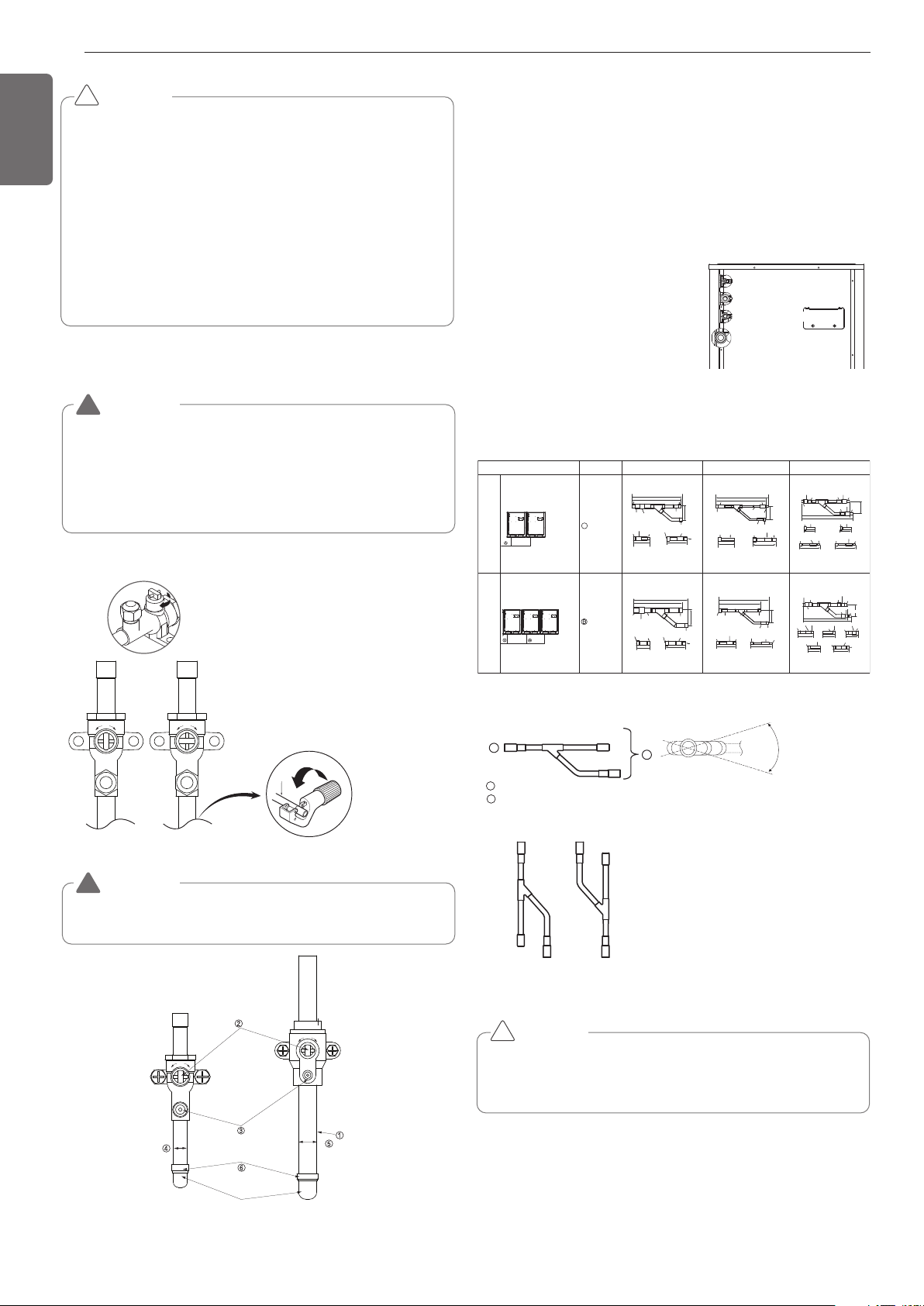
Cautions in pipe connection/valve operation
WARNING
After completing work, securely tighten both service ports and
caps so that gas does not leak.
!
WARNING
Always use extreme care to prevent the refrigerant gas (R410A)
from leakage while using fire or flame. If the refrigerant gas
comes in contact with the flame from any source, such as a gas
stove, it breaks down and generates a poisonous gas which can
cause gas poisoning. Never perform brazing in an unventilated
room. Always conduct an inspection for gas leakage after installa-
tion of the refrigerant piping has been completed.
!
Open status when both the pipe and the valve are
in a straight line.
Cut both the pipe and the valve with a cutter to
suit the length
[Don't cut the length of less than 70mm(2-3/4”)]
CLOSE OPEN
❈ Remove the front panel before pipe
connection
❈ Must check the pipe (liquid pipe, low
pressure gas pipe, high pressure gas
pipe) before pipe connection
① Pipe joint (auxiliary parts): Securely perform brazing with a nitrogen
blow into the service port.(Releasing pressure : 0.02 MPa(2.9psi) or
less)
② Cap: Remove caps and operate valve, etc. After operation, always
reattach caps (tightening torque of valve cap: 25Nm (250kg-cm) or
more). (Don't remove the internal part of the port)
③ Service port: Make the refrigerant pipe vacuum and charge it using
the service port. Always reattach caps after completing work (tight-
ening torque of service cap: 14Nm (140kg-cm) or more).
④ Liquid pipe
⑤ Gas pipe
⑥ Elbow joint (field supply)
Elbow
Ball Valve(Gas Pipe)
Ball Valve
(Liquid Pipe)
Liquid pipe
Gas pipe
Liquid pipe
Gas pipe
Liquid pipe
Low pressure gas pipe
High pressure gas pipe
Connection of Outside units
AB
ABC
(Master) (Slave1)
(Master) (Slave1) (Slave2)
2 Unit
3 Unit
ARCNN21
ARCNN31
A
Outside units Model
Low Pressure Gas Pipe
Liquid Pipe
High Pressure Gas Pipe
O.D25.4(1)
I.D22.2(7/8)
I.D19.05(3/4)
120(4-23/32)
X2
O.D19.05(3/4)
I.D15.88(5/8)
I.D12.7(1/2)
110(4-11/32)
O.D25.4(1)
I.D22.2(7/8)
80(3-5/32)
O.D12.7(1/2)
I.D9.52(3/8)
70(2-3/4)
453(17-27/32)
491(19-9/32)
111
(4-3/8)
I.D28.58(1-1/8)
I.D34.9(1-3/8)
I.D28.58(1-1/8)
I.D31.8(1-1/4)
I.D25.4(1)
I.D31.8(1-1/4)
I.D25.4(1)
I.D28.58(1-1/8)
I.D31.8(1-1/4)
130(5-1/8)
416(16-3/8)
408(16-1/16)
111(4-3/8)
I.D.38.1(1-1/2)
I.D.34.9(1-3/8)
O.D.34.9(1-3/8)
I.D.41.3(1-5/8)
I.D.31.8(1-1/4)
I.D.28.58(1-1/8)
I.D.28.58(1-1/8)
I.D.28.58(1-1/8)
I.D.22.2(7/8)
331(13-1/32)
314(12-3/8)
O.D.19.05(3/4)
I.D.19.05(3/4)
I.D.15.88(5/8)
I.D.15.88(5/8)
I.D.15.88(5/8)
I.D.22.2(7/8)
I.D.12.7(1/2)
I.D.12.7(1/2)
I.D.9.52(3/8)
70(2-3/4)
83(3-9/32)
O.D.19.05(3/4)
O.D.19.05(3/4)
I.D.15.88(5/8)
I.D.22.2(7/8)
I.D.12.7(1/2)
334(13-5/32)
281(11-1/16)
83(3-9/32)
I.D.34.9(1-3/8)
O.D.34.9(1-3/8)
125(4-29/32)
406(16)
353(13-29/32)
111(4-3/8)
I.D34.9(1-1/8)
I.D.28.58(1-1/8)
I.D.41.3(1-5/8)
I.D38.1(1-1/2)
I.D.41.3(1-5/8)
471(18-17/32)
517(20-11/32)
125(4-29/32)
I.D41.3(1-5/8)
I.D38.1(1-1/2)
I.D38.1(1-1/2)
I.D34.9(1-3/8)
I.D34.9(1-3/8)
I.D34.9(1-3/8)
I.D28.58(1-1/8)
I.D19.05
(3/4)
I.D22.2(7/8)
O.D28.58(1-1/8)
120(4-23/32)
I.D19.05
(3/4)
I.D22.2(7/8)
O.D28.58(1-1/8)
120(4-23/32)
O.D15.88(5/8) I.D9.52(3/8)
I.D12.7(1/2)
110(4-11/32)
O.D12.7(1/2)
I.D6.35(1/4)
I.D9.52(3/8)
110(4-11/32)
O.D.19.05(3/4)
I.D.12.7(1/2)
I.D.15.88(5/8)
X2
110(4-11/32)
130(5-1/8)
I.D12.7(1/2)
I.D19.05
(3/4)
I.D22.2(7/8)
I.D41.3(1-5/8)
I.D38.1(1-1/2)
I.D41.3(1-5/8)
O.D34.9(1-3/8)
O.D38.1(1-1/2)
O.D28.58(1-1/8)
O.D15.88(5/8)
90(3-17/32)
70(2-3/4)
120(4-23/32)
120(4-23/32)
I.D19.05(3/4)
I.D15.88(5/8)
O.D22.2(7/8)
I.D28.58(1-1/8)
I.D22.2(7/8)
* Install the branch pipe between outside units so that the outlet pipe
is parallel to the surface.
Y branch
A
B
To outside unit
To branch piping or indoor unit
A
B
Facing
upwards
Facing
downwards
Within ± 3° Within ± 3°
Viewed from point A
in direction of arrow
Within +/- 10
When installing the branch pipe vertically between the outside
units, the refrigerant can be uneven between the outside units,
leading to compressor burn and reduced capacity.
CAUTION
!
REFRIGERANT PIPING INSTALLATION
13
ENGLISH
Six-sided Nut
(M10 or M8)
Hanger metal
Hanger metal
Hanger metal
Flat washer
Flat washer
Flat washer
(M10)
Hanging bolt
Hanging bolt
Hanging bolt
(M10 or M8)
A
Insulation
Installation procedure for HR unit
1. Using an insert-hole-in- anchor, hang the hanging bolt.
2. Install a hexagon nut and a flat washer (locally-procured)to the hang-
ing bolt as shown in the figure in the bottom, and fit the main unit to
hang on the hanger metal.
3. After checking with a level that the unit is level, tighten the hexagon
nut.
* The tilt of the unit should be within ±5° in front/back and left/right.
4. This unit should be installed suspended from ceiling and side A
should always be
facing up.
5. Insulate not used pipes completely as shown in the figure.
Type of HR Unit
Select an HR unit according to the number of the indoor units to be in-
stalled. HR units are classified into 3 types by the number of con-
nectable indoor units.
Ex) Installation of 6 indoor units
Consists of HR unit for 4 branches and HR unit for 2 branches.
Joint Method of HR Unit (Big Duct : ARNU76GB8-,
ARNU96GB8-)
Joint Method is required when B5/B8 chassis is installed. In Joint
Method, two neighboring outlets of one HR unit are linked by Y branch
pipe and connected to one indoor unit.
Gas pipe
Gas pipe
Liquid pipe
Liquid pipe
HR Unit
1
2
3
4
High pressure Gas pipe
Liquid pipe
Low pressure
Gas pipe
Whenever connecting the indoor units with the HR unit, install the in-
door units in numerical order from No.1.
Ex) In case of installing 3 indoor units : No. 1, 2, 3 (O), No. 1, 2, 4 (X),
No.1, 3, 4 (X), No.2, 3, 4 (X).
CAUTION
!
PRHR031(3 branches)PRHR021(2 branches)
1
2
1
3
2
PRHR041(4 branches)
1
2
3
4
1
st
HR Unit 2
nd
HR Unit
1 2 3 4
B8
(96k) (28k)
BG
1 2 3 4
B8
(76k)(21k)
BH
Installation of Outside Unit, HR Unit, Indoor Unit
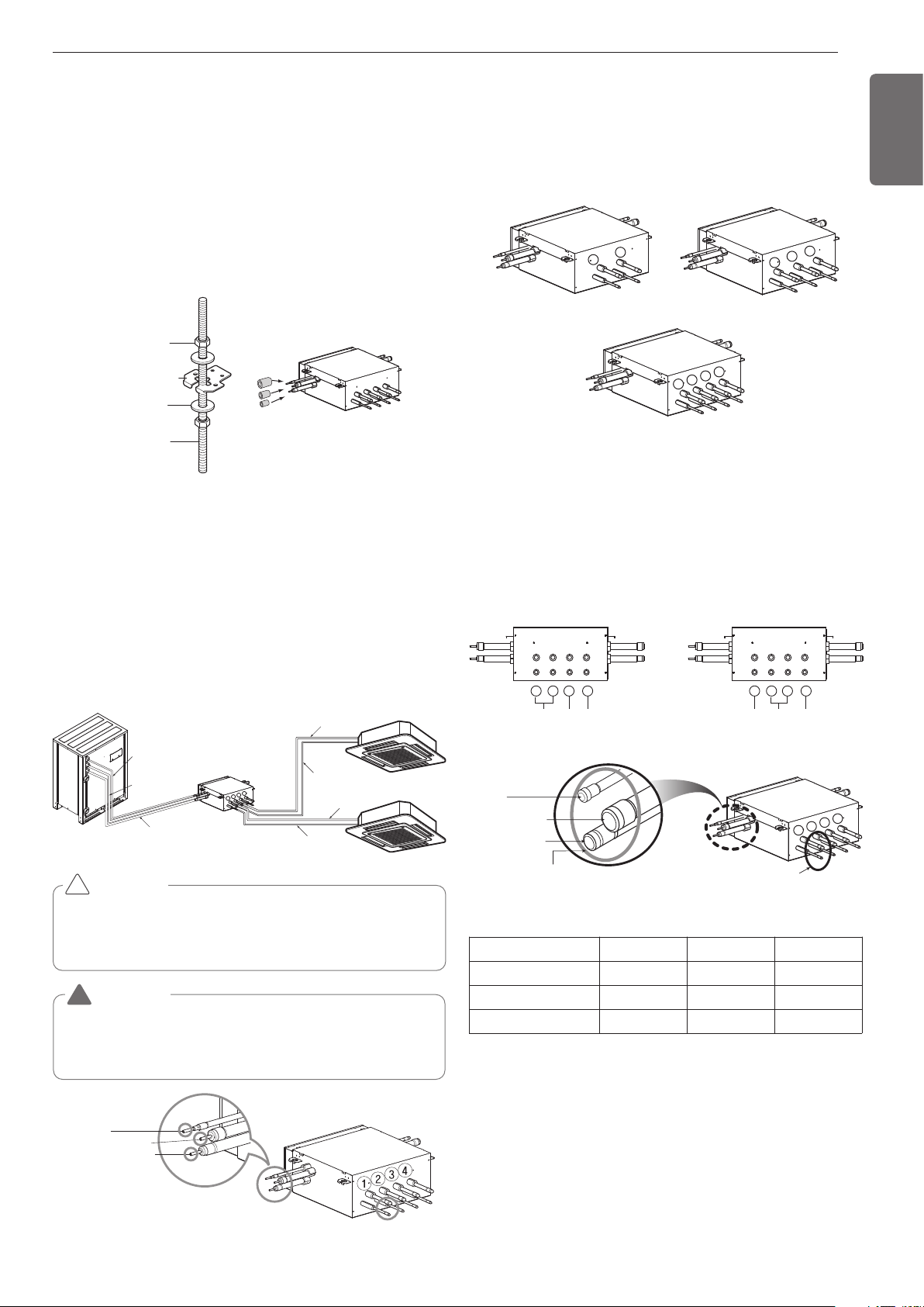
Refrigerant Pipe
3 pipes are connected to the HR unit from the outside unit, classified
into liquid pipe, low pressure gas pipe and high pressure gas pipe de-
pending on status of refrigerant passing through the pipe.
You must connect 3 pipes from outside unit to HR unit.
For connection between indoor unit and HR unit, you must connect
both liquid pipe and gas pipe from the HR unit to the indoor unit. In this
case, connect them to the indoor unit starting from No.1 connection
port of the HR unit (the port number is displayed on ports of the HR
unit). Use auxiliary flare as annexed parts in connection to the indoor
unit.
WARNING
Before brazing work, remove gas in the HR Unit by cutting the three
pipes in the small circles on the figure.
If not, it may cause injuries.
Remove the caps before connecting pipes.
!
Gas pipe Ø15.88 (5/8)
Liquid pipe Ø9.52 (3/8)
Brazing Type
Liquid pipe
Liquid pipe
Low pressure gas pipe
Low pressure gas pipe
High pressure gas pipe
High pressure gas pipe
Liquid pipe
Low pressure gas pipe
High pressure gas pipe
(Brazing Type)
Gas pipe Ø15.88 (5/8)
Liquid pipe Ø9.52 (3/8)
Brazing Type
1
2
3
4
Remove caps on
The brazing part.
Liquid pipe
Low pressure gas pipe
High pressure gas pipe
Unit : mm(inch)
HR unit PRHR021A PRHR031A PRHR041A
Low pressure gas pipe Ø22.2(7/8) Ø28.58(1-1/8) Ø28.58(1-1/8)
High pressure gas pipe Ø19.05(3/4) Ø22.2(7/8) Ø22.2(7/8)
Liquid pipe Ø9.52(3/8) Ø12.7(1/2) Ø15.88(5/8)
14
ENGLISH
HR unit HR unit
sealing
Changeover under control Auto changeover Changeover under control
Zoning control group 1 Zoning control group 2
(Max. 8 Indoor Units)
(Max. 8 Indoor Units)
WARNING
• A branch pipe of HR unit allows up to 14.5kW(48kBtu/h) based on
cooling capacity of the indoor unit. (up to 14.5kW(48kBtu/h) for
max installation)
• The maximum total capacity of indoor units connected to a
PRHR041 HR unit is 58kW(192kBtu/h).
• The maximum number of indoor units connected to a PRHR041
HR unit are 32 indoor units. (The Maximum indoor units per a
branch pipe of HR unit are 8 indoor units)
• There is not operate “Auto-changeover” & “Mode override” func-
tion in the zoning group.
• When there are operating indoor units on cooling(heating) mode,
another indoor units aren’t changed on heating(cooling) mode in
the zoning group.
!
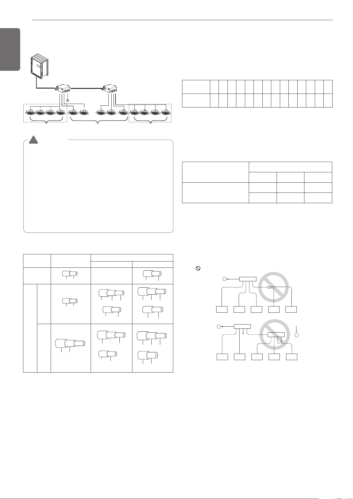
Installation of Zoning Control
Some indoor unit can be connected to one port of HR unit.
[Reducers for indoor unit and HR unit]
(Unit : mm)
Models
High pressure
–
Gas pipe
Low pressure
Liquid pipe
Indoor unit
reducer
HR unit
reducer
PRHR021A
OD22.2(7/8) Ø19.05(3/4) Ø15.88(5/8)
OD15.88(5/8) Ø
12.7(1/2)
Ø6.35(1/4)OD9.52(3/8)
Ø6.35(1/4)OD9.52(3/8)
OD19.05(3/4) Ø15.88(5/8)
OD12.7(1/2) Ø9.52(3/8)
Ø12.7(1/2)
OD22.2(7/8) Ø19.05(3/4) Ø15.88(5/8)
OD15.88(5/8) Ø12.7(1/2)
PRHR031A/
PRHR041A
OD19.05(3/4) Ø15.88(5/8)
OD28.58(1-1/8) Ø22.2(7/8) Ø19.05(3/4)
OD15.88(5/8) Ø12.7(1/2) Ø9.52(3/8)
OD15.88(5/8) Ø12.7(1/2)
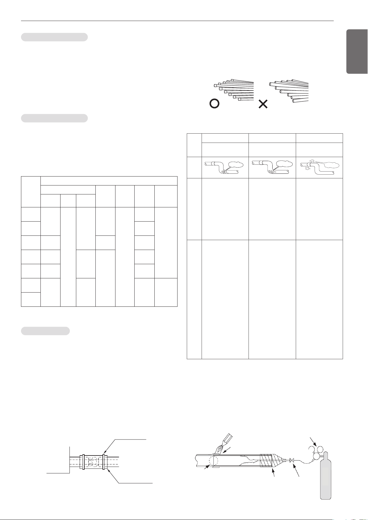
CAUTION
1 Use the following materials for refrigerant piping.
• Material: Seamless phosphorous deoxidized copper pipe
• Wall thickness : Comply with the relevant local and national regu-
lations for the designed pressure
3.8MPa(551.14psi). We recommend the follow-
ing table as the minimum wall thickness.
2 Commercially available piping often contains dust and other materi-
als. Always blow it clean with a dry inert gas.
3 Use care to prevent dust, water or other contaminants from enter-
ing the piping during installation.
4 Reduce the number of bending portions as much as possible, and
make bending radius as big as possible.
5 Always use the branch piping set shown below, which are sold sep-
arately.
Outer diameter
[mm(inch)]
6.35
(1/4)
9.52
(3/8)
12.7
(1/2)
15.88
(5/8)
19.05
(3/4)
22.2
(7/8)
25.4
(1)
28.58
(1-1/8)
31.8
(1-1/4)
34.9
(1-3/8)
38.1
(1-1/2)
41.3
(1-5/8)
44.45
(1-3/4)
53.98
(2-1/8)
Minimum thickness
[mm(inch)]
0.8
(1/32)
0.8
(1/32)
0.8
(1/32)
0.99
(5/128)
0.99
(5/128)
0.99
(5/128)
0.99
(5/128)
0.99
(5/128)
1.1
(3/64)
1.21
(3/64)
1.35
(7/128)
1.43
(7/128)
1.55
(1/16)
2.1
(11/128)
Y branch
Header
4 branch 7 branch 10 branch
ARBLB01621, ARBLB03321,
ARBLB07121, ARBLB14521,
ARBLB23220
ARBL054 ARBL057 ARBL1010
ARBL104 ARBL107 ARBL2010
6 If the diameters of the branch piping of the designated refrigerant
piping differs, use a pipe cutter to cut the connecting section and
then use an adapter for connecting different diameters to connect
the piping.
7 Always observe the restrictions on the refrigerant piping (such as
rated length, difference in height, and piping diameter).
Failure to do so can result in equipment failure or a decline in heat-
ing/cooling performance.
9 The Multi V water will stop due to an abnormality like excessive or
insufficient refrigerant. At such a time, always properly charge the
unit. When servicing, always check the notes concerning both the
piping length and the amount of additional refrigerant.
10 Never perform a pump down. This will not only damage the com-
pressor but also deteriorate the performance.
11 Never use refrigerant to perform an air purge. Always evacuate
using a vacuum pump.
12. Always insulate the piping properly. Insufficient insulation will re-
sult in a decline in heating/cooling performance, drip of condensate
and other such problems.
13. When connecting the refrigerant piping, make sure the service
valves of the Outside Unit is completely closed (the factory setting)
and do not operate it until the refrigerant piping for the Outside and
Indoor Units has been connected, a refrigerant leakage test has
been performed and the evacuation process has been completed.
Ⓐ To Outside Unit
Ⓑ Sealed Piping
8 A second branch cannot be made after a header. (These are shown
by .)
A
A
B
15
ENGLISH
CAUTION
Do not directly connect the drain outlet to the water pipe outlet.
(It can cause problems to the product.)
!
Water pipe connection
• The water pipe should be the same size of the connection on the
product or more.
• If necessary install the insulation material in the water pipe
inlet/outlet to prevent water drop, freeze and to save energy.
(Use the above 20mm(25/32inch) thickness PE insulation mate-
rial.)
• Tightly connect the socket to the water pipe refer to below table
for recommended specification.
(Too much torque may cause the damage of the facility.)
Water pipe
outlet
Gate valve
Gate valve
Service port
Pressure gauge
Temperature gauge
Service port
Strainer
Drain line
Condensed
water drain
Water pipe
Inlet
Water pipe
connection
Water pipe inlet
Water pipe outlet
mm inch (kN) (kgf) (kN) (kgf) (N
.
m) (kgf
.
m)(N
.
m) (kgf
.
m)
12.7 1/2 3.5 350 2.5 250 20 23 5 3.5
19.05 3/4 12 1200 2.5 250 20 2 115 11.5
25.4 1 11.2 1120 4 400 45 4.5 155 15.5
31.8 1 1/4 14.5 1450 6.5 650 87.5 8.75 265 26.5
38.1 1 1/2 16.5 1.7 9.5 0.95 155 16 350 35.5
50.8 2 21.5 2.2 13.5 1.4 255 26 600 61
Pipe thickness Shear stress Tensile stress
Bending
moment
Torque
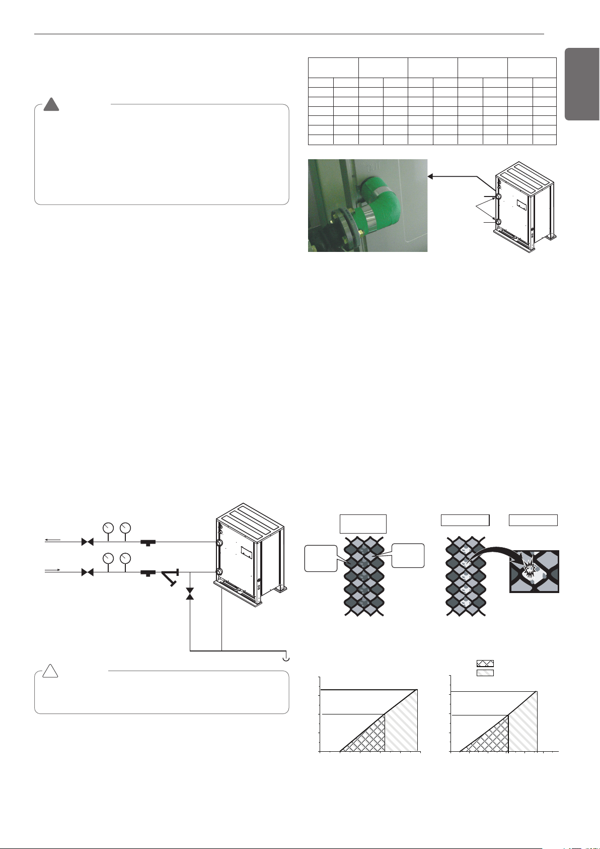
Strainer on water pipe
Upper graph is a theoretical value for selection and it may be different
according to specification of strainer.
To protect the water cooling type product, you must install a strainer
with 50 mesh or more on the heat water supply pipe.
If not installed, it can result in damage of heat exchanger by the follow-
ing situation.
1 Heat water supply within the plate type heat exchanger is com-
posed of multiple small paths.
2 If you do not use a strainer with 50 mesh or more, alien particles
can partially block the water paths.
3 When running the heater, the plate type heat exchanger plays the
role of the evaporator, and at this time, the temperature of the
coolant side drops to drop the temperature of the heat water sup-
ply, which can result in icing point in the water paths.
4 And as the heating process progresses, the water paths can be par-
tially frozen to lead to damage in plate type heat exchanger.
5 As a result of the damage of the heat exchanger from the freezing,
the coolant side and the heat water source side will be mixed to
make the product unusable.
Heat Source
Water
Refrigerant
1. Pollution of
Heat source
2. Partially frozen
3. Damage
Head loss of strainer on water pipe
96
50
45
30
15
0
0 30 60 90 120 150
0 60 120 180 240 300
60
50
45
30
15
0
60
192
g/min
kpa
kpa
g/min
: Suggestion range
: Allowed range
ARWB121DAS4 ARWB192DAS4
14. Always use a non-oxidizing brazing material for brazing the parts
and do not use flux. If not, oxidized film can cause clogging or dam-
age to the compressor unit and flux can harm the copper piping or
refrigerant oil.
INSTALLATION OF WATER PIPE
Water pipe system diagram
• The water pressure resistance of the water pipe system of this
product is 1.98MPa(287.18psi).
• When the water pipe passes indoors, make sure to execute heat
insulation on the pipe so that water drops do not form on the
outer side of the water pipe.
• The size of the drain pipe must be equal to or larger than the di-
ameter of the connecting product.
- Always install a trap so that the drained water does not back
flush.
•
Always install a strainer (50Mesh or above) at the entrance of the
water pipe. (When sand, trash, rusted pieces get mixed into the
water supply, it can cause problems to the product due to blocking)
- If On/Off valve is applied, by interlocking with outside unit, it can
save the energy consumption of pump by blocking the water
supply to the outside unit not operating. Select appropriate valve
and install on site if necessary.
• Install a pressure gauge and temperature gauge at the inlet and
outlet of the water pipe.
• Flexible joints must be installed not to cause any leakage from the
vibration of pipes.
• Install a service port to clean the heat exchanger at the each end
of the water inlet and outlet.
• For the components of the water pipe system, always use com-
ponents above the designed water pressure.
WARNING
When installing and moving the air conditioner to another site, be
sure to make recharge refrigerant after perfect evacuation.
•
If a different refrigerant or air is mixed with the original refrigerant, the
refrigerant cycle may malfunction and the unit may be damaged.
• After selecting diameter of the refrigerant pipe to suit total capac-
ity of the indoor unit connected after branching, use an appropriate
branch pipe set according to the pipe diameter of the indoor unit
and the installation pipe drawing.
!
DEVICE PROTECTION UNIT
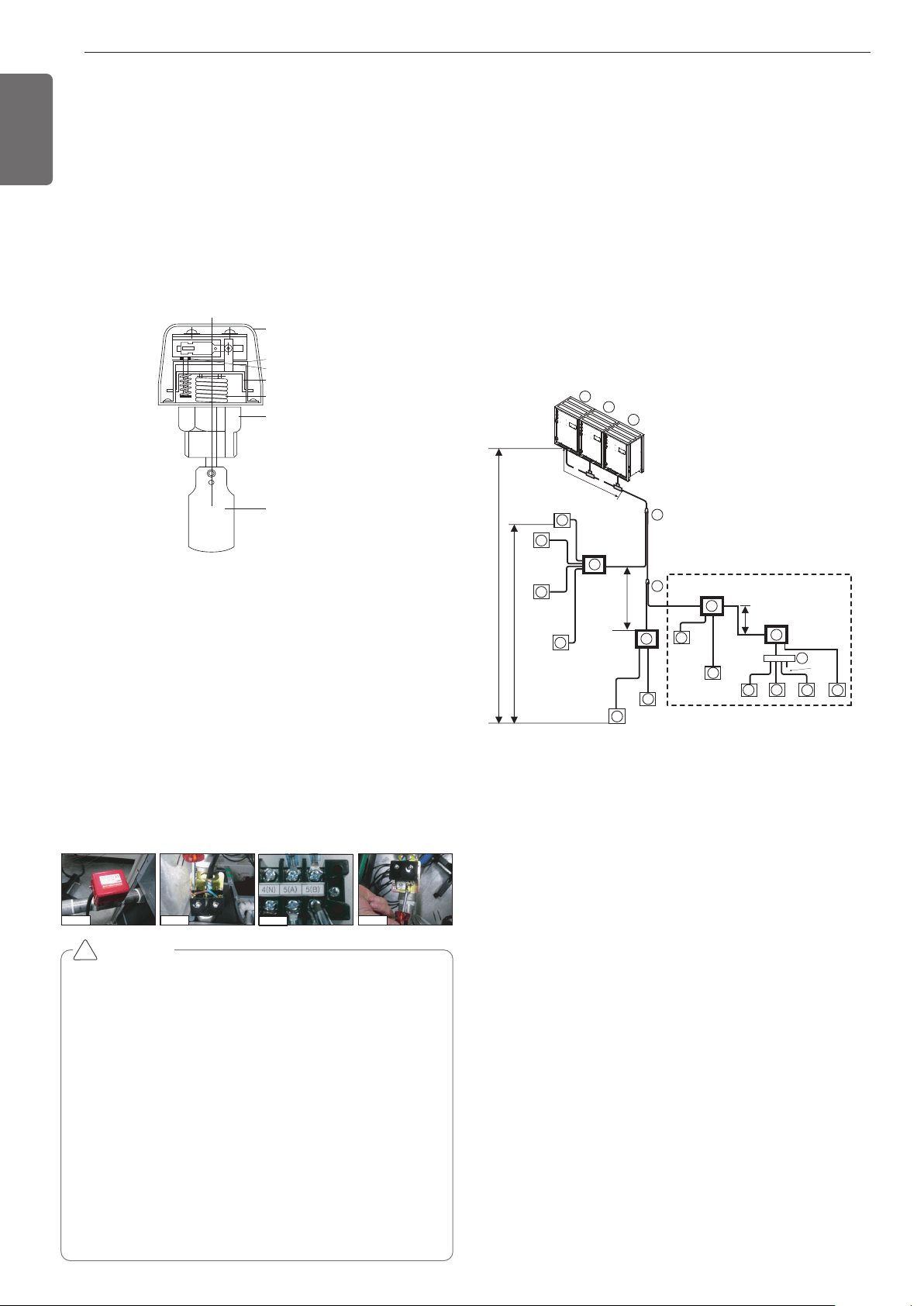
16
ENGLISH
1 inch or
3/4 inch
socket
Cover
Micro-switch
Adjustment screw
Vibration plate
Bellows
Pad
Installation of flow switch
• The flow switch must be installed at the horizontal pipe of the heat
water supply outlet of the product and check the direction of the heat
water flow before the installation. (Picture 1)
• When connecting the flow switch to the product, remove the jump
wire to connect to the communication terminal (5(A) and 5(B)) of the
outside unit control box. (Picture 2, 3) (Open the cover of the flow
switch and check the wiring diagram before connecting the wires.
The wiring method can differ by the manufacturer of the flow
switch.)
• If necessary, adjust the flow rate detection screw after consulting
with an expert and adjust to the minimum flow rate range. (Picture 4)
(Minimum flow rate range of this product is 50%. Adjust the flow
switch to touch the contact point when the flow rate reaches 50% of
the flow rate.)
- Reference flow rate : 10HP-25.4GPM, 20HP-50.7GPM)
Picture 1 Picture 2
Picture 3
Picture 4
CAUTION
• If the set value does not satisfy the minimum flow rate or if the
set value is changed by the user arbitrarily, it can result in prod-
uct performance deterioration or serious product problem.
• If the product is operated with the heat water supply not flow-
ing smoothly, it can damage the heat exchanger or cause seri-
ous product problems.
• In case of CH24 or CH180 error, there is a possibility that the
plate type heat exchanger is partially frozen inside. In this case
resolve the issue of partial freezing and then operate the prod-
uct again. (Cause of partial freezing : Insufficient heat water
flux, water not supplied, insufficient coolant, alien particle pene-
trated inside plate type heat exchanger)
• When the product operates while the flow switch touches the
contact point at the flow rate range out of the permitted range,
it can cause product performance deterioration or serious prod-
uct problem.
• Must use the normal closed type flow switch
- Circuit of outside unit is normal closed type.
!
Flow switch work
• It is recommended to install the flow switch to the water collection
pipe system connecting to the outside unit.
(Flow switch acts as the 1st protection device when the heat water
is not supplied. If a certain level of water does not flow after in-
stalling the flow switch, an error sign of CH24 error will be displayed
on the product and the product will stop operating.)
• When setting the flow switch, it is recommended to use the product
with default set value to satisfy the minimum flow rate of this prod-
uct. (The minimum flow rate range of this product is 50%. Reference
flow rate : 10HP-25.4GPM, 20HP-50.7GPM
• Select the flow switch with the permitted pressure specification con-
sidering the pressure specification of the heat water supply system.
(Control signal from outside unit is AC 220V.)
PIPE CONNECTIONS BETWEEN IN-
DOOR AND OUTSIDE UNIT
Refrigerant piping system
4 Outside Units
Example : 12 Indoor Units connected
Ⓐ : Outside Unit
Ⓑ : Y branch
Ⓓ : Indoor Unit
Ⓔ : Connection branch pipe between Outside units : ARCNB31
Ⓕ : Connection branch pipe between Outside units : ARCNB21
Ⓗ : Header
Ⓘ : HR Unit
- Case 1 ("a") : Maximum height is 15m if you install with Y branch.
- Case 2 ("b") : Maximum height is 5m in serial connection of HR units.
A1
I1
D
1
0
m
or l
ess
1
2
D
D
D
3
4
A
C1
B
C2
C3
*
B1
B2
A2
A3
a
b
c
d
e
g
j
k
x
l
m
n
sealing
f
i
H
h
"a"
"b"
E
F
I2
I4
H
I3
Master
Slave 1
Slave 2
ODU Capacity
Master ≥ Slave1 ≥ Slave 2
D
5
D
6
D
7
D
8
D
10
D
9
D
11
D
12
Conditional
To satisfy below condition to make 40m(131ft)~90m(295ft) of pipe length
after first branch.
1) Diameter of pipes between first branch and the last branch should
be increased by one step, except if the pipe diameter B,C3 is same
as Diameter A(Main pipe diameter)
Ø6.35(1/4) → Ø 9.52(3/8) → Ø 12.7(1/2) → Ø 15.88(5/8) → Ø
19.05(3/4) → Ø 22.2(7/8) →
Ø 25.4*(1), Ø 28.58(1-1/8) → Ø 31.8*(1-1/4), Ø 34.9(1-3/8) → Ø
38.1*(1-1/2)
* : If available on site, it use this size. Otherwise it can't be in-
creased.
2) While calculating total refrigerant piping length, pipe B,C3 length
should be calculated twice.
A + B x 2 + C3 x 2 + C1 + C2 + a + b + c + d + e + f + g + i + j + k
+ l + m + n ≤ 500m(1640ft)
3) Length of pipe from each indoor unit to the closest HR Unit
(a,b,c,d,e,e,g,i,j,k,l,m,n) ≤ 40m(131ft)
4) [Length of pipe from outdoor unit to the farthest indoor unit D12
(B+C3+K)]
- [Length of pipe outdoor unit to the closest indoor unit D1 (C1+a)]
≤ 40m(131ft)
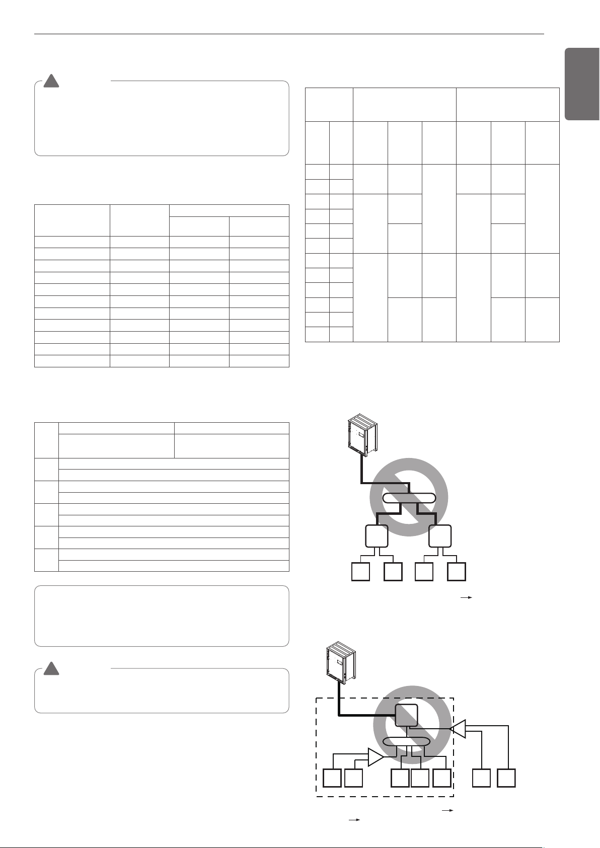
17
ENGLISH
Refrigerant pipe diameter from branch to branch (B,C,D)
WARNING
• Piping length from outside unit branch to outside unit ≤
10m(32.8ft), equivalent length : max 13m(42.7ft) (for
12Ton(144kBtu) or more)
* If the large capacity indoor units (Over 48kBtu; using over
Ø15.88(5/8)/ Ø9.52(3/8)) are installed, it should be used the Valve
Group setting.
!
Refrigerant pipe diameter from branch to branch (B,C)
Downward indoor
unit total capacity
[kW(Btu/h)]
Liquid pipe
[mm(inch)]
Gas pipe [mm(inch)]
Low pressure High pressure
≤ 5.6(19,100)
Ø6.35(1/4) Ø12.7(1/2) Ø9.52(3/8)
< 16.0 (54,600) Ø9.52(3/8) Ø15.88(5/8) Ø12.7(1/2)
≤ 22.4 (76,400)
Ø9.52(3/8) Ø19.05(3/4) Ø15.88(5/8)
< 33.6(114,700) Ø9.52(3/8) Ø22.2(7/8) Ø19.05(3/4)
< 50.4 (172,000) Ø12.7(1/2) Ø28.58(1 1/8) Ø22.2(7/8)
< 67.2 (229,400) Ø15.88(5/8) Ø28.58(1 1/8) Ø22.2(7/8)
< 72.8(248,500) Ø15.88(5/8) Ø34.9(1 3/8) Ø28.58(1 1/8)
< 100.8(344,000) Ø19.05(3/4) Ø34.9(1 3/8) Ø28.58(1 1/8)
< 173.6(592,500) Ø19.05(3/4) Ø41.3(1 5/8) Ø34.9(1 3/8)
< 184.8(630,700) Ø22.2(7/8) Ø44.5(1 3/4) Ø41.3(1 5/8)
≤ 224.0(764,400)
Ø22.2(7/8) Ø53.98(2 1/8) Ø44.5(1 3/4)
Total pipe length = A + B + C1 + C2 + C3 + a + b + c + d
+ e + f + g + i + j + k + l + m + n ≤ 500m(1640ft)
WARNING
When the equivalent length between a outside and the farthest
indoor unit is 90m(295ft) or more, main pipe(A) must be increased
one grade.
!
Refrigerant pipe diameter from outside unit to first
branch. (A)
Y branch, Header and HR unit connection pattern
* If available on site, it use this size. Otherwise it can't be increased.
Pattern 1
HR1
48k 48k
1 2
HR2
48k 48k
3 4
B
• Impossible installation : Head branch pipe HR unit
Upward out-
side unit total
capacity
Pipe diameter
Pipe diameter when pipe
length is 90m over to 1st
branch
HP TON
Liquid
mm(inch)
Low pres-
sure gas
pipe
mm(inch)
High pres-
sure gas
pipe
mm(inch)
Liquid
mm(inch)
Low pres-
sure gas
pipe
mm(inch)
High pres-
sure gas
pipe
mm(inch)
86
9.52(3/8) 22.2(7/8)
19.05(3/4)
12.7(1/2) 22.2(7/8)
19.05(3/4)
10 8
12 10
12.7(1/2)
25.4(1)
15.88(5/8)
25.4(1)
14 12
18 14
28.58(1-
1/8)
28.58
(1-1/8)
20 16
24 20
19.05(3/4)
34.9(1-
3/8)
28.58
(1-1/8)
22.2(7/8)
34.9
(1-3/8)
28.58
(1-1/8)
28 24
34 28
38 32
41.3
(1-5/8)
34.9
(1-3/8)
41.3
(1-5/8)
34.9
(1-3/8)
46 40
54 48
Pattern 2
HR1
1
234567
7k 7k 7k 7k 7k 24k 24k
• Impossible installation : HR unit Head branch
pipe Y and Head branch pipe.
B
A
• * : Assume equivalent pipe length of Y branch to be 1.64ft, that
of header to be 3.3ft, calculation purpose
• it is recommended that indoor unit is installed at lower position
than the header.
• ** : Conditional application
L
Longest pipe length *Equivalent pipe length
A+B+C3+k ≤150m(200m**)
[(492ft(656ft**)]
A+B+C3+k ≤175m(225m**)
[(574ft(738ft**)]
l
Longest pipe length after 1st branch
B+C+D+e ≤ 40m(90m**) [131ft(295ft)]
H
Difference in height (Outdoor Unit ↔ Indoor Unit)
H ≤ 50m(164ft)
h
Difference in height (Indoor Unit ↔ Indoor Unit)
h ≤ 40m(131ft)
h1
Difference in height (Outdoor Unit ↔ Outdoor Unit)
h1 ≤ 2m(6.6ft)
"a", "b"
Difference in height(HR unit ↔ HR unit)
a ≤ 15m(49ft) , b ≤ 5m(16ft)
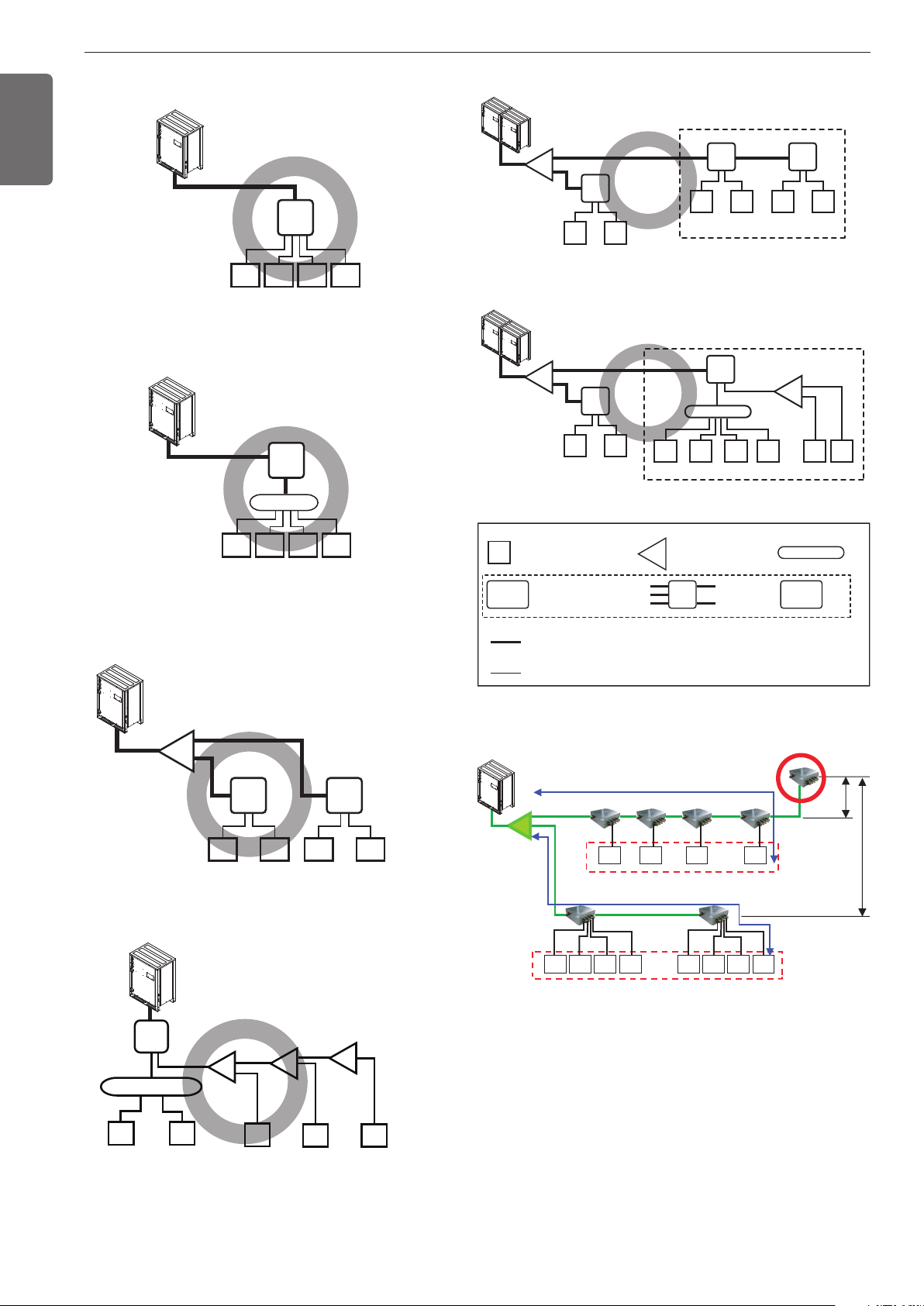
18
ENGLISH
Pattern 3
HR1
48k 48k 48k 48k
1 2 3 4
• The maximum total capacity of indoor
units is 56.4kW(192 kBtu/h).
Pattern 4
12k 12k 12k 12k
1 2 3 4
• The maximum total capacity of a branch
pipe of HR unit is 14.1kW(48 kBtu/h).
HR1
B
Pattern 5
HR1
48k 48k
A
1 2
HR2
48k 48k
3 4
HR1
24k 24k 24k
12k 12k
B
Pattern 6
A
A
A
12 345
Pattern 7
Pattern 8
HR1
A
A
A
48k 48k
1 2
• * : Serial connection of HR units : Capacity sum of indoor units ≤ 192 kBtu/h
• * : Maximum indoor units per a branch are 8 indoor units
HR2
48k 48k
3 4
HR3
48k 48k
5 6
*
HR1
48k 48k
1 2
HR2
*
B
12k 12k 12k 12k
3 4 5 6
24k
7
24k
8
• Pipe installation from outside units to HR units
: 3 pipes(Low pressure Gas pipe, High pressure Gas pipe, Liquid pipe)
• Pipe installation from HR units to indoor units
: 2 pipes(Gas pipe, Liquid pipe)
B
A
1
HR1
Outside
Unit
Indoor Unit Y Branch pipe
Low pressure Gas pipe
High pressure Gas pipe
Liquid pipe
Gas pipe
Liquid pipe
Head Branch pipe
Indoor
Unit
Keep the 40m distance from the first branch to the farthest indoor.
5m(16ft)
15m(49ft)
1) under 40m(131ft)
Keep the sum of indoor capacity under 56.4kW(192 kBtu/h).
Indoor
Unit
Indoor
Unit
Indoor
Unit
Indoor
Unit
Indoor
Unit
Indoor
Unit
Indoor
Unit
Indoor
Unit
Indoor
Unit
Indoor
Unit
Indoor
Unit
Indoor
Unit
1) under 40m(131ft)
Y branch
Keep the sum of indoor capacity under 56.4kW(192 kBtu/h).
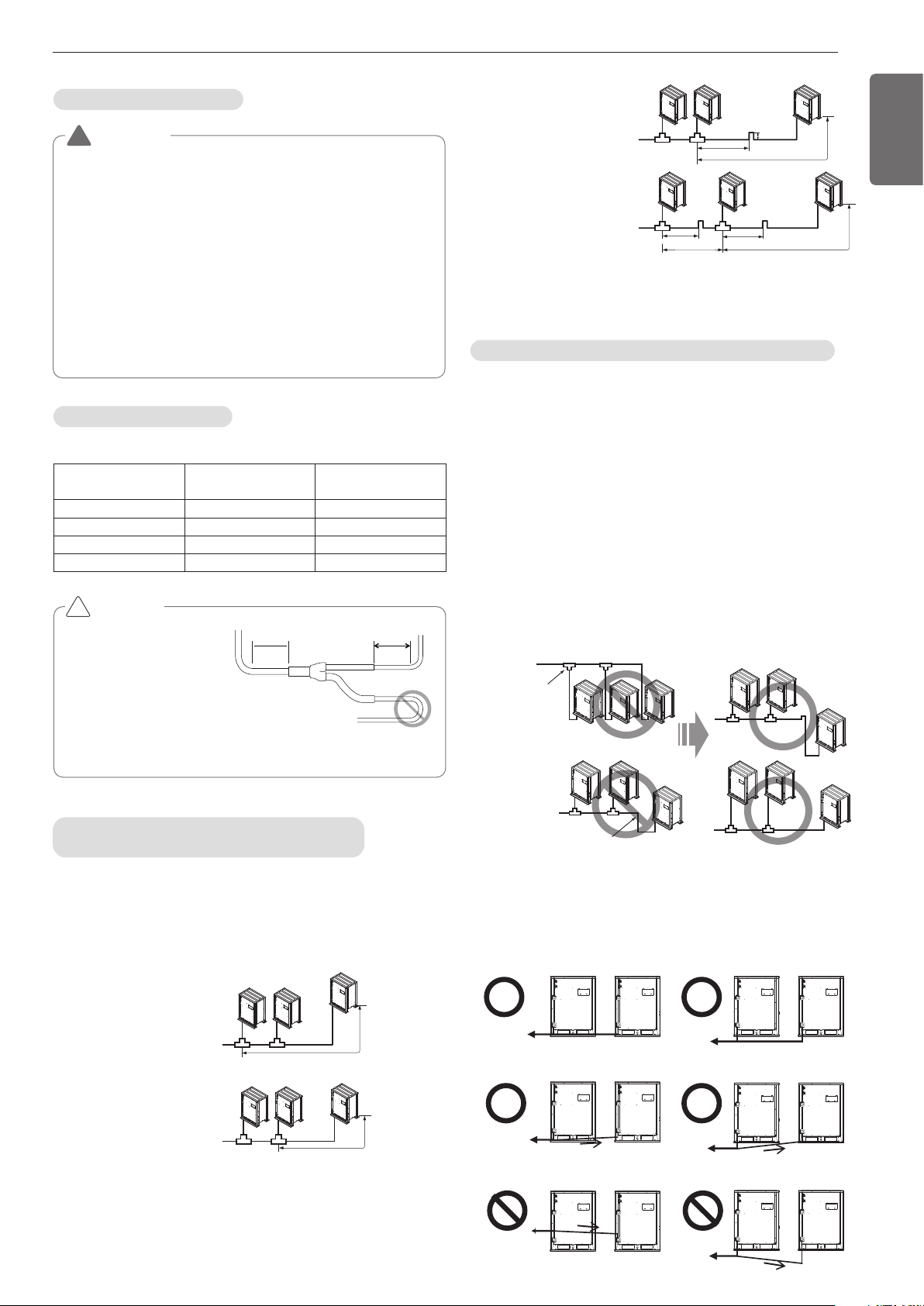
19
ENGLISH
WARNING
• In case of pipe diameter B connected after first branch is bigger than
the main pipe diameter A, B should be of the same size with A.
Ex) In case indoor unit combination ratio 120% is connected to
16Ton[20HP(58kW)] outside unit .
1) Outside unit main pipe diameter A : Ø28.58(1-1/8”)(gas pipe),
Ø12.7(1/2”)(liquid pipe)
2) Pipe diameter B after first branch according to 120% indoor
unit ombination(69.6kW) : Ø28.58 (1-1/8”)(gas pipe),
Ø15.88(5/8”) (liquid pipe)
Therefore, pipe diameter B connected after first branch would be
Ø28.58(1-1/8”) (gas pipe) / Ø12.7(1/2”)(liquid pipe) which is same with
main pipe diameter.
!
Outside unit Connection
Indoor Unit Connection
Indoor unit connecting pipe from branch (a~f)
Indoor Unit capacity
[kW(Btu/h)]
Liquid pipe
[mm(inch)]
Gas pipe
[mm(inch)]
≤ 5.6(19,100)
Ø6.35(1/4) Ø12.7(1/2)
< 16.0(54,600) Ø9.52(3/8) Ø15.88(5/8)
< 22.4(76,400) Ø9.52(3/8) Ø19.05(3/4)
< 28.0(95,900) Ø9.52(3/8) Ø22.2(7/8)
CAUTION
• Bending radius should be
at least twice the diameter
of the pipe.
• Bend pipe after
500mm(1.64ft) or more
from branch(or header).
Do not bend U type.
It may cause Performance
unsatisfactory or noise.
!
500mm(1.64ft)
or more
500mm(1.64ft)
or more
Pipe Connection Method/Precautions for
Series connections between Outside units
- Separate Y branch joints are needed for series connections between
outside unit s.
- Please refer to the below connection examples to install pipe connec-
tions between outside unit s.
- If the distance between the outside unit s becomes more than
2m(6.6ft), apply Oil Traps between the gas pipes.
- If the outside unit is located lower than the main pipe, apply Oil Trap.
Pipe connection between outside
unit s (General Case)
The maximum pipe
length after the first
branching between the
outside unit is 10m(33ft)
or less
Pipes between outside unit s
are 2m(6.6ft) or less
2m(6.6ft) or less
Pipes between outside unit
s are 2m(6.6ft) or longer
Oil Trap
Oil Trap Oil Trap
2m(6.6ft) or less
2m(6.6ft) or less
2m(6.6ft) or less
0.2m(0.66ft) or more
2m(6.6ft) or longer
2m(6.6ft) or longer
2m(6.6ft) or longer
Oil trap application method between outside units
- Because of the possibility of oil being accumulated in the outside unit
that has stopped, when there is a height difference between outside
unit pipes or if the pipe distance between the outside units is over
2m(6.6ft), you must always apply an oil trap. (But, the oil trap be-
tween outside units is limited to 1 time and is only applied to the gas
pipe.)
- If the pipe distance between the outside units is 2m(6.6ft)
or below, and if the location of the main pipe is lower than that of the
outside unit and if the location of the main pipe is lower than that of
the outside unit, the oil trap does not have to be applied.
- If the location of the main pipe is higher than the location of the out-
side unit, be careful since the oil can be accumulated in the stopped
outside unit.
- If there is high/low difference between the outside unit pipes, oil can
be accumulated to the outside unit on the lower location until the unit
stops.
- The pipes between the outside unit s must maintain horizontal level-
ness or give an inclination to prevent a back flow toward the slave
outside unit . Otherwise, the unit may not operate properly.
Examples of Wrong Pipe Connections
If the main pipe is
higher than the
outside unit, oil is
accumulated in the
outside unit.
If there are differences in the height
between the outside unit, oil is
accumulated in the lower outside unit.
Oil Trap
Toward indoor unit
Toward indoor unit
Pipe inclination
(2 or more)
Toward indoor unit
Toward indoor unit
Toward indoor unit
Toward indoor unit
(Example 1)
(Example 2)
(Example 3)
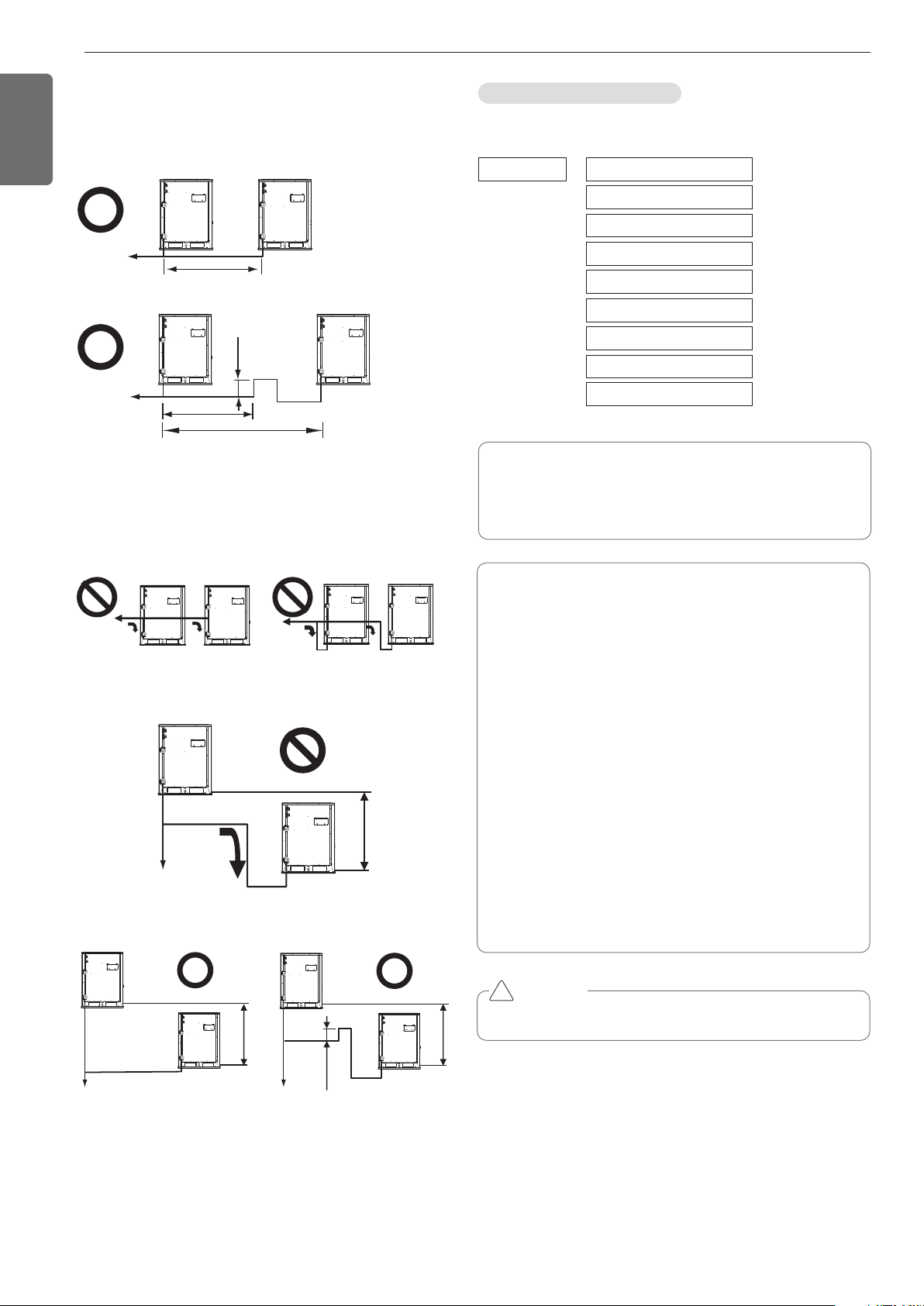
20
ENGLISH
- Apply Oil Trap as shown below when the length of the pipe between
the outside unit s is more than 2m(6.6ft). Otherwise, the unit may not
operate properly.
(Example 1)
Toward indoor unit
Toward indoor unit
2m(6.6ft)
2m(6.6ft)
2m(6.6ft)
0.2m(0.66ft)
Oil Trap
(Example 2)
- When connecting the pipes between the outside unit s, the accumu-
lation of oil in the slave outside unit should be avoided. Otherwise,
the unit may not operate properly.
(Example 1)
Toward indoor unit
Toward
indoor unit
h
Toward indoor unit
(Example 2)
h
h
0.2m(0.66ft)
Toward indoor unit Toward indoor unit
Oil Trap
(Example 3)
The amount of Refrigerant
The calculation of the additional charge should take into account the
length of pipe and CF(correction Factor) value of indoor unit.
Total liquid pipe : Ø25.4 mm (1.0 inch)
Additional charge(kg)
Total liquid pipe : Ø22.2 mm (7/8 inch)
Total liquid pipe : Ø19.05 mm (3/4 inch)
Total liquid pipe : Ø15.88 mm (5/8 inch)
Total liquid pipe : Ø12.7 mm (1/2 inch)
Total liquid pipe : Ø9.52 mm (3/8 inch)
Total liquid pipe : Ø6.35 mm (1/4 inch)
Number of installed HR units
CF value of indoor unit
=
+
+
+
+
+
+
+
x 0.480kg/m(0.323(lbs/ft))
x 0.354kg/m(0.238(lbs/ft))
x 0.266kg/m(0.179(lbs/ft))
x 0.173kg/m(0.116(lbs/ft))
x 0.118kg/m(0.079(lbs/ft))
x 0.061kg/m(0.041(lbs/ft))
x 0.022kg/m(0.015(lbs/ft))
x 5kg(1.1lbs)
Amount refrigerant of Indoor units
Example) 4Way Ceiling Cassette 14.5kW -1ea, Ceiling concealed
Duct 7.3kW-2ea,
Wall Mounted 2.3kW-4ea
CF = 0.64 × 1 + 0.26 × 2 + 0.24 × 4 = 2.12kg (4.67lbs)
Attach the additional refrigerant table of IDU.
CAUTION
Use only 2-series of indoor unit. Ex) ARNU***2/A
!
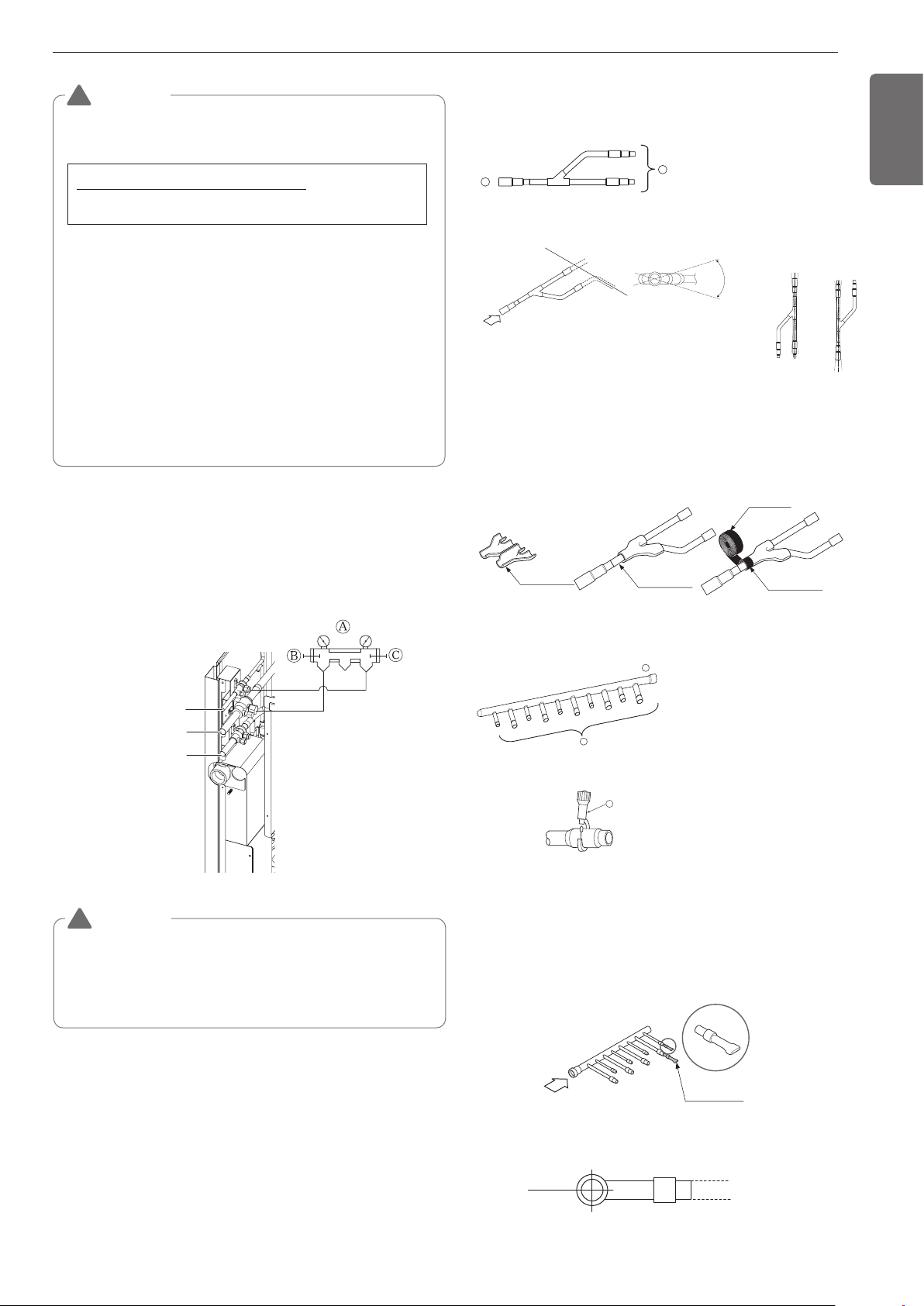
21
ENGLISH
Low Pressure Gas pipe
High Pressure Gas pipe
Liquid pipe
Ⓐ Manifold Gauge
Ⓑ Low pressure side Handle
Ⓒ High pressure side Handle
WARNING
• Pipe to be vacuumed : gas pipe, liquid pipe
• If the refrigerant amount is not exact, it may not operate
properly.
• If additionally bottled refrigerant amount is over 10%, condenser
burst or insufficient indoor unit performance may be caused.
!
Refrigerant charging
WARNING
• Regulation for refrigerant leakage
: the amount of refrigerant leakage should satisfy the following
equation for human safety.
If the above equation can not be satisfied, then follow the follow-
ing steps.
• Selection of air conditioning system: select one of the next
- Installation of effective opening part
- Reconfirmation of Outdoor Unit capacity and piping length
- Reduction of the amount of refrigerant
- Installation of 2 or more security device (alarm for gas leakage)
• Change Indoor Unit type
:
installation position should be over 2m(6.56ft) from the floor (Wall
mounted type Cassette type)
• Adoption of ventilation system
: choose ordinary ventilation system or building ventilation sys-
tem
• Limitation in piping work
: Prepare for earthquake and thermal stress
!
Volume of the room at which Indoor Unit of
the least capacity is installed
Total amount of refrigerant in the system
0.44(kg/m
3
(0.028(lbs/ft
3
))
• When the number of indoor units to be connected to the branch
pipes is less than the number of branch pipes available for connec-
tion then cap pipes should be fitted to the surplus branches.
• Fit branch pipe lie in a horizontal plane.
Pinched pipe
B
Horizontal plane
View from point B in the direction of the arrow
Y branch
Header
A
B
Facing
upwards
Facing
downwards
Within ±3° Within ±3°
Viewed from point A
in direction of arrow
Horizontal
plane
Within ±10°
A
Insulator
(included with kit)
Liquid and gas
pipe joints
Insulator for
field piping
Tape
(field supply)
A
B
C
Ⓐ To Branch Piping or Indoor Unit
Ⓑ To Outside Unit
• Ensure that the branch pipes are attached horizontally or vertically
(see the diagram below.)
• There is no limitation on the joint mounting configuration.
• If the diameter of the refrigerant piping selected by the procedures
described is different from the size of the joint, the connecting sec-
tion should be cut with a pipe cutter.
• Branch pipe should be insulated with the insulator in each kit.
Ⓐ To Outside Unit
Ⓑ To Indoor Unit
• The indoor unit having larger ca-
pacity must be installed closer
to Ⓐ than smaller one.
• If the diameter of the refrigerant
piping selected by the proce-
dures described is different
from the size of the joint, the
connecting section should be
cut with a pipe cutter.
ⓒ Pipe cutter
• When the number of pipes to be
connected is smaller than the
number of header branches, in-
stall a cap to the unconnected
branches.
Branch pipe Fitting
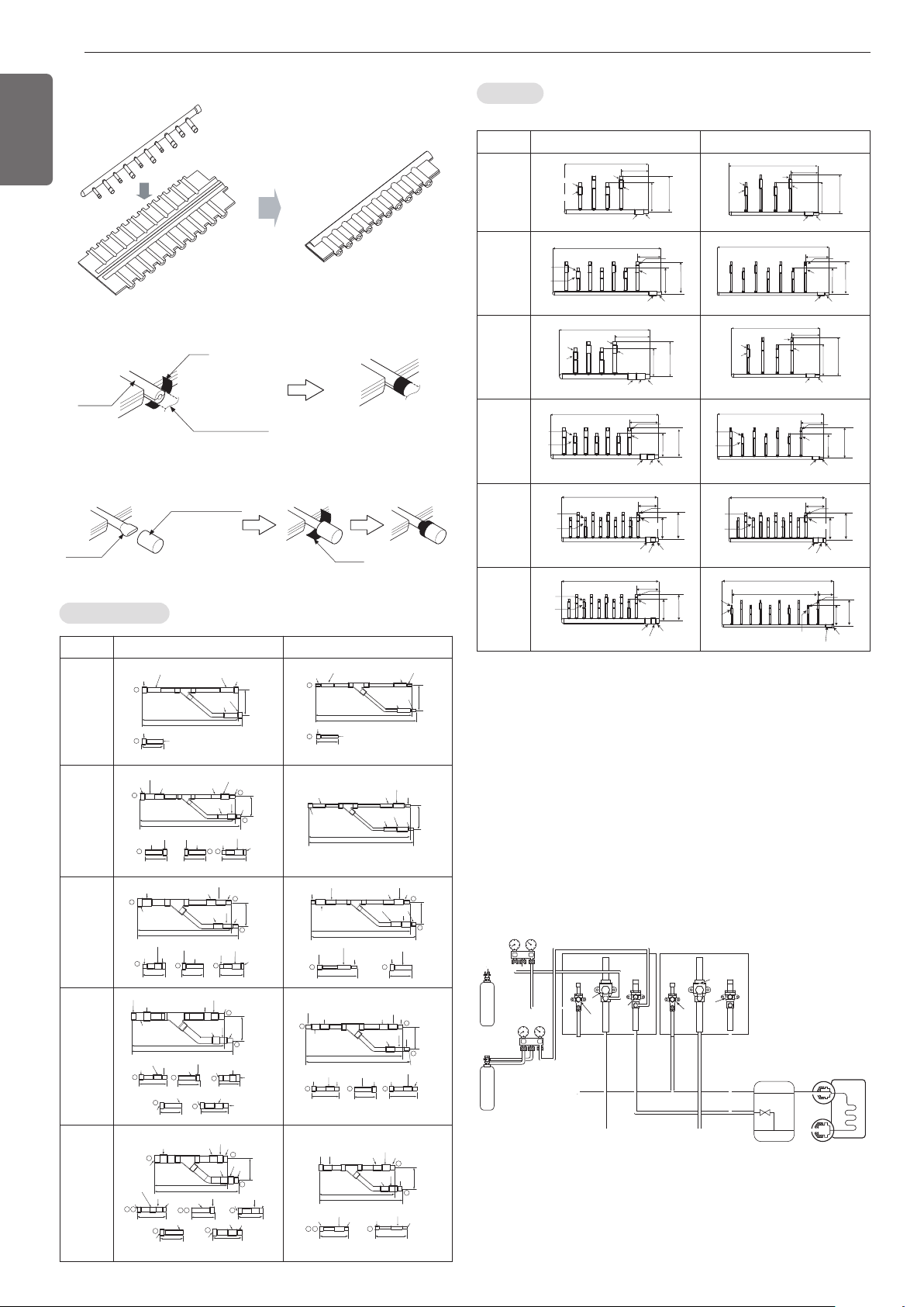
22
ENGLISH
• Header should be insulated with the insulator in each kit.
• Joints between branch and pipe should be sealed with the tape in-
cluded in each kit.
• Any cap pipe should be insulated using the insulator provided with
each kit and then taped as described above.
Insulate the header using
the insulation
material attached to the
branch pipe kit
as shown in the figure.
Insulator
Insulator of field pipe
Tape
Tape
Cap pipe
Insulator for cap pipe
Y branch pipe
Models Gas pipe Liquid pipe
ARBLN
01621
I.D19.05(3/4)
O.D15.88(5/8)
I.D12.7(1/2)
I.D15.88(5/8)
I.D15.88(5/8)
I.D15.88(5/8)
I.D12.7(1/2)
I.D12.7(1/2)
292(11-1/2)
281(11-1/16)
74
(2-29/32)
70(2-3/4)
1
1
I.D12.7(1/2)
292(11-1/2)
281(11-1/16)
74
(2-29/32)
70(2-3/4)
I.D6.35(1/4)
I.D6.35(1/4)
I.D6.35(1/4)
1
1
I.D9.52(3/8)
I.D9.52(3/8)
I.D9.52(3/8)
O.D9.52(3/8)
ARBLN
03321
413(16-1/4)
390(15-11/32)
I.D19.05(3/4)
I.D19.05(3/4)
I.D19.05(3/4)
I.D12.7(1/2)
I.D12.7
(1/2)
70(2-3/4)
I.D15.88(5/8)
I.D15.88(5/8)
I.D25.4(1)
I.D25.4(1)
O.D25.4(1)
80(3-5/32)
110(4-11/32)
83
(3-9/32)
1
2
3
3
O.D19.05(3/4)
O.D19.05(3/4)
1 2
I.D22.2(7/8)
I.D22.2(7/8)
I.D22.2(7/8)
I.D28.58(1-1/8)
I.D12.7(1/2)
I.D12.7(1/2)
I.D12.7(1/2)
74
(2-29/32)
332(13-1/16)
321(12-5/8)
I.D6.35(1/4)
I.D6.35(1/4)
I.D9.52(3/8)
I.D9.52(3/8)
I.D9.52(3/8)
ARBLN
07121
I.D12.7
(1/2)
376(14-13/16)
404(15-29/32)
120(4-23/32) 120(4-23/32)
90(3-17/32)
I.D15.88(5/8)
I.D15.88(5/8)
2
3
1
2
1 3
I.D19.05(3/4)
I.D19.05(3/4)
O.D19.05(3/4)
96
(3-25/32)
I.D22.2(7/8)
I.D22.2(7/8)
O.D22.2(7/8)
I.D34.9(1-3/8)
I.D28.58(1-1/8)
I.D28.58(1-1/8)
I.D28.58(1-1/8)
O.D31.8(1-1/4)
I.D31.8(1-1/4)
I.D31.8(1-1/4)
I.D15.88(5/8)
I.D15.88(5/8)
I.D15.88(5/8)
I.D12.7(1/2)
I.D12.7(1/2)
I.D12.7(1/2)
O.D12.7(1/2)
O.D12.7(1/2)
70(2-3/4)
110(4-11/32)
371(14-19/32)
394(15-1/2)
83
(3-9/32)
2
3
3
I.D19.05(3/4)
I.D19.05(3/4)
I.D19.05(3/4)
2
I.D6.35(1/4)
I.D9.52(3/8)
I.D9.52(3/8)
ARBLN
14521
I.D12.7(1/2)
70(2-3/4)
471(18-17/32)
517(20-11/32)
125
(4-29/32)
130(5-1/8)
I.D15.88(5/8)
I.D41.3(1-5/8)
I.D41.3
(1-5/8)
I.D41.3(1-5/8)
I.D38.1(1-1/2)
I.D38.1(1-1/2)
I.D38.1(1-1/2)
O.D38.1(1-1/2)
O.D15.88(5/8)
2
3
3
2
2
3
3
120(4-23/32)
120(4-23/32)
90(3-17/32)
I.D19.05(3/4)
I.D19.05(3/4)
I.D22.2(7/8)
I.D22.2(7/8)
O.D22.2(7/8)
I.D34.9(1-3/8)
I.D34.9(1-3/8)
I.D34.9(1-3/8)
O.D34.9(1-3/8)
I.D28.58(1-1/8)
O.D28.58(1-1/8)
I.D28.58(1-1/8)
I.D12.7(1/2)
O.D12.7(1/2)
I.D12.7
(1/2)
110(4-11/32)110(4-11/32)
41616-3/8)
444(17-15/32)
O.D15.88(5/8)
I.D15.88(5/8)
I.D19.05(3/4)
I.D15.88(5/8)
I.D15.88(5/8)
I.D19.05(3/4)
I.D19.05(3/4)
O.D19.05(3/4)
80(3-5/32)
2
3
1
2 3 3
96
(3-25/32)
I.D22.2(7/8)
I.D22.2(7/8)
I.D22.2(7/8)
I.D6.35(1/4)
I.D9.52(3/8)
I.D9.52(3/8)
ARBLN
23220
O.D.
28.58(1-1/8)
I.D.
22.2(7/8)
115(4-17/32)
X2
100(4-11/32)
O.D15.88(5/8)
I.D12.7(1/2)
70(2-3/4)
O.D.
22.2(7/8)
I.D.
15.88(5/8)
I.D.
19.05(3/4)
120(4-23/32)
O.D.38.1(1-1/2)
I.D.34.9(1-3/8)
I.D.28.58(1-1/8)
O.D.44.48(1-3/4)
X2
175(6-7/8)
I.D31.8(1-1/4)
I.D.53.98(2-1/4t I.D.
25.4(1)
I.D.44.48(1-3/4)
I.D.44.48(1-3/4)
I.D38.1(1-1/2)I.D41.3(1-5/8)
I.D.44.48(1-3/4)
I.D38.1(1-1/2)
I.D41.3(1-5/8)
I.D.53.98(2-1/4)
420(16-17/32)
490(19-9/32)
134
1
2
3
32
3 3
3
3
2
O.D.
19.05(3/4)
O.12.7(1/2)
I.D.15.88(5/8)
O.12.7(1/2) .D6.35(1/4)
I.D9.52(3/8)
X2
110(4-11/32) 110(4-11/32)
I.D25.4(1) I.D.
22.2(7/8)
I.D.
19.05(3/4)
I.D.
19.05(3/4)
I.D.
22.2(7/8)
I.D.
25.4(1)
I.D.
25.4(1)
I.D.
22.2(7/8)
346(13-5/8)
379(14-29/32)
96(3-25/32)
2
3 32
3
[Unit:mm(inch)]
[Unit:mm(inch)]
Leak test
Leak test should be made by pressurizing nitrogen gas to 3.8
MPa(551.1psi). If the pressure does not drop for 24 hours, the system
passes the test. If the pressure drops, check where the nitrogen leaks.
For the test method, refer to the following figure. (Make a test with
the service valves closed. Be also sure to pressurize liquid pipe, gas
pipe and high/low pressure common pipe)
The test result can be judged good if the pressure has not be reduced
after leaving for about one day after completion of nitrogen gas pres-
surization.
Indoor unit
Liquid side
Gas side
Nitrogen
gas
cylinder
Nitrogen
gas
cylinder
Close
High Pressure
Gas pipe
High Pressure
Gas pipe
Liquide pipe
Liquide pipe
Low Pressure
Gas pipe
Low Pressure
Gas pipe
Slave 1 outside unit Master outside unit
Close
Close
Close
Close
HR unit
Close
Leak Test and Vacuum drying
Header
Models Gas pipe Liquid pipe
4 branch
ARBL054
360(14-5/32)
120(4-23/32)
ID15.88(5/8)
ID12.7(1/2)
ID12.7(1/2)
ID15.88(5/8)
ID15.88(5/8)
ID19.05(3/4)
150
(5-29/32)
ID15.88(5/8)
ID12.7(1/2)
120
(4-23/32)
ID15.88(5/8)
ID12.7(1/2)
ID9.52(3/8)
ID6.35(1/4)
ID9.52(3/8)
ID6.35(1/4)
120(4-23/32)
360(14-5/32)
ID9.52(3/8)
ID9.52(3/8)
ID6.35(1/4)
ID6.35(1/4)
ID9.52(3/8)
ID12.7(1/2)
150
(5-29/32)
ID15.88(5/8)
ID12.7(1/2)
120
(4-23/32)
ID15.88(5/8)
ID12.7(1/2)
ID9.52(3/8)
ID6.35(1/4)
ID9.52(3/8)
ID6.35(1/4)
7 branch
ARBL057
540(21-1/4)
150
(5-29/32)
ID15.88(5/8)
ID12.7(1/2)
120
(4-23/32)
120(4-23/32)
ID15.88(5/8)
ID12.7(1/2)
ID15.88(5/8)
ID12.7(1/2)
ID15.88(5/8)
ID19.05(3/4)
ID15.88(5/8)
ID12.7(1/2)
ID9.52(3/8)
ID6.35(1/4)
ID9.52(3/8)
ID6.35(1/4)
540(21-1/4)
150
(5-29/32)
ID15.88(5/8)
ID12.7(1/2)
120
(4-23/32)
120(4-23/32)
ID6.35(1/4)
ID9.52(3/8)
ID9.52(3/8)
ID12.7(1/2)
ID15.88(5/8)
ID12.7(1/2)
ID9.52(3/8)
ID6.35(1/4)
ID9.52(3/8)
ID6.35(1/4)
4 branch
ARBL104
150
(5-29/32)
400(15-23/32)
160(6-5/16)
ID15.88(5/8)ID15.88(5/8)
ID12.7(1/2)ID12.7(1/2)
ID15.88(5/8)
ID12.7(1/2)
ID19.05(3/4)
ID15.88(5/8)
ID22.2(7/8)
ID28.58(1-1/8)
ID25.4(1)
120
(4-23/32)
ID15.88(5/8)
ID12.7(1/2)
ID9.52(3/8)
ID6.35(1/4)
ID9.52(3/8)
ID6.35(1/4)
ID15.88(5/8)
ID12.7(1/2)
ID15.88(5/8)
ID12.7(1/2)
ID9.52(3/8)
ID6.35(1/4)
ID9.52(3/8)
ID6.35(1/4)
150
(5-29/32)
120(4-23/32)
120
(4-23/32)
360(14-5/32)
ID9.52(3/8)
ID9.52(3/8)
ID6.35(1/4)
ID6.35(1/4)
ID9.52(3/8)
ID12.7(1/2)
7 branch
ARBL107
ID15.88(5/8)
ID12.7(1/2)
120
(4-23/32)
160(6-5/16)
580(22-27/32)
ID19.05(3/4)
ID15.88(5/8)
ID15.88(5/8)ID15.88(5/8)
ID12.7(1/2)ID12.7(1/2)
ID15.88(5/8)
ID12.7(1/2)
ID22.2(7/8)
ID28.58(1-1/8)
ID25.4(1)
ID9.52(3/8)
ID6.35(1/4)
ID9.52(3/8)
ID6.35(1/4)
150
(5-29/32)
ID15.88(5/8)
ID12.7(1/2)
120
(4-23/32)
ID15.88(5/8)
ID12.7(1/2)
700(27-9/16)
120(4-23/32)
ID6.35(1/4)
ID9.52(3/8)
ID9.52(3/8)ID9.52(3/8)
ID6.35(1/4)ID6.35(1/4)
ID9.52(3/8)
ID6.35(1/4)
ID9.52(3/8)ID12.7(1/2)
ID9.52(3/8)
ID6.35(1/4)
150
(5-29/32)
10 branch
ARBL1010
ID15.88(5/8)
ID12.7(1/2)
ID15.88(5/8)
ID12.7(1/2)
ID9.52(3/8)
ID6.35(1/4)
ID15.88(5/8)
ID12.7(1/2)
ID9.52(3/8)
ID6.35(1/4)
120
(4-23/32)
160(6-5/16)
760(29-28/32)
ID19.05(3/4)
ID15.88(5/8)
ID22.2(7/8)
ID28.58(1-1/8)
ID25.4(1)
150
(5-29/32)
ID15.88(5/8)
ID12.7(1/2)
ID15.88(5/8)
ID12.7(1/2)
ID9.52(3/8)
ID6.35(1/4)
ID15.88(5/8)
ID12.7(1/2)
ID9.52(3/8)
ID6.35(1/4)
120
(4-23/32)
160(6-5/16)
760(29-28/32)
ID19.05(3/4)
ID15.88(5/8)
ID22.2(7/8)
ID28.58(1-1/8)
ID25.4(1)
150
(5-29/32)
10 branch
ARBL2010
ID15.88(5/8)
ID12.7(1/2)
ID15.88(5/8)
ID12.7(1/2)
ID9.52(3/8)
ID6.35(1/4)
ID9.52(3/8)
ID6.35(1/4)
120
(4-23/32)
182(7-5/32)
775(30-17/32)
ID19.05(3/4)
ID15.88(5/8)
ID15.88(5/8)
ID12.7(1/2)
ID28.58(1-1/8)
ID31.8(1-1/4)
ID34.9(1-3/8)
150
(5-29/32)
ID15.88(5/8)
ID12.7(1/2)
120
(4-23/32)
ID15.88(5/8)
ID12.7(1/2)
ID9.52(3/8)
ID6.35(1/4)
107(4-7/32)
60*9=540(21-1/2)
700(27-9/16)
ID6.35(1/4)
ID9.52(3/8)
ID19.05(3/4)
ID15.88(5/8)
ID9.52(3/8)
ID6.35(1/4)
ID9.52(3/8)
ID6.35(1/4)
150
(5-29/32)
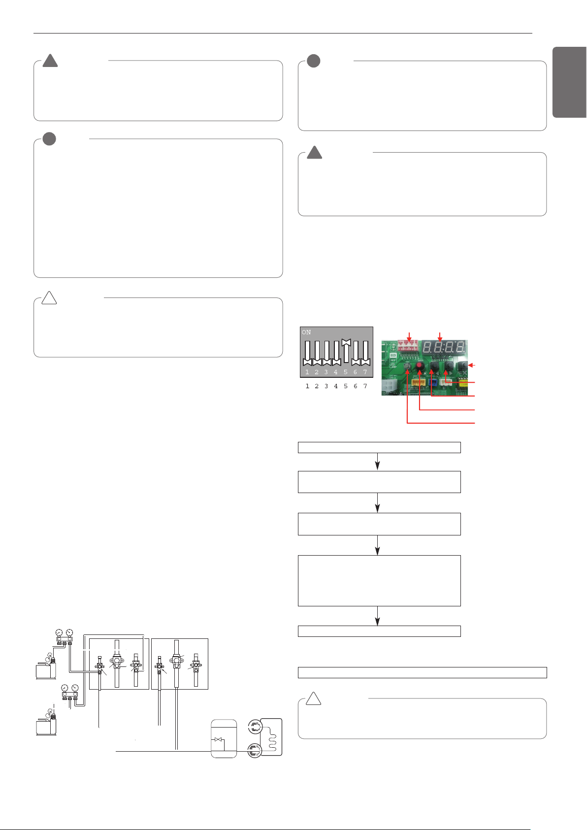
23
ENGLISH
NOTE
!
If the ambient temperature differs between the time when pressure is applied
and when the pressure drop is checked, apply the following correction factor
There is a pressure change of approximately 0.01Mpa(1.5psi) for each 33.8°F
of temperature difference.
Correction= (Temp. at the time of pressurization – Temp. at the time of check)
X 0.1
For example: Temperature at the time of pressurization
3.8MPa(551psi) is 80.6°F
24 hour later: 3.73MPa(541psi), 68°F
In this case the pressure drop of 0.07MPa(10psi) is
because of temperature drop
And hence there is no leakage in pipe occurred.
CAUTION
To prevent the nitrogen from entering the refrigeration system in
the liquid state, the top of the cylinder must be at higher position
than the bottom when you pressurize the system.
Usually the cylinder is used in a vertical standing position.
!
WARNING
Use a vacuum pump or Inert(nitrogen) gas when doing leakage
test or air purge. Do not compress air or Oxygen and do not use
Flammable gases. Otherwise, it may cause fire or explosion.
- There is the risk of death, injury, fire or explosion.
!
Vacuum
Vacuum drying should be made from the service port provided on the outdoor
unit’s service valve to the vacuum pump commonly used for liquid pipe, gas pipe
and high/low pressure common pipe. (Make Vacuum from liquid pipe, gas pipe and
high/low pressure common pipe with the service valve closed.)
* Never perform air purging using refrigerant.
• Vacuum drying: Use a vacuum pump that can evacuate to -100.7kPa (-
14.6psi, 5 Torr, -755mmHg).
- Evacuate the system from the liquid and gas pipes with a vacuum pump
for over 2 hrs and bring the system to -100.7kPa(-14.6psi). After maintain-
ing system under that condition for over 1 hr, confirm the vacuum gauge
rises. The system may contain moisture or leak.
- Following should be executed if there is a possibility of moisture remain-
ing inside the pipe.
(Rainwater may enter the pipe during work in the rainy season or over a
long period of time)
After evacuating the system for 2 hrs, give pressure to the system to
0.05MPa(7.3psi) (vacuum break) with nitrogen gas and then evacuate it
again with the vacuum pump for 1hr to -100.7kPa(-14.6psi)(vacuum dry-
ing). If the system cannot be evacuated to -100.7kPa(-14.6psi) within 2
hrs, repeat the steps of vacuum break and its drying. Finally, check if the
vacuum gauge does not rise or not, after maintaining the system in vac-
uum for 1 hr.
Indoor unit
Liquid side
Gas side
High Pressure
Gas pipe
High Pressure
Gas pipe
Liquide pipe
Liquide pipe
Low Pressure
Gas pipe
Low Pressure
Gas pipe
HR unit
Scale
Use a graviometer. (One that can
measure down to 0.1kg). If you are
unable to prepare such a
high-precision gravimeter you may use
a charge cylinder.
Slave 1 outside unit Master outside unit
Close
Close
Close
Vacuum
pump
Vacuum
pump
Close
Close
Close
NOTE
!
Always add an appropriate amount of refrigerant. (For the refrigerant addi-
tional charge)
Too much or too little refrigerant will cause trouble.
To use the Vacuum Mode
(If the Vacuum mode is set, all valves of Indoor units and Outdoor units will
be opened.)
WARNING
When installing and moving the air conditioner to another site,
recharge after perfect evacuation.
- If a different refrigerant or air is mixed with the original refriger-
ant, the refrigerant cycle may malfunction and the unit may be
damaged.
!
This function is used for creating vacuum in the system after compres-
sor replacement, ODU parts replacement or IDU addition/replacement.
Vacuum mode setting method
Vacuum mode off method
CAUTION
ODU operation stops during vacuum mode. Compressor can't
operate.
Master unit PCB DIP switch on : No.5
Vacuum mode
Select the mode using ‘▶’, ‘◀’ Button :
“SVC” Push the ‘●’ button
Select the Function using ‘▶’, ‘◀’ Button :
“Se1” Push the ‘●’ button
Start the vacuum mode : “VACC”
ODU V/V open
ODU EEV open
IDU EEV open
Dip switch off and push the reset button on Master unit PCB
!
Vacuum Mode
DIP SWITCH 7-Segment
SW01C ( : confirm)
SW02C ( : backward
: forward)
SW04C
( X : cancel)
SW01D (reset)
SW03C (
ȭ
ȯ
Ɨ
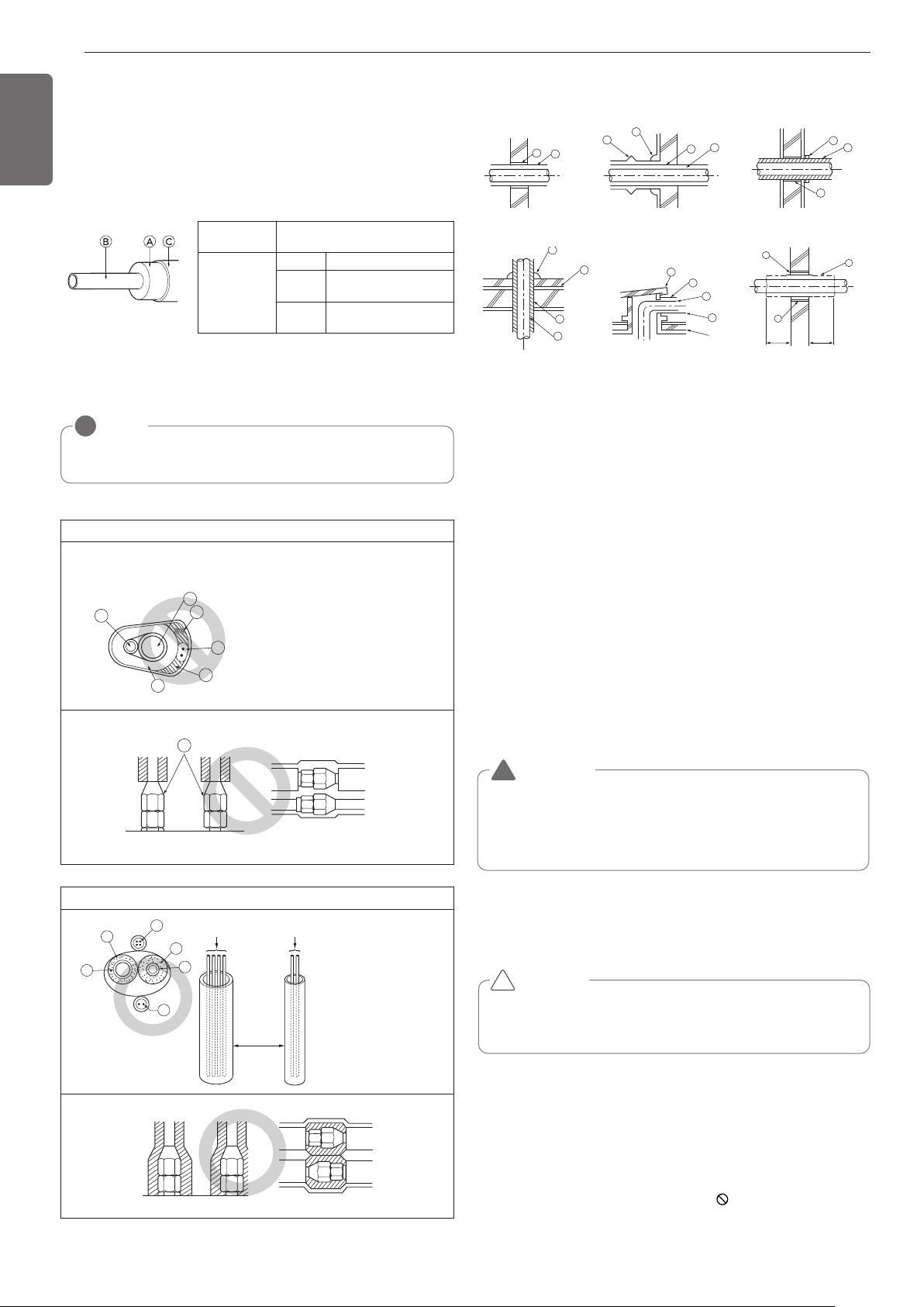
24
ENGLISH
Be sure to give insulation work to refrigerant piping by covering liquid
pipe and gas pipe separately with enough thickness heat-resistant poly-
ethylene, so that no gap is observed in the joint between indoor unit
and insulating material, and insulating materials themselves. When in-
sulation work is insufficient, there is a possibility of condensation drip,
etc. Pay special attention to insulation work to ceiling plenum.
Ⓐ Heat insulation material
Ⓑ Pipe
Ⓒ Outer covering(Wind the connection part and cutting part of heat in-
sulation material with a finishing tape.)
Heat insulation
material
Adhesive + Heat - resistant poly-
ethylene foam + Adhesive tape
Outer
covering
Indoor Vinyl tape
Floor ex-
posed
Water-proof hemp cloth +
Bronze asphalt
Outdoor
Water-proof hemp cloth +
Zinc plate + Oily paint
NOTE
!
When using polyethylene cover as covering material, asphalt roof-
ing shall not be required.
Bad example
Thermal insulation of refrigerant piping
• Do not insulate gas or low pressure pipe and liquid or highpres-
sure pipe together.
• Be sure to fully insulate connecting portion.
Ⓐ
These parts are not insulated.
Ⓐ Liquid pipe
Ⓑ Gas pipe
ⓒ Power lines
ⓓ
Finishing tape
ⓔ
Insulating material
ⓕ
Communication lines
A
C
D
E
B
F
A
Good example
Ⓐ Liquid pipe
Ⓑ Gas pipe
ⓒ Power lines
ⓓ
Insulating material
ⓔ
Communication lines
Communication lines
Separation
Power lines
E
D
D
B
A
C
A
B
E
B
I
A
B
D
C
1m1m
D
F
G
B
G
D
B
H
I
J
A
Penetrations
Ⓐ Sleeve
Ⓑ Heat insulating material
Ⓒ Lagging
Ⓓ Caulking material
Ⓔ Band
Ⓕ Waterproofing layer
Ⓖ Sleeve with edge
Ⓗ Lagging material
Ⓘ Mortar or other incombustible caulking
Ⓙ Incombustible heat insulation material
When filling a gap with mortar, cover the penetration part with steel plate so
that the insulation material will not be caved in. For this part, use incom-
bustible materials for both insulation and covering. (Vinyl covering should not
be used.)
Inner wall (concealed) Outer wall Outer wall (exposed)
Floor (fireproofing)
Penetrating portion on fire
limit and boundary wall
Roof pipe shaft
CAUTION
- Follow ordinance of your governmental organization for technical
standard related to electrical equipment, wiring regulations and guid-
ance of each electric power company.
-
Install the Outside Unit communication cable away from the power
source wiring so that it is not affected by electric noise from the power
source. (Do not run it through the same conduit.)
- Be sure to provide designated grounding work to Outside Unit.
- Give some allowance to wiring for electrical part box of Indoor and
Outside Units, because the box is sometimes removed at the time of
service work.
- Never connect the main power source to terminal block of communi-
cation cable. If connected, electrical parts will be burnt out.
- Use 2-core shield cable for communication cable.(O mark in the figure
below) If communication cable of different systems are wired with
the same multiplecore cable, the resultant poor transmitting and re-
ceiving will cause erroneous operations. ( mark in the figure
below)
- Only the communication cable specified should be connected to the
terminal block for Outside Unit communication.
CAUTION
Be sure to correct the outside unit to earth. Do not connect ground
wire to any gas pipe, liquid pipe, lightening rod or telephone earth
line. If earth is incomplete, it may cause an electric shock.
!
WARNING
Be sure to have authorized electrical engineers do the electric
work using special circuits in accordance with regulations and this
installation manual.
If power supply circuit has a lack of capacity or electric work defi-
ciency, it may cause an electric shock or fire.
!
ELECTRICAL WIRING
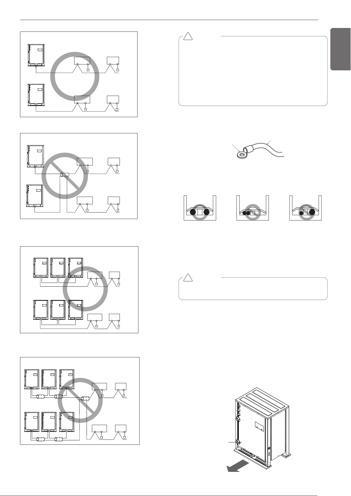
25
ENGLISH
2-Core Shield Cable
Multi-Core Cable
Remote
control
Remote
control
Remote
control
Remote
control
Indoor
Unit
Outside Unit
Indoor
Unit
Indoor
Unit
Indoor
Unit
Outside Unit
Outside Unit
Remote
control
Remote
control
Indoor
Unit
Indoor
Unit
Remote
control
Remote
control
Indoor
Unit
Indoor
Unit
Master Slave1 Slave2
Master Slave1 Slave2
Remote
controller
Remote
controller
Indoor
Unit
Indoor
Unit
Remote
controller
Outside unit
Outside unit
Remote
controller
Indoor
Unit
Indoor
Unit
Master Slave1 Slave2
Master Slave1 Slave2
Outside unit
Outside unit
Remote
controller
Remote
controller
Indoor
Unit
Indoor
Unit
Remote
controller
Remote
controller
Indoor
Unit
Indoor
Unit
2-Core Shield Cable
Multi-Core Cable
CAUTION
When the 400 volt power supply is applied to “N” phase by mistake,
check damaged parts in control box and replace them.
Precautions when laying power wiring
Use round pressure terminals for connections to the power terminal
block.
Round pressure terminal
Power cable
When none are available, follow the instructions below.
- Do not connect wiring of different thicknesses to the power terminal
block. (Slack in the power wiring may cause abnormal heat.)
- When connecting cable which is the same thickness, do as shown in
the figure below.
- For wiring, use the designated power cable and connect firmly, then
secure to prevent outside pressure being exerted on the terminal
block.
- Use an appropriate screwdriver for tightening the terinal screws. A
screwdriver with a small head will strip the head and make proper
tighterning impossible.
- Over-tightening the terminal screws may break them.
!
Control Box and Wiring Location
- Remove all of the screws at front panel and remove the panel by
pulling it forward.
- Connect communication cable between main and sub outside unit
through the terminal block.
- Connect communication cables between outside unit and indoor
units through the terminal block.
- When the central control system is connected to the outside unit, a
dedicated PCB must be connected between them.
- When connecting communication cable between outside unit and in-
door units with shielded cable, connect the shield ground to the earth
screw.
Front
Panel
CAUTION
• Use the 2-core shield cables for communication cables. Never use
them together with power cables.
• The conductive shielding layer of cable should be grounded to the
metal part of both units.
• Never use multi-core cable
• As this unit is equipped with an inverter, to install a phase leading
capacitor not only will deteriorate power factor improvement effect,
but also may cause capacitor abnormal heating. Therefore, never in-
stall a phase leading capacitor.
• Make sure that the power unbalance ratio is not greater than 2%. If
it is greater the units lifespan will be reduced.
!
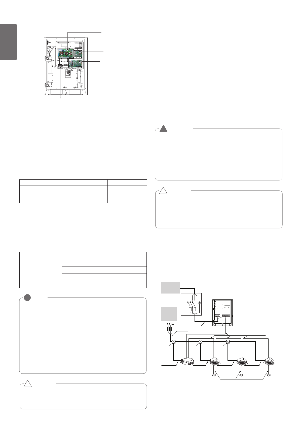
26
ENGLISH
Communication and Power Cables
Communication cable
- Types : shielding wire
- Cross section : 1.0~1.5mm
2
(AWG16)
- Insulation material : PVC
- Maximum allowable temperature: 60°C(140°F)
- Maximum allowable cable length: under 300m(984ft)
Remote control cable
- Types : 3-core cable
Central control cable
Separation of communication and power cables
- If communication and power cables are run alongside each other then
there is a strong likelihood of operational faults developing due to in-
terference in the signal wiring caused by electrostatic and electro-
magnetic coupling.
The tables below indicates our recommendation as to appropriate
spacing of communication and power cables where these are to be
run side by side
Current capacity of power cable Spacing
100V or more
10A 300mm(11-13/16inch)
50A 500mm(19-11/16inch
100A 1,000mm(39-3/8inch
Exceed 100A 1,500mm(59-1/16inch
Main PCB
Noise Filter
External PCB
Take care of the
phase sequence of
3-phase 3-wire
power system
NOTE
!
• The figures are based on assumed length of parallel cabling up
to 100m(328ft). For length in excess of 100m(328ft) the figures
will have to be recalculated in direct proportion to the additional
length of cable involved.
• If the power supply waveform continues to exhibit some distor-
tion the recommended spacing in the table should be increased.
- If the cable are laid inside conduits then the following point
must also be taken into account when grouping various cable
together for introduction into the conduits
- Power cable(including power supply to air conditioner) and
communication cables
must not be laid inside the same
- In the same way, when grouping the power wires and com-
munication cables should not be bunched together.
CAUTION
• If apparatus is not properly earthed then there is always a risk of
electric shocks, the earthing of the
apparatus must be carried out by a qualified person.
!
Wiring of main power supply and equipment
capacity
- Use a separate power supply for the Outside Unit and Indoor Unit.
- Bear in mind ambient conditions (ambient temperature,direct sun-
light, rain water,etc.) when proceeding with the wiring and connec-
tions.
- The cable size is the minimum value for metal conduit wiring. The
power cord size should be 1 rank thicker taking into account the line
voltage drops. Make sure the power-supply voltage does not drop
more than 10%.
- Specific wiring requirements should adhere to the wiring regulations
of the region.
- Power supply cords of parts of appliances for outdoor use should not
be lighter than polychloroprene sheathed flexible cord.
- Don't install an individual switch or electrical outlet to disconnect
each of indoor unit separately from the power supply.
CAUTION
• Some installation site may require attachment of an earth leakage
breaker. If no earth leakage breaker is installed, it may cause an
electric shock.
• Do not use anything other than breaker and fuse with correct ca-
pacity. Using fuse and wire or copper wire with too large capacity
may cause a malfunction of unit or fire.
!
WARNING
• Follow ordinance of your governmental organization for techni-
cal standard related to electrical equipment, wiring regulations
and guidance of each electric power company.
• Make sure to use specified cables for connections so that no
external force is imparted to terminal connections. If connec-
tions are not fixed firmly, it may cause heating or fire.
• Make sure to use the appropriate type of overcurrent protection
switch. Note that generated overcurrent may include some
amount of direct current.
!
Field Wiring
208/230V
Example Connection of Communication Cable
1 Outdoor Unit-3Ø, 208/230V
Product type
Cable type
Diameter
ACP&AC Manager
2-core cable (Shielding cable)
1.0~1.5mm
2
( AWG16)
AC Smart
2-core cable (Shielding cable)
1.0~1.5mm
2
( AWG16)
Simple central controller
4-core cable (Shielding cable)
1.0~1.5mm
2
( AWG16)
Switch
ELCB
Communication Line
(2 Wires Cable)
Power Line
(3 Wires Cable)
Communication Line
(3 Wires Cable)
Power Line
(2 Wires Cable)
Power Line
ELCB
(2 Wires Cable)
Power Line
(2 Wires Cable)
Power Line
(2 Wires Cable)
Power Line
(2 Wires Cable)
[Outdoor Unit]
[Indoor Units]
Power supply
3 Phase 3 Wires
60Hz 208/230V
Power supply
1 Phase 60Hz
208/230V
(Main Switch)
Pull box
(Installer option)
Pull box
(Installer option)
Pull box
(Installer option)
HR unit
L(L1) N(L2)
RST
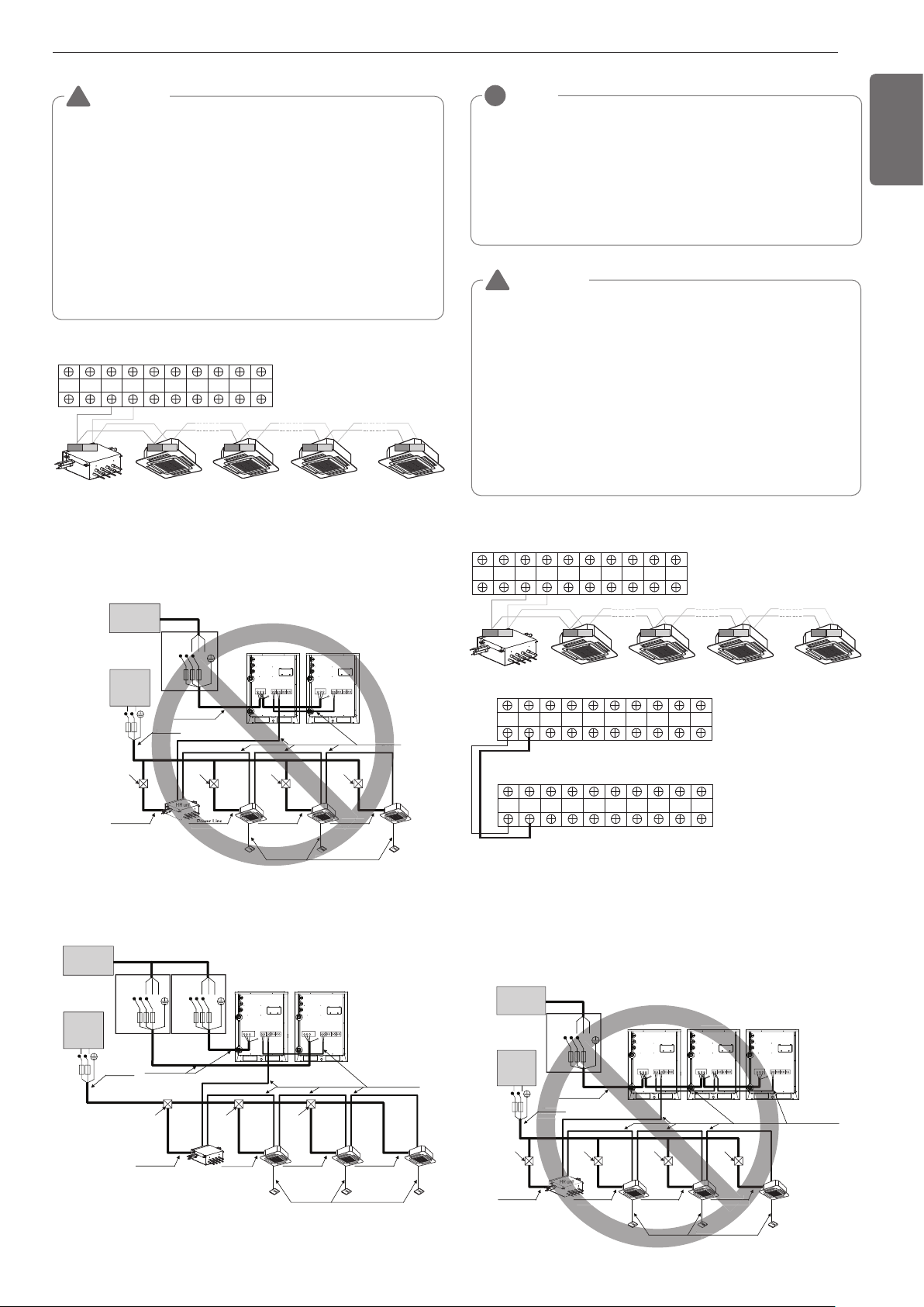
27
ENGLISH
WARNING
• Indoor Unit ground Lines are required for preventing electrical
shock accident during current leakage, Communication disorder by
noise effect and motor current leakage (without connection to
pipe).
• Don't install an individual switch or electrical outlet to disconnect
each of indoor unit separately from the power supply.
• Install the main switch that can interrupt all the power sources in an
integrated manner because this system consists of the equipment
utilizing the multiple power sources.
• If there exists the possibility of reversed phase, lose phase, mo-
mentary blackout or the power goes on and off while the product is
operating, attach a reversed phase protection circuit locally.
Running the product in reversed phase may break the compressor
and other parts.
!
Between Indoor and Master Outdoor unit
HR unit
3(A) 4(B) 3(A) 4(B) 3(A) 4(B) 3(A) 4(B)
AB
Master
Outdoor Unit
SODU. B SODU. A IDU. B IDU. A CEN. B CEN. A DRY1 DRY2 GND 12V
2 Outdoor Units-3Ø, 208/230V
When the power source is connected In series between the units.
When the power source is supplied to Each outdoor unit individually.
Communication Line
(2 Wires Cable)
Power Line
(3 Wires Cable)
Communication Line
(3 Wires Cable)
Power Line
(2 Wires Cable)
Power Line
(2 Wires Cable)
(2 Wires Cable)
Power Line
(2 Wires Cable)
Power Line
(2 Wires Cable)
[Master]
[Indoor Units]
(Main Switch)
[Slave]
Pull Box
(Installer option)
Pull Box
(Installer option)
Pull Box
(Installer option)
Pull Box
(Installer option)
nication L
es Cable
Com
Power
(2 Wires
(2 Wires C
r Line
(2 Wires Cab
[
Slave]
Power L
Wire
Power supply
3 Phase 3 Wires
60Hz 208/230V
Power supply
1 Phase 60Hz
208/230V
RST
Switch
ELCB
ELCB
L(L1) N(L2)
Switch
Communication Line
(2 Wires Cable)
Power Line
(3 Wires Cable)
Communication Line
(3 Wires Cable)
Power Line
(2 Wires Cable)
Power Line
(2 Wires Cable)
Power Line
(2 Wires Cable)
Power Line
(2 Wires Cable)
[Master]
[Indoor Units]
Power supply
3 Phase 3 Wires
60Hz 208/230V
Power supply
1 Phase 60Hz
208/230V
(Main Switch)
[Slave]
Switch
ELCBELCB
Pull box
(Installer option)
Pull box
(Installer option)
Pull box
(Installer option)
Power Line
(2 Wires Cable)
HR unit
ELCB
L(L1) N(L2)
RST RST
NOTE
!
- Field Wiring diagram is to be used as a guidelineonly. Wiring
should comply with applicable local and national codes
- ELCB must have function to prevent electrical short and over cur-
rent at the same time .
- Use copper wires only.
- Unit must be grounded in compliance with the applicable local
and national codes.
- ELCB and fuse/breaker must install to the power line
WARNING
• Indoor Unit ground Lines are required for preventing electrical shock
accident during current leakage, Communication disorder by noise
effect and motor current leakage (without connection to pipe).
• Don't install an individual switch or electrical outlet to disconnect
each of indoor unit separately from the power supply.
• Install the main switch that can interrupt all the power sources in an
integrated manner because this system consists of the equipment
utilizing the multiple power sources.
• If there exists the possibility of reversed phase, lose phase, momen-
tary blackout or the power goes on and off while the product is op-
erating, attach a reversed phase protection circuit locally.
Running the product in reversed phase may break the compressor
and other parts.
!
Master
Outdoor Unit
SODU. B SODU. A IDU. B IDU. A CEN. B CEN. A DRY1 DRY2 GND 12V
SODU. B SODU. A IDU. B IDU. A CEN. B CEN. A DRY1 DRY2 GND 12V
Slave
Outdoor Unit
HR unit
AB
3(A) 4(B) 3(A) 4(B) 3(A) 4(B) 3(A) 4(B)
Master
Outdoor Unit
SODU. B SODU. A IDU. B IDU. A CEN. B CEN. A DRY1 DRY2 GND 12V
Between Indoor and Master Outdoor unit
• It is not the point to make ground connection.
- Make sure that terminal number of master and slave outdoor units
are matched.(A-A,B-B)
3 Outdoor Units-3Ø, 208/230V
When the power source is connected In series between the units.
Communication Line
(2 Wires Cable)
Power Line
(3 Wires Cable)
Communication Line
(3 Wires Cable)
Power Line
(2 Wires Cable)
Power Line
(2 Wires Cable)
Power Line
(2 Wires Cable)
Power Line
(2 Wires Cable)
Power Line
(2 Wires Cable)
[Master]
[Indoor Units]
(Main Switch)
[Slave1] [Slave2]
Pull Box
(Installer option)
Pull Box
(Installer option)
Pull Box
(Installer option)
Pull Box
(Installer option)
Communic
(3 W
Po
(2 Wire
ne
Cable)
Power
(2 Wires
[Master]
[Slave1]
Power Line
2 Wires Ca
)
Switch
ELCB
ELCB
Power supply
3 Phase 3 Wires
60Hz 208/230V
Power supply
1 Phase 60Hz
208/230V
L(L1) N(L2)
RST
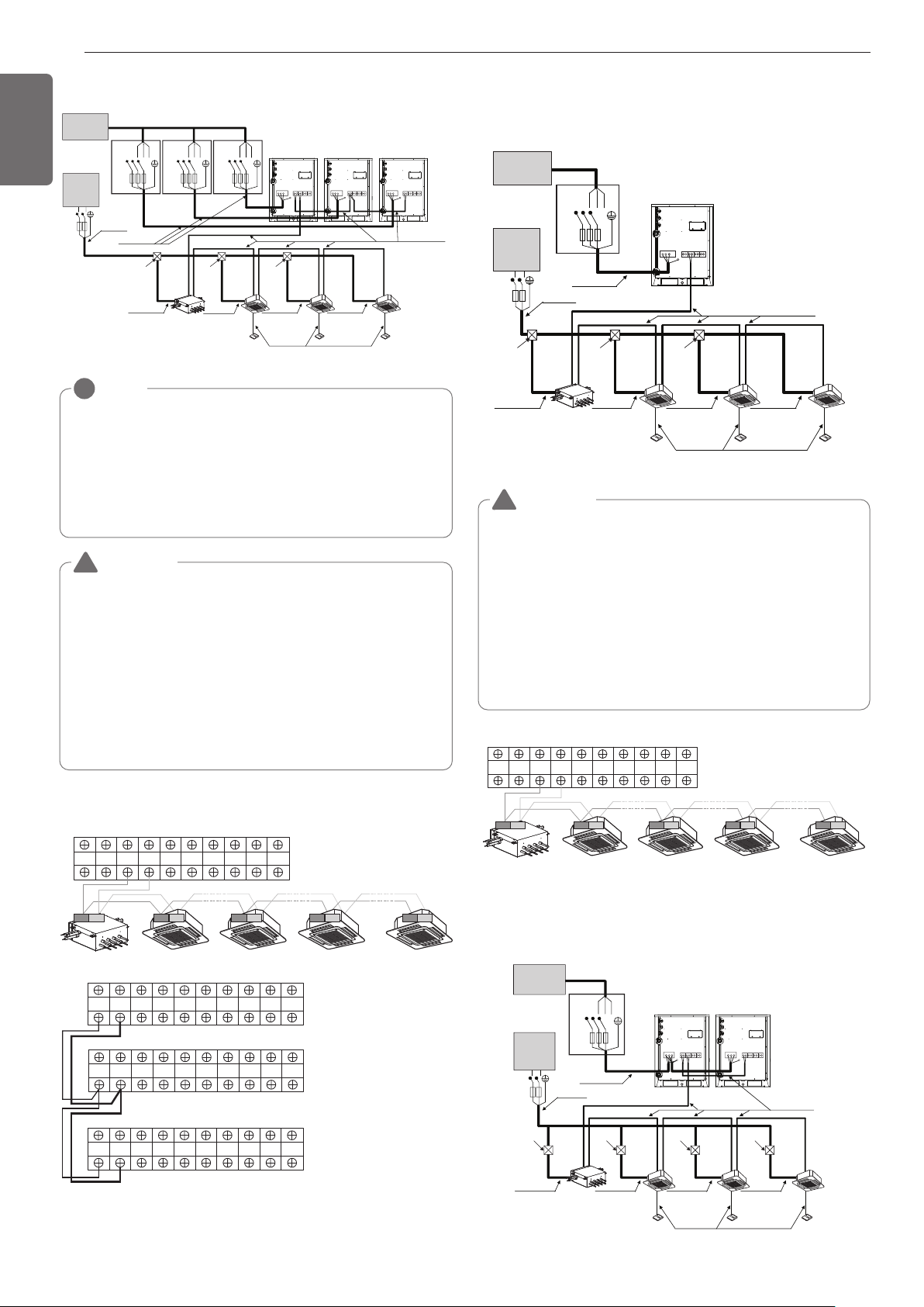
28
ENGLISH
Switch
Communication Line
(2 Wires Cable)
Power Line
(3 Wires Cable)
Communication Line
(3 Wires Cable)
Power Line
(2 Wires Cable)
Power Line
(2 Wires Cable)
Power Line
(2 Wires Cable)
Power Line
(2 Wires Cable)
[Master]
[Indoor Units]
Power supply
3 Phase 3 Wires
60Hz 208/230V
Power supply
1 Phase 60Hz
208/230V
(Main Switch)
[Slave1] [Slave2]
Switch Switch
ELCB ELCB ELCB
Pull box
(Installer option)
Pull box
(Installer option)
Pull box
(Installer option)
Power Line
(2 Wires Cable)
HR unit
ELCB
L(L1) N(L2)
RST RST RST
When the power source is supplied to Each outdoor unit individually.
NOTE
!
- Field Wiring diagram is to be used as a guidelineonly. Wiring
should comply with applicable local and national codes
- ELCB must have function to prevent electrical short and over cur-
rent at the same time .
- Use copper wires only.
- Unit must be grounded in compliance with the applicable local and
national codes.
- ELCB and fuse/breaker must install to the power line
Master
Outdoor Unit
SODU. B SODU. A IDU. B IDU. A CEN. B CEN. A DRY1 DRY2 GND 12V
Master
Outdoor Unit
SODU. B SODU. A IDU. B IDU. A CEN. B CEN. A DRY1 DRY2 GND 12V
SODU. B SODU. A IDU. B IDU. A CEN. B CEN. A DRY1 DRY2 GND 12V
SODU. B SODU. A IDU. B IDU. A CEN. B CEN. A DRY1 DRY2 GND 12V
Slave1
Outdoor Unit
HR unit
Slave2
Outdoor Unit
AB
3(A) 4(B) 3(A) 4(B) 3(A) 4(B) 3(A) 4(B)
Between Indoor and Master Outdoor unit
• It is not the point to make ground connection.
- Make sure that terminal number of master and slave outdoor units
are matched.(A-A,B-B)
WARNING
• Indoor Unit ground Lines are required for preventing electrical shock
accident during current leakage, Communication disorder by noise
effect and motor current leakage (without connection to pipe).
• Don't install an individual switch or electrical outlet to disconnect
each of indoor unit separately from the power supply.
• Install the main switch that can interrupt all the power sources in an
integrated manner because this system consists of the equipment
utilizing the multiple power sources.
• If there exists the possibility of reversed phase, lose phase, momen-
tary blackout or the power goes on and off while the product is oper-
ating, attach a reversed phase protection circuit locally.
Running the product in reversed phase may break the compressor
and other parts.
!
460V
Example Connection of Communication Cable
1 Outdoor Unit-3Ø, 460V
WARNING
• Indoor Unit ground Lines are required for preventing electrical shock
accident during current leakage, Communication disorder by noise
effect and motor current leakage (without connection to pipe).
• Don't install an individual switch or electrical outlet to disconnect
each of indoor unit separately from the power supply.
• Install the main switch that can interrupt all the power sources in an
integrated manner because this system consists of the equipment
utilizing the multiple power sources.
• If there exists the possibility of reversed phase, lose phase, momen-
tary blackout or the power goes on and off while the product is oper-
ating, attach a reversed phase protection circuit locally.
Running the product in reversed phase may break the compressor
and other parts.
!
Switch
ELCB
Communication Line
(2 Wires Cable)
Power Line
(3 Wires Cable)
Communication Line
(3 Wires Cable)
Power Line
(2 Wires Cable)
Power Line
ELCB
(2 Wires Cable)
Power Line
(2 Wires Cable)
Power Line
(2 Wires Cable)
Power Line
(2 Wires Cable)
[Outdoor Unit]
[Indoor Units]
Power supply
3 Phase 3 Wires
60Hz 460V
Power supply
1 Phase 60Hz
208/230V
(Main Switch)
Pull box
(Installer option)
Pull box
(Installer option)
Pull box
(Installer option)
HR unit
L(L1) N(L2)
RST
Master
Outdoor Unit
SODU. B SODU. A IDU. B IDU. A CEN. B CEN. A DRY1 DRY2 GND 12V
Between Indoor and Master Outdoor unit
HR unit
AB
3(A) 4(B) 3(A) 4(B) 3(A) 4(B) 3(A) 4(B)
2 Outdoor Units-3Ø, 460V
When the power source is connected In series between the units.
Communication Line
(2 Wires Cable)
Power Line
(3 Wires Cable)
Communication Line
(3 Wires Cable)
Power Line
(2 Wires Cable)
Power Line
(2 Wires Cable)
Power Line
(2 Wires Cable)
Power Line
(2 Wires Cable)
Power Line
(2 Wires Cable)
[Master]
[Indoor Units]
(Main Switch)
[Slave]
Pull Box
(Installer option)
Pull Box
(Installer option)
Pull Box
(Installer option)
Pull Box
(Installer option)
HR unit
Power supply
3 Phase 3 Wires
60Hz 460V
Power supply
1 Phase 60Hz
208/230V
Switch
ELCB
ELCB
L(L1) N(L2)
RST
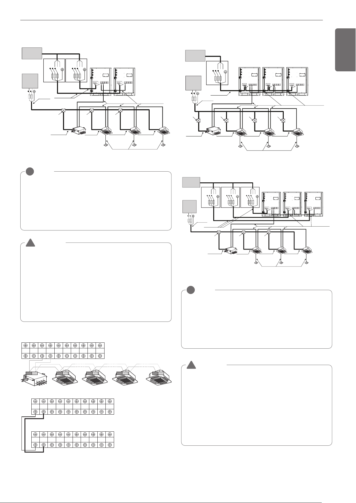
29
ENGLISH
Switch
Communication Line
(2 Wires Cable)
Power Line
(3 Wires Cable)
Communication Line
(3 Wires Cable)
Power Line
(2 Wires Cable)
Power Line
(2 Wires Cable)
Power Line
(2 Wires Cable)
Power Line
(2 Wires Cable)
[Master]
[Indoor Units]
Power supply
3 Phase 3 Wires
60Hz 460V
Power supply
1 Phase 60Hz
208/230V
(Main Switch)
[Slave]
Switch
ELCBELCB
Pull box
(Installer option)
Pull box
(Installer option)
Pull box
(Installer option)
Power Line
(2 Wires Cable)
HR unit
ELCB
L(L1) N(L2)
RST RST
When the power source is supplied to Each outdoor unit individually.
NOTE
!
- Field Wiring diagram is to be used as a guideline only. Wiring
should comply with applicable local and national codes
- ELCB must have function to prevent electrical short and over cur-
rent at the same time .
- Use copper wires only.
- Unit must be grounded in compliance with the applicable local and
national codes.
- ELCB and fuse/breaker must install to the power line
Master
Outdoor Unit
SODU. B SODU. A IDU. B IDU. A CEN. B CEN. A DRY1 DRY2 GND 12V
Slave
Outdoor Unit
SODU. B SODU. A IDU. B IDU. A CEN. B CEN. A DRY1 DRY2 GND 12V
Master
Outdoor Unit
SODU. B SODU. A IDU. B IDU. A CEN. B CEN. A DRY1 DRY2 GND 12V
HR unit
AB
3(A) 4(B) 3(A) 4(B) 3(A) 4(B) 3(A) 4(B)
Between Indoor and Master Outdoor unit
• It is not the point to make ground connection.
- Make sure that terminal number of master and slave outdoor units
are matched.(A-A,B-B)
WARNING
• Indoor Unit ground Lines are required for preventing electrical shock
accident during current leakage, Communication disorder by noise
effect and motor current leakage (without connection to pipe).
• Don't install an individual switch or electrical outlet to disconnect
each of indoor unit separately from the power supply.
• Install the main switch that can interrupt all the power sources in an
integrated manner because this system consists of the equipment
utilizing the multiple power sources.
• If there exists the possibility of reversed phase, lose phase, momen-
tary blackout or the power goes on and off while the product is oper-
ating, attach a reversed phase protection circuit locally.
Running the product in reversed phase may break the compressor
and other parts.
!
3 Outdoor Units-3Ø, 460V
When the power source is connected In series between the units.
Communication Line
(2 Wires Cable)
Power Line
(3 Wires Cable)
Communication Line
(3 Wires Cable)
Power Line
(2 Wires Cable)
Power Line
(2 Wires Cable)
Power Line
(2 Wires Cable)
Power Line
(2 Wires Cable)
Power Line
(2 Wires Cable)
[Master]
[Indoor Units]
(Main Switch)
[Slave1] [Slave2]
Pull Box
(Installer option)
Pull Box
(Installer option)
Pull Box
(Installer option)
Pull Box
(Installer option)
HR unit
Switch
ELCB
ELCB
Power supply
3 Phase 3 Wires
60Hz 460V
Power supply
1 Phase 60Hz
208/230V
L(L1) N(L2)
RST
Switch
Communication Line
(2 Wires Cable)
Power Line
(3 Wires Cable)
Communication Line
(3 Wires Cable)
Power Line
(2 Wires Cable)
Power Line
(2 Wires Cable)
Power Line
(2 Wires Cable)
Power Line
(2 Wires Cable)
[Master]
[Indoor Units]
Power supply
3 Phase 3 Wires
60Hz 460V
Power supply
1 Phase 60Hz
208/230V
(Main Switch)
[Slave1] [Slave2]
Switch Switch
ELCB ELCB ELCB
Pull box
(Installer option)
Pull box
(Installer option)
Pull box
(Installer option)
Power Line
(2 Wires Cable)
HR unit
ELCB
L(L1) N(L2)
RST RST RST
When the power source is supplied to Each outdoor unit individually.
NOTE
!
- Field Wiring diagram is to be used as a guideline only. Wiring
should comply with applicable local and national codes
- ELCB must have function to prevent electrical short and over cur-
rent at the same time .
- Use copper wires only.
- Unit must be grounded in compliance with the applicable local
and national codes.
- ELCB and fuse/breaker must install to the power line
WARNING
• Indoor Unit ground Lines are required for preventing electrical shock
accident during current leakage, Communication disorder by noise
effect and motor current leakage (without connection to pipe).
• Don't install an individual switch or electrical outlet to disconnect
each of indoor unit separately from the power supply.
• Install the main switch that can interrupt all the power sources in an
integrated manner because this system consists of the equipment
utilizing the multiple power sources.
• If there exists the possibility of reversed phase, lose phase, momen-
tary blackout or the power goes on and off while the product is oper-
ating, attach a reversed phase protection circuit locally.
Running the product in reversed phase may break the compressor
and other parts.
!
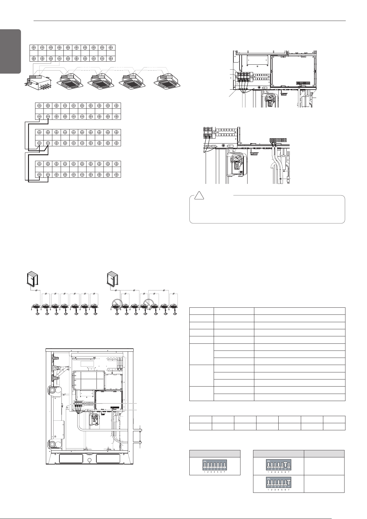
30
ENGLISH
Master
Outdoor Unit
SODU. B SODU. A IDU. B IDU. A CEN. B CEN. A DRY1 DRY2 GND 12V
SODU. B SODU. A IDU. B IDU. A CEN. B CEN. A DRY1 DRY2 GND 12V
SODU. B SODU. A IDU. B IDU. A CEN. B CEN. A DRY1 DRY2 GND 12V
Master
Outdoor Unit
SODU. B SODU. A IDU. B IDU. A CEN. B CEN. A DRY1 DRY2 GND 12V
Slave1
Outdoor Unit
HR unit
AB
Slave2
Outdoor Unit
3(A) 4(B) 3(A) 4(B) 3(A) 4(B) 3(A) 4(B)
Between Indoor and Master Outdoor unit
• It is not the point to make ground connection.
- Make sure that terminal number of master and slave outdoor units
are matched.(A-A,B-B)
Example) Connection of Communication Cable
[BUS type] [STAR type]
- Connection of communication
cable must be installed like
below figure between indoor
unit to outside unit .
- Abnormal operation can be
caused by communication de-
fect, when connection of com-
munication cable is installed like
below figure(STAR type).
Example) Connection of power and communication cable (UWC)
Main power
terminal block
Ground wire
Power/
Ground cable
Over
50mm
(1.97inch)
gap
Communication
cable
Main power
terminal block
Insulation sleeves
attachments
Fix firmly not
to be displaced
ODU-IDU
Communication cable
ODU-ODU
Communication cable
Main Power Connection
Communication Connection
CAUTION
It should be wiring power cables or communication cables to avoid
interference with the oil level sensor. Otherwise, That oil level sensor
would be operated abnormally.
!
Checking the setting of outside units
Checking according to dip switch setting
- You can check the setting values of the Master outside unit from the
7 segment LED.
The dip switch setting should be changed when the power is OFF.
Checking the initial display
The number is sequentially appeared at the 7 segment in 5 seconds
after applying the power. This number represents the setting condition.
• Initial display order
• Master Unit • Slave Unit
Dip switch setting Dip switch setting ODU Setting
Slave 1
Slave 2
Order No Mean
①
8~20
Master model capacity(HP)
②
10~20
Slave 1 model capacity(HP)
③
10~20
Slave 2 model capacity(HP)
④
8~54
Total capacity(HP)
⑤
1 Cooling Only
2 Heat Pump
3 Heat Recovery
⑥
38 380V model
46 460V model
22 220V model
⑦
1 Full function
2 Core function
• Example) ARWB480DAS4
① ② ③ ④ ⑤ ⑥ ⑦
20 14 14 46 3 46 1
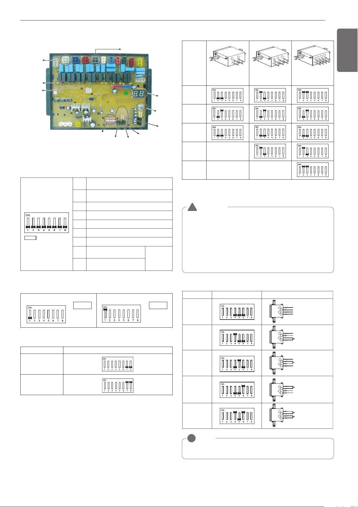
31
ENGLISH
Switch for setup of HR Unit
Main function of SW02M
1. Selection of the method for addressing valves of an HR unit
(Auto/Manual)
2. Setting the zoning control
SW02M
(Dip switch for setup of
the function of HR unit)
SW03M SW04M
SW01M/SW03M/SW04M
(Switch for manual valve
addressing)
SW01M
SW05M
(Switch for
addressing
HR unit)
7-SEG
#1 valve housing
#1 cooling valve
LED(green)
#1 heating valve
LED(red)
#4 valve housing
ON
S/W
Selection
No.1
Method for addressing valves of an HR
unit (Auto/Manual)
No.2 Model of HR unit
No.3 Model of HR unit
No.4 Valve group setting
No.5 Valve group setting
No.6 Valve group setting
No.7
Use only in factory pro-
duction (preset to “OFF”)
Zoning set-
ting (“ON”)
No.8
Use only in factory pro-
duction (preset to “OFF”)
SW02M
Auto Manual
Switch No.1 OnSwitch No.1 Off
DIP S/W setting
Normal control
Zoning control
HR UNIT PCB
4. Setting the Valve Group.
3. Selection of the model of the HR unit
* Each model is shipped with the switches No.2 and No.3 pre-adjusted
as above in the factory.
(For 2 branches)
PRHR021
(For 3 branches)
PRHR031
(For 4 branches)
PRHR041
Initial
Setting
1 branches
Connected
2 branches
Connected
3 branches
Connected
4 branches
Connected
1
2
3
1
2
1
3
2
4
WARNING
• If you want to use a PRHR031 for 2 branches HR unit after clos-
ing the 3rd pipes, set the dip switch for 2 branches HR unit.
• If you want to use a PRHR041 for 3 branches HR unit after clos-
ing the 4th pipes, set the dip switch for 3 branches HR unit.
• If you want to use a PRHR041 for 2 branches HR unit after clos-
ing the 3rd and 4th pipes, set the dip switch for 2 branches HR
unit.
• The unused port must be closed with a copper cap, not with a
plastic cap.
!
No.1, 2 Valve
/
No.3, 4 Valve
Control
No.3, 4 Valve
Control
DIP S/W setting
No.2, 3 Valve
Control
No.1, 2 Valve
Control
Not control
Example
Large capacity indoor unit
Large capacity indoor unit
1
2
3
4
Indoor Unit
Indoor Unit
Large capacity indoor unit
1
2
3
4
Indoor Unit
Indoor Unit
Large capacity indoor unit
1
2
3
4
Indoor Unit
Indoor Unit
Large capacity indoor unit
1
2
3
4
Indoor Unit
Indoor Unit
Indoor Unit
Indoor Unit
1
2
3
4
NOTE
!
If the large capacity indoor units are installed, below Y branch pipe should be
used.
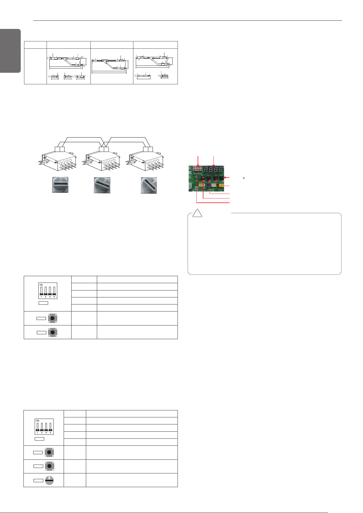
Automatic Addressing
The address of indoor units would be set by Automatic Addressing
- Wait for 3 minutes after supplying power.
(Master and Slave outside unit s, indoor units)
- Press RED button of the outside unit s for 5 seconds. (SW01C)
- A “88” is indicated on 7-segment LED of the outside unit PCB.
- For completing addressing, 2~7 minutes are required depending on
numbers of connected indoor units
-
Numbers of connected indoor units whose addressing is completed are
indicated for 30 seconds on 7-segment LED of the outside unit PCB
- Numbers of connected HR units whose addressing is completed are in-
dicated for 10 seconds on 7-segment LED of the outside unit PCB
- After completing addressing, address of each indoor unit is indicated
on the wired remote control display window. (CH01, CH02,
CH03, ……, CH06 : Indicated as numbers of connected indoor units)
[MAIN PCB]
DIP-SWITCH 7 - Segment
SW01C ( : confirm)
SW02C (ඔ : backward)
SW03C (ඖ : forward)
SW04C (
: cancel)
SW01D (reset)
CAUTION
• In replacement of the indoor unit PCB, always perform Automatic
addressing setting again (At that time, please check about using
Independent power module to any indoor unit.)
• If power supply is not applied to the indoor unit, operation error
occur.
• Automatic Addressing is only possible on the master Unit.
• Automatic Addressing has to be performed after 3 minutes to im-
prove communication.
!
Automatic pipe detection
1. Turn No.1 of SW02M of HR unit PCB off.
2. Confirm that the setting of No.2, 3 of SW02M corresponds with the
number of indoor units.
3. Reset the power of HR unit PCB
4. Master unit PCB DIP switch on : No.5
5. Select the mode using ‘▶’, ‘◀’ Button : “Idu” Push the ‘●’ button
6. Select the “Id 5” function using ‘▶’, ‘◀’ Button :“Ath” or “”Atc”
Push the ‘●’ button.
Outdoor temperature is over 15°C(59°F) : “Atc” Using (If it fail, use
“Ath”)
Outdoor temperature is below 15°C(59°F) : “Ath” Using (If it fail,
use “Atc”)
7. Select the mode using ‘▶’, ‘◀’ Button : “Idu” Push the ‘●’ button
8. Select the “Id 6” function using ‘▶’, ‘◀’ Button :“StA” Push the
‘●’ button
9. Operated after 88 is displayed on 7-SEG of the outside unit main
PCB.
10. Pipe detection proceed.
11. 5~30 minutes are required depending on the number of the indoor
units and outdoor temperature.
12. The number of the indoor units installed is displayed on 7-SEG of
the outside unit main PCB for about 1 minute
- For a HR unit, the number of the indoor units connected to each
HR unit is displayed.
- '200' is displayed in case of auto pipe detection error, and auto de-
tection is completed after '88' is disappeared.
* Auto pipe detection function : the function that sets connection re-
lationship automatically between the indoor unit and HR unit.
32
ENGLISH
ARBLB03321
Models
413(16-1/4)
390(15-11/32)
I.D19.05(3/4)
I.D19.05(3/4)
I.D19.05(3/4)
I.D15.88(5/8)
I.D12.7(1/2)
I.D12.7(1/2)
I.D12.7(1/2)
I.D12.7(1/2)
I.D12.7(1/2)
I.D12.7(1/2)
I.D12.7
(1/2)
74
(2-29/32)
70(2-3/4)
70(2-3/4)
I.D15.88(5/8)
I.D15.88(5/8)
I.D25.4(1)
I.D25.4(1)
I.D25.4(1)
O.D25.4(1)
80(3-5/32)
110(4-11/32) 110(4-11/32)
332(13-1/16)
321(12-5/8)
83
(3-9/32)
1
2
3
3
I.D19.05(3/4)
I.D19.05(3/4)
O.D19.05(3/4)
O.D19.05(3/4)
2
3 2
3
1 2
O.D15.88(5/8)
444(17-15/32)
421(16-9/16)
96
(3-25/32)
I.D15.88
(5/8)
I.D22.2(7/8)
I.D22.2(7/8)
I.D22.2(7/8)
I.D22.2(7/8)
I.D22.2(7/8)
I.D22.2(7/8)
O.D15.88(5/8)
I.D6.35(1/4)
I.D6.35(1/4)
I.D28.58(1-1/8)
I.D19.05(3/4)
I.D9.52(3/8)
I.D9.52(3/8)
I.D9.52(3/8)
I.D9.52(3/8)
Low Pressure Gas Pipe High Pressure Gas PipeLiquid pipe
Y branch pipe
[Unit : mm(inch)]
SW05M (Rotary S/W for addressing HR unit)
Must be set to '0' when installing only one HR unit.
When installing multiple HR units, address the HR units with sequen-
tially increasing numbers starting from '0'.
Ex) Installation of 3 HR units
1
2
3
4
1
2
3
4
1
2
3
4
AB AB AB
S/W No. Setup
No.1 Manual addressing of valve #1
No.2 Manual addressing of valve #2
No.3 Manual addressing of valve #3
No.4 Manual addressing of valve #4
SW03M
Increase in the digit of 10 of valve
address
SW04M
Increase in the last digit of valve ad-
dress
SW01M
SW03M
SW04M
2. Zoning setting
- Set the address of the valve of the HR unit to the central control
address of the connected indoor unit.
- SW01M : selection of the valve to address
SW03M : increase in the digit of 10 of valve address
SW04M : increase in the last digit of valve address
SW05M :Rotary S/W
- Prerequisite for manual valve addressing : central control address
of each indoor unit must be preset
differently at its wired remote control.
S/W No. Setup
No.1 Manual addressing of valve #1
No.2 Manual addressing of valve #2
No.3 Manual addressing of valve #3
No.4 Manual addressing of valve #4
SW03M
Increase in the digit of 10 of valve ad-
dress
SW04M Increase in the last digit of valve address
SW05M Manual addressing of zoning indoor units
SW01M
SW03M
SW04M
SW05M
0
SW01M/SW03M/SW04M (Dip S/W and tact S/W for
manual valve addressing)
1. Normal setting (Non-Zoning setting)
- Set the address of the valve of the HR unit to the central control
address of the connected indoor unit.
- SW01M: selection of the valve to address
SW03M: increase in the digit of 10 of valve address
SW04M: increase in the last digit of valve address
- Prerequisite for manual valve addressing : central control address
of each indoor unit must be preset differently at its wired remote
control.
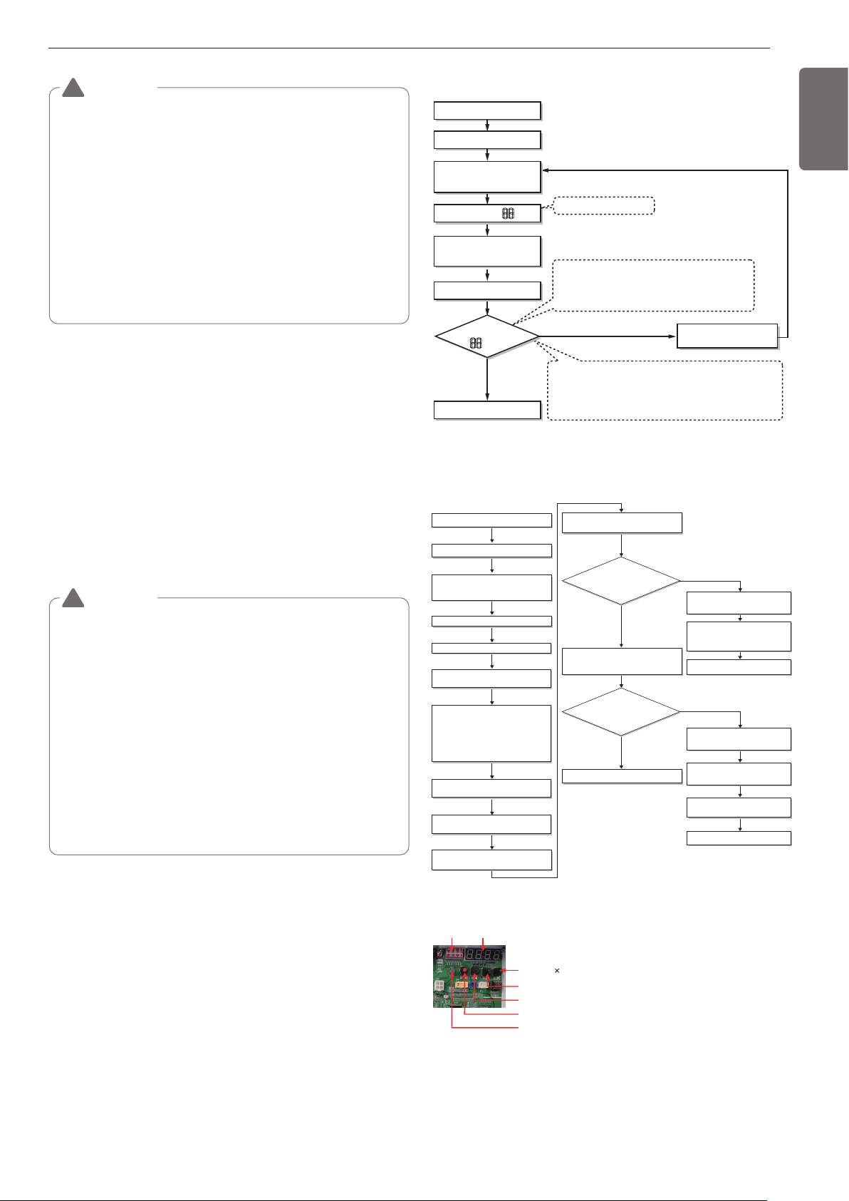
33
ENGLISH
Manual pipe detection
1. Enter the central control address into each indoor unit using its
wired remote control.
2. Turn No.1 of SW02M of HR unit PCB on.
3. Reset the power of HR unit PCB.
4. On the HR unit PCB, manually set address of each valve of the HR
unit to the central control address of the indoor unit connected to
the valve.
5. Reset the power of outside unit PCB.
6. The number of the indoor unit installed is displayed after about 5
minutes.
Ex) HR ➠ The number of the indoor
7. Reset the power of outside unit PCB, HR unit.
8. Manual pipe detection is completed
WARNING
1. Execute auto addressing and auto pipe detection again when-
ever the indoor PCB and HR unit PCB is replaced.
• Operation error occurs unless power is applied to the indoor
and HR units.
2. Error No.200 occurs if the number of connected indoor units and
that of scanned indoor units are different.
3. When auto pipe detection fails, complete it with manual pipe de-
tection (see Manual pipe detection).
4. When auto pipe detection addressing is completed normally,
manual pipe detection is not required.
5. If you want to do auto pipe detection again after auto pipe detec-
tion fails, do after reset of outside unit by all means.
6. During 5 minutes after pipe detection is completed, do not turn
off the main unit PCB to save the result of pipe detection auto-
matically.
!
WARNING
1. In case that central controller is not installed, remain the address
data after installer sets central control address as he wants
2. In case that central controller is installed, there would be central
control address in wired remote control of indoor unit.
3. In this case, set the HR unit manual pipe address according to
central control address of indoor unit.
4. Pipe which is not connected with indoor unit should be set differ-
ent address with pipe Connected with indoor unit.
(If addresses are piled up, corresponding valve is not working.
5. If you want to change the setting of manual pipe, you should do
it on HR unit PCB.
6. If an error occurred, it means that manual pipe setting is not
completed.
7. During 5 minutes after pipe detection is completed, do not turn
off the main unit PCB to save the result of pipe detection auto-
matically.
!
Flow chart of auto addressing for pipe detec-
tion
Completion of auto pipe detection
* It is possible to be generated mode changing noise of
heating and cooling which is normal.
There is no mode changing noise at normal operation.
Are the number
of indoor units connected to the
outside unit wiring and displayed
one equal?
Reset the power of HR unit PCB
Confirm that the setting of No.2, 3 of
SW02M corresponds with the number of
indoor units.
88' is displayed on 7-SEG of the outside
unit main PCB
Outside unit is operated for 5~60 minues.
The number of indoor units detected is
displayed for 30 seconds on the outside
unit PCB after outside unit stopped
Display error on outside unit PCB
Display error on HR unit PCB
Outside unit PCB : HR ơ HR unit
number ơ Valve number
HR unit : '200'
Check the HR unit and indoor unit
Pipe detection error occur after 30
seconds.
Check the installation of pipe of
outside, indoor, HR unit
Incompletion of auto pipe detection
Retry auto pipe detection after
checking trouble
Is the pipe
setting condition
satisfied during the operation of
indoor unit?
Confirmation of indoor unit address setting
Turn No.1 of SW02M of HR unit PCB off.
NO
NO
YES
YES
Master unit PCB DIP switch on : No.5
Select the mode using ‘ȯ’, ‘ȭ’ Button :
“Idu” Push the ‘Ɨ’ button
Select the mode using ‘ȯ’, ‘ȭ’ Button :
“Idu” Push the ‘Ɨ’ button
Select the “Id 6” function using ‘ȯ’, ‘ȭ’
Button :“StA” Push the ‘Ɨ’ button
Select the “Id 5” function using ‘ȯ’, ‘ȭ’
Button :“Ath” or ”Atc” Push the ‘Ɨ’ button.
Outdoor temperature is over 15°C(59°F) :
“Atc” Using (If it fail, use “Ath”)
Outdoor temperature is below 15°C(59°F) :
“Ath” Using (If it fail, use “Atc”)
DIP-SW01 7 - Segment
SW01C ( : confirm)
SW02C (ඔ : backward)
SW03C (ඖ : forward)
SW04C (
: cancel)
SW01D (reset)
The Procedure of Automatic Addressing
• Automatic addressing setting end
Numbers of indoor unit connection set whose
addressing is completed are indicated for 30seconds
on 7-segment LED after completing setting
Indoor address number is displayed on wired remote control or
indoor unit display window. It is not an error message, will
disappeared when on/off button is pressed on remote control
ex) Display of 01, 02, ..., 15 means connection of 15 indoor units
and Automatic addressing is completed normally.
Automatic addressing start
Waiting 3 minutes
Power On
Press RED Button for 5 sec.
(SW01C)
7-segment LED = 88
Don’t press RED Button
(SW01C)
Waiting about 2~7 minutes
7-segment LED
OK
YES
NO Check the connections
of communication cable
= 88
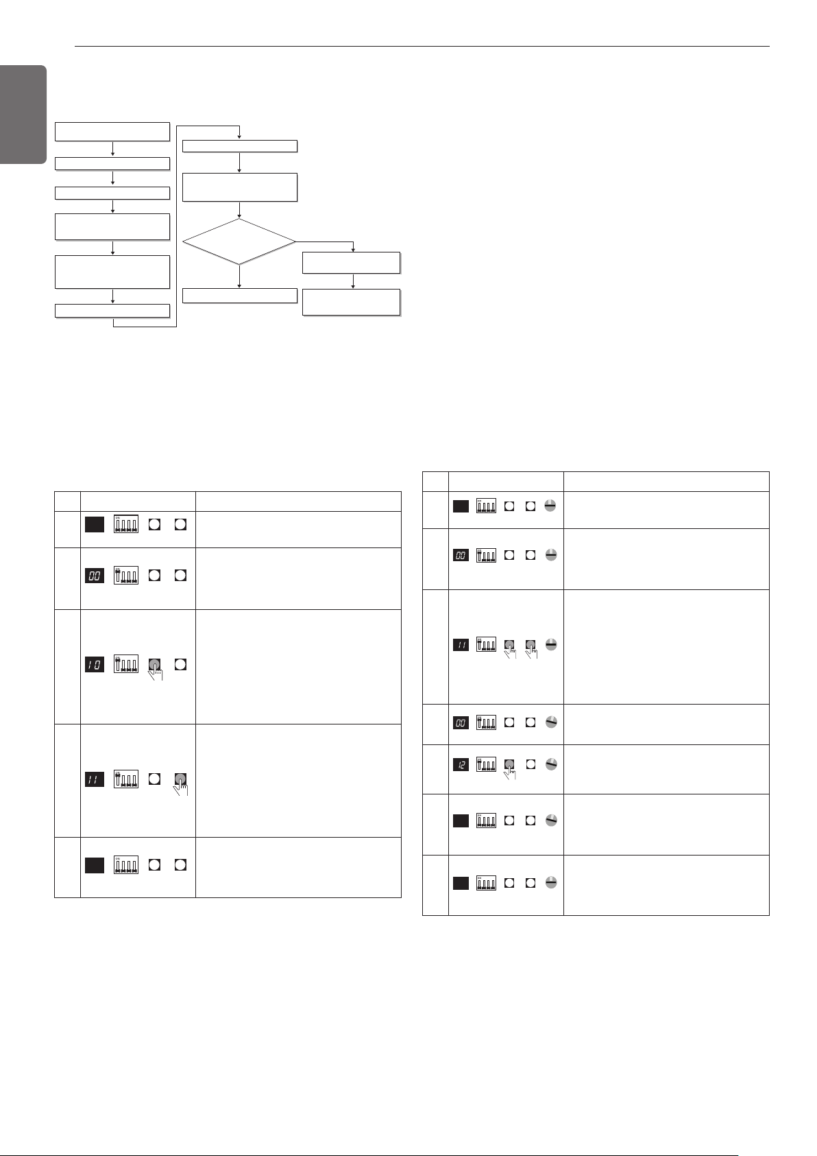
34
ENGLISH
- Above setup must be done for all HR unit valves.
- The valve that is not connected with any indoor unit should be ad-
dressed with any other number than used address numbers of the
valves connected with indoor units.
(The valves does not work if the address numbers are same.)
- Above setup must be done for all HR unit valves.
- The valve that is not connected with any indoor unit should be ad-
dressed with any other number than used address numbers of the
valves connected with indoor units.
(The valves does not work if the address numbers are same.)
Completion of manual pipe detection
Reset the power of HR unit PCB.
Enter the central control address into
each indoor unit using its wired remote
control.
On the HR unit PCB, manually set address
of each valve of the HR unit to the central
control address of the indoor unit
connected to the valve.
Reset the power of outside unit PCB.
Wait for about 5 minutes.
The number of the indoor units installed is
displayed.
Ex)HR The number of the indoor
Check the central control address of
indoor and HR unit.
Make sure that reset the outside unit
power when changing the central
control unit
Are the number
of indoor units connected to the
outside unit and displayed one
equal?
Execute in case of Auto pipe detection
failure
Turn No.1 of SW02M of HR unit PCB on.
NO
YES
No. Display and setup Setup and Contents
1
- Operation: None
- Display: None
2
- Operation: Turn dip S/W No.1 on to ad-
dress valve #1
- Display: Existing value saved in EEP-
ROM is displayed in 7-SEG.
3
- Operation: Set the digit of 10 to the
number in Group High data of the wired
remote control connected to the corre-
sponding indoor unit to the valve #1 by
pressing left tack S/W.
- Display: Digit increasing with the times
of pressing tack S/W is displayed in left
7-SEG
4
- Operation: Set the digit of 1 to the num-
ber in Group Low data of the wired re-
mote control connected to the
corresponding indoor unit to the valve
#1 by pressing right tack S/W.
- Display: Digit increasing with the times
of pressing tack S/W is displayed in
right 7-SEG
5
- Operation: Turn dip S/W No.1 off to
save the address of valve #1
- Display: "11" displayed in 7-SEG disap-
pears
7-SEG SW01M SW03M SW04M
7-SEG SW01M SW03M SW04M
7-SEG SW01M SW03M SW04M
7-SEG SW01M SW03M SW04M
7-SEG SW01M SW03M SW04M
Example of manual valve addressing (Zoning
setting)
(In case that an indoor unit of central control address "11" is connected
to a valve #1 of an HR unit)
Zoning control is connecting 2 or more indoor units at one pipe of HR
unit. In case of Zoning control, in order to set controls with multiple in-
door units connection uses the rotary switch. Namely, only the rotary
switch changes from same valve set condition and set indoor units
connection.
1. On dip switch of the corresponding valves and sets the rotary
switch at 0.
2. Setting the number with tact switch.
3. In case of addition of indoor units to same port, increases 1 with the
rotary switch and sets number with tact switch.
4. In case of checking the number which the corresponding valve is
stored, turn on dip switch and set the number of rotary switch.
5. Indoor units set available 7 per a port(rotary switch 0~6), in case of
setting above of 7 with rotary switch, it will display error.
6. Setting the rotary switch on original condition(HR unit number set
conditions) after all finishing a piping setting.
7. The rotary switch set value of above number of indoor units which is
connected with FF and prevents a malfunction.
(Example: The case where 3 indoor units is connected in piping 1,
sets from rotary switch 0,1,2 and 3,4,5 with FF set)
- Prerequisite for manual valve addressing: central control address of
each indoor unit must be preset differently at its wired remote con-
trol.
No. Display and setup Setup and Contents
1
- Operation: None
- Display: None
2
- Operation : Turn dip S/W No.1 on to ad-
dress valve #1
- Display : Existing value saved in EEP-
ROM is displayed in 7-SEG.
3
- Operation : Set the digit of 10(1) to the
number in Group High data of the wired
remote control connected to the corre-
sponding indoor unit to the valve #1 by
pressing left tack S/W.
- Display : Digit increasing with the times
of pressing tack S/W is displayed in left
7-SEG.
4
- Operation : SW05M : 1
- Display : Display former value.
5
- Operation : Setting No. using SW03M
and SW04M, SW05M : 1
- Display : Display setting value.
6
- Operation : Turn dip S/W No.1 off to
save the address of valve #1
- Display : "11" displayed in 7-SEG disap-
pears.
7
- Operation : Return valve of addressing
HR unit.
- Display : None
7-SEG SW01M SW03M SW04M
0
SW05M
7-SEG SW01M SW03M SW04M
SW05M
0
7-SEG SW01M SW03M SW04M
SW05M
0
1
7-SEG SW01M SW03M SW04M
SW05M
7-SEG SW01M SW03M SW04M
SW05M
1
7-SEG SW01M SW03M SW04M
SW05M
1
7-SEG SW01M SW03M SW04M
SW05M
0
Example of manual valve addressing (Non-
Zoning setting)
(In case that an indoor unit of central control address "11" is connected
to a valve #1 of an HR unit)
- Prerequisite for manual valve addressing: central control address of
each indoor unit must be preset differently at its wired remote con-
trol.
Flow chart of manual addressing for pipe de-
tection
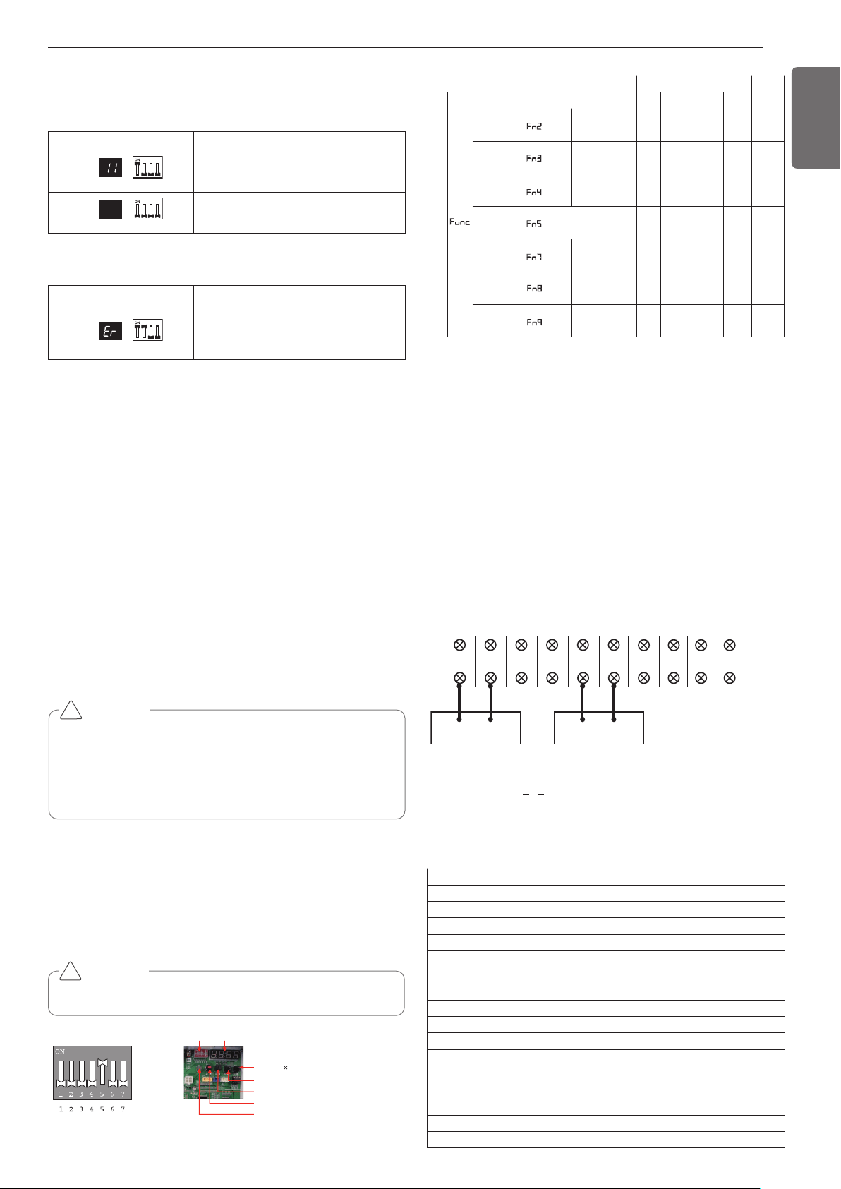
35
ENGLISH
No. Display and setup Setup and Contents
1
- Operation: Turn dip S/W No.1 on.
- Display: "11" is displayed in 7-SEG
2
- Operation: Turn dip S/W No.1 on.
- 7-SEG disappeared
7-SEG SW01M
7-SEG SW01M
No. Display and setup Setup and Contents
1
- Operation: more than 2 dip switches
turned on.
- Display: "Er" is displayed in 7-SEG
7-SEG SW01M
CAUTION
• Waiting for 80seconds after power on.
• The zoning information and Master IDU information remove from
EEPROM after Auto-addressing.
• If there is installed the central control, it is impossible setting of
Master IDU in zoning.
!
Setting method of Master indoor unit in zon-
ing
1. Master unit PCB DIP switch on: No.5
2. Select the mode using ‘▶’, ‘◀’ Button: "idu" Push the ‘●’ button
3. Select the "id 7" function using ‘▶’, ‘◀’ Push the ‘●’ button
4. select HR unit number and Pipe number as you want to change
- 7-Segment Display "[ x ] [ y ] [ _ ] [ _ ]"
[_]: Blank, [x]: HR unit number, [y]: Pipe number
- Change the HR unit number and Pipe number using ‘▶’, ‘◀’ Push
the ‘●’ button as you want to set
5. Select IDU number as you want
- 7-Segment Display "[ _ ] [ _ ] [ x ] [ y ]"
[_]: Blank, [x]: Indoor unit 10-digit number, [y]: Indoor unit 1-digit
number
- Set the master IDU number using ‘▶’, ‘◀’ Push the ‘●’ button
as you want to set
Identification of Manual Valve ID (Address)
Example of checking valve address
(In case that an indoor unit of central control address "11" is connected
to a valve #1 of an HR unit)
DIP-SW01 7 - Segment
SW01C ( : confirm)
SW02C (ඔ : backward)
SW03C (ඖ : forward)
SW04C (
: cancel)
SW01D (reset)
Dip switch setting
Setting the function
Select the mode/function/option/value using ‘▶’, ‘◀’ Button and con-
firm that using the ‘●’ button after dip switch No.5 is turned on.
CAUTION
It is only executed when all indoor units are off.
!
Group Number setting
Group Number setting for Indoor Units
- Confirm the power of whole system(Indoor Unit, Outside Unit) is
OFF, otherwise turn off.
- The communication cables connected to CEN.A and CEN.B terminal
should be connected to central control of Outside Unit with care for
their polarity (A-A, B-B ).
- Turn the whole system on.
- Set the group and Indoor Unit number with a wired remote control.
- To control several sets of Indoor Units into a group, set the group ID
from 0 to F for this purpose.
Outside Units (External PCB)
Example) Group number setting
1
st
number indicate the group number
2nd number point out indoor unit number
SODU.B SODU.A IDU.B IDU.A CEN.B CEN.A DRY1 DRY2 GND 12V
B(D) A(C) BA
1 F
Group Indoor unit
* Functions save in EEPROM will be kept continuously, though the
system power was reset.
To cancel the function you need to set OFF.
Mode Function Option Value Action
Remarks
Content
Display1
Content
Display2
Content Display3
Content Display4
Implement Display5
Installation
Geothermal
mode set-
ting
on
oFF
Selected
the option
- -
Change
the set
value
Blank
Save in
EEPROM
Sol. Valve
200 V out-
put
on
oFF
Selected
the option
- -
Change
the set
value
Blank
Save in
EEPROM
Variable
water flow
control
on
oFF
Selected
the option
- -
Change
the set
value
Blank
Save in
EEPROM
Outside unit
address
-
-
0~254
set
the
value
Change
the set
value
Blank
Save in
EEPROM
Target
pressure
adjusting
oFF
op1~
op4
Selected
the option
- -
Change
the set
value
Blank
Save in
EEPROM
Use Sump
Heater
on
oFF
Selected
the option
- -
Change
the set
value
Blank
Save in
EEPROM
IDU capacity
adjusting
on
oFF
Selected
the option
- -
Change
the set
value
Blank
Save in
EEPROM
Group recognizing the central controller
No.0 group (00~0F)
No.1 group (10~1F)
No.2 group (20~2F)
No.3 group (30~3F)
No.4 group (40~4F)
No.5 group (50~5F)
No.6 group (60~6F)
No.7 group (70~7F)
No.8 group (80~8F)
No.9 group (90~9F)
No. A group (A0~AF)
No. B group (B0~BF)
No. C group (C0~CF)
No. D group (D0~DF)
No. E group (E0~EF)
No. F group (F0~FF)
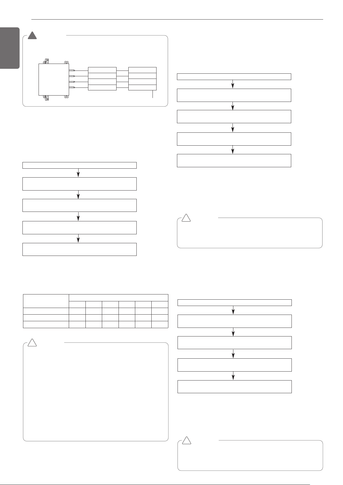
36
ENGLISH
WARNING
• Valve address and central control address of its corresponding in-
door unit should be set identical in manual addressing.
!
Valve (04)
EX)
Valve (03)
Valve (02)
Valve (01)
Indoor unit (04)
Indoor unit (03)
Indoor unit (02)
Indoor unit (01)
Central control address
HR unit
Geothermal mode setting
If you want to use the product with heat source water of the low tem-
perature such as ground heat, it is the function that enables the use of
ground heat mode.
How to set the mode
Mode setting
- ON: Set to operate in geothermal mode
- OFF: Set to operate in general mode
Turn on DIP switch No.5 of the master unit PCB
Use ‘▶‘ and ‘◀‘ button to mark “Func” in the 7 seg-
ment, and press ‘●‘ button.
Use ‘▶‘ and ‘◀‘ button to mark “Fn2” in the 7 seg-
ment, and press ‘●‘ button.
Use ‘ ‘ and ‘ ‘ button to select between “ON” and
“OFF” in the 7 segment, and press ‘●‘ button.
Decide the Geothermal mode according to
the setting mode.
CAUTION
• Request the function settings to the installation specialist during
the outside unit installation.
• When the function is not used, set it to OFF.
• Before changing the mode, make sure to check if the antifreeze
is added to the heat source water with appropriate ratio.
(If it is set to geothermal mode with inappropriate addition of an-
tifreeze or without antifreeze, there is a risk of product damage,
and we will not be responsible for such damage of the product.)
• When you add antifreeze, there may be increase of pressure dif-
ference in the heat source water system and product perform-
ance degradation.
• If it is in geothermal mode, add antifreeze according to the tem-
perature condition of at least -10°C(14°F).
(If the added amount is of -10°C(14°F) or more, it may cause
freeze and burst of the heat source water.)
!
Anti freeze type
Minimum temperature for anti freezing [°C(°F)]
0 -5(23) -10(14) -15(5) -20(-4) -25(-13)
Ethylene glycol (%) 0 12(54) 20(68) 30(86) - -
Propylene glycol (%) 0 17(63) 25(77) 33(91) - -
Methanol (%) 0 6(43) 12(54) 16(61) 24(75) 30(86)
CAUTION
• Request the function settings to the installation specialist during
the outside unit installation.
• When the function is not used, set it to OFF.
!
Mode setting
- ON: Set to control the heat source water pipe Solenoid Valve from
the product.
- OFF: Set not to control the heat source water pipe Solenoid Valve
from the product.
Turn on DIP switch No.5 of the master unit PCB
Use ‘▶‘ and ‘◀‘ button to mark “Func” in the 7 seg-
ment, and press ‘●‘ button.
Use ‘▶‘ and ‘◀‘ button to mark “Fn3” in the 7 seg-
ment, and press ‘●‘ button.
Use ‘▶‘ and ‘◀‘ button to select between “ON” and
“OFF” in the 7 segment, and press ‘●‘ button.
Decide Sol. Valve 220V control
according to the set mode.
CAUTION
• Request the function settings to the installation specialist during
the outside unit installation.
• When the function is not used, set it to OFF.
!
Variable water flow control
It is the function to select when you want to install Variable water flow
control kit and control it from the product.
How to set the mode
Mode setting
- ON: Set to control the variable water flow control valve from the prod-
uct
- OFF: Set not to control the variable water flow control valve from the
product
Turn on DIP switch No.5 of the master unit PCB
Use ‘▶‘ and ‘◀‘ button to mark “Func” in the 7 seg-
ment, and press ‘●‘ button.
Use ‘▶‘ and ‘◀‘ button to mark “Fn4” in the 7 seg-
ment, and press ‘●‘ button.
Use ‘▶‘ and ‘◀‘ button to select between “ON” and
“OFF” in the 7 segment, and press ‘●‘ button.
Decide the Variable water flow control mode
according to the set mode.
Sol. Valve 220V output
It is the function to select 220V output when you want solenoid valve
control.
How to set the mode
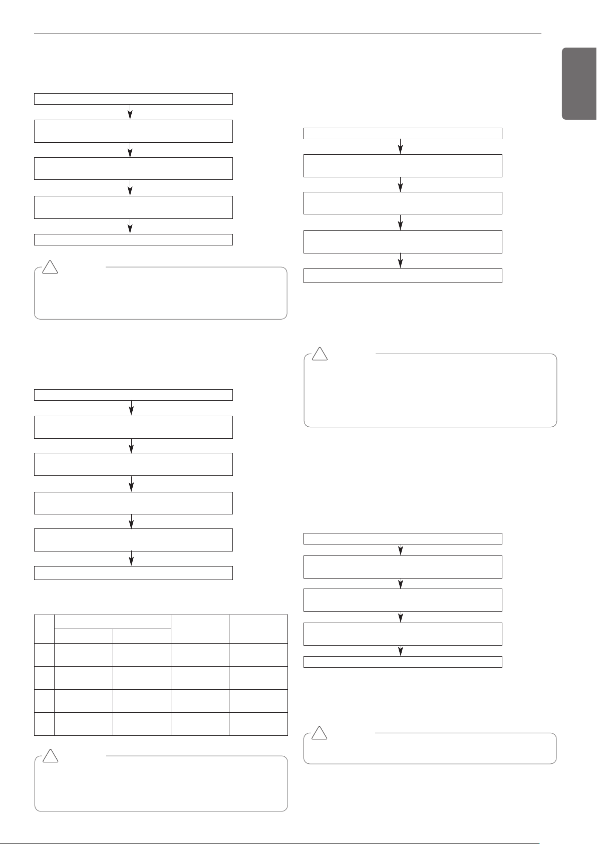
37
ENGLISH
CAUTION
• Request the function settings to the installation specialist during
the outside unit installation.
• When the function is not used, set it to OFF.
• If the temperature of the outside unit installation place is 0°C or
less, we recommend the connection and usage of Sump Heater.
!
Use Sump Heater
It is the function to select when you want to connect and use Sump
Heater.
How to set the mode
Mode setting
- ON: Set to control the Sump Heater from the product
- OFF: Set not to control the Sump Heater from the product
Mode setting
- ON: Set to control the Low capacity mode
- OFF: Set not to control
Turn on DIP switch No.5 of the master unit PCB
Use ‘▶‘ and ‘◀‘ button to mark “Func” in the 7 seg-
ment, and press ‘●‘ button.
Use ‘▶‘ and ‘◀‘ button to mark “Fn8” in the 7 seg-
ment, and press ‘●‘ button.
Use ‘▶‘ and ‘◀‘ button to select between “ON” and
“OFF” in the 7 segment, and press ‘●‘ button.
Decide Sump Heater control according to the set mode.
IDU capacity adjusting
If the operation of indoor unit is more than 130%, the air flow is oper-
ated as low in the all indoor units.
How to set the mode
Turn on DIP switch No.5 of the master unit PCB
Use ‘▶‘ and ‘◀‘ button to mark “Func” in the 7 seg-
ment, and press ‘●‘ button.
Use ‘▶‘ and ‘◀‘ button to mark “Fn9” in the 7 seg-
ment, and press ‘●‘ button.
Use ‘▶‘ and ‘◀‘ button to select between “ON” and
“OFF” in the 7 segment, and press ‘●‘ button.
CAUTION
• Ask an authorized technician to setting a function.
!
IDU capacity adjusting mode is set
Setting the outside unit address
How to set the mode
Turn on DIP switch No.5 of the master unit PCB
Use ‘▶‘ and ‘◀‘ button to mark “Func” in the 7 seg-
ment, and press ‘●‘ button.
Use ‘▶‘ and ‘◀‘ button to mark “Fn5” in the 7 seg-
ment, and press ‘●‘ button.
Use ‘▶‘ and ‘◀‘ button to select one among “0” ~
“254” in the 7 segment, and press ‘●‘ button.
Outside unit address is set.
CAUTION
• Request the function settings to the installation specialist during
the outside unit installation.
• If use a function, first install a Central controller.
!
Target pressure adjusting
How to set the mode
Turn on DIP switch No.5 of the master unit PCB
Use ‘▶‘ and ‘◀‘ button to mark “Func” in the 7 seg-
ment, and press ‘●‘ button.
Use ‘▶‘ and ‘◀‘ button to mark “Fn7” in the 7 seg-
ment, and press ‘●‘ button.
Select the Option using ‘▶’, ‘◀’ Button :
“op1” ~ “op4” Push the ‘●’ button
Decide target pressure according to the set mode.
Select the Option using ‘▶’, ‘◀’ Button :
“HEAT” , “COOL” Push the ‘●’ button
CAUTION
• Ask an authorized technician to setting a function.
• If do not use a function, set an off-mode.
• Change a power consumption or capacity.
!
Setting
mod
e
Purpose
Condensing
temperature
variation
Evaporating
temperature
variation
“Heat” “Cool”
op1
Increase
capacity
Increase
capacity
-3°C(26.6°F) +2°C(35.6°F)
op2
Decrease power
consumption
Increase
capacity
-1.5°C(29.3°F) -2°C(28.4°F)
op3
Decrease power
consumption
Decrease power
consumption
+2.5°C(36.5°F) -4°C(24.8°F)
op4
Decrease power
consumption
Decrease power
consumption
+4.5°C(40.1°F) -6°C(21.2°F)
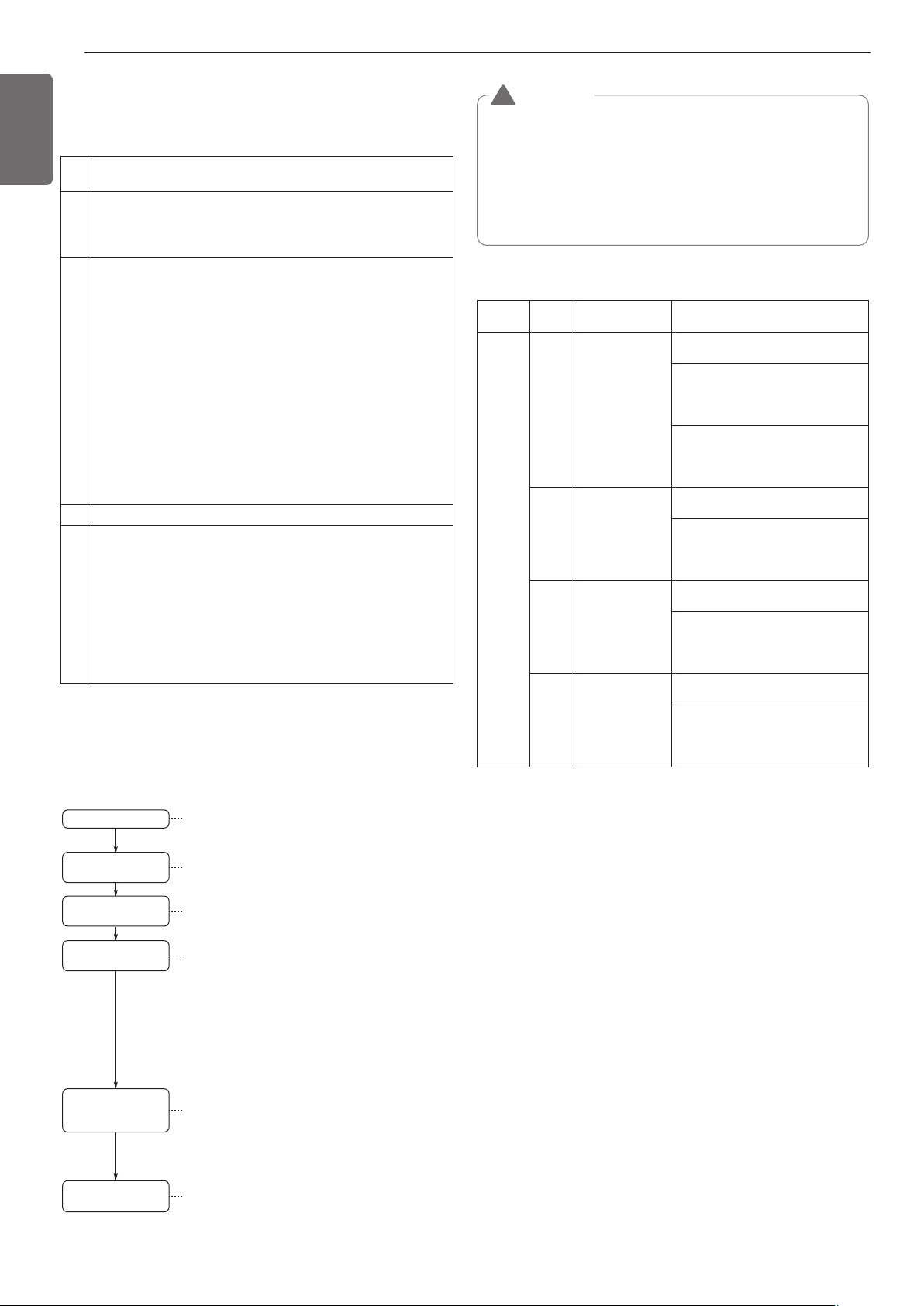
38
ENGLISH
WARNING
• Always check whether the water supply is flowing smoothly
before the test run. (If sufficient amount of water is not flow-
ing, it can burn the product.)
• During the initial test run after installing the product, leaving
the product for more than 3 days or after replacing the com-
pressor, power must be connected 6 hours prior to the opera-
tion to heat the compressor heater. (If the product is not
heated sufficiently, it can burn the product.)
!
How to Cope with Abnormal Test Run
Maintenance of plate type heat exchanger
Item
Phenom-
enon
Cause Checkpoint and resolution
Whether
heat
water is
supplied
CH24
When connecting
the flow switch,
heat-sourced
water doesn’t
flow or the
amount of its flow
lacks due to the
checked error re-
lated to heat-
sourced water.
Check whether the heat source water
supply pump is operating.
Check whether the heat source water
supply pipe is clogged.
(Clean strainer, valve locked, valve
issue, air trapped etc.)
Check whether the flow switch is nor-
mal condition.
(Flow switch problem, arbitrary con-
trol, disconnection etc.)
CH32
Heat water not
supplied or flow
rate is insufficient
Check whether heat source water
supply pump is operating.
Check whether the heat source water
supply pipe is clogged.
(Clean strainer, valve locked, valve
issue, air trapped etc.)
CH34
Heat water not
supplied or flow
rate is insuffi-
cient(During Cool-
ing)
Check whether heat source water
supply pump is operating.
Check whether the heat source water
supply pipe is clogged.
(Clean strainer, valve locked, valve
issue, air trapped etc.)
CH180
Heat water not
supplied or flow
rate is insufficient
(During heating)
Check whether heat source water
supply pump is operating.
Check whether the heat source water
supply pipe is clogged.
(Clean strainer, valve locked, valve
issue, air trapped etc.)
❈ When CH24 or CH180 error occurs during the test operation of the
heater, the inside of the panel heat exchanger may be partially
frozen and therefore, be sure to get rid of its cause and then, re-op-
erate the device.
(The root cause of partial freezing: The lack of flow of heat-sourced
water, suspension of water, lack of cooling medium, infiltration of
foreign substance inside of panel heat exchanger )
Water supply system test run
Before executing the test run for the product, you must first test the
heat source water system.
The test run for the product must be executed after checking the flow
rate and temperature of the heat source water supplied.
Equipment design
Execute the
product test run
Water pipe system
installation
Water supply pipe
and product connection
Water supply
system test run
Judging whether there
is any problem with
the water supply
Design the system including cooling tower, boiler, pump etc.
- Check the equipment capacity (Water volume, temperature
control range).
Connect the water pipe to the inlet/outlet of the product so
that the water can be supplied to the product.
Execute water supply system test run
- The product does not operate but the pump and water
supply equipment will operate to flow the Heat source
water to the heat exchanger on the product side.
- Flow the water to all water piping system to clean any alien
particles inside the pipes and execute an air purge to
remove an air within the pipes to make the water supply
smoother.
- Clean all the strainers of water pipe including around
outside units.
Execute the test of water supply system without operating
the product.
- Check whether outside unit inlet/outlet flow rate complies
to the product specification. Standard Water volume is
96LPM based on 10HP and 196LPM based on 20HP.
- Check the water supply temperature. whether is OK
After checking the normal condition of the water supply,
execute the test run of the product.
To prevent the freezing of the heat exchanger when the
refrigerant is discharged with the water supply blocked,
discharge the refrigerant after draining out around the
outside unit.
Install the water pipe
1
Check whether the air is completely removed and the water sup-
ply is flowing smoothly.
2
Check whether there is any refrigerant leakage of any disconnected
or loose communication or power wire, or use the electric wiring dia-
gram to check the wiring connection condition. Check whether the
power and communication wire are connected.
3
Check whether the power cable R, S, T and N are correctly con-
nected. Check the insulation resistance with the DB mega tester
device (DC 500V) between the power terminal block and ground-
ing, and check whether it is 2.0MΩ or above when measured.
If the resistance is 2.0MΩ or less, do not operate the product.
Precaution)
- Never check the insulation resistance for the terminal control
board. (The control board can be damaged.)
-
If you leave the system turned off right after the installation or for a
long period of time, the refrigerant gets accumulated within the
compressor and the insulation resistance reduces to less than 2
MΩ. When the insulation resistance is 2 MΩ or less, turn on the
power and let the electricity be supplied to the crank case heater of
the compressor and let the refrigerant including the oil inside the
compressor to evaporate. Then the insulation resistance value will
increase to more than 2.0 MΩ.
4 Check whether the liquid and gas pipes are open.
5
Precaution when blocking the water cooling type Multi V main power
- While using the product (Air conditioning season/Heating season), al-
ways connect the main power of the outside unit.
-
During the test run operation after installing the product or during the oper-
ation after blocking the outside unit main power (Power outage etc.), you
must always connect the power 6 hours prior to heating the crank case
heater. If the crank case is not preheated for more than 6 hours with the
electric heater, it can cause a burn on the compressor.
(Heating the bottom part of the compressor with the crank case heater is
to evaporate the refrigerant included in the oil inside the compressor.)
As the scales are created in the panel heat exchanger, its efficiency
may decrease or damage may occur due to winter-sowing due to the
decrease in its flow.
Due to this reason, regular maintenance is necessary so that the scales
shouldn't be created.
1 Before the season of use, check below points.(Once a year)
1) Inspection on water quality to check if this is within the standard
condition.
2) Clean the strainer.
3) Check if the flow is appropriate.
4) Check if the operation environment is appropriate.(Pressure,
flow, output temperature)
2 Below procedure should be abided by in order to clean the panel
heat exchanger. (Once every 5 years)
1) Check if the service port is equipped with the water pipe in order
to clean the chemical solution.
5% diluted formic acid, citric acid, oxalic acid, acetate acid, phos-
phoric acid and etc. are appropriate for the chemical solution for
wiping out the scales.(Hydrochloric acid, sulphuric acid, nitric acid
and etc. shouldn't be used due to its corrosion.)
TEST RUN
Precaution before test run
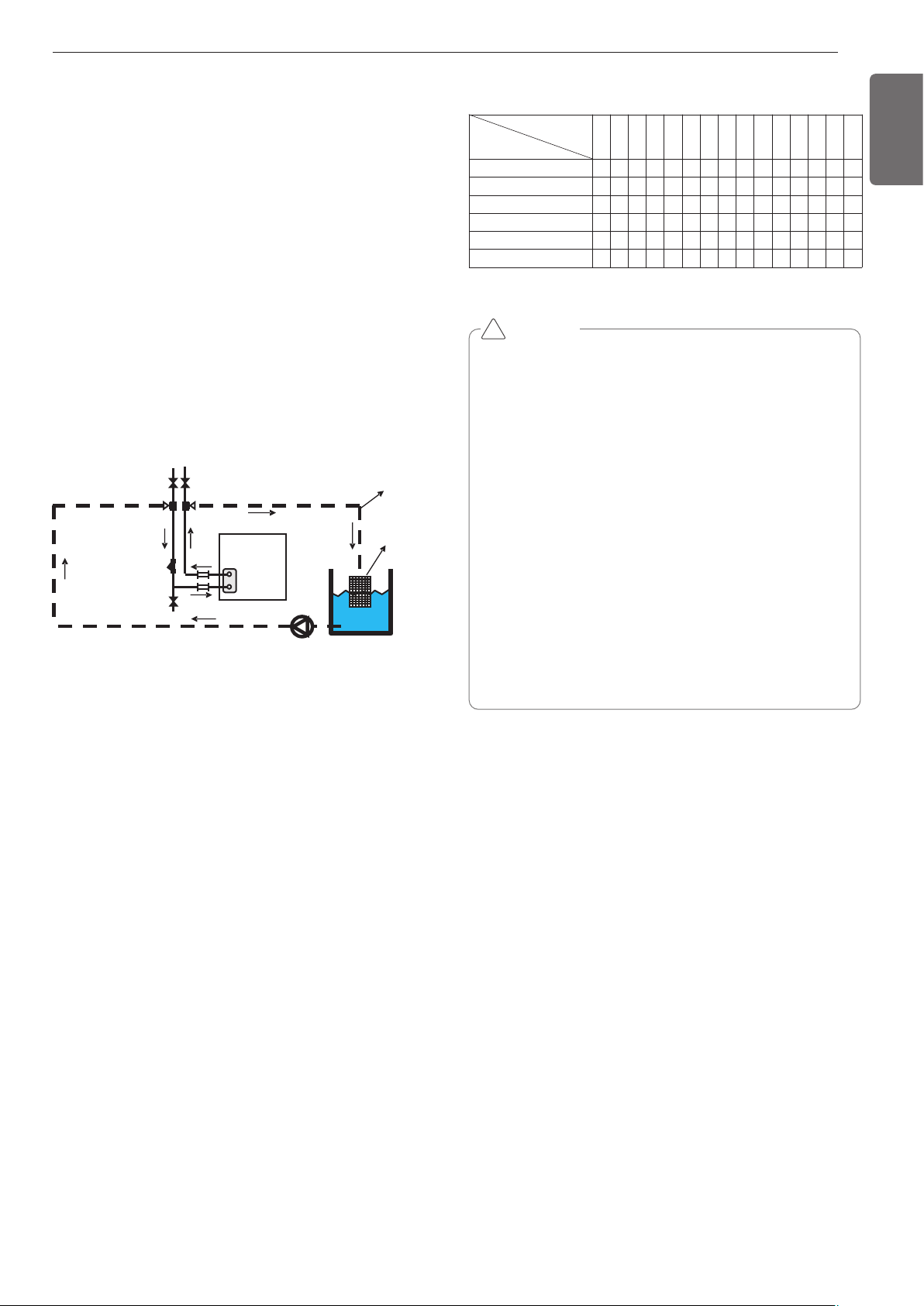
39
ENGLISH
Daily check/management
1
Water quality control
The plate type heat exchanger is not structured to be disassem-
bled, cleaned or replaced with parts. To prevent corrosion or scaling
on the plate type heat exchanger, special care must be taken to
control the water quality. Water quality must satisfy the minimum
criteria of the reference water quality items. When anti-corrosion
agent or corrosion inhibitor is added, the substance must not have
any corrosive effect on stainless steel and copper. Even if the circu-
lating water is not contaminated by the external air, it is recom-
mended to empty the water flowing in the pipe and to resupply the
water.
2
Flow rate control
If the flow rate is insufficient, it can cause freezing on the plate type
heat exchanger. Check whether the strainer is clogged or whether
the pipe is filled with air and then check the temperature and pres-
sure difference of the inlet and outlet pipe to check whether the
flow rate is insufficient. If the temperature and pressure difference
is above the appropriate level, it means that the flow rate is re-
duced. In this case, the operation must immediately be stopped
and re-operated when the root cause is resolved. (*If air is trapped
in the pipe, the air must be purged. Air inside the water pipe inter-
feres with the circulation of the heat water supply and can cause in-
sufficient flow rate or freezing.)
3
Brine density management
When using the brine (Anti-freeze) in the heat water supply, desig-
nated type and density must be used. Calcium chloride brine can
cause corrosion on the plate type heat exchanger and must not be
used. If the anti-freeze liquid is left as is, it absorbs the moisture
from the air to cause a drop in the density, leading to freezing of
plate type heat exchanger. Therefore minimize the contact surface
with the atmosphere and periodically measure the density of the
brine to supplement the brine as needed to maintain the density.
Maintenance/Repair checklist
123456789101112131415
●●●●●●●●●●●●●●●
●●●
●●●●●●●●●●●●●●●
●●●●●●●●●●●●●●●
●●
●●●●●●●●●●●●●●●
Period (Year)
Checkpoint
Product operating condition
Heat exchanger cleaning (Wash)
Strainer cleaning
Water quality check
Refrigerant leakage check
Indoor unit filter cleaning
CAUTION
• The above checklist is set based on the minimum period and
more frequent checking can be required depending on the oper-
ating condition/water quality condition.
• When cleaning the heat exchanger, make sure to take parts out
or lock the value so that chemical detergent does not penetrate
into the pressure gauge etc.
• When cleaning the heat exchanger, check the connecting part of
the water pipes prior to cleaning so that the chemical detergent
does not leak.
• After sufficiently mixing the chemical detergent with water, start
cleaning.
• Cleaning the heat exchanger is easier at the initial stage and be-
comes difficult after the scaling has accumulated.
• In areas where the water quality is poor, cleaning is required pe-
riodically.
Because chemical detergent has strong acidity, it must be
washed off thoroughly with water.
• To check whether it is cleaned well inside, remove the hose and
check the inside.
• Purge the air to remove any air inside the water pipe.
• After checking, always check whether the heat water supply is
flowing normally flowing before operating the product.
!
2) Be sure to check if the gate valve of inflow/outflow pipe and the
valve for outflow pipe are properly closed when cleaning.
3) Connect the water pipe for cleaning with the chemical solvent
through the service plug of the pipe and fill up the panel heat ex-
changer with 50°C~60°C(122°F~140°F) of cleaning solvent and
circulate it with the pump for 2~5 hours. The circulation time
may depend on the temperature of the cleaning solvent or the
creation of the scales. Therefore, observe change in the color of
the chemical solvent to set the circulation time for removing the
scales.
4) After the circulation of the solvent, extract the solvent inside of
the panel heat exchanger and fill up 1~2% of NaOH or NaHCO3
and then, circulate it for 15~20 minutes to neutralize the heat ex-
changer.
5) Once the neutralization is completed, clean the inside of the
panel heat exchanger with clean water.
Measure the water Ph to check if the chemical solvent is prop-
erly removed or not.
6) When using a different kind of chemical solvent in the market, be
sure to check if there is any corrosive action to stainless or cop-
per in advance or not.
7) For details on the cleaning chemical solvent, be sure to consult
the specialists of the related corporation.
3 After cleaning, operate the device to see if it works properly once
again.
Gate valve(locked)
Service plug
Strainer
Outflow water
valve(locked)
Gate valve(locked)
Water-cooling
type Multi V
Hose
Pump
[Cleaning the panel heat exchanger]
Screening ne
t
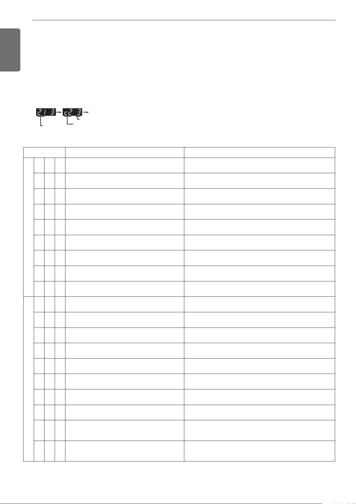
40
ENGLISH
Self-Diagnosis Function
Error Indicator
- This function indicates types of failure in self-diagnosis and occurrence of failure for air condition.
- Error mark is displayed on display window of indoor units and wired remote controller, and 7-segment LED of outside unit control board as
shown in the table.
- If more than two troubles occur simultaneously, lower number of error code is first displayed.
- After error occurrence, if error is released, error LED is also released simultaneously.
Error Display
1st,2nd,3rd LED of 7-segment indicates error number, 4th LED indicates unit number.(* = 1: Master, 2: Slave 1, 3: Slave 2)
Ex)
* Refer to the DX-Venitilation manual for DX-Venitilation error code.
Error No. of Compressor
Error No.
Error No. of Unit
Repeat
Display Title Cause of Error
Indoor unit related error
0 1 -
0 2 -
0 3 -
0 4 -
0 5 -
0 6 -
0 9 -
1 0 -
1 7 -
Outside unit related error
2 1 *
2 2 *
2 3 *
2 4 *
2 5 *
26*
28*
29*
32*
34*
Air temperature sensor of indoor unit
Inlet pipe temperature sensor of indoor unit
Communication error : wired remote controller in-
door unit
Drain pump
Communication error : outside unit indoor unit
Outlet pipe temperature sensor of indoor unit
Indoor EEPROM Error
Poor fan motor operation
Inlet Air temperature sensor of FAU
Master outside unit inverter compressor IGBT Fault
Inverter Board Input Over Current(RMS) of Master
outside Unit
Master outside unit inverter compressor DC link
under-voltage
Master outside unit high pressure switch
Master outside unit input voltage over-
voltage/under-voltage
Master outside unit inverter compressor operation
failure error
Master outside unit inverter DC link over-voltage
error
Master outside unit inverter compressor overcurrent
Master outside unit inverter compressordischarge
temperature over-rise
Master outside unit high pressure over-rise
Air temperature sensor of indoor unit is open or short
Inlet pipe temperature sensor of indoor unit is open or short
Failing to receive wired remote controller signal in indoor unit PCB
Malfunction of drain pump
Failing to receive outside unit signal in indoor unit PCB
Outlet pipe temperature sensor of indoor unit is open or short
In case when the serial number marked on EEPROM of Indoor unit
is 0 or FFFFFF
Disconnecting the fan motor connector/Failure of indoor fan motor
lock
Air temperature sensor of indoor unit is open or short
Master outside unit inverter compressor drive IPM error
Master Outside Unit Inverter Board Input Current excess (RMS)
DC voltage is not charged after master outside unit operating relay
is turned on
Compressor maintenance by master outside unit high pressure switch
Flow rate insufficiency or flow switch trouble of master outside unit
Master outside unit input voltage over-voltage or under-voltage
Initial operation failure due to master outside unit inverter compres-
sor error
Compressor turned Off due to master outside unit inverter DC volt-
age over-charge
Master outside unit inverter compressor error or operating compo-
nent (IGBT) error operation
Compressor turned off due to master outside unit inverter compres-
sor discharge temperature over-rise Flow rate insufficiency or flow
switch trouble of master outside unit
Compressor turned off due to master outside unit high pressure
over-rise Flow rate insufficiency or flow switch trouble of master
outside unit
41
ENGLISH
1 0 4*
1 1 3*
1 1 5*
116*
Display Title Cause of Error
Outside unit related error
3 5 *
3 6 *
3 9 *
4 0 *
4 1 *
4 2 *
4 3 *
4 4 *
4 6 *
4 9 *
5 0 *
5 1 *
5 2 *
5 3 *
5 7 *
5 9 *
6 0 *
6 2 *
6 5 *
7 1 *
8 6 *
88*
Master outside unit low pressure over-drop.
Master Outside Unit Low Compression Ratio Lim-
ited
Master Outside unit Communication error between
Master outside unit PFC and inverter board
Master outside unit inverter compressor CT sensor
error
Master outside unit inverter compressor discharge
temperature sensor error
Master Outside Unit Low Pressure Sensor Fault
Master Outside Unit High Pressure Sensor Fault
Master Outside unit air temperature sensor error
Master outside unit suction temperature sensor
error
Master outside unit IGBT temperature sensor error
Master outside unit 3 phase power missing
Over-capacity (Indoor unit capacity sum is exces-
sive) connection
Communication error: inverter PCB ➔ Main PCB
Communication error: indoor unit ➔ Main PCB of
Outside Unit
Communication error: Main PCB ➔ inverter PCB
Wrong setting between master and slave outside
unit
Master outside unit inverter PCB EEPROM error
Master outside unit inverter IGBT over-rise error
Master outside unit inverter IGBT temperature sen-
sor error
PFC CT Sensor Error of Master Outside Unit
Master outside unit master PCB EEPROM error
PFC PCB EEPROM error
Compressor turned off due to master outside unit low pressure
overdrop.
Master Outside Unit stayed under low Compression limit for 3
minutes
Master Outside unit inverter compressor current detection (CT) sen-
sor disconnection or short circuit
Master outside unit inverter compressor current detection (CT) sen-
sor disconnection or short circuit
Master outside unit inverter compressor discharge temperature
sensor disconnection or short circuit
Master Outside Unit Low Pressure Sensor open or short
Master Outside Unit High Pressure Sensor open or short
Master Outside unit air temperature sensor disconnection or short
circuit
Master outside unit suction temperature sensor disconnection or
short circuit
Master out side unit IGBT temperature sensor disconnection or
short circuit
Master outside unit power line phase missing
Excessive connection of indoor unit connection display value (Differ-
ent from outside unit)
When the inverter controller signal is not received from the master
outside unit inverter controller
When the indoor unit control signal is not received from the master
Outside unit controller
Failing to receive inverter contoroller signal at Master Outside Unit
controller
When geothermal mode setting is different(Fn 2 setting)
Master outside unit inverter PCB EEPROM ACCESS error
Master outside unit inverter IGBT when the temperature rises
above 110 °C
Master outside unit inverter IGBT temperature sensor disconnec-
tion or short circuit
Master Outside Unit PFC CT Sensor open or short
Communication error between master outside unit master MICOM
andEEPROM or EEPROM missing
Communication error between master outside unit master PFC and
EEPROM or EEPROM missing
Communication Error Between Master Outside Unit
and Other Outside Unit
Master Outside Unit Liquid pipe Temperature Sen-
sor Error
Master Outside Unit Subcooling Outlet Temperature
Sensor Error
Master Outside Unit Oil Level Sensor Error
Failing to receive Slave Unit signal at main PCB of Master Outside
Unit
Liquid pipe temperature sensor of Master Outside Unit is open or
short
Master Outside Unit Subcooling Outlet Temperature Sensor open
or short
Oil Level Sensor of Master Outside Unit is open or short
Outside unit related error
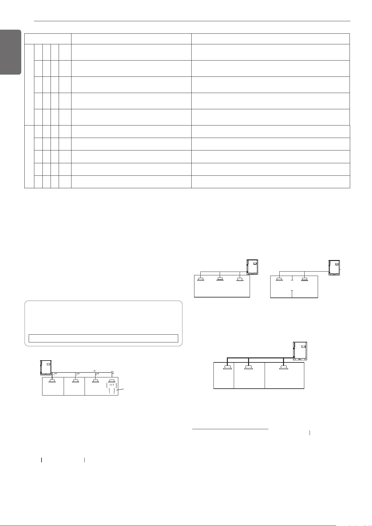
42
ENGLISH
HR Unit related error
2 0 01 Searching pipe Error Failure of automatic addressing of valves
2 0 1 #h HR unit1 Liqiud sensor error Liquid pipe sensor of HR unit open or short
2 0 2 #h HR unit1 Sub Cooling Pipe sensor error Sub Cooling Pipe In sensor of HR unit open or short
2 0 3 #h HR unit1 Sub Cooling Pipe Out sensor error Sub Cooling Pipe Out sensor of HR unit. open or short
2 0 4 #h Communication error Failing to receive HR unit signal at outside unit
Display Title Cause of Error
Outside unit related error
145 *
151 *
180 *
181 *
182 *
Master outside unit Main Board - External Board
communication Error
Failure of operation mode conversion at Master
Outside Unit
Plate type heat exchanger freeze prevention
Water temperature sensor error
Communication error between MICOMs of exter-
nal pcb
Master outside unit Main Board - External Board communication
Error
Failure of operation mode conversion at Master Outside Unit
Plate type heat exchanger freeze prevention error
Water temperature sensor open/short
Communication error between main MICOM and sub MICOM of
external pcb
Checking procedure of limiting concentration
Check limiting concentration along following steps and take appropri-
ate measure depending on the situation.
Calculate amount of all the replenished refrigerant (kg) per each refrig-
erant system.
Calculate minimum room capacity
Calculate room capacity by regarding a portion as one room or the
smaller room.
- With partition and with opening
which serve as passage of air to
adjoining room
- Without partition
Limiting concentration is the limit of Freon gas concentration
where immediate measures can be taken without hurting human
body when refrigerant leaks in the air. The limiting concentration
shall be described in the unit of Kg/m
3
(lbs/ft
3
) (Freon gas weight
per unit air volume) for facilitating calculation.
Limiting concentration: 0.44kg/m
3
(0.028lbs/ft
3
)(R410A)
Amount of additional
replenished refrigerant
Total amount of replenished
refrigerant in refrigerant
facility (kg)
+
=
Note : In case one refrigerant facility is
divided into 2 or more refrigerant
systems and each system is
independent, amount of replenished
refrigerant of each system shall be
adopted.
Amount of replenished
refrigerant per one outside
unit system
Amount of replenished
refrigerant at factory shipment
Amount of additionally
replenished refrigerant
depending on piping
length or piping
diameter at customer
Outside unit
Indoor unit
Outside unit
Indoor unit
Opening
Partition
In the case of opening
without door , or 0.15
% or more openings
(to floor space) both
above and below door)
Outside unit
(No.1 system)
Flow of
refrigerant
Indoor unit
Room where refrigerant leaks
(Refrigerant of the whole No.1
system flows out.)
The installer and system specialist shall secure safety against leakage
according to local regulations or standards.
The following standards may be applicable if local regulations are not
available.
Introduction
Though the R410A refrigerant is harmless and incombustible itself ,
the room to equip the air conditioner should be large to such an extent
that the refrigerant gas will not exceed the limiting concentration even
if the refrigerant gas leaks in the room.
Limiting concentration
- With partition and without opening which serve as passage of air to
adjoining room
Calculate refrigerant concentration
Total amount of replenishedrefrigerant
in refrigerant facility [kg(lbs)]
Capacity of smallest room
whereindoor unit is installed [m
3
(ft
3
)]
- In case the result of calculation exceeds the limiting concentration, perform
the same calculations by shifting to the second smallest, and the third small-
est rooms until at last the result is below the limiting concentration.
= Refrigerant concentration[Kg/m
3
(lbs/ft
3
)]
(R410A)
Outside unit
Indoor unit
Smallest
room
CAUTION FOR REFRIGERANT LEAK
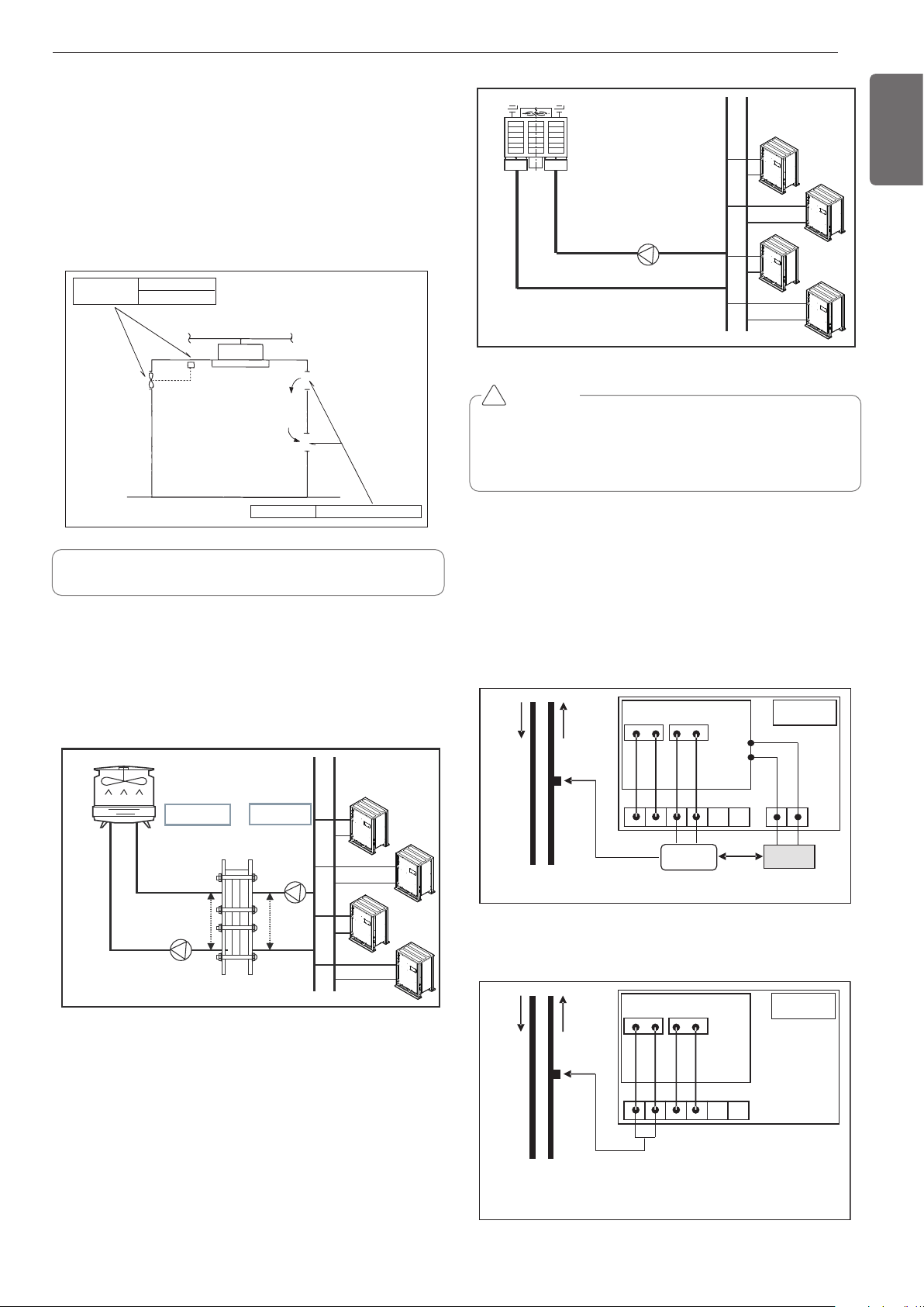
43
ENGLISH
In case the concentration exceeds the limit
When the concentration exceeds the limit, change original plan or take
one of the countermeasures shown below:
• Countermeasure 1
Provide opening for ventilation.
Provide 0.15% or more opening to floor space both above and below
door, or provide opening without door.
• Countermeasure 2
Provide gas leak alarm linked with mechanical ventilator.
Reducing the outside unit refrigerant qty.
[Open type cooling tower + Middle heat exchanger]
Heat exchanger is installed between the cooling tower and outside
unit system piping, and the temperature difference between 1st side
and 2nd side is maintained constantly.
Countermeasure 2
Gas leak alarm
Mechanical ventilator
Countermeasure 1
Opening effective to ventilation
Indoor unit
Pay a special attention to the place, such as a basement, etc.
where refrigerant can stay, since refrigerant is heavier than air.
Central Control(Use DDC Port)
Individual Control(Use 220V Output Port)
Water
In
※ BMS : Building Management System
Water
Out
Solenoid
Valve
CN_18
(220 V Out)
CN_22
(to DDC)
PI 485
DDC
BMS
1(L) 2(N) 3(L) 4(N)
Main PCB
Water
In
Water
Out
Solenoid
Valve
※ Refer to setting the function and turn on the power
When you individual control for water solenoid valve
control.
CN_18
(220 V Out)
CN_22
(to DDC)
1(L) 2(N) 3(L) 4(N)
Main PCB
Open type
cooling tower
1
st
side
2
nd
side
Heat exchange
Closed type
cooling tower
CAUTION
When the open type cooling tower is used and the water supply is
directly connected to the 2nd heat exchanger, product damage by
alien particle cannot be repaired for free.
- Always use the 2nd heat exchanger.
!
WATER SOLENOID VALVE CON-
TROL
COOLING TOWER APPLIED
METHOD

44
ENGLISH

US
1. Please call the installing contractor of your product, as warranty service will be pro-
vided by them.
2. If you have service issues that have not been addressed by the contractor, please
call 1-888-865-3026.
CANADA
Service call Number # : (888) LG Canada, (888) 542-2623