Loading ...
Loading ...
Loading ...
OPERATION
5
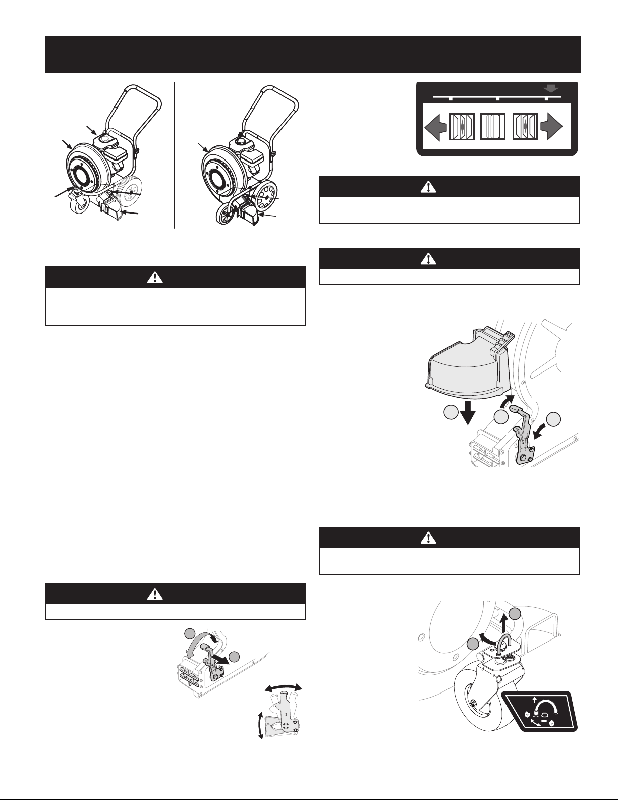
Controls
WARNING
Read and follow all safety rules and instructions in this manual before
attempting to operate this machine. Failure to comply with all safety rules
and instructions may result in personal injury.
Engine
Refer to the Engine Operator’s Manual for details regarding all engine-related
controls and features.
Discharge Chute
The discharge chute is located on the left side of the blower and directs the air flow.
Blower Direction Lever
Adjusts the louvers to change the direction of air flowing out of the discharge chute.
Caster Wheel Lock (If Equipped)
The front caster wheel can be locked in position for straight ahead travel or allowed
to swivel freely.
Operation
Starting & Stopping the Engine
Refer to the Engine Operator’s Manual for instructions on starting and stopping the
engine.
Adjusting the Blower Direction
The air flow can be directed to one of three directions using the Blower Direction
Lever to move the louvers.
WARNING
DO NOT stand in front of discharge area.
NOTE: The Blower Direction Lever must be
in the middle position when operating the
blower with the chute attachment to keep it
locked in place.
1. Pull the lever out and away
from the blower. See Figure 4.
2. Move the lever to the left to
direct airflow downward or
to the right to direct airflow
upward. See Figure 5.
3. Release lever
towards blower,
making sure it
secures into place.
WARNING
Exercise caution when operating blower. DO NOT allow the directional
discharge chute to point in the direction of bystanders or pets.
Attaching & Removing the Chute Attachment
WARNING
DO NOT operate without shields and guards in place.
To redirect airflow at a 90° angle during operation, a chute attachment is included
with your blower.
1. Pivot the blower
direction lever all the
way to the right, into
the highest position.
See 1 in Figure 6.
2. Slide the chute
attachment
downward, over the
opening. See 2 in
Figure 6.
3. Pivot the direction
lever to the middle
position to lock the
chute attachment in
place. See 3 in Figure 6.
4. To remove the chute attachment, first repeat step 1, then slide the chute
attachment upward and off the chute.
WARNING
Keep hands out of inlet and discharge openings while machine is running.
There are rotating blades inside.
Locking the Caster Wheel (If Equipped)
1. To lock the caster,
lift the lock pin, see
(a) in Figure 7, and
rotate it rearward,
releasing it into the
larger hole, see (b)
in Figure 7.
2. To unlock the
caster, lift the lock
pin and rotate it
forward, releasing
it into the smaller
hole.
Discharge
Chute
Blower
Housing
Blower
Direction
Lever
Discharge
Chute
Blower
Housing
Blower
Direction
Lever
Caster
Wheel
Lock
Engine
1150 Series
672 Series
Figure 3
2
Side view
Louvers
Blower Direction
Lever
1
Figure 4
BLOWER DIRECTION LEVER
UP
AIR FLOW
DO WN
Figure 5
2
1
3
Figure 6
a
b
Figure 7
Loading ...
Loading ...
Loading ...