Loading ...
Loading ...
Loading ...
INSTALLATION
08 GB
Figure 2
• RIGID PIPE CONNECTION
Connect directly to the manifold fittings.
• CONNECTION BY FLEXIBLE HOSE WITH MECHANICAL FITTINGS
We recommend this type of connection.
Screw the hose nuts directly onto the manifold fitting on the one hand and onto the stop cock of the piping on the other hand.
• CONNECTION BY SOFT RUBBER
We do not recommend this type of connection.
To be reserved solely for old installations not enabling any other option.
Screw the compliant end piece (2)
Fit the soft tube to the end piece on
the one hand and to the regulator or
to the valve outlet on the other hand.
(2) In all cases, make sure the seal is fitted. Following the connection operations, test the leak tightness using soapy water, testing by
flame is strictly prohibited.
Warning: If gas can be smelt in the vicinity of this appliance turn off the gas supply to the appliance and call the engineer directly. Do
not search for a leak with a naked flame.
WARNING:
Only professionally qualified person should undertake the task who will carry it out in accordance with the technical regulations in force
and following instructions.
To regulate the minimum flame the technician carry out the following instruction:
-Remove the knobs,
CASE 1: regulating screw visible inside the valve shaft (see figure 3A)
After lighting the burners, turn the control knob to the minimum setting and then remove the knob (this can easily be removed by applying
gentle pressure).
Using a small «Terminal» type screwdriver the regulating screw can be adjusted as in Figure 3A.
Turning the screw clockwise reduces the gas flow, whilst turning it anticlockwise increases the flow.
Use this adjustment to obtain a flame of approximately 3 to 4 mm in length and then replace the control knob.
When the gas supply available is LPG - the screw to set the idle flame must be turned (clockwise) to the end stop
Restore the knobs
CASE 2: regulating screw not visible (see figure 3B)
-Remove, grids, burners and lid.
-Remove the top plate
-Using a small screwdriver the regulating screw can be adjusted as in Figure 3C.
Turning the screw clockwise reduces the gas flow, whilst turning it anticlockwise increases the flow
-When the gas supply available is LPG the screw to set the idle flame must be turned (clockwise) to the end stop.
-When the gas supply available is NG gas the screw to set the idle flame must be turned anticlockwise of 1/2 turn from complete close
position. (flame of approximately 3 to 4 mm in length)
-Restore the top plate, making sure to correctly reassemble each disassembled or disconnected piece and pay attention to not damage
parts, (in case the technician must replace it with original spare parts.
-Restore burners, grids lid and knobs.
The calorific capacity and pressure of the gas vary according to the type of gas.
When changing the gas, the technician should successively :
1-Disconnect the appliance from power supply
2-Make the "GAS CONNECTION" to the installation as described above,
3-Close the gas valve before the appliance
4-CHANGE THE JETS
5-REGULATING THE MINIMUN FLAME
To adapt the Hob for use with different types of gas, carry out the following instructions:
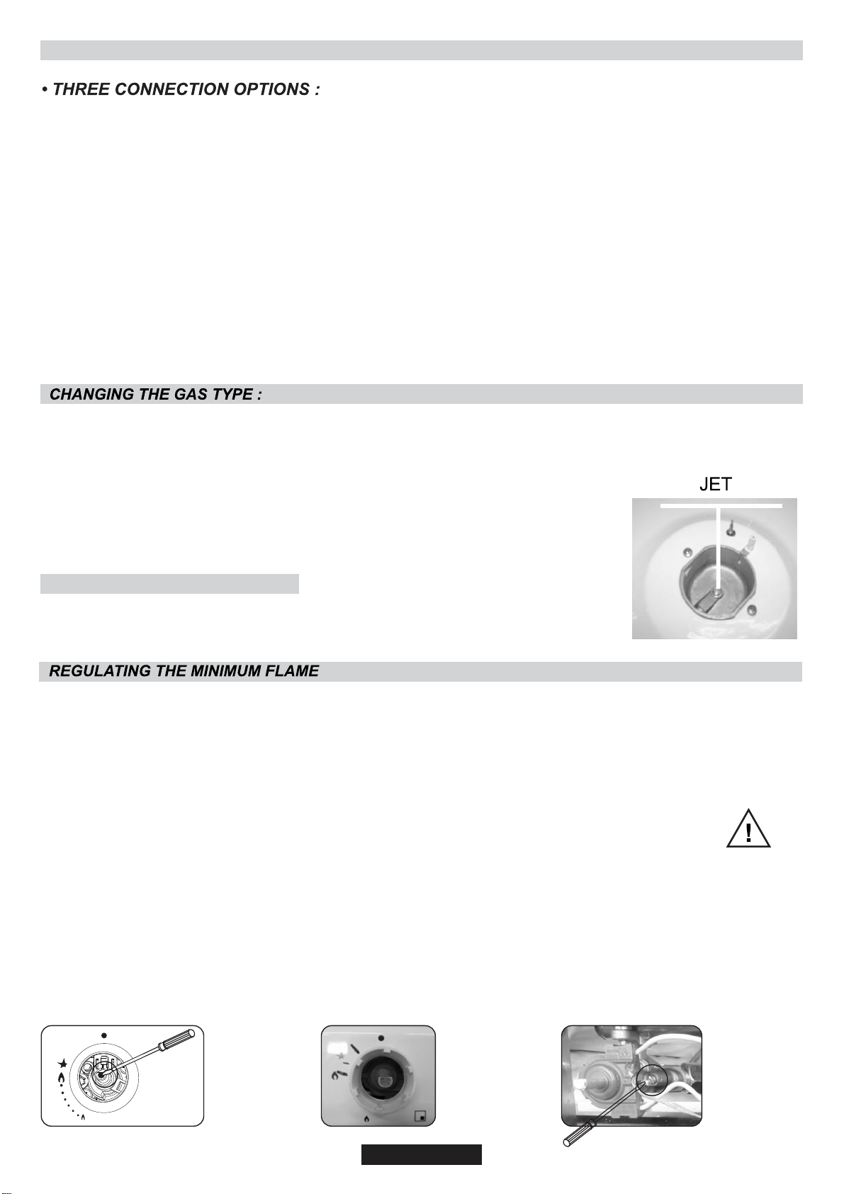
• Remove the grids and burners
• Insert on hexagonal spanner (7 mm) into the burner support (Figure 2)
• Unscrew the injector and replace it with one suitable for the gasto be used (see gas type table)
CHANGE THE JETS :
Warning :
Never loosen
the others
screws !
Figure 3A Figure 3B Figure 3C
Loading ...
Loading ...
Loading ...