
www.lg.com
IPS LED MONITOR
LED MONITOR
*
Owner's Manual
Please read the safety information carefully
before using the product.
34UM94
34UM95
34UM95C
* LG LED Monitors are LCD Monitors with LED Backlighting.

ENGLISH
2
TABLE OF CONTENTS
TABLE OF CONTENTS
3 LICENSE
4 ASSEMBLING AND
PREPARING
4 Product Composition
5 Product and Button Description
5 - How to Use the Joystick Button
6 - Input Connector
8 Moving and Lifting the Monitor
9 Installing the Monitor
9 - Assembling the Stand
10 - Detaching the Stand
11 - Installing on a Table
12 - Adjusting the angle
12 - Tidying up Cables
13 - Installing the Wall Mount Plate
13 - Installing on the Wall
15 - Using the Kensington Lock
16 USING THE MONITOR
16 Connecting to a PC
16 - HDMI Connection
17 - DisplayPort Connection
17 - Thunderbolt ( ) Connection
18 Connecting AV Devices
18 - HDMI Connection
18 Connecting Peripherals
18 - USB Cable connection - PC
19 - Connecting Headphones
20 USER SETTINGS
20 Activating the Main Menu
20 - Main Menu Features
21 User Settings
21 - Menu Settings
22 - Ratio
23 - Function
24 - PBP
26 - Picture
27 - Color
28 - Settings
29 - Reset
30 - Reader
31 TROUBLESHOOTING
33 PRODUCT SPECIFICATION
35 Factory Support Mode
35 HDMI Timing (Video)
35 Power LED
36 PROPER POSTURE
36 Proper Posture for Using the Monitor
WARNING: This product contains chemicals known to the State of California to cause cancer and birth
defects or other reproductive harm. Wash hands after handling.

ENGLISH
3
LICENSE
LICENSE
Each model has different licenses. Visit www.lg.com for more information on the license.
The terms HDMI and HDMI High-Definition Multimedia Interface, and the HDMI
logo are trademarks or registered trademarks of HDMI Licensing LLC in the
United States and other countries.
VESA, VESA logo, DisplayPort compliance logo and DisplayPort compliance
logo for dual-mode source devices are all registered trademarks of the Video
Electronics Standards Association.
ENGLISH
4
ASSEMBLING AND PREPARING
ASSEMBLING AND PREPARING
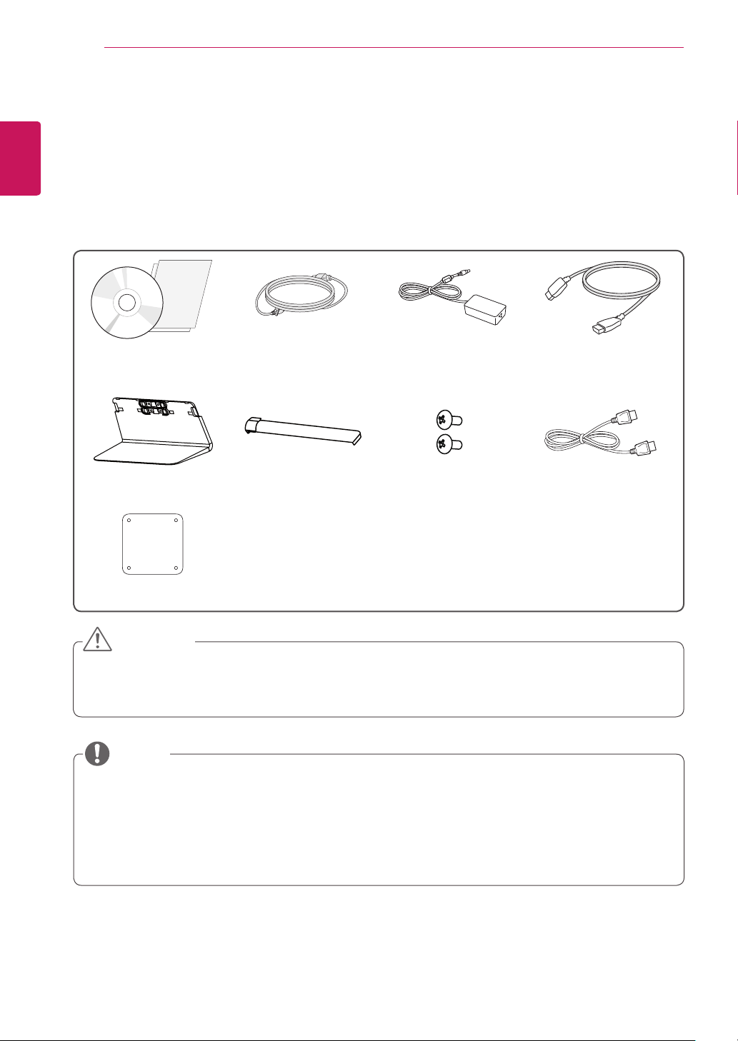
Product Composition
Please check whether all the components are included in the box before using the product. If there are
any missing components, contact the retailer where you purchased the product. Note that the product and
related components may look different from those shown here.
CD(Owner's Manual /
Software / Guides) /
Cards
Power cord AC/DC Adapter HDMI cable
Stand Base Screw Cover
2 Screws
(M4 x L10)
DisplayPort Cable
(Depending on country)
Clear sheet
y
Always use genuine LG components to ensure safety and product performance.
y
The product warranty will not cover damage or injury caused by the use of unauthorized components.
y
It is recommend that use the supplied components.
CAUTION
y
The components may look different from those illustrated here.
y
Without prior notice, all product information and specifications contained in this manual are subject to
change to improve the performance of the product.
y
To purchase optional accessories, visit an electronics store or an online shopping site, or contact the
retailer from which you purchased the product.
y
The power cord provided may differ depending upon the region.
NOTE

ENGLISH
5
ASSEMBLING AND PREPARING
Product and Button Description
Joystick
Button
Power indicator
y
On Power on
y
Off Power off
How to Use the Joystick Button
You can easily control the functions of the monitor by pressing the joystick button or moving it left/right with
your finger.
Basic Functions
Power on
Press the joystick button once with your finger to turn on the
monitor.
Power off
Press and hold the joystick button once with your finger to turn off
the monitor.
◄/►
Volume
Control
You can control the volume by moving the joystick button left/right.
y
The joystick button is located at the bottom of the monitor.
y
Before turning on the monitor, please make sure that the DC switch on the rear side of product is On.
(Only 34UM95-PE, 34UM94-PE, 34UM95C-PD)
NOTE
ENGLISH
6
ASSEMBLING AND PREPARING
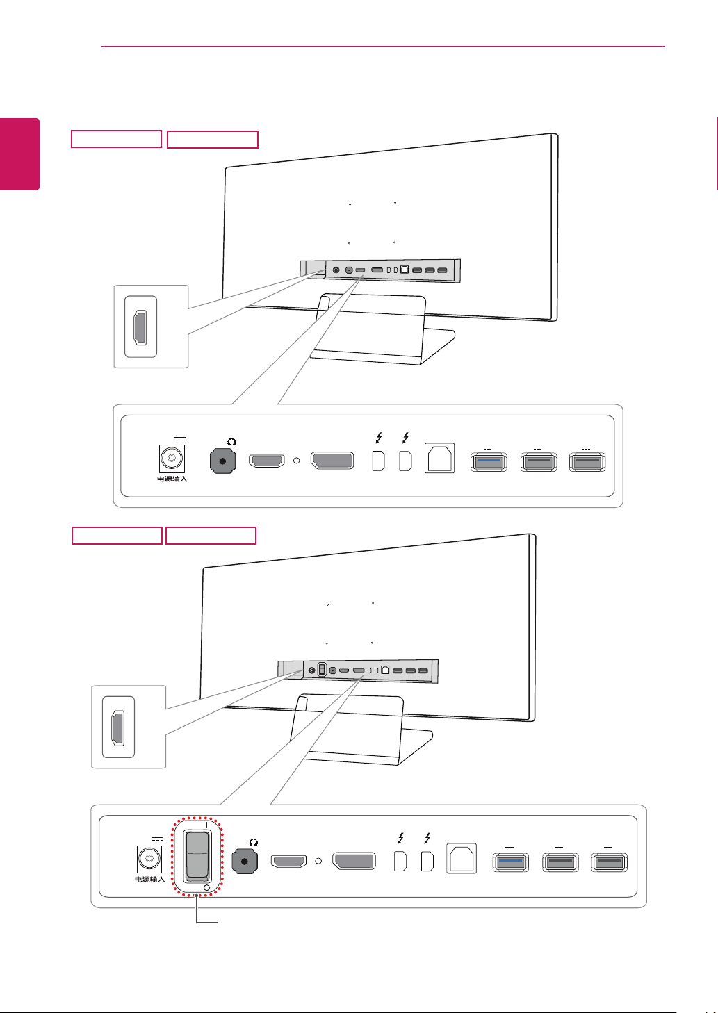
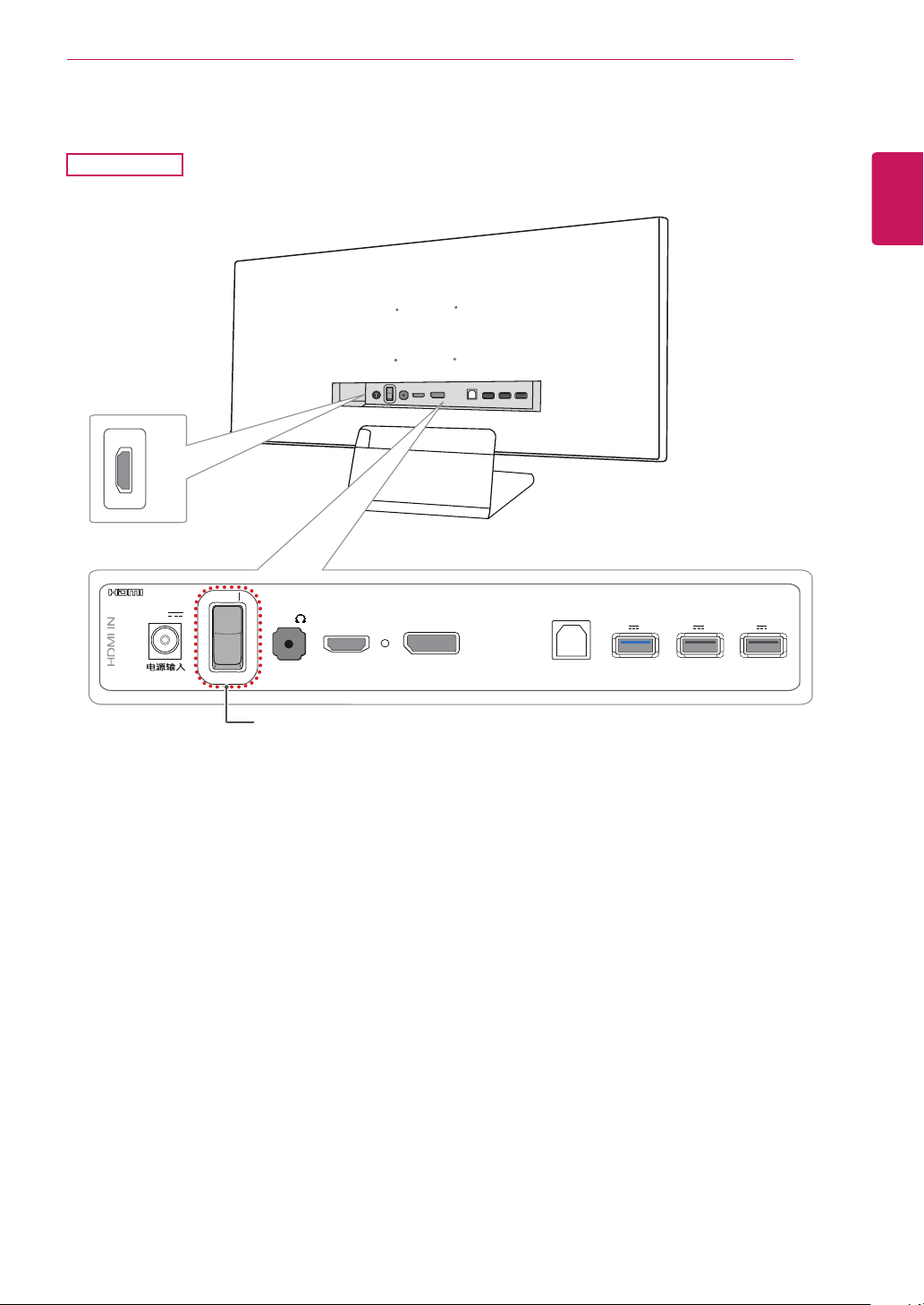
Input Connector
34UM95-PE
34UM95-PD
DC-IN
(19 V )
DP-IN
HDMI IN 1
H/P
USB UP
USB IN 1
5 V 1.1 A
USB IN 2
5 V 0.5 A
USB IN 3
5 V 0.5 A
HDMI
IN
2
HDMI IN 2
HDMI IN 2
HDMI
IN
2
DC-IN
(19 V )
DP-IN
HDMI IN 1
H/P
USB UP
USB IN 1
5 V 1.1 A
USB IN 2
5 V 0.5 A
USB IN 3
5 V 0.5 A
ON
OFF
DC Switch
34UM94-PD
34UM94-PE
ENGLISH
7
ASSEMBLING AND PREPARING
DC-IN
(19 V )
DP IN
HDMI IN 1
H/P
USB UP
USB IN 1
5 V 1.1 A
USB IN 2
5 V 0.5 A
USB IN 3
5 V 0.5 A
HDMIIN
2
HDMI IN 2
HDMI IN 2
HDMI
IN
2
DC-IN
(19 V )
DP IN
HDMI IN 1
H/P
USB UP
USB IN 1
5 V 1.1 A
USB IN 2
5 V 0.5 A
USB IN 3
5 V 0.5 A
ON
OFF
HDMI IN 2
2
DC-IN
(19 V )
DP-IN
HDMI IN 1
H/P
USB UP
USB IN 1
5 V 1.1 A
USB IN 2
5 V 0.5 A
USB IN 3
5 V 0.5 A
ON
DC Switch
34UM95C-PD
ENGLISH
8
ASSEMBLING AND PREPARING
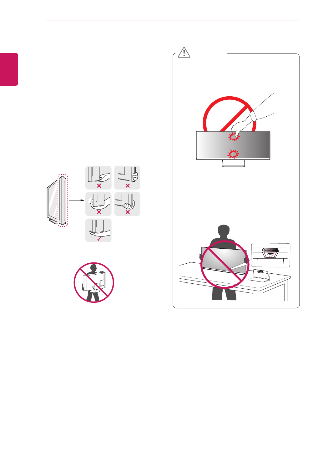
Moving and Lifting the
Monitor
When moving or lifting the monitor, follow these
instructions to prevent the monitor from being
scratched or damaged and to ensure safe trans-
portation, regardless of its shape or size.
y
It is advisable to place the monitor in the origi-
nal box or packing material before attempting
to move it.
y
Before moving or lifting the monitor, discon-
nect the power cord and all other cables.
y
Hold the bottom and side of the monitor frame
firmly. Do not hold the panel itself.
y
When holding the monitor, the screen should
face toward you to prevent it from being
scratched.
y
When transporting the monitor, do not expose
the monitor to shock or excessive vibration.
y
When moving the monitor, keep it upright and
never turn the monitor on its side or tilt it side-
ways.
y
Avoid touching the monitor screen as much as
possible.
- This may result in damage to the screen or
some of the pixels used to create images.
y
If you use the monitor panel without the stand
base, its joystick button may cause the moni-
tor to become unstable and fall, resulting in
damage to the monitor or human injury. In
addition, this may cause the joystick button to
malfunction.
CAUTION

ENGLISH
9
ASSEMBLING AND PREPARING
Installing the Monitor
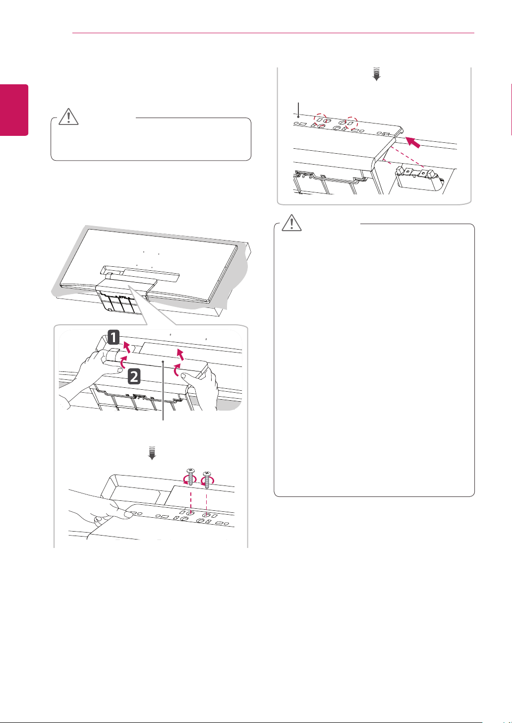
Assembling the Stand
1
Place the screen face down.
Stand Hinge
y
To protect the screen from scratches, cover
the surface with a soft cloth.
CAUTION
2
Mount the stand base onto the stand hinge
as shown in the illustration. Fix two screws
into the back of the stand base and close the
screw cover.
Stand Base
120 mm
(4.7 inch)
Screw Cover
or
100 mm
(3.9 inch)
y
The stand height is adjustable by 20 mm
(0.7 inch).
y
When tightening the screws after mounting
the stand base onto the stand hinge, be sure
to hold the stand base with your hand. Other-
wise, the product may fall, causing personal
injury or damage to the product.
y
Be careful not to hurt your hand on the edges
of the screw covers.
y
Applying excessive force when tightening
screws may cause damage to the monitor.
Damage caused in this way will not be cov-
ered by the product warranty.
y
If you use the monitor panel without the
stand base, its joystick button may cause the
monitor to become unstable and fall, result-
ing in damage to the monitor or human injury.
In addition, this may cause the joystick button
to malfunction.
CAUTION
ENGLISH
10
ASSEMBLING AND PREPARING
Detaching the Stand
1
Place the screen face down.
y
To protect the screen from scratches, cover
the surface with a soft cloth.
CAUTION
2
Detach the screw cover from the stand base
as shown in the illustration and then remove
the two screws on the back to detach the
stand base from the hinge.
Screw Cover
Stand Base
y
Illustrations in this document represent typical
procedures, so they may look different from
the actual product.
y
Do not carry the monitor upside down by just
holding the base. This may cause the monitor
to fall off the stand and could result in personal
injury.
y
When lifting or moving the monitor, do not
touch the monitor screen. The force applied to
the monitor screen may cause damage to it.
y
If you use the monitor panel without the stand
base, its joystick button may cause the moni-
tor to become unstable and fall, resulting in
damage to the monitor or human injury. In
addition, this may cause the joystick button to
malfunction.
y
When removing the screws to detach the
stand base from the hinge, be sure to hold
the stand base with your hand. Otherwise, the
product may fall, causing personal injury or
damage to the product.
CAUTION
ENGLISH
11
ASSEMBLING AND PREPARING
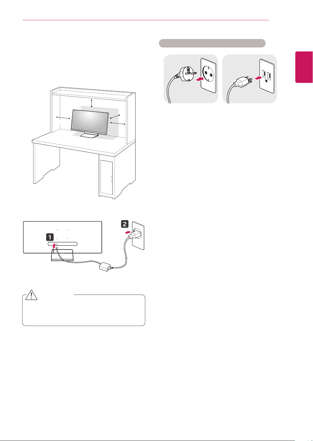
Installing on a Table
1
Lift the monitor and place it on the table in an
upright position. Place the monitor at least
10 cm away from the wall to ensure sufficient
ventilation.
10 cm
10 cm (3.9 inch)
10 cm
10 cm
2
Connect the power adapter to the monitor and
then plug the power cord into the wall outlet.
3
Press the joystick button on the bottom of the
monitor to turn on the monitor.
y
Unplug the power cord before moving or
installing the monitor. There is risk of electric
shock.
CAUTION
Cautions When Connecting Power Cord
100-240 V ~
y
Make sure to use the power cord that is pro-
vided in the product package and connect it to
a grounded power outlet.
y
If you need another power cord, please con-
tact your local dealer or the nearest retail
store.
ENGLISH
12
ASSEMBLING AND PREPARING
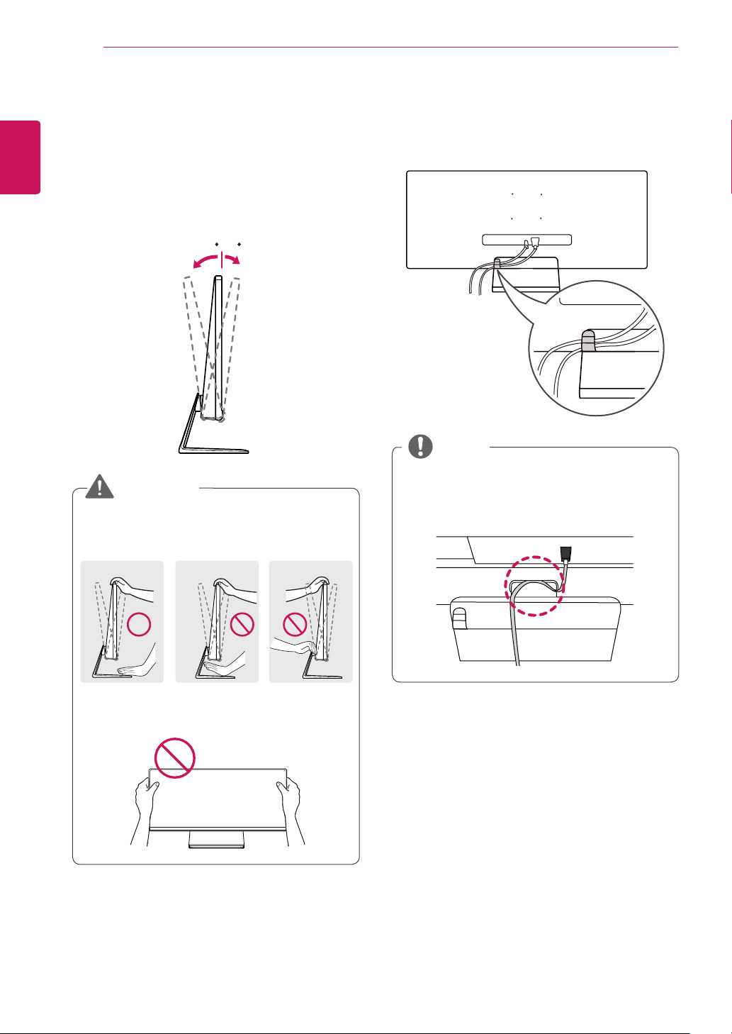
Adjusting the angle
1
Place the monitor mounted on the stand base
in an upright position.
2
Adjust the angle of the screen. The angle of
the screen can be adjusted forward or back-
ward from -5° to 15° for a comfortable
viewing experience.
-515
Front
Rear
y
When you adjust the angle, do not hold the
stand as shown on the following illustration.
You may injure your fingers.
-515
y
Be careful not to touch or press the screen
area when adjusting the angle of the monitor.
-515
WARNING
Tidying up Cables
Tidy up cables using the cable holder on the stand
base as shown in the illustration.
y
Cables can get caught in the hinge area as
shown in the illustration, so be careful when
organizing cables.
NOTE
ENGLISH
13
ASSEMBLING AND PREPARING
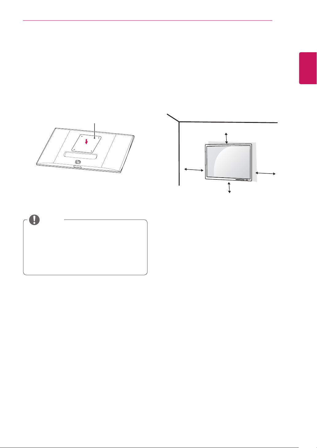
Installing on the Wall
Install the monitor at least 10 cm (3.9 inch) away
from the wall and leave about 10 cm (3.9 inch)
of space at each side of the monitor to ensure
sufficient ventilation. Detailed installation instruc-
tions can be obtained from your local retail store.
Alternatively, please refer to the manual for how to
install and set up a tilting wall mounting bracket.
10 cm (3.9 inch)
10 cm
10 cm
10 cm
To install the monitor to a wall, attach a wall mount-
ing bracket (optional) to the back of the monitor.
Make sure that the wall mounting bracket is se-
curely fixed to the monitor and to the wall.
1
If you use screws longer than the standard
length, it may damage the inside of the prod-
uct.
2
A non-VESA standard screw may damage the
product and cause the monitor to fall. LG Elec-
tronics is not liable for any accidents relating
to the use of non-standard screws.
Installing the Wall Mount Plate
This monitor meets the specifications for the wall
mount plate or other compatible devices.
1
Place the screen face down. To protect the
screen from scratches, cover the surface with
a soft cloth.
2
Attach the clear sheet to the back of the moni-
tor and align it with the screw holes.
Clear sheet
(PET sheet)
3
Place the wall mount plate onto the monitor
and align it with the screw holes.
4
Tighten the four screws to fix the plate to the
monitor using a screwdriver.
y
The wall mount plate is sold separately.
y
For more information on installation, refer to
the wall mount plate's installation guide.
y
Be careful not to apply too much force while
mounting the wall mount plate as it may cause
damage to the screen
NOTE

ENGLISH
14
ASSEMBLING AND PREPARING
Wall Mount (A x B) 100 x 100
Stand Screw M4 x L10
Required Screws 4
Wall Mount Plate
(Optional)
RW120
y
Wall Mount (A x B)
A
B
y
Unplug the power cord before moving or install-
ing the monitor to avoid electric shock.
y
Installing the monitor on the ceiling or on a
slanted wall may result in the monitor falling off,
which could lead to injury. Use an authorized LG
wall mount and contact the local dealer or quali-
fied personnel.
y
Applying excessive force when tightening
screws may cause damage to the monitor. Dam-
age caused in this way will not be covered by
the product warranty.
y
Use the wall mounting bracket and screws that
conform to VESA standards. Damage caused by
the use or misuse of inappropriate components
will not be covered by the product warranty.
y
When measured from the back of the monitor,
the length of each installed screw must be 8 mm
(0.3 inch) or less.
Wall Mount Plate
Back of the Monitor
Screw
Dimensions
: M4 x L10
Wall Mount Plate
Back of the Monitor
Max 8 mm (0.3 inch)
CAUTION
y
Use the screws specified by VESA standards.
y
The wall mount kit includes the installation guide
and all necessary parts.
y
The wall mounting bracket is optional. You can
obtain optional accessories from your local dealer.
y
The length of the screw may differ for each wall
mounting bracket. Be sure to use the proper
length.
y
For more information, please refer to the user
manual for the wall mounting bracket.
NOTE
ENGLISH
15
ASSEMBLING AND PREPARING
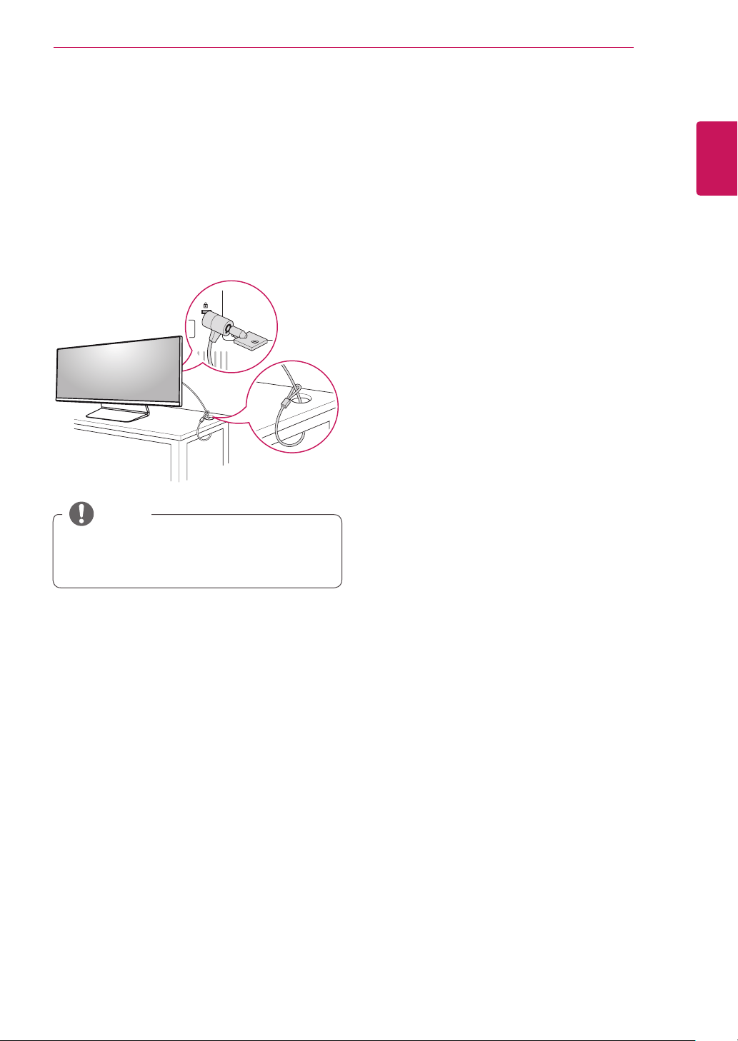
Using the Kensington Lock
The connector for the Kensington security system
is located at the back of the monitor.
For more information on installation and usage,
refer to the Kensington lock owner's manual or visit
the website at http://www.kensington.com.
Connect the monitor to a table using the Kensing-
ton security system cable.
y
The Kensington security system is optional.
You can obtain optional accessories from most
electronics stores.
NOTE
ENGLISH
16
USING THE MONITOR
USING THE MONITOR
y
The following instructions are based on the
34UM95-PD model. Illustrations in this manual
may differ from the actual product.
Press the joystick button, go to Menu → Easy con-
trol → Input, and then select the input option.
y
Do not press the screen for a prolonged time.
This may cause image distortion.
y
Do not display a still image on the screen
for a prolonged time. This may cause image
retention. Use a screensaver if possible.
CAUTION
y
When connecting the power cord to the out-
let, use a grounded (3-hole) power strip or a
grounded power outlet.
y
The monitor may flicker when turned on in
an area where the temperature is low. This is
normal.
y
Sometimes red, green or blue spots may ap-
pear on the screen. This is normal.
NOTE
Connecting to a PC
y
This monitor supports the *Plug and Play fea-
ture.
* Plug and Play: A feature that allows you to add a
device to your computer without having to recon-
figure anything or install any manual drivers.
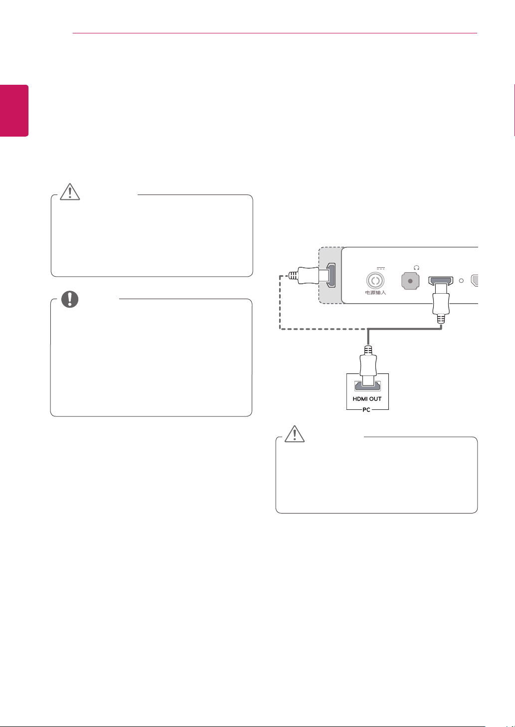
HDMI Connection
Transmits digital video and audio signals from your
PC to the monitor. Connect your PC to the monitor
using the HDMI cable as shown in the illustration
below.
D
C
-I
N
(19 V )
DP-IN
HDMI IN
1
H
/
P
USB UP
USB IN 1
5 V 1.1 A
USB IN 2
5 V 0.5 A
USB IN 3
5 V 0.5 A
HDMI IN
2
D
C
-I
N
(19 V )
DP
-
IN
HDMI IN
1
H/P
US
B
U
P
HDMIIN
2
US
B IN 1
5 V 1.1 A
US
B IN
2
5 V 0.5 A
US
B IN
3
5 V 0.5 A
D
C-I
N
(19 V )
DP-IN
HDMI
IN
1
H
/
P
US
B
U
P
HDMI IN
2
US
B IN 1
5 V 1.1 A
US
B IN
2
5 V 0.5 A
US
B IN
3
5 V 0.5 A
D
C
-I
N
(19 V )
DP
-
IN
HDMI IN 1
H
/
P
US
B UP
HDMI IN 2
US
B IN 1
5 V 1.1 A
US
B IN
2
5 V 0.5 A
US
B IN
3
5 V 0.5 A
DC
-I
N
(19 V )
DP
-
IN
HDMI
IN 1
US
B
U
P
HDMIIN
2
US
B IN 1
5 V 1.1 A
US
B IN
2
5 V 0.5 A
US
B IN
3
5 V 0.5 A
DP OUT
5
V
0
.
9
A
A
UDI
O
IN
(
P
C)
5 V 0.5 A
H/P
US
B IN 1
US
B IN 2
USB IN
3
U
SB UP
DVI
-
DIN
DP IN
5 V 0.9 A
HDMI 1/
MHL
HDMI
2
DC
-I
N
(19 V )
DP-IN
HDMI IN 1
H/P
US
B
U
P
HDMI IN 2
US
B IN 1
5 V 1.1 A
US
B IN
2
5 V 0.5 A
US
B IN 3
5 V 0.5 A
DC
-I
N
(19 V )
DP
-
IN
HDMI
IN 1
US
B UP
H
DMI IN
2
USB IN 1
5 V 1.1 A
USB IN 2
5 V 0.5 A
USB IN 3
5 V 0.5 A
y
Connecting your PC to the monitor using the
HDMI cable may cause device compatibility
issues.
y
Using a DVI to HDMI / DP(DisplayPort) to
HDMI cable may cause compatibility issues.
CAUTION
ENGLISH
17
USING THE MONITOR
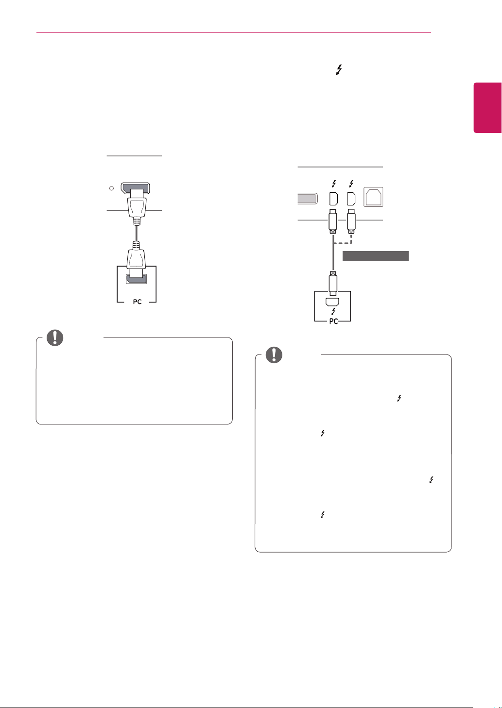
DisplayPort Connection
Transmits digital video and audio signals from your
PC to the monitor. Connect the monitor to your PC
using the display port cable as shown in the illus-
tration below:
D
C
-I
N
(19 V )
DP-IN
HDMI IN
1
H
/
P
USB UP
USB IN 1
5 V 1.1 A
USB IN 2
5 V 0.5 A
USB IN 3
5 V 0.5 A
HDMI IN
2
D
C
-I
N
(19 V )
DP
-
IN
HDMI IN
1
H/P
US
B
U
P
HDMIIN
2
US
B IN 1
5 V 1.1 A
US
B IN
2
5 V 0.5 A
US
B IN
3
5 V 0.5 A
D
C-I
N
(19 V )
DP-IN
HDMI
IN
1
H
/
P
US
B
U
P
HDMI IN
2
US
B IN 1
5 V 1.1 A
US
B IN
2
5 V 0.5 A
US
B IN
3
5 V 0.5 A
D
C
-I
N
(19 V )
DP
-
IN
HDMI IN 1
H
/
P
US
B UP
HDMI IN 2
US
B IN 1
5 V 1.1 A
US
B IN
2
5 V 0.5 A
US
B IN
3
5 V 0.5 A
DC
-I
N
(19 V )
DP
-
IN
HDMI
IN 1
US
B
U
P
HDMIIN
2
US
B IN 1
5 V 1.1 A
US
B IN
2
5 V 0.5 A
US
B IN
3
5 V 0.5 A
DP OUT
5
V
0
.
9
A
A
UDI
O
IN
(
P
C)
5 V 0.5 A
H/P
US
B IN 1
US
B IN 2
USB IN
3
U
SB UP
DVI
-
DIN
DP IN
5 V 0.9 A
HDMI 1/
MHL
HDMI
2
DC
-I
N
(19 V )
DP-IN
HDMI IN 1
H/P
US
B
U
P
HDMI IN 2
US
B IN 1
5 V 1.1 A
US
B IN
2
5 V 0.5 A
US
B IN 3
5 V 0.5 A
DC
-I
N
(19 V )
DP
-
IN
HDMI
IN 1
US
B UP
H
DMI IN
2
USB IN 1
5 V 1.1 A
USB IN 2
5 V 0.5 A
USB IN 3
5 V 0.5 A
NOTE
y
There may be no video or audio output de-
pending on the DP (DisplayPort) version of the
PC.
y
For using Mini DP to DP (Mini DisplayPort to
DisplayPort) cable, it is recommended that you
use DisplayPort 1.2 cable.
Thunderbolt ( ) Connection
(34UM95 / 34UM94 Model only)
You can connect your high-resolution display or
high-performance data device to the monitor via a
Thunderbolt port. Connect your external device to
the monitor using the Thunderbolt cable as illus-
trated below.
D
C
-I
N
(19 V )
DP-IN
HDMI IN
1
H
/
P
USB UP
USB IN 1
5 V 1.1 A
USB IN 2
5 V 0.5 A
USB IN 3
5 V 0.5 A
HDMI IN
2
D
C
-I
N
(19 V )
DP
-
IN
HDMI IN
1
H/P
US
B
U
P
HDMIIN
2
US
B IN 1
5 V 1.1 A
US
B IN
2
5 V 0.5 A
US
B IN
3
5 V 0.5 A
D
C-I
N
(19 V )
DP-IN
HDMI
IN
1
H
/
P
US
B
U
P
HDMI IN
2
US
B IN 1
5 V 1.1 A
US
B IN
2
5 V 0.5 A
US
B IN
3
5 V 0.5 A
D
C
-I
N
(19 V )
DP
-
IN
HDMI IN 1
H
/
P
US
B UP
HDMI IN 2
US
B IN 1
5 V 1.1 A
US
B IN
2
5 V 0.5 A
US
B IN
3
5 V 0.5 A
DC
-I
N
(19 V )
DP
-
IN
HDMI
IN 1
US
B
U
P
HDMIIN
2
US
B IN 1
5 V 1.1 A
US
B IN
2
5 V 0.5 A
US
B IN
3
5 V 0.5 A
DP OUT
5
V
0
.
9
A
A
UDI
O
IN
(
P
C)
5 V 0.5 A
H/P
US
B IN 1
US
B IN 2
USB IN
3
U
SB UP
DVI
-
DIN
DP IN
5 V 0.9 A
HDMI 1/
MHL
HDMI
2
DC
-I
N
(19 V )
DP-IN
HDMI IN 1
H/P
US
B
U
P
HDMI IN 2
US
B IN 1
5 V 1.1 A
US
B IN
2
5 V 0.5 A
US
B IN 3
5 V 0.5 A
DC
-I
N
(19 V )
DP
-
IN
HDMI
IN 1
US
B UP
H
DMI IN
2
USB IN 1
5 V 1.1 A
USB IN 2
5 V 0.5 A
USB IN 3
5 V 0.5 A
(sold separately)
y
The maximum data transmission rate of each
port is 20 Gb/s.
y
Make sure to use a Thunderbolt (
) certified
cable. Otherwise, this may cause the device to
malfunction.
y
Thunderbolt (
) is supported in such environ-
ments as Windows 7, Windows 8.1 and New
Mac Pro (Over Mac OS 10.9.1).
y
The ASM driver on the Owner's Manual CD
must be installed to use the Thunderbolt (
)
port.
y
The ability to set up dual monitors using the
Thunderbolt (
) and daisy-chaining technology
depends on the performance of your video
card.
NOTE
ENGLISH
18
USING THE MONITOR
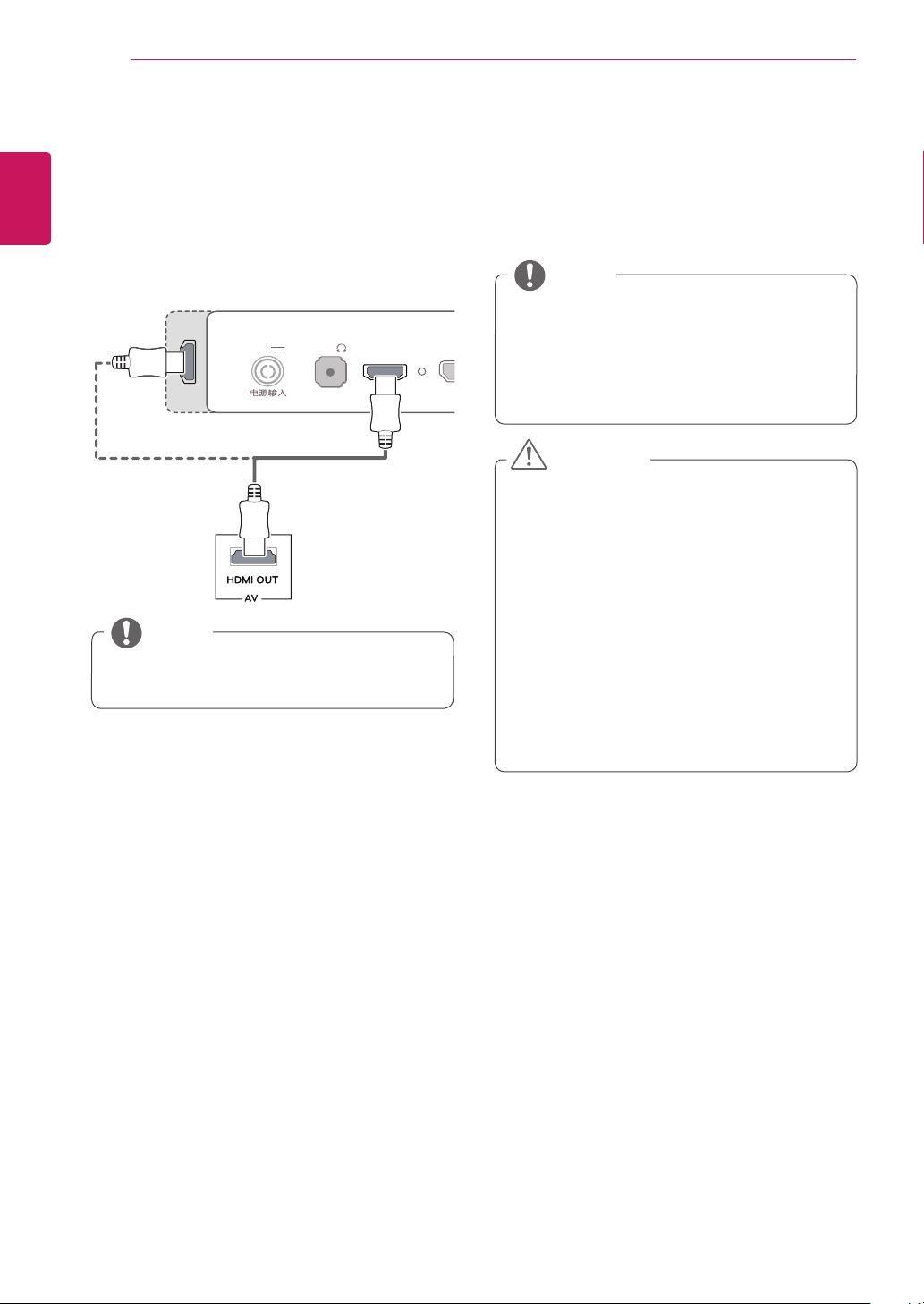
Connecting AV Devices
HDMI Connection
HDMI transmits digital video and audio signals
from your AV device to the monitor. Connect your
AV device to the monitor using the HDMI cable as
shown in the illustration below.
D
C
-I
N
(19 V )
DP-IN
HDMI IN
1
H
/
P
USB UP
USB IN 1
5 V 1.1 A
USB IN 2
5 V 0.5 A
USB IN 3
5 V 0.5 A
HDMI IN
2
D
C
-I
N
(19 V )
DP
-
IN
HDMI IN
1
H/P
US
B
U
P
HDMIIN
2
US
B IN 1
5 V 1.1 A
US
B IN
2
5 V 0.5 A
US
B IN
3
5 V 0.5 A
D
C-I
N
(19 V )
DP-IN
HDMI
IN
1
H
/
P
US
B
U
P
HDMI IN
2
US
B IN 1
5 V 1.1 A
US
B IN
2
5 V 0.5 A
US
B IN
3
5 V 0.5 A
D
C
-I
N
(19 V )
DP
-
IN
HDMI IN 1
H
/
P
US
B UP
HDMI IN 2
US
B IN 1
5 V 1.1 A
US
B IN
2
5 V 0.5 A
US
B IN
3
5 V 0.5 A
DC
-I
N
(19 V )
DP
-
IN
HDMI
IN 1
US
B
U
P
HDMIIN
2
US
B IN 1
5 V 1.1 A
US
B IN
2
5 V 0.5 A
US
B IN
3
5 V 0.5 A
DP OUT
5
V
0
.
9
A
A
UDI
O
IN
(
P
C)
5 V 0.5 A
H/P
US
B IN 1
US
B IN 2
USB IN
3
U
SB UP
DVI
-
DIN
DP IN
5 V 0.9 A
HDMI 1/
MHL
HDMI
2
DC
-I
N
(19 V )
DP-IN
HDMI IN 1
H/P
US
B
U
P
HDMI IN 2
US
B IN 1
5 V 1.1 A
US
B IN
2
5 V 0.5 A
US
B IN 3
5 V 0.5 A
DC
-I
N
(19 V )
DP
-
IN
HDMI
IN 1
US
B UP
H
DMI IN
2
USB IN 1
5 V 1.1 A
USB IN 2
5 V 0.5 A
USB IN 3
5 V 0.5 A
y
Using a DVI to HDMI / DP(DisplayPort) to
HDMI cable may cause compatibility issues.
NOTE
Connecting Peripherals
USB Cable connection - PC
The USB port on the product functions as a USB
hub.
y
Make sure to install the most recent Windows
OS service pack before using the product.
y
Peripheral devices are sold separately.
y
A keyboard, mouse, or USB device can be
connected to the USB port.
NOTE
Cautions When Using a USB Device
y
A USB device with an automatic recognition
program installed, or that uses its own driver,
may not be recognized.
y
Some USB devices may not be supported or
may not work properly.
y
It is recommended to use a USB hub or hard
disk drive with power supplied. (If the power
supply is not adequate, the USB device may
not be recognized properly.)
y
Since USB IN 2 and 3 only support USB 2.0,
it may not work when USB 3.0 devices are
connected.
CAUTION

ENGLISH
19
USING THE MONITOR
HDMI/DP (DisplayPort) connection
To use USB 3.0, connect the A-B type USB 3.0
cable of the product to the PC.
Peripheral devices connected to the USB IN port
can be controlled from the PC.
D
C
-I
N
(19 V )
DP-IN
HDMI IN
1
H
/
P
USB UP
USB IN 1
5 V 1.1 A
USB IN 2
5 V 0.5 A
USB IN 3
5 V 0.5 A
HDMI IN
2
D
C
-I
N
(19 V )
DP
-
IN
HDMI IN
1
H/P
US
B
U
P
HDMIIN
2
US
B IN 1
5 V 1.1 A
US
B IN
2
5 V 0.5 A
US
B IN
3
5 V 0.5 A
D
C-I
N
(19 V )
DP-IN
HDMI
IN
1
H
/
P
US
B
U
P
HDMI IN
2
US
B IN 1
5 V 1.1 A
US
B IN
2
5 V 0.5 A
US
B IN
3
5 V 0.5 A
D
C
-I
N
(19 V )
DP
-
IN
HDMI IN 1
H
/
P
US
B UP
HDMI IN 2
US
B IN 1
5 V 1.1 A
US
B IN
2
5 V 0.5 A
US
B IN
3
5 V 0.5 A
DC
-I
N
(19 V )
DP
-
IN
HDMI
IN 1
US
B
U
P
HDMIIN
2
US
B IN 1
5 V 1.1 A
US
B IN
2
5 V 0.5 A
US
B IN
3
5 V 0.5 A
DP OUT
5
V
0
.
9
A
A
UDI
O
IN
(
P
C)
5 V 0.5 A
H/P
US
B IN 1
US
B IN 2
USB IN
3
U
SB UP
DVI
-
DIN
DP IN
5 V 0.9 A
HDMI 1/
MHL
HDMI
2
DC
-I
N
(19 V )
DP-IN
HDMI IN 1
H/P
US
B
U
P
HDMI IN 2
US
B IN 1
5 V 1.1 A
US
B IN
2
5 V 0.5 A
US
B IN 3
5 V 0.5 A
DC
-I
N
(19 V )
DP
-
IN
HDMI
IN 1
US
B UP
H
DMI IN
2
USB IN 1
5 V 1.1 A
USB IN 2
5 V 0.5 A
USB IN 3
5 V 0.5 A
(sold separately)
(sold separately)
Thunderbolt ( ) connection
(34UM95 / 34UM94 Model only)
Peripheral devices connected to the USB IN port
can be controlled from the PC.
If you change the input on the menu while a device
is in connection via the Thunderbolt port, then the
device in connection via the USB port may not
work properly.
D
C
-I
N
(19 V )
DP-IN
HDMI IN
1
H
/
P
USB UP
USB IN 1
5 V 1.1 A
USB IN 2
5 V 0.5 A
USB IN 3
5 V 0.5 A
HDMI IN
2
D
C
-I
N
(19 V )
DP
-
IN
HDMI IN
1
H/P
US
B
U
P
HDMIIN
2
US
B IN 1
5 V 1.1 A
US
B IN
2
5 V 0.5 A
US
B IN
3
5 V 0.5 A
D
C-I
N
(19 V )
DP-IN
HDMI
IN
1
H
/
P
US
B
U
P
HDMI IN
2
US
B IN 1
5 V 1.1 A
US
B IN
2
5 V 0.5 A
US
B IN
3
5 V 0.5 A
D
C
-I
N
(19 V )
DP
-
IN
HDMI IN 1
H
/
P
US
B UP
HDMI IN 2
US
B IN 1
5 V 1.1 A
US
B IN
2
5 V 0.5 A
US
B IN
3
5 V 0.5 A
DC
-I
N
(19 V )
DP
-
IN
HDMI
IN 1
US
B
U
P
HDMIIN
2
US
B IN 1
5 V 1.1 A
US
B IN
2
5 V 0.5 A
US
B IN
3
5 V 0.5 A
DP OUT
5
V
0
.
9
A
A
UDI
O
IN
(
P
C)
5 V 0.5 A
H/P
US
B IN 1
US
B IN 2
USB IN
3
U
SB UP
DVI
-
DIN
DP IN
5 V 0.9 A
HDMI 1/
MHL
HDMI
2
DC
-I
N
(19 V )
DP-IN
HDMI IN 1
H/P
US
B
U
P
HDMI IN 2
US
B IN 1
5 V 1.1 A
US
B IN
2
5 V 0.5 A
US
B IN 3
5 V 0.5 A
DC
-I
N
(19 V )
DP
-
IN
HDMI
IN 1
US
B UP
H
DMI IN
2
USB IN 1
5 V 1.1 A
USB IN 2
5 V 0.5 A
USB IN 3
5 V 0.5 A
(sold separately)
(sold separately)
Connecting Headphones
Connect peripherals to the monitor via the head-
phones port. Connect as illustrated.
D
C
-I
N
(19 V )
DP-IN
HDMI
IN
1
H
/
P
USB UP
USB IN 1
5 V 1.1 A
USB IN 2
5 V 0.5 A
USB IN 3
5 V 0.5 A
HDMI IN
2
D
C
-I
N
(19 V )
DP
-
IN
HDMI
IN
1
H/P
US
B
U
P
HDMIIN
2
US
B IN 1
5 V 1.1 A
US
B IN
2
5 V 0.5 A
US
B IN
3
5 V 0.5 A
D
C-I
N
(19 V )
DP-IN
HDMI
IN
1
H
/
P
US
B
U
P
HDMI IN
2
US
B IN 1
5 V 1.1 A
US
B IN
2
5 V 0.5 A
US
B IN
3
5 V 0.5 A
D
C
-I
N
(19 V )
DP
-
IN
HDMI IN 1
H
/
P
US
B UP
HDMI IN 2
US
B IN 1
5 V 1.1 A
US
B IN
2
5 V 0.5 A
US
B IN
3
5 V 0.5 A
DC
-I
N
(19 V )
DP
-
IN
HDMI
IN 1
US
B
U
P
HDMIIN
2
US
B IN 1
5 V 1.1 A
US
B IN
2
5 V 0.5 A
US
B IN
3
5 V 0.5 A
DP OUT
5
V
0
.
9
A
A
UDI
O
IN
(
P
C)
5 V 0.5 A
H/P
US
B IN 1
US
B IN 2
USB IN
3
U
SB UP
DVI
-
DIN
DP IN
5 V 0.9 A
HDMI 1/
MHL
HDMI
2
DC
-I
N
(19 V )
DP-IN
HDMI IN 1
H/P
US
B
U
P
HDMI IN 2
US
B IN 1
5 V 1.1 A
US
B IN
2
5 V 0.5 A
US
B IN 3
5 V 0.5 A
DC
-I
N
(19 V )
DP
-
IN
HDMI
IN 1
US
B UP
H
DMI IN
2
USB IN 1
5 V 1.1 A
USB IN 2
5 V 0.5 A
USB IN 3
5 V 0.5 A
(sold separately)
y
Peripheral devices are sold separately.
y
If you use Angled earphones, it may cause
a problem with connecting another external
device to the monitor. Therefore, it is recom-
mended to use Straight earphones.
Angled Straight
y
Depending on the audio settings of the PC
and external device, headphones and speaker
functions may be limited.
NOTE
ENGLISH
20
USER SETTINGS
USER SETTINGS
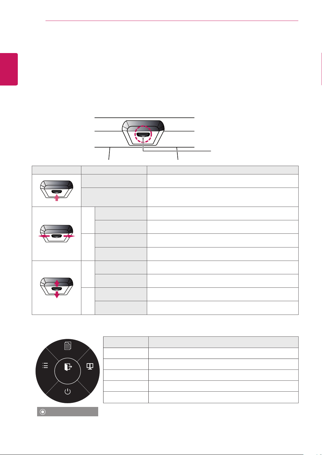
Activating the Main Menu
1
Press the joystick button on the bottom of the monitor.
2
Move the joystick up/down (▲/▼) and left/right(◄/►) to set the options.
3
Press the joystick button once more to exit the main menu.
Joystick
Button
Button Menu Status Description
Main menu disabled Enables the main menu.
Main menu enabled
Exits the main menu.
(Holding down the button to turn off the monitor: You can turn off
the monitor this way at any time, including when the OSD is on)
◄
Main menu disabled Adjusts the monitor volume level.
Main menu enabled Enters the menu features.
►
Main menu disabled Adjusts the monitor volume level.
Main menu enabled Enters the PBP feature.
▲
Main menu disabled Enables the main menu.
Main menu enabled Enters the reader feature.
▼
Main menu disabled Enables the main menu.
Main menu enabled Turns off the monitor.
Main Menu Features
Reader
Menu PBP
Monitor off
Exit
Long press: Monitor off
Main Menu Description
Menu Configures the screen settings.
Reader Adjusts color for comfortable text file reading.
PBP Displays the screens of two input modes on one monitor.
Monitor off Turns off the monitor.
Exit Exits the main menu.
ENGLISH
21
USER SETTINGS
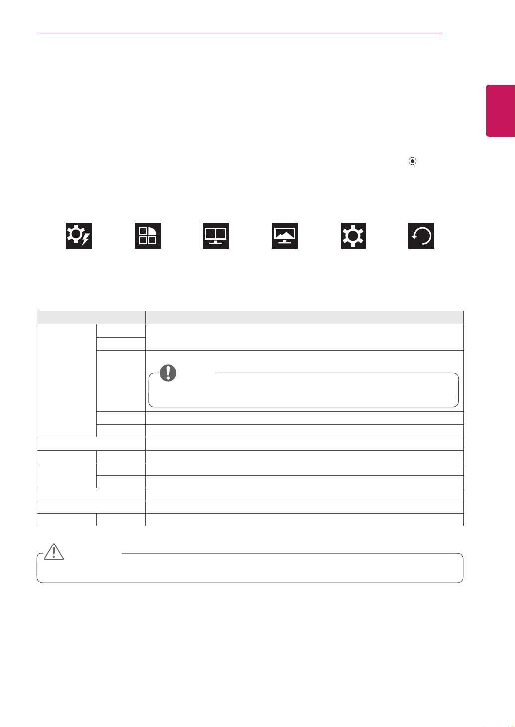
User Settings
Menu Settings
1
To view the OSD menu, press the joystick button at the bottom of the monitor and then enter the
Menu.
2
Configure the options by moving the joystick up/down/left/right.
3
To return to the upper menu or set other menu items, move the joystick to ◄ or pressing ( / OK) it.
4
If you want to exit the OSD menu, move the joystick to ◄ until you exit.
y
When you enter the menu, instructions on how to use the button will appear in the bottom right corner
of the screen.
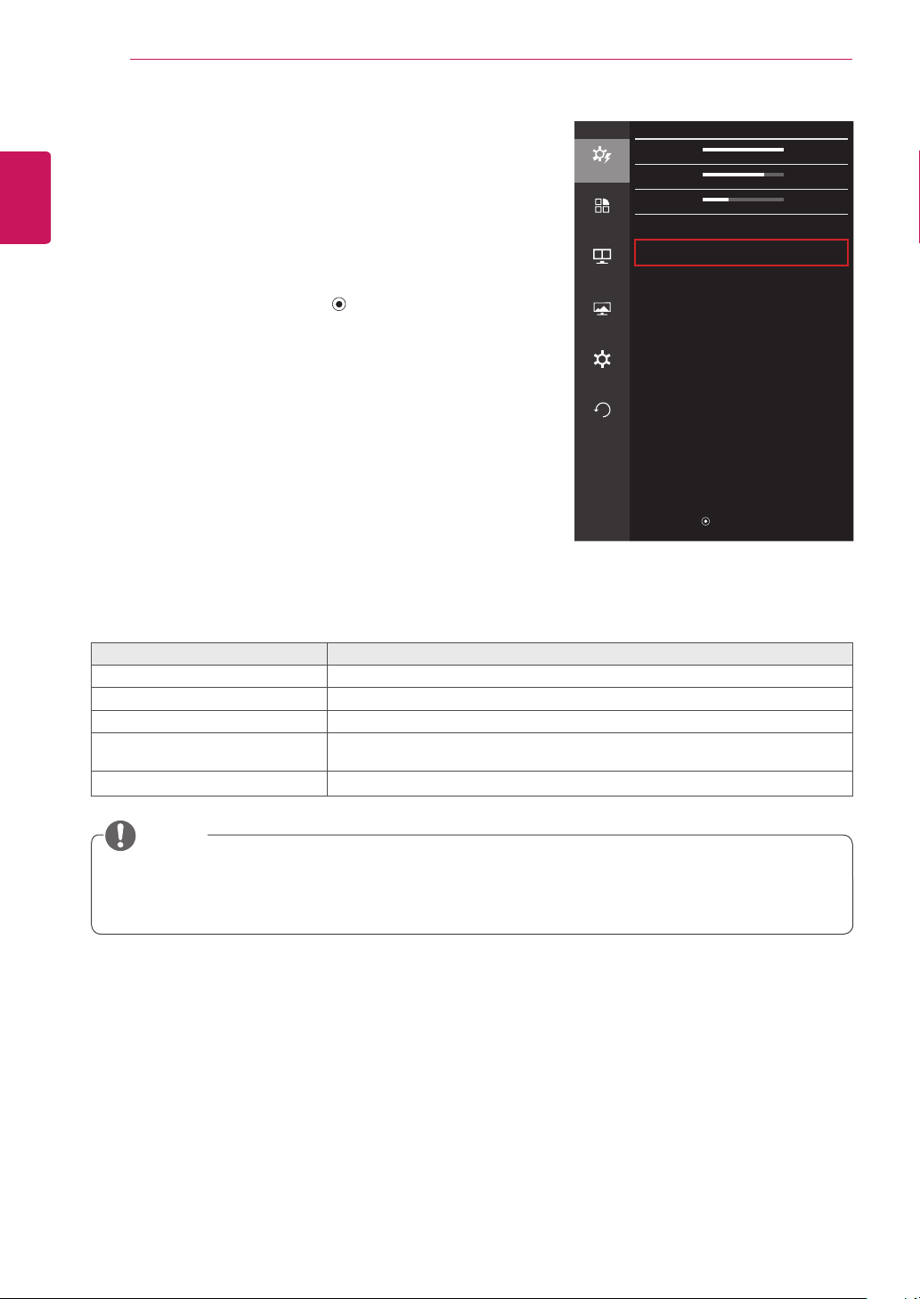
Easy control Function PBP Screen Settings Reset
Each option is described below.
Menu Description
Easy control Brightness
Adjusts the color contrast and brightness of the screen.
Contrast
Volume Adjusts the volume level.
y
You can adjust Mute/ Unmute by moving the joystick button to ▼ in the Volume
menu.
NOTE
Input Selects the input mode.
Ratio Adjusts the aspect ratio of the screen.
Function Adjusts SMART ENERGY SAVING, Calibration and Picture Modes.
PBP PBP Displays the screens of two input modes on one monitor.
Screen Picture Adjusts the Sharpness, Black level and Response Time of the screen.
Color Adjusts Gamma, Color Temperature, Red, Green, Blue and Six Color.
Settings Adjusts Language, Power LED, Automatic Standby, DisplayPort 1.2 and OSD Lock.
Reset Restores the default settings.
◄ Exit Exits the OSD menu.
y
Your monitor’s OSD (On Screen Display) may differ slightly from that shown in this manual.
CAUTION
ENGLISH
22
USER SETTINGS
Ratio
1
To view the OSD menu, press the joystick button at the
bottom of the monitor and then enter the Menu.
2
Go to Easy control > Ratio by moving the joystick.
3
Configure the options following the instructions that appear
in the bottom right corner.
4
To return to the upper menu or set other menu items, move
the joystick to ◄ or pressing ( / OK) it.
5
If you want to exit the OSD menu, move the joystick to ◄
until you exit.
Each option is described below.
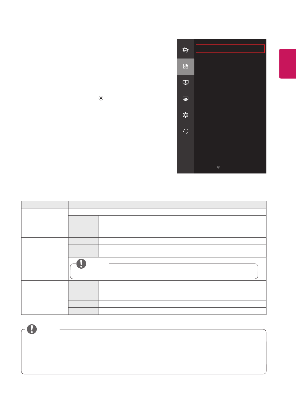
Menu > Easy control > Ratio Description
Wide Displays the video in widescreen, regardless of the video signal input.
Original Displays video according to the aspect ratio of the video signal input.
Cinema 1 Enlarges the screen with an aspect ratio of 21:9. (at 1080p)
Cinema 2 Enlarges the screen with an aspect ratio of 21:9, including the black box at the
bottom for subtitles. (at 1080p)
1:1 The aspect ratio is not adjusted from the original.
y
The display may look the same for Wide, Original, and 1:1 options at the recommended resolution
(3440 x 1440).
y
The ratio is disabled in the interlaced signal.
NOTE
Easy control
Easy control
Brightness
100
>
Contrast 70
>
Function
Volume
30
>
Input HDMI
>
PBP
Ratio Wide
>
Screen
Settings
Reset
▲/▼: Move
/ ►: OK
◄: Back
ENGLISH
23
USER SETTINGS
Function
1
To view the OSD menu, press the joystick button at the
bottom of the monitor and then enter the Menu.
2
Go to Function by moving the joystick.
3
Configure the options following the instructions that appear in
the bottom right corner.
4
To return to the upper menu or set other menu items, move
the joystick to ◄ or pressing ( / OK) it.
5
If you want to exit the OSD menu, move the joystick to ◄
until you exit.
Each option is described below.
Menu > Function Description
SMART ENERGY
SAVING
Conserve energy by using luminance compensation algorithm
High Saves energy using the high-efficiency SMART ENERGY SAVING feature.
Low Saves energy using the low-efficiency SMART ENERGY SAVING feature.
Off Disables the SMART ENERGY SAVING feature.
Calibration On Enables the calibration applied to the monitor.
Off If it is set to Off, the monitor reverts back to the picture quality set before calibra-
tion.
y
Run the True Color Finder program.
NOTE
Picture Mode Custom Allows the user to adjust settings. You can adjust the color mode of the main
menu.
Photo Optimizes the screen for photos.
Cinema Optimizes the screen for videos.
Game Optimizes the screen for games.
Function
Easy control
SMART ENERGY SAVING Low
>
Calibration Off
>
Function
Picture Mode Custom
>
PBP
Screen
Settings
Reset
▲/▼: Move
/ ►: OK
◄: Back
y
Saving Data depends on the panel. So,those values should be different from each panel and panel
vendor. If option of SMART ENERGY SAVING is High or Low, monitor luminance become higher or
lower depend upon source.
y
If option of SMART ENERGY SAVING is High or Low, Picture Mode will automatically be Custom, and
Reader Mode will automatically be Reader Off.
NOTE
ENGLISH
24
USER SETTINGS
PBP
1
To view the OSD menu, press the joystick button at the
bottom of the monitor and then enter the Menu.
2
Go to PBP by movingthe joystick.
3
Configure the options following the instructions that appear in
the bottom right corner.
4
To return to the upper menu or set other menu items, move
the joystick to ◄ or pressing ( / OK) it.
5
If you want to exit the OSD menu, move the joystick to ◄
until you exit.
Each option is described below.
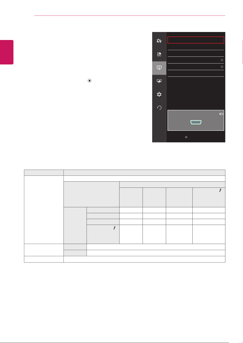
Menu > PBP Description
PBP Displays the screens of two input modes on one monitor.
PBP Connection
Sub Screen (Right)
HDMI 1 HDMI 2 DisplayPort
Thunderbolt
( )
(34UM95 /
34UM94 Model
only)
Main
Screen
(Left)
HDMI 1
-
O
X X
HDMI 2
O - X X
DisplayPort
O O - X
Thunderbolt ( )
(34UM95 /
34UM94 Model
only)
O O X -
Input Main Selects the video signal input of the main screen.
Sub Selects the video signal input of the sub screen.
Audio Changes the audio output in PBP mode.
PBP
Easy control
PBP Off
>
Input
>
Function
Audio HDMI1
>
Swap
PBP
Sub Full
Ratio
>
Screen
Settings
Reset
PBP Preview
HDMI1
▲/▼: Move
/ ►: OK
◄: Back
ENGLISH
25
USER SETTINGS
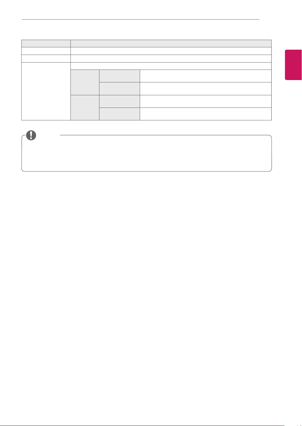
Menu > PBP Description
Swap Toggles between the main screen and sub screen in PBP mode.
Sub Full Converts the sub screen in PBP mode to wide screen.
Ratio Adjusts the aspect ratio of the main screen or sub screen.
Main Wide Displays the video to fit the PBP screen, regardless of the
video signal input.
Original Displays the video in the aspect ratio of the video signal input
on the PBP screen.
Sub Wide Displays the video to fit the PBP screen, regardless of the
video signal input.
Original Displays the video in the aspect ratio of the video signal input
on the PBP screen.
y
When the PBP mode is Off, Input, Audio, Swap, Sub Full, and Ratio menus become disabled. The
Main/Sub options for Ratio become disabled if there is no signal.
y
The optimal resolution for PBP mode is set automatically when PBP mode is set. (34UM95C model
only)
NOTE
ENGLISH
26
USER SETTINGS
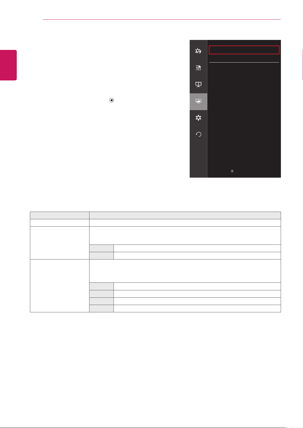
Picture
1
To view the OSD menu, press the joystick button at the
bottom of the monitor and then enter the Menu.
2
Go to Screen > Picture by moving the joystick.
3
Configure the options following the instructions that appear in
the bottom right corner.
4
To return to the upper menu or set other menu items, move
the joystick to ◄ or pressing ( / OK) it.
5
If you want to exit the OSD menu, move the joystick to ◄
until you exit.
Each option is described below.
Menu > Screen > Picture Description
Sharpness Adjusts the sharpness of the screen.
Black Level Sets the offset level (for HDMI only).
• Offset: as a reference for a video signal, this is the darkest color the monitor can dis-
play.
High The picture of the screen gets brighter.
Low The picture of the screen gets darker.
Response Time Sets a response time for displayed pictures based on the speed of the screen. For a nor-
mal environment, it is recommended that you use Middle. For a fast-moving picture, it is
recommended that you use High.
Setting to High may cause image sticking.
High Sets the response time to High.
Middle Sets the response time to Middle.
Low Sets the response time to Low.
Off Does not use the response time improvement feature.
Screen
Easy control
Picture
>
Color
>
Function
PBP
Screen
Settings
Reset
▲/▼: Move
/ ►: OK
◄: Back

ENGLISH
27
USER SETTINGS
Color
1
To view the OSD menu, press the joystick button at the
bottom of the monitor and then enter the Menu.
2
Go to Screen > Color by moving the joystick.
3
Configure the options following the instructions that appear in
the bottom right corner.
4
To return to the upper menu or set other menu items, move
the joystick to ◄ or pressing ( / OK) it.
5
If you want to exit the OSD menu, move the joystick to ◄
until you exit.
Each option is described below.
Menu > Screen > Color Description
Gamma Custom gamma settings: When using the gamma 0, gamma 1 and gamma 2 monitor set-
tings, higher gamma settings mean a brighter image is displayed and vice versa.
Color Temp Custom Selects the factory default picture color.
Warm Sets the screen color to a reddish tone.
Medium Sets the screen color to between a red and blue tone.
Cool Sets the screen color to a bluish tone.
Red You can customize the picture color using Red, Green and Blue colors.
Green
Blue
Six Colors Meets the user requirements for colors by adjusting the tone and saturation of the six colors
(red, green, blue, cyan, magenta and yellow) and then saving the settings.
Hue Adjusts the tone of the screen colors.
Saturation Adjusts the saturation of the screen colors. The lower the value, the less satu-
rated and brighter the colors become. The higher the value, the more saturated
and darker the colors become.
Reset Returns color to the default settings.
Screen
Easy control
Picture
>
Color
>
Function
PBP
Screen
Settings
Reset
▲/▼: Move
/ ►: OK
◄: Back
ENGLISH
28
USER SETTINGS
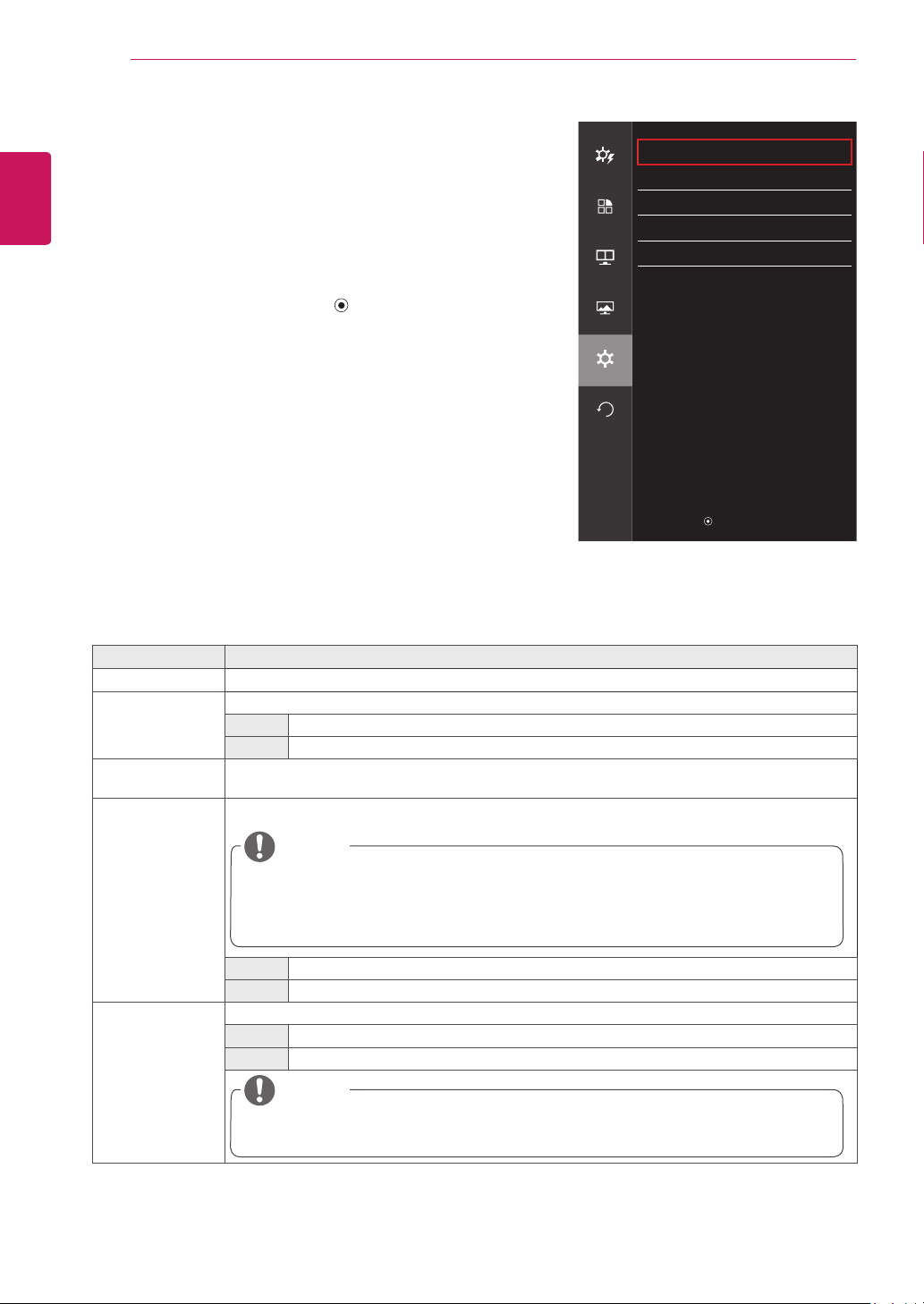
Settings
1
To view the OSD menu, press the joystick button at the
bottom of the monitor and then enter the Menu.
2
Go to Settings by moving the joystick.
3
Configure the options following the instructions that appear in
the bottom right corner.
4
To return to the upper menu or set other menu items, move
the joystick to ◄ or pressing ( / OK) it.
5
If you want to exit the OSD menu, move the joystick to ◄
until you exit.
Each option is described below.
Menu > Settings Description
Language Sets the menu screen to the desired language.
Power LED Turns the power LED on the front of the monitor on or off.
On The power LED turns on automatically.
Off The power LED turns off.
Automatic
Standby
Feature that automatically turns off the monitor when there is no movement on the screen for a
period of time.
DisplayPort 1.2 Enables or disables DisplayPort 1.2.
y
Be sure to configure this option according to the DisplayPort version supported by your
graphics card. Set this option to Disable if your graphics card does not support
DisplayPort 1.2.
y
In order to use 10 bit color in 3440 X 1440 @ 60 Hz, must be set to Enable DisplayPort 1.2.
NOTE
Enable Enables DisplayPort 1.2
Disable Disables DisplayPort 1.2
OSD Lock Prevents incorrect key input.
On Disables key input
Off Enables key input
y
All features are disabled except Brightness, Contrast, Volume, Input, OSD Lock in Settings
and the Exit button.
NOTE
Settings
Easy control
Language English
>
Power LED On
>
Function
Automatic
Standby
Off
>
DisplayPort 1.2 Disable
>
PBP
OSD Lock Off
>
Screen
Settings
Reset
▲/▼: Move
/ ►: OK
◄: Back
ENGLISH
29
USER SETTINGS
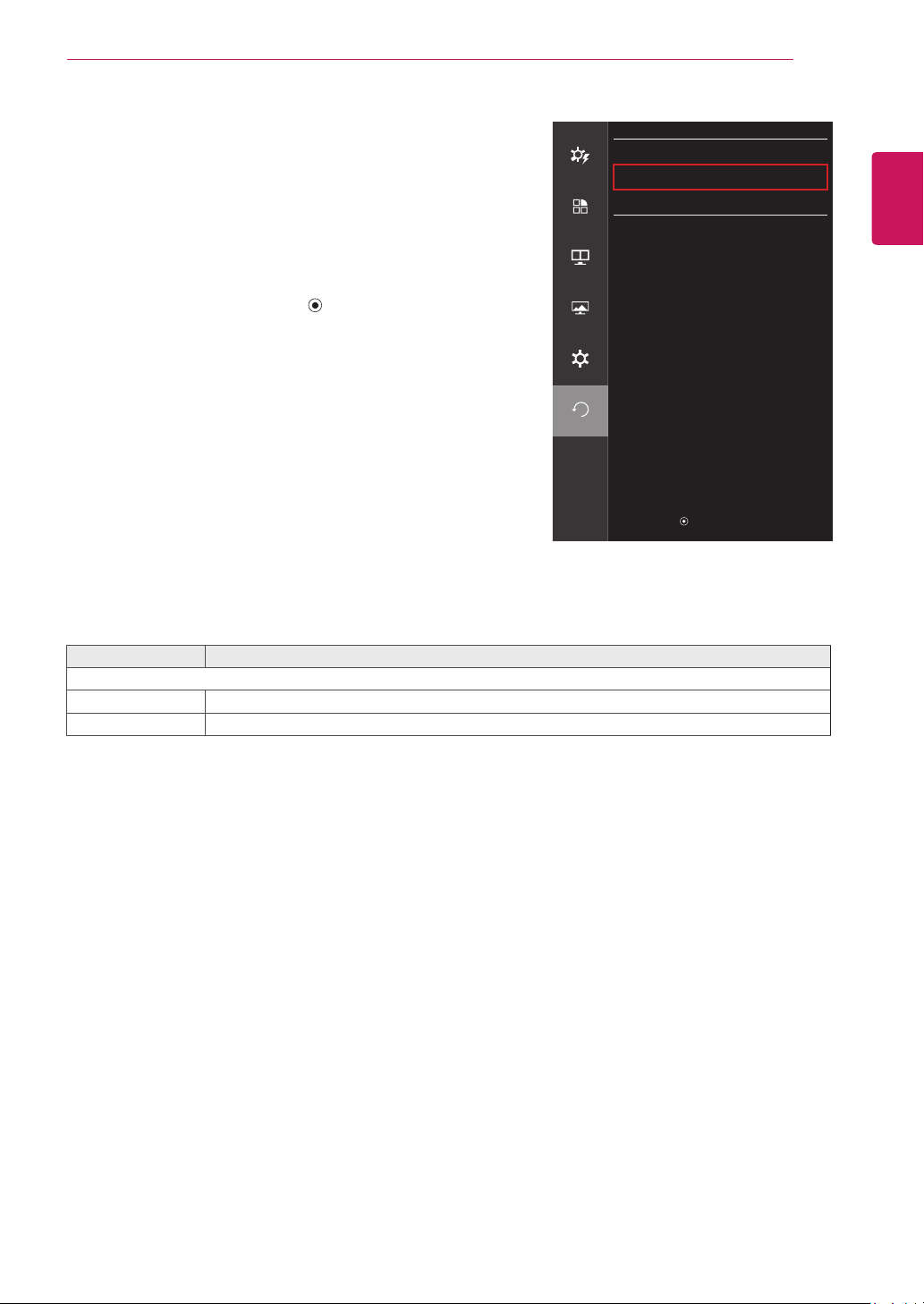
Reset
1
To view the OSD menu, press the joystick button at the
bottom of the monitor and then enter the Menu.
2
Go to Reset by moving the joystick.
3
Configure the options following the instructions that appear in
the bottom right corner.
4
To return to the upper menu or set other menu items, move
the joystick to ◄ or pressing ( / OK) it.
5
If you want to exit the OSD menu, move the joystick to ◄
until you exit.
Each option is described below.
Menu > Reset Description
Do you want to reset your settings?
Reset Restores the default settings.
Cancel Cancel the reset.
Reset
Easy control
Do you want to reset your settings?
Reset
Function
Cancel
PBP
Screen
Settings
Reset
▲/▼:Move
/►:OK
◄:Back
ENGLISH
30
USER SETTINGS
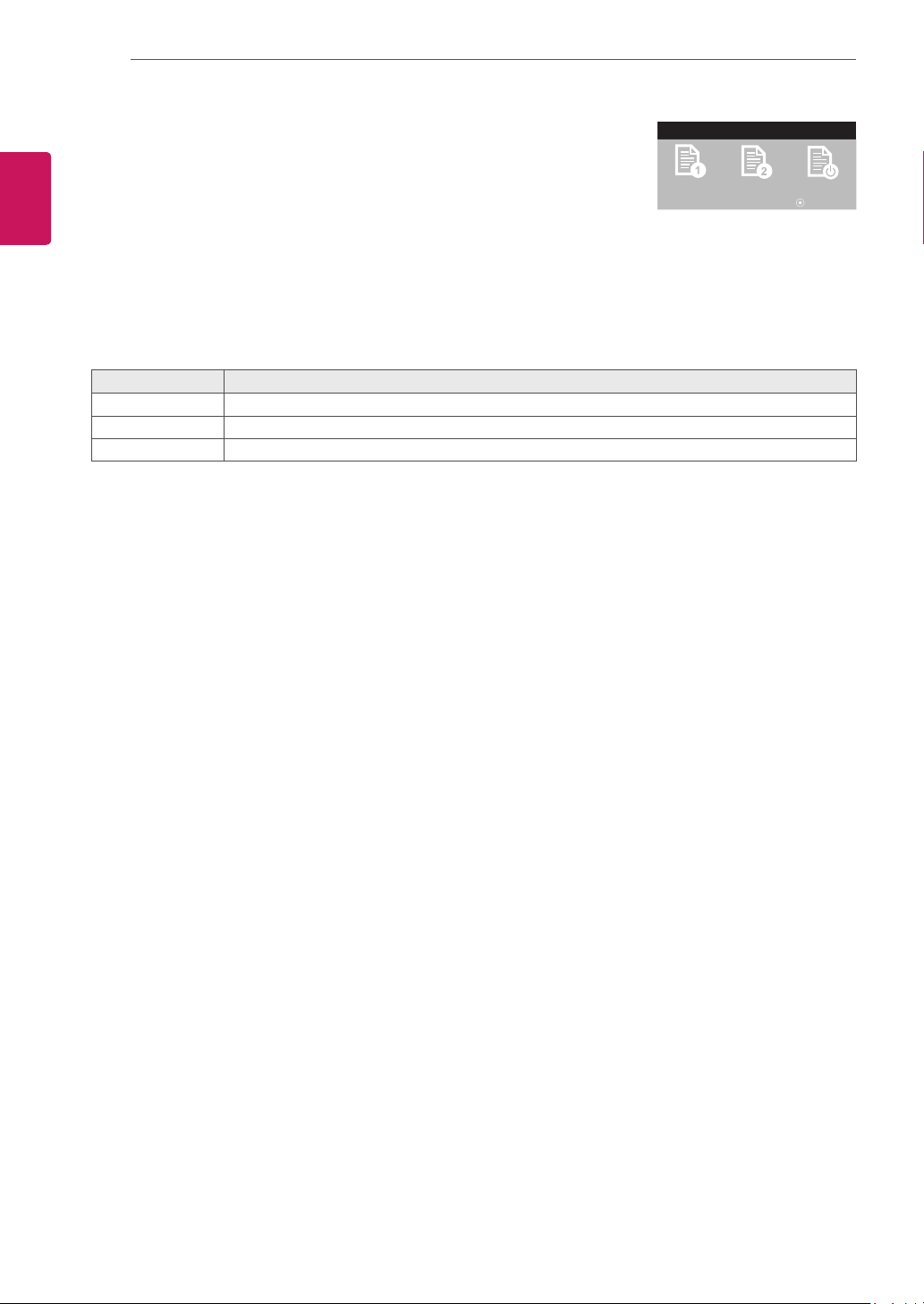
Reader
1
Press the joystick button on the bottom of the monitor.
2
Go to Reader by moving the joystick button to
▲
.
3
Configure the options following the instructions that appear in the bottom.
Each option is described below.
Reader Mode Description
Reader 1 Optimizes the screen for browsing newspapers. You can brighten the screen in the OSD menu.
Reader 2 Optimizes the screen for looking at cartoons. You can brighten the screen in the OSD menu.
Reader Off Reader Mode is off.
Reader Mode
Reader 1
Reader 2
Reader Off
◄ / ► : Change Mode : OK

ENGLISH
31
TROUBLESHOOTING
TROUBLESHOOTING
Nothing is displayed on the screen.
Is the monitor's power cord
plugged in?
y
Check if the power cord is correctly plugged into the power outlet.
Is the power LED on?
y
Check the power cable connection and press the power button.
Is the power on and the power
LED displaying white?
y
Check that the connected input is enabled (Menu - Input).
Is the power LED blinking?
y
If the monitor is in sleep mode, move the mouse, or press any key
on the keyboard, to switch the display on.
y
Check if the computer is turned on.
Is the OUT OF RANGE mes-
sage being displayed?
y
This occurs when signals transferred from the PC (video card) are
out of the horizontal or vertical frequency range of the monitor.
Please see the Product Specification section of this manual to set
the appropriate frequency.
Is the No Signal message be-
ing displayed?
y
This is displayed when the signal cable between the PC and the
monitor is missing or disconnected. Check the cable and reconnect
it.
The 'OSD Locked' message is being displayed.
Are some functions not avail-
able when you press the Menu
button?
y
The OSD is locked. Go to Menu > Settings and set OSD Lock to Off.
The screen retains an image.
Does image sticking occur even
when the monitor is turned off?
y
Displaying a still image for a prolonged time may cause damage to
the screen, resulting in the retention of the image.
y
To extend the lifetime of the monitor, use a screensaver.
Screen display is unstable and shaky / Images displayed on the monitor leave shadow trails.
Did you select the appropriate
resolution?
y
If the selected resolution is HDMI 1080i 60/50 Hz (interlaced), the
screen may be flickering. Change the resolution to 1080P or the
recommended resolution.
y
Vertical Frequency: In order to display an image, the screen must be refreshed dozens of times per
second, like a fluorescent lamp. The number of times the screen is refreshed per second is called
vertical frequency, or refresh rate, and is represented by Hz.
y
Horizontal Frequency: The time it takes to display one horizontal line is called the horizontal cycle. If
1 is divided by the horizontal interval, the result is the number of horizontal lines displayed per second.
This is called horizontal frequency and is represented by kHz.
NOTE
ENGLISH
32
TROUBLESHOOTING
y
Check if the video card's resolution or frequency is within the range allowed by the monitor and set it to
the recommended (optimal) resolution in Control Panel > Display > Settings.
y
Not setting the video card to the recommended (optimal) resolution may result in blurred text, a dimmed
screen, a truncated display area or misalignment of the display.
y
The setting methods may be different depending on the computer or operating system, and some reso-
lutions may not be available depending on the performance of the video card. If this is the case, contact
the manufacturer of the computer or video card for assistance.
y
Some video cards may not support 3440 x 1440 resolution. If the resolution cannot be displayed, con-
tact the manufacturer of your video card.
NOTE
The display color is abnormal.
Does the display appear discol-
ored (16 colors)?
y
Set the color to 24 bit (true color) or higher. In Windows, go to Con-
trol Panel > Display > Settings > Color Quality.
Does the display color appear
unstable or monochrome?
y
Check if the signal cable is connected properly. Reconnect the cable
or reinsert the PC's video card.
Are there spots on the screen?
y
When using the monitor, pixilated spots (red, green, blue, white or
black) may appear on the screen. This is normal for an LCD screen.
It is not an error, nor is it related to the monitor's performance.
ENGLISH
33
PRODUCT SPECIFICATION
PRODUCT SPECIFICATION
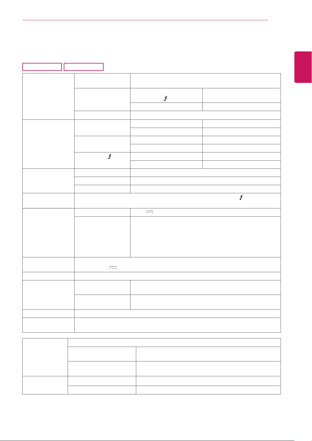
34UM95
34UM94
LCD Screen Type TFT (Thin Film Transistor)
LCD (Liquid Crystal Display) Screen
Color Depth HDMI IN 1 / HDMI IN 2 /
Thunderbolt ( )
8-bit color is supported.
DP (DisplayPort) 10-bit color is supported.
Pixel Pitch 0.2325 mm x 0.2325 mm
Resolution HDMI Max Resolution 3440 x 1440 @ 50 Hz
Recommended Resolution 3440 x 1440 @ 50 Hz
DisplayPort Max Resolution 3440 x 1440 @ 60 Hz
Recommended Resolution 3440 x 1440 @ 60 Hz
Thunderbolt ( )
Max Resolution 3440 x 1440 @ 60 Hz
Recommended Resolution 3440 x 1440 @ 60 Hz
Video Signal Horizontal Frequency 30 kHz to 90 kHz
Vertical Frequency 56 Hz to 61 Hz
Synchronization Separate Sync.
Input Connector
HDMI IN 1, HDMI IN 2, DP (DisplayPort) IN, H/P OUT, Thunderbolt ( ), USB UP,
USB IN 1, 2, 3
Power Sources Power Rating 19 V 6.5 A
Power Consumption
(Typical)
Operating Mode: 80 W (Typical, USB excluded) (Outgoing
Condition)
Sleep Mode ≤ 1.2 W
Off Mode ≤ 0.5 W (Only 34UM95-PD, 34UM94-PD)
Off Mode ≤ 0.3 W (DC switch is off. (Only 34UM95-PE,
34UM94-PE))
AC/DC Adapter LCAP31 type, manufactured by Lienchang
Output: 19 V 7.37 A
Stand Angle Forward/Backward: -5° to 15° (Head)
Environmental Con-
ditions
Operating Conditions Temperature 0°C to 40°C (32 °F to 104°F)
Humidity Less than 80%
Storing Conditions Temperature -20°C to 60°C (-4 °F to 140°F)
Humidity Less than 85%
Audio Output 7 W + 7 W
Supported
Operating System
Win 7, Win 8.1, New Mac Pro (Over Mac OS 10.9.1)
Dimensions Monitor Size (Width x Height x Depth)
With Stand 829.9 mm x 468.9 mm x 172.9 mm
(32.6 inch x 18.4 inch x 6.8 inch)
Without Stand 829.9 mm x 379.8 mm x 82.9 mm
(32.6 inch x 14.9 inch x 3.2 inch)
Weight (Without
Packaging)
With Stand 7.7 kg (16.9 lb)
Without Stand 6.7 kg (14.7 lb)
Specifications are subject to change without notice.
ENGLISH
34
PRODUCT SPECIFICATION
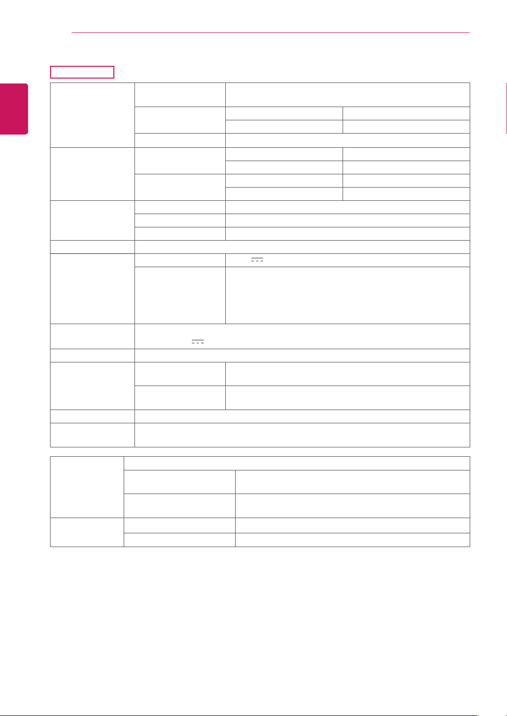
34UM95C
LCD Screen Type TFT (Thin Film Transistor)
LCD (Liquid Crystal Display) Screen
Color Depth HDMI IN 1 / HDMI IN 2 8-bit color is supported.
DP (DisplayPort) 10-bit color is supported.
Pixel Pitch 0.2325 mm x 0.2325 mm
Resolution HDMI Max Resolution 3440 x 1440 @ 50 Hz
Recommended Resolution 3440 x 1440 @ 50 Hz
DisplayPort Max Resolution 3440 x 1440 @ 60 Hz
Recommended Resolution 3440 x 1440 @ 60 Hz
Video Signal Horizontal Frequency 30 kHz to 90 kHz
Vertical Frequency
56 Hz to 61 Hz
Synchronization Separate Sync.
Input Connector HDMI IN 1, HDMI IN 2, DP (DisplayPort) IN, H/P OUT, USB UP, USB IN 1, 2, 3
Power Sources Power Rating 19 V 4.1 A
Power Consumption
(Typical)
Operating Mode: 70 W (Typical, USB excluded) (Outgoing
Condition)
Sleep Mode ≤ 1.2 W
Off Mode ≤ 0.5 W
Off Mode ≤ 0.3 W (DC switch is off.)
AC/DC Adapter ADS-110CL-19-3 190110G type, manufactured by Honor
Output: 19 V 5.79 A
Stand Angle Forward/Backward: -5° to 15° (Head)
Environmental Con-
ditions
Operating Conditions Temperature 0°C to 40°C (32 °F to 104°F)
Humidity Less than 80%
Storing Conditions Temperature -20°C to 60°C (-4 °F to 140°F)
Humidity Less than 85%
Audio Output 7 W + 7 W
Supported
Operating System
Win 7, Win 8.1, New Mac Pro (Over Mac OS 10.9.1)
Dimensions Monitor Size (Width x Height x Depth)
With Stand 829.9 mm x 468.9 mm x 172.9 mm
(32.6 inch x 18.4 inch x 6.8 inch)
Without Stand 829.9 mm x 379.8 mm x 82.9 mm
(32.6 inch x 14.9 inch x 3.2 inch)
Weight (Without
Packaging)
With Stand 7.7 kg (16.9 lb)
Without Stand 6.7 kg (14.7 lb)
Specifications are subject to change without notice.
ENGLISH
35
PRODUCT SPECIFICATION
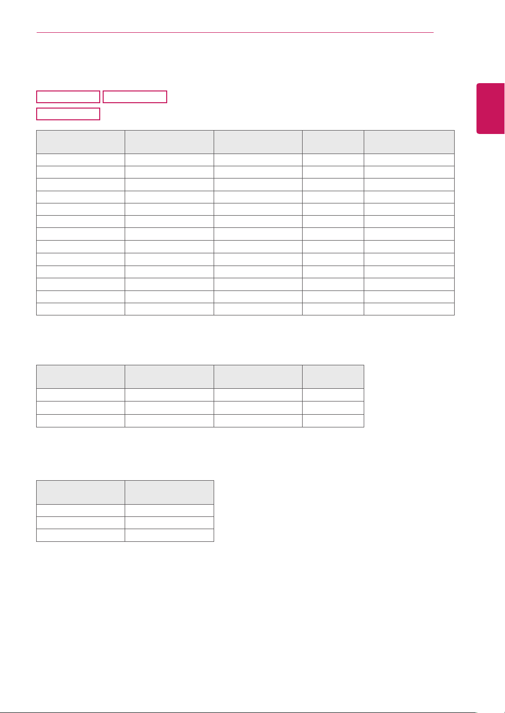
Factory Support Mode
34UM95
34UM94
(Preset Mode, HDMI/ DisplayPort/ Thunderbolt PC)
34UM95C
(Preset Mode, HDMI/ DisplayPort PC)
Preset Mode
Horizontal Frequency
(kHz)
Vertical Frequency
(Hz)
Polarity (H/V) Remarks
640 x 480 31.469 59.94 -/-
800 x 600 37.879 60.317 +/+
1024 x 768 48.363 60 -/-
1152 x 864 54.347 60.05 +/+
1280 x 720 45 60 +/+
1280 x 1024 63.981 60.02 +/+
1600 x 900 60 60 +/+
1680 x 1050 65.29 59.954 -/+
1920 x 1080 67.5 60 +/-
2560 x 1080 66.7 60 -/+
3440 x 1440 43.82 29.99 +/+
3440 x 1440 73.68 49.99 +/+
3440 x 1440 88.82 59.97 +/+ HDMI is not supported.
HDMI Timing (Video)
Preset Mode
Horizontal Frequency
(kHz)
Vertical Frequency
(Hz)
Remarks
480P 31.5 60
720P 45 60
1080P 67.5 60
Power LED
Mode LED Color
On Mode White
Sleep Mode Flashing White
Off Mode Off
ENGLISH
36
PROPER POSTURE
PROPER POSTURE
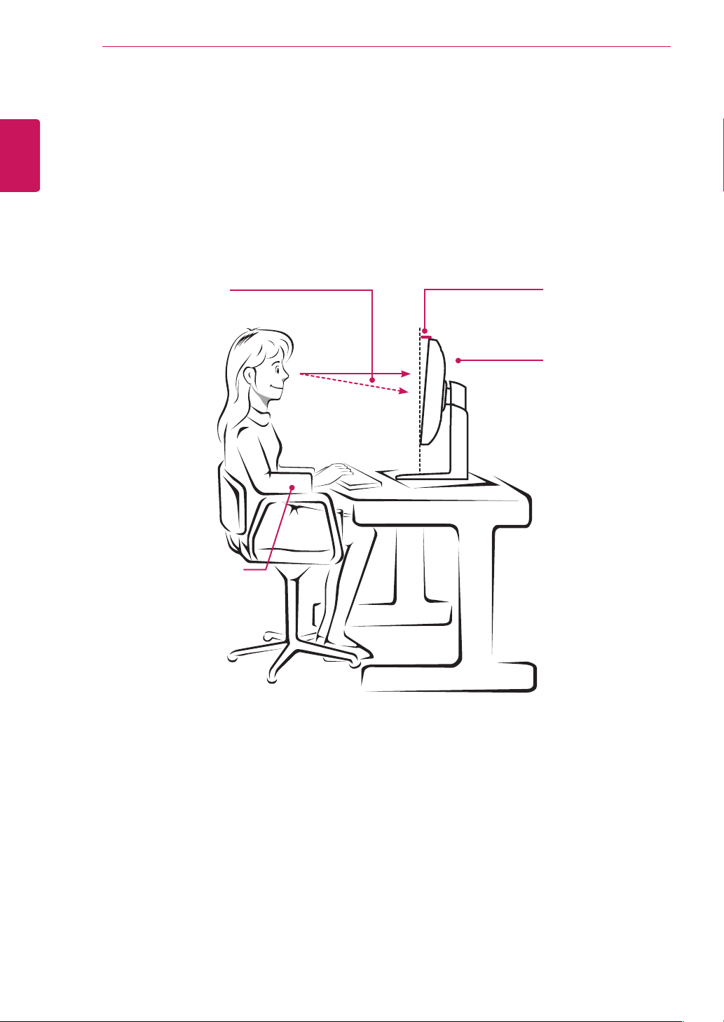
Proper Posture for Using the Monitor
Adjust the screen so that you can comfortably look at it at a slight downward angle from your natural eye
level.
y
Take a break for approximately 10 minutes every hour to reduce any fatigue caused by prolonged
usage.
y
Adjust the stand angle from -5° to 15° to obtain the best view of the screen.
You should be looking
slightly down at the
screen.
Place your hands gently
on the keyboard,
keeping your arms bent at
the elbows
and extended horizontally
in front of you.
Stand Angle
-5° to 15°
Adjust the position of
the screen to mini-
mize reflections.


This device meets the EMC requirements for
home appliances (Class B) and is intended for
home usage. This device can be used in all
regions. Read the owner's manual (CD) carefully
and keep it at hand. Please note that the label
attached to the product provides information for
technical support.
Model
Serial No.
Declaration of Conformity
Trade Name: LG
Model: 34UM95, 34UM94, 34UM95C
Responsible Party: LG Electronics Inc.
Address: 1000 Sylvan Ave.
Englewood Cliffs NJ 07632
U.S.A
TEL: 201-266-2534
ENERGY STAR is a set of power-saving guidelines
issued by the U.S.Environmental Protection
Agency (EPA).
Refer to ENERGY STAR.gov for more
information on the ENERGY STAR program.
As an ENERGY STAR Partner LGE
U. S. A., Inc. has determined that this
product meets the ENERGY STAR
guidelines for energy efficiency.