
Loading ...
Loading ...
Loading ...
9
The C8 can accept the analog input from a wide
variety on components such as CD players, tuners,
and turntables. There are two sets of unbalanced
inputs dedicated for turntable connections which
allow customization of the input level. See Phono
Adjustments on page 28.. The signal strength from
phono cartridges vary and are lower than the line
level received from most other components. The
turntable will also have a ground connection which
should be secured to the C8’s GND Binding Post to
eliminate ground hum. Turn the Binding Post
counterclockwise to loosen and attach the ground
wire. Turn the Binding Post clockwise to secure the
ground connection.
The MC PHONO INPUT should be used for low
output Moving Coil Cartridges. The MM PHONO
INPUT should be used for Moving Magnet and high
output Moving Coil Cartridges.
Balanced/XLR Input and Output
The BALANCED INPUT allows a source to be
connected using XLR (balanced) cables if the
source has this option.
XLR cables can also be used to connect the C8 to an
amplier. OUTPUT1 has a pair of XLR connectors
as well as a pair of RCA connectors. Both outputs
can be used simultaneously if desired as in the case
of bi-amping. To use the XLR output, connect the
BAL R to the right input of your amplier and BAL
L to the amplier’s left input.
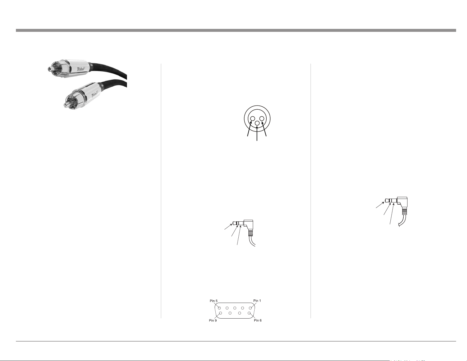
Below is the Pin conguration for the XLR
Balanced Input and Output Connectors on the C8.
Refer to the diagrams for connections:
PIN 1: Shield/Ground
PIN 2: + Signal
PIN 3: - Signal
RS232
The RS232 jack is used to connect the C8 to
automation controller devices with RS232
connectors. To utilize this feature, you will need an
appropriate RS232 Data Cable. The RS232 Data
Cable should be an 1/8 inch (3.5mm) stereo mini
phone plug to a subminiature DB9 connector.
RS232 DB9 Connector Pin Layout
1. N/C (no connection) 6. N/C
2. Data In (RXD) 7. N/C
3. Data Out (TXD) 8. N/C
4. N/C 9. N/C
5. Gnd
Typical RS232 settings are:
• 8 data bits, no parity and one stop bit
• Baud rate xed at 115,200 bits per second
The baud rate can be changed in the Setup. See
“RS232 Setup” on page 14.
Wired IR Input
The IR Input allows an external IR receiver to be
attached to the C8. The Input is labeled IR IN. By
attaching an IR receiver using a 3.5mm cable (see
Figure 09), the C8’s Remote Control can be used in
another location without a line-of-sight to the C8’s
front IR sensor.
IR Data
Control
Ground
N/C
If using an external IR receiver for the MAIN
ZONE in the same room as the C8, you may wish
to disable the front IR sensor. This will avoid
potential timing issues of receiving the Remote
Control’s commands from two different Inputs.
The front IR can be turned on/off by doing the
following:
• Press and Hold the Left Knob for two seconds
• Turn the Left Knob to the menu choice
“SETUP: Front IR”
(Continued on page 11)
Figure 05– RCA/Phono Plugs
PIN 1
PIN 2
PIN 3
Figure 06– XLR pin diagram
Figure 07– Mini plug for RS232 connection
Data In
(DB9-pin2)
Ground
(DB9-pin5)
Data Out
(DB9-pin3)
Figure 08– DB9 connector pin layout
Figure 09– IR 3.5mm connector
Loading ...
Loading ...
Loading ...