Loading ...
Loading ...
Loading ...
A
C
D
B
8”
8”
8”
8”
3”
14”
12”
5”
A
30”
2”
2”
18”
Min.
30”
Min.
13”
Max
1/4”
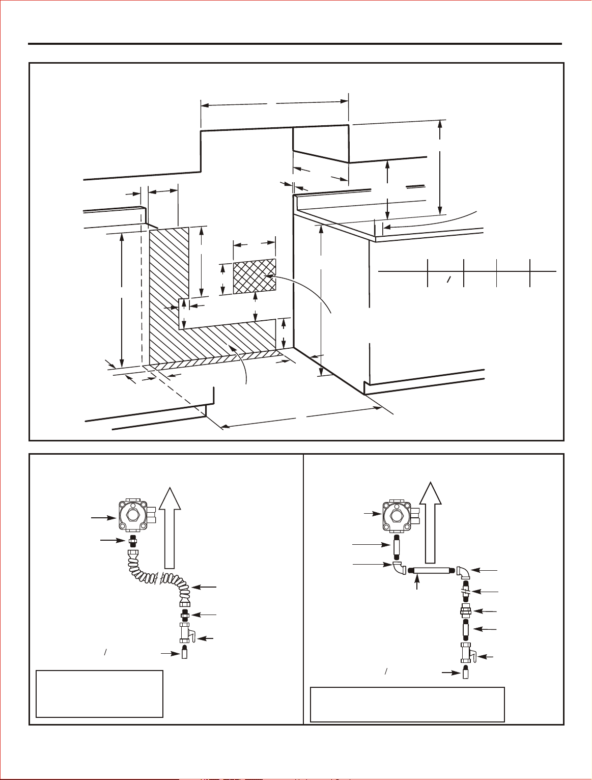
36”
Minimum
distance to
walls above
the cooktop on
each side
Electrical
Connection
Area
Gas
Hookup
Area
Check local codes
before making
connections.
Models A B C D
24” Wide
24 ”
3
8
2” 3” 5½”
NOTE: Recommended gas
hook-up locations behind
range. Gas fittings and shuf-off
cook shoul NOT protude
more than 2” from the wall to
allow the range to fit against
the wall.
RECOMMENDED GAS AND ELECTRIC SUPPLY LOCATION
FLEXIBLE CONNECTOR
HOOKUP (Example)
RIGID PIPE HOOKUP (Example)
Pressure
regulator
Pressure
regulator
Adapter
1 2” or 3/4” Gas pipe
Flex connector
(4½ ft. max.)
Adapter
Gas shut-off valve
Black iron
pipe 4½”
90° Elbow
Nipple (may not
be needed)
1 2” or 3/4” Gas pipe
Gas shut-off
valve
90° Elbow
Black iron
pipe
Union
Nipple
Gas Flow into Range
Gas Flow into Range
Installer: lnform the
consumer of the location
of the gas shut-off valve.
Installer: lnform the consumer of the
location of the gas shut-off valve.
Installation Instructions
27
1” = 2.5 cm.
1’ = 0.3 m.
Loading ...
Loading ...
Loading ...