Loading ...
Loading ...
Loading ...
60 Outdoor Unit
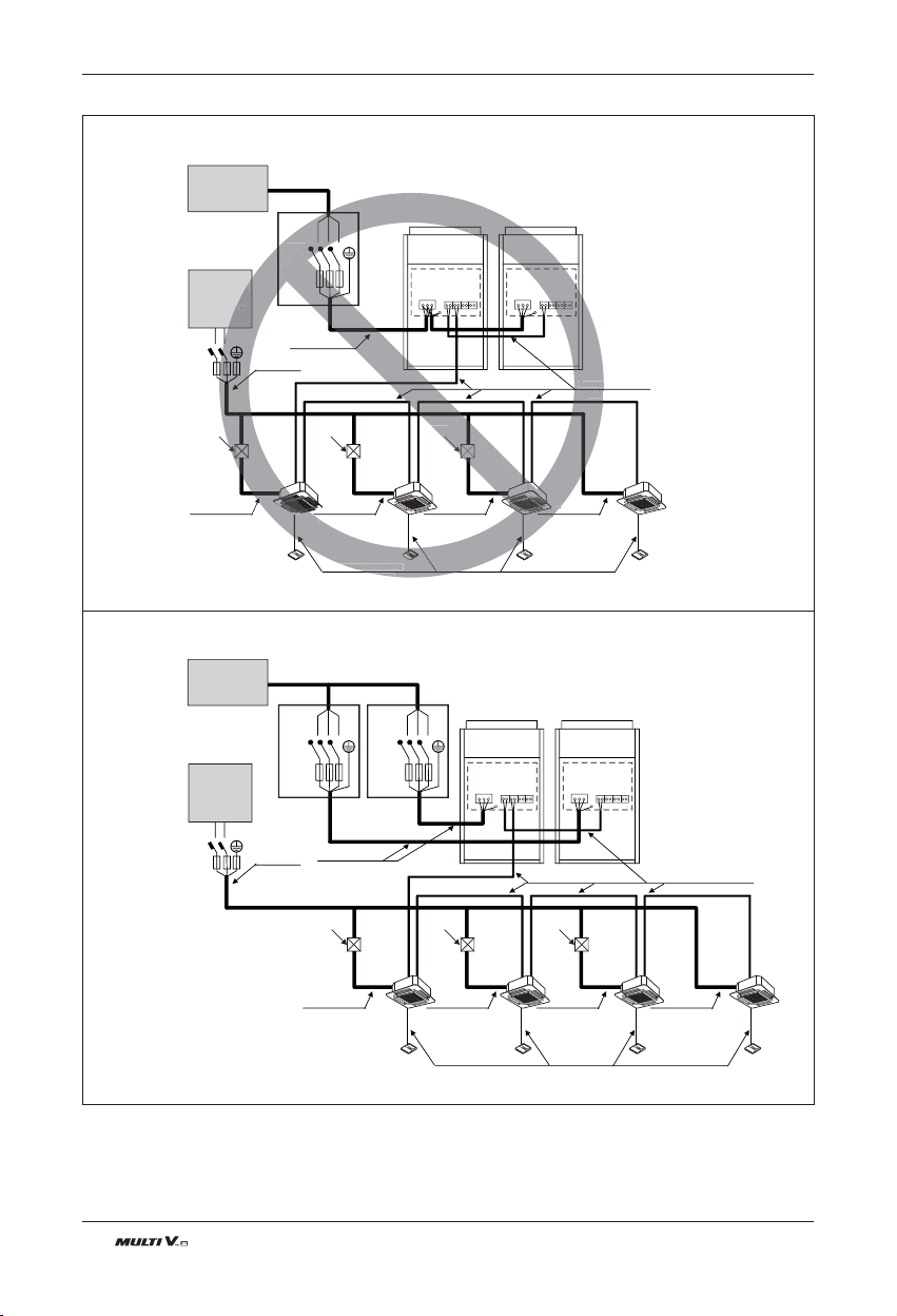
■ Do not install the power source connected in series between the units.
■ Be sure that the power source is supplied to Each outdoor unit individually.
R S T
Switch
Communication Line
(2 Wires Cable)
Power Line
(3 Wires Cable)
Communication Line
(3 Wires Cable)
Power Line
(2 Wires Cable)
Power Line
(2 Wires Cable)
Power Line
(2 Wires Cable)
Power Line
(2 Wires Cable)
Power Line
(2 Wires Cable)
[Master]
[Indoor Units]
Power supply
3 Phase 3 Wires
60Hz 208/230V
Power Supply
1phase 60Hz
220~240V
(Main Switch)
[Slave]
Communication Line
(2 Wires Cable)
Power Line
(3 Wires Cable)
Communication Line
(3 Wires Cable)
Power Line
(2 Wires Cable)
Power Line
(2 Wires Cable)
Power Line
(2 Wires Cable)
Power Line
(2 Wires Cable)
Power Line
(2 Wires Cable)
[Master]
[Indoor Units]
Power supply
3 Phase 3 Wires
60Hz 208/230V
Power Supply
1phase 60Hz
220~240V
(Main Switch)
[Slave]
Pull Box
(Installer option)
Pull Box
(Installer option)
Pull Box
(Installer option)
Pull Box
(Installer option)
Pull Box
(Installer option)
Pull Box
(Installer option)
R
S
T
S
witch
Commu
(2 W
ommunication Line
Cable)
(2
Pow
(2 W
[M
aster
]
y
Hz
0V
ption)
Pull Box
aller option)
R S T
Switch
R S T
Switch
L
N
ELCB
ELCB
L
N
ELCB ELCB
ELCB
n 2 Outdoor Units - 3Ø, 208/230V
Electrical Wiring
Note
1) Field Wiring diagram is to be used as a guidelineonly. Wiring should comply with applicable local and national codes
2) ELCB must have function to prevent electrical short and over current at the same time .
3) Use copper wires only.
4) Unit must be grounded in compliance with the applicable local and national codes.
5) ELCB and fuse/breaker must install to the power line
Loading ...
Loading ...
Loading ...