Loading ...
Loading ...
Loading ...
4
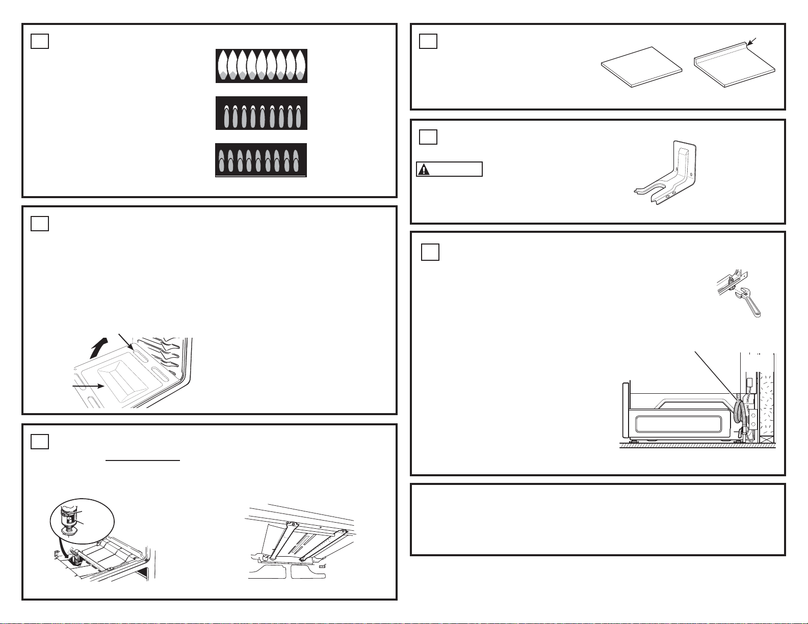
CHECK SURFACE BURNERS
Push and turn knob to LITE position. You will hear
a clicking sound indicating proper operation of
the spark module. Once the air has been purged
from the supply lines, burners should light within 4
seconds. After burner lights, rotate knob out of the
LITE position. Try each burner in succession until
all burners have been checked.
Quality of Flames
The flame quality of the burners needs to be
determined visually.
If burner flames look like (A), call for service.
Normal burner flames should look like (B) or (C),
depending on the type of gas you use
With LP gas, some yellow tipping on outer cones
is normal.
5
CHECK BAKE AND BROIL
BURNERS
To remove the oven bottom:
A. Remove the screws holding down rear of the
oven bottom.
B. Grasp the oven bottom at rear slots on each
side.
C. Lift the rear of the oven bottom and slide it
back until it clears the lip of the range frame
at the front. Then lift bottom up and out.
Set Bake function to 350°F. Burner should
light in 30 to 90 seconds.
Check Flame Quality.
• Flames should have approximately 1” blue
cones.
• Natural gas should burn with no yellow
flames.
• LP gas flames have slight yellow tips
• After warming up, the flame should not lift
off the burner.
Check broil burner using the same method as
the bake burner.
8
INSTALL AND CHECK
ANTI-TIP DEVICE
WARNING
Never completely remove the
leveling leg as the range will not be secured to
the anti-tip device properly.
Follow instructions supplied with ANTI-TIP bracket
WHEN ALL HOOKUPS ARE
COMPLETED
Make sure all controls are left in the off position.
Make sure the flow of combustion and ventilation
air to the range is unobstructed.
Check that all packing materials and tape have
been removed. This will include tape on metal
panel under control knobs (if applicable), adhesive
tape, wire ties, cardboard and protective plastic.
Failure to remove these materials could result in
damage to the appliance once the appliance has
been turned on and surfaces have heated.
&6RIWEOXHIODPHV³
Normal for natural gas
(B) Yellow tips on
RXWHUFRQHV³
Normal for LP gas
$<HOORZIODPHV³
Call for service
6
ADJUST BAKE BURNER AIR
SHUTTER IF NECESSARY
To adjust the flow of air to the bake burner,
loosen the Phillips head screw and rotate the
shutter as needed.
A. If the flames are yellow, open shutter more
than the original setting.
B. If the flames lift off the burner, close the air
shutter more than the original setting.
Check flames again and adjust further if
necessary. Replace oven bottom.
The dual broil burner air shutter is NOT adjustable.
Air
shutter
Loosen
Oven bottom
Anti-Tip Bracket
Kit Included
Slots
Bake Burner
9
SLIDE RANGE INTO OPENING
A. Position the range in front of the cabinet opening. Measure from the floor to
the top of the countertop at the rear of the cabinet near the anti-tip bracket. If
necessary, adjust the unit by carefully screwing in or out the leveling legs until
the cooktop overhang matches the countertop height at the rear (There will not
be access to the rear leveling legs once installed).
B. Push while lifting the range into the opening until the range is within 2” (5.1 cm) of
engaging the anti-tip bracket.
C. Plug the range cord into the receptacle. Locate the
flexible gas line in back of the range in a manner
that it will not touch or be moved by the drawer (if
provided). Carefully push the range into the opening
until the unit is fully seated in to the cabinet. There
will be approximately a ¼” gap between the unit and
back wall.
D. Carefully screw in the front two leveling legs until the
cooktop overhand touches the countertop.
E. Look under the unit and verify that the rear leg is fully
engaged with the anti-tip device. If not, remove the
unit and adjust the height of the rear leg so that it is
properly engaged.
Side View
Rear
Wall
Storage Drawer
Position gas line so that there is no
interference with the storage drawer
Dual Broil Burner
(NOT ADJUSTABLE)
7
INSTALL CORNER TRIM KIT
(OPTIONAL)
The corner trim kit is intended to fill in the
side space in installations without an upswept
countertop. Refer to installation instructions
included with kit.
No upsweep
(Install Kit)
With upswept countertop
(Do not install kit)
Upsweep
INSTALLATION INSTRUCTION
31-10902-5 07-16 GEA
PGS920
Loading ...
Loading ...
Loading ...