Loading ...
Loading ...
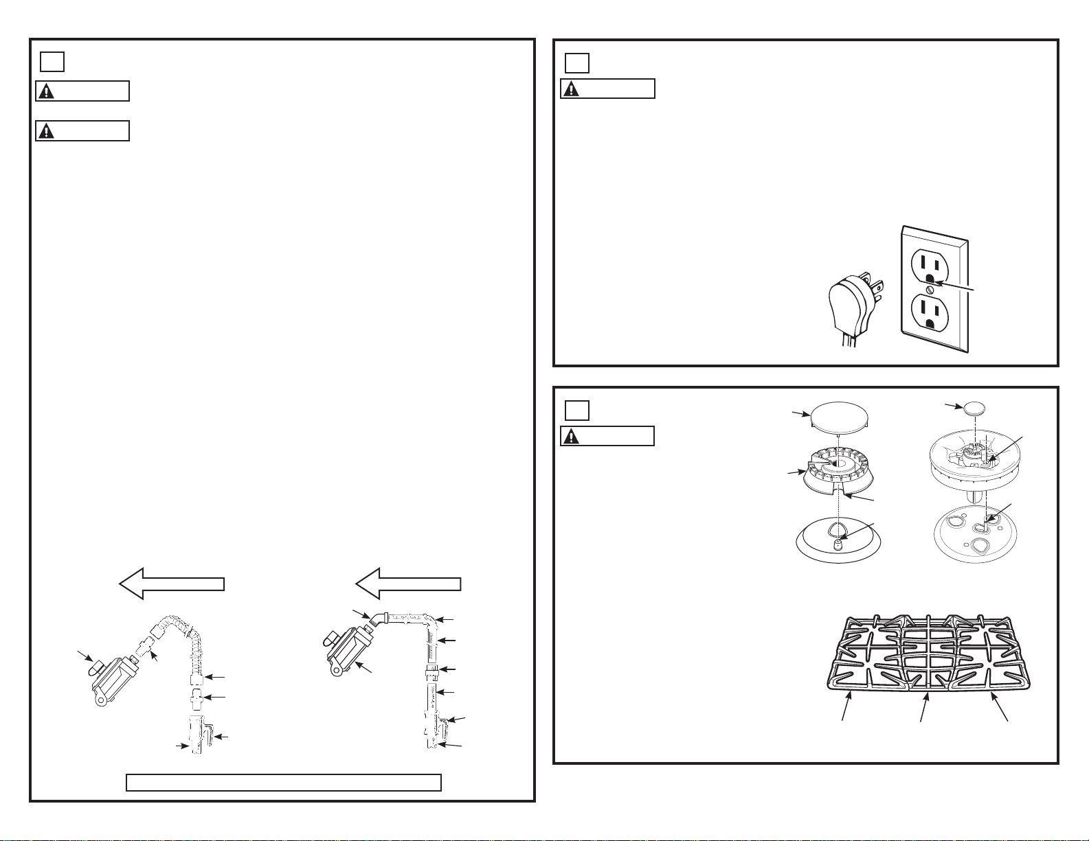
CONNECTOR HOOKUP
Pressure
regulator
Gas Flow into Range Gas Flow into Range
Flex
connector
(6 ft. max.)
Adapter
Installer: Inform the consumer of the location of the gas shut-off valve.
1/2” or 3/4”
Gas pipe
Adapter
Gas
shut-off
valve
Pressure
regulator
Elbow
Elbow
Nipple
Union
Nipple
Gas
shut-off
valve
1/2” or 3/4”
Gas pipe
Flexible
Option
Rigid Pipe
Option
1
GAS SUPPLY
WARNING Fire Hazard: Do not use a
flame to check for gas leaks.
WARNING Explosion Hazard: Do not
exceed 25 ft-lbs of torque when making gas
line connections. Overtightening may crack
the pressure regulator resulting in fire or
explosion hazard.
Gas Pressure Regulator
You must use the gas pressure regulator supplied
with this range. For proper operations the inlet
pressure to the regulator should be as follows:
Natural Gas:
Minimum pressure: 6” of Water Column
Maximum pressure: 13” of Water Column
LP Gas:
Minimum pressure: 11” of Water Column
Maximum pressure: 13” of Water Column
If you are not sure about the inlet pressure
contact local gas supplier.
Shut off the main gas supply valve before
disconnecting the old range and leave it off
until the new hook-up has been completed.
Don’t forget to relight the pilot on other gas
appliances when you turn the gas back on.
Because hard piping restricts movement of
the range, the use of a CSA International-
certified flexible metal appliance connector is
recommended unless local codes require a hard-
piped connection.
If the hard piping method is used, you must
carefully align the pipe; the range cannot be
moved after the connection is made.
To prevent gas leaks, put pipe joint compound on,
or wrap pipe thread tape with Teflon* around, all
male (external) pipe threads.
A. Install a manual shut-off valve in the gas line
in an easily accessed location outside of the
range. Make sure everyone operating the
range knows where and how to shut off the
gas supply to the range.
B. Install male 1/2” flare union adapter to the 1/2”
NPT internal thread at inlet of regulator. Use a
backup wrench on the regulator fitting to avoid
damage.
C. Install male 1/2” or 3/4” flare union adapter to
the NPT internal thread of the manual shut-off
valve, taking care to back-up the shut-off valve
to keep it from turning.
D. Connect flexible metal appliance connector
to the adapter on the range. Position range to
permit connection at the shut-off valve.
E. When all connections have been made, make
sure all range controls are in the off position
and turn on the main gas supply valve.
Use a liquid leak detector at all joints and
connections to check for leaks in the system.
When using pressures greater than 1/2 psig
to pressure test the gas supply system of the
residence, disconnect the range and individual
shut-off valve from the gas supply piping. When
using pressures of 1/2 psig or less to pressure
test the gas supply system, simply isolate the
range from the gas supply system by closing the
individual shut-off valve.
When checking for proper operation of the
regulator, the inlet pressure must be at least 1”
greater than the operating (manifold) pressure as
given on rating label of product.
*Teflon: Registered trademark of DuPont
2
ELECTRICAL CONNECTIONS
WARNING Shock Hazard: This
appliance must be properly grounded. Failure to
do so can result in electric shock.
Electrical Requirements - 120-volt, 60 Hertz,
properly grounded circuit protected by a 15-amp
or 20-amp circuit breaker or time delay fuse. It is
recommended that a separate circuit serving only
this range be provided.
Note: Use of automatic, wireless, or wired external
switches that shut off power to the appliance are
not recommended for this product.
Grounding
The power cord of this appliance is equipped with
a three-prong (grounding) plug which plugs into a
standard three-prong grounding wall receptacle
to minimize the possibility of electric shock hazard
from this appliance.
The customer should have the wall receptacle
and circuit checked by a qualified electrician to
make sure the receptacle is properly grounded.
Where a standard two-prong wall receptacle is
encountered, it is the personal responsibility and
obligation of the customer to have it replaced with
a properly grounded three-prong wall receptacle.
DO NOT, UNDER ANY CIRCUMSTANCES, CUT OR
REMOVE THE THIRD (GROUND) PRONG FROM
THE POWER CORD. DO NOT USE AN ADAPTER.
DO NOT USE AN EXTENSION CORD.
Ground Fault Circuit Interrupters (GFCI’s) are
not required or recommended for gas range
receptacles. Performance of the range will not be
affected if operated on a GFCI-protected circuit
but occasional nuisance tripping of the GFCI
breaker is possible.
Ensure proper
ground exists
before use
3
SURFACE BURNERS
WARNING Fire or Explosion Hazard:
Do not operate the burner without all burner
parts in place.
A. Burners - Place surface burners into
corresponding positions on cooktop.
B. Caps - Place caps on proper size burner..
C. Continuous Grates - Place the left and
right grates on the cooktop. These grates
are marked “LEFT” and “RIGHT” on their
undersides. Place the center grate with its
short edge toward the front of the range.
Left RightCenter
or
Front right burner
Make sure the notch in the
burner head is positioned
over the electrode.
Electrode
Electrode
Hole
Notch
Cap
Burner
Cap
Loading ...
Loading ...
Loading ...