*9000315565* 9000315565 951223
951223 Ø Montageanleitung
Þ Notice de montage
é Installatievoorschrift
Ú Installation instructions
â Istruzioni per il montaggio
(6

PD[5
9
91
91
1
1
/
/
/ / /
/
1
9
91
91
1
1
/
/
/ / /
/
1

de
Ø
Montageanleitung
Wichtige Hinweise
Dieses Gerät ist für eine Nutzung bis zu einer Höhe von maximal
2000 Metern über dem Meeresspiegel bestimmt.
Kochfeld und Einbauschaltkasten müssen vom gleichen Herstel-
ler und kombinierbar sein. Achten Sie auf die Kombinations-
punkte, sie müssen gleich sein. Beachten Sie die
Montageanleitung des Kochfeldes.
Gerät vor dem Einbau auf Transportschäden prüfen.
Verpackungsmaterial und Klebefolien vor Inbetriebnahme aus
dem Garraum und von der Tür entfernen.
Bei allen Montagearbeiten muss das Gerät spannungslos sein.
Möbel vorbereiten
Nur ein fachgerechter Einbau nach dieser Montageanleitung
garantiert einen sicheren Gebrauch. Bei Schäden durch fal-
schen Einbau haftet der Monteur.
Einbaumöbel müssen bis 90 °C temperaturbeständig sein,
angrenzende Möbelfronten bis 70 °C.
Das Gerät nicht hinter einer Dekorblende einbauen. Es besteht
Gefahr durch Überhitzung.
Alle Ausschnittarbeiten an Möbel und Arbeitsplatte vor dem Ein-
setzen der Geräte durchführen. Späne entfernen! Die Funktion
von elektrischen Bauteilen kann beeinträchtigt werden.
Vorsicht beim Einbau! Teile, die während der Montage zugäng-
lich sind, können scharfkantig sein. Zur Vermeidung von Schnitt-
verletzungen Schutzhandschuhe tragen.
Nicht befestigte Möbel mit einem handelsüblichen Winkel an der
Wand befestigen.
Möbel mit Arbeitsplatte fest verbinden.
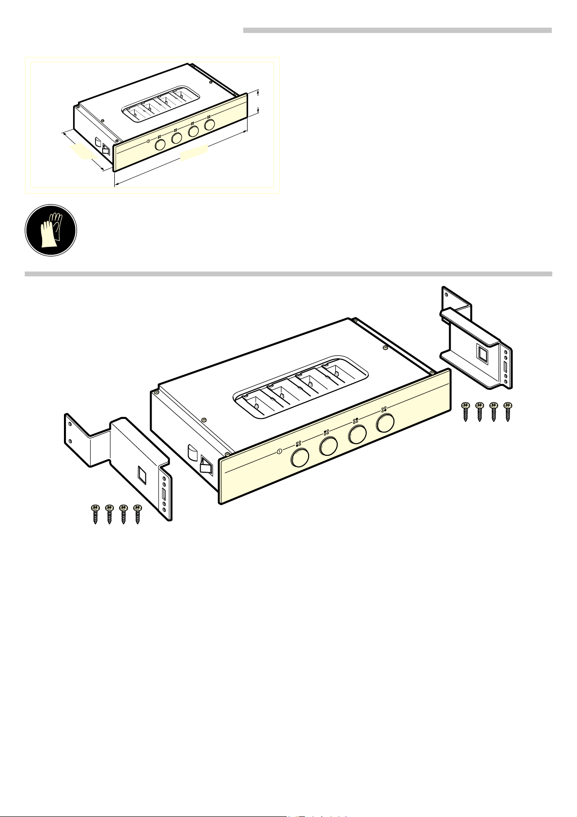
Gerät einbauen - Bild 1
Zuerst Einbauschaltkasten einbauen und anschließen, dann das
Kochfeld einbauen.
Ausschnitt in der Arbeitsplatte für Kochfeld muss vorhanden
sein.
Ausschnitt für Einbauschaltkasten mittig in die Möbelfront
schneiden.
Metallträger links und rechts bündig mit der Möbelfront anlegen.
Die Kerbe des Metallträgers muss 43 mm von der Unterkante
entfernt sein. Mit je vier Schrauben befestigen.
Einbauschaltkasten vorsichtig einschieben. Dabei Anschlusska-
bel nicht knicken, einklemmen oder über scharfe Kanten führen.
Gerät anschließen - Bild 2
Nur ein konzessionierter Fachmann darf das Gerät anschließen.
Die Absicherung muss gemäß der Leistungsangabe auf dem
Typenschild und den lokalen Vorschriften erfolgen.
Das Gerät entspricht der Schutzklasse I und darf nur mit Schutz-
leiteranschluss betrieben werden.
Netzanschlussleitung: Typ H05 V V-F oder höherwertig. Die
gelb-grüne Ader für den Schutzleiteranschluss muss gerätesei-
tig 10 mm länger sein als die anderen Adern.
In der Installation muss ein allpoliger Trennschalter mit mindes-
tens 3 mm-Kontaktöffnung vorhanden sein, oder das Gerät wird
über einen Stecker mit Schutzkontakt-System angeschlossen.
Dieser muss nach dem Einbau noch zugänglich sein.
Der Berührungsschutz muss durch den Einbau gewährleistet
sein. Der Einbauschaltkasten darf nur mit Hilfe von Werkzeugen
ausbaubar sein.
Phasen- und Neutral- (“Null-“) Leiter in der Anschlussdose iden-
tifizieren. Bei Falschanschluss kann das Gerät beschädigt wer-
den.
Nur nach Anschlussbild anschließen.
Kochfeld anschließen - Bild 2
Grün-gelbes Erdungskabel des Kochfeldes an die Erdungs-
schraube
< des Gerätes anschließen. Bei nicht angeschlosse-
nem Erdungskabel besteht Stromschlaggefahr!
Farbig gekennzeichnete Stecker in die gleichfarbig gekenn-
zeichneten Buchsen des Gerätes stecken.
Ausbau
1. Gerät spannungslos machen.
2. Kochfeld oder Zwischenboden abnehmen.
3. Einbauschaltkasten von hinten herausdrücken.
fr
Þ
Notice de montage
Recommandations importantes
Cet appareil est conçu pour une utilisation jusqu'à une altitude
maximale de 2 000 m.
La table de cuisson et l'armoire de commande encastrable
doivent être du même fabricant et être combinables. Veillez aux
points de combinaison, ils doivent être identiques. Respectez la
notice de montage de la table de cuisson.
Avant d'encastrer l'appareil, vérifier s'il présente des avaries.
Avant la mise en service, retirer le matériau d'emballage et les
films adhésifs du compartiment de cuisson et sur la porte.
L'appareil doit être mis hors tension pour tous les travaux de
montage.
Préparation du meuble
Uniquement une installation effectuée selon cette notice de
montage garantit une utilisation en toute sécurité. En cas de
dommages résultant d'une installation incorrecte, l'installateur
est responsable.
Les meubles d'encastrement doivent résister à une température
jusqu'à 90 °C, la façade des meubles voisins jusqu'à 70 °C.
N'installez pas l'appareil derrière une plaque décorative. Il existe
un risque de surchauffe.
Effectuer tous les travaux de découpe sur le meuble et sur le
plan de travail avant d'encastrer les appareils. Enlever les
copeaux ! Le fonctionnement des composants électriques peut
être compromis.
Attention lors de l'encastrement ! Des éléments accessibles
pendant le montage peuvent posséder des arêtes coupantes.
Porter des gants de protection pour éviter des coupures.
Les meubles non fixés doivent être fixés au mur au moyen d'une
équerre usuelle du commerce.
Arrimer solidement les meubles au plan de travail.
Montage de l'appareil - Illustration 1
Installez et raccordez d'abord l'armoire de commande
encastrable, puis installez la plaque de cuisson.
Une découpe doit exister dans le plan de travail de la table de
cuisson.
Créez une découpe pour l'armoire de commande encastrable
au milieu de la façade du meuble.
Encastrez les supports métalliques à gauche et à droite au ras
de la surface du meuble. L'encoche des supports métalliques
doit se trouver à une distance de 43 mm du bord inférieur.
Fixez-les supports métalliques à l'aide de 4 vis.
Insérez l'armoire de commande encastrable avec précaution,.
en veillant à ne pas plier ni coincer le câble d'alimentation et à
ne pas le faire passer au-dessus d'arêtes coupantes.
Raccordement de l'appareil - Illustration 2
Seul un spécialiste agréé est habilité à raccorder l'appareil.
La protection par fusible doit s'effectuer conformément à
l'indication de puissance sur la plaque signalétique et les
prescriptions locales.
L'appareil répond à la classe de protection I et doit uniquement
être utilisé avec le raccordement à la terre.
Câble de raccordement secteur : type H05 V V-F ou supérieur.
Le fil jaune-vert pour le raccordement au conducteur de
protection doit être 10 mm plus long, côté appareil, que les
autres fils.
L'installation doit comprendre un sectionneur tous pôles d'un
interstice d'ouverture de contact d'au moins 3 mm ou l'appareil
doit être raccordé par une fiche dotée d'un système de sécurité.
Celle-ci doit encore être accessible après l'encastrement.
L'encastrement doit garantir la protection contre les contacts
accidentels. L'armoire de commande encastrable est
uniquement démontable à l'aide d'outils.
Identifier le conducteur de phase et le conducteur neutre dans
la prise de raccordement. En cas de branchement erroné,
l'appareil peut subir des dommages.
Effectuez uniquement le raccordement conformément au
schéma de raccordement.

Raccordement de la plaque de cuisson -
Illustration 2
Visser le câble de mise à la terre (vert-jaune) de la table de
cuisson sur la vis de mise à la terre
< de l'appareil. En cas de
câble de mise à la terre non raccordé il y a risque de choc
électrique !
Connecter les connecteurs de couleur dans les prises de
couleur identique de l'appareil.
Dépose
1. Mettre l'appareil hors tension.
2. Retirer la table de cuisson ou le plancher.
3. Faire pression sur l'armoire de commande encastrable par
l'arrière.
nl
é
Installatievoorschrift
Belangrijke aanwijzingen
Dit apparaat is bestemd voor gebruik tot op hoogten van
maximaal 2.000 meter boven zeeniveau.
De kookplaat en de inbouwschakelkast dienen van dezelfde
fabrikant en combineerbaar te zijn. Let op de combinatiepunten.
Deze moeten gelijk zijn. Neem het installatievoorschrift van de
kookplaat in acht.
Apparaat voor de inbouw controleren op transportschade.
Verpakkingsmateriaal en plakfolie voor ingebruikname
verwijderen uit de binnenruimte en van de deur.
Bij alle montagewerkzaamheden dient het apparaat
spanningsloos te zijn.
Meubel voorbereiden
Alleen als de inbouw op deskundige wijze en conform dit
installatievoorschrift wordt uitgevoerd, is de veiligheid bij het
gebruik gegarandeerd. De monteur is aansprakelijk voor
schade als gevolg van een verkeerde inbouw.
Inbouwmeubels dienen bestand te zijn tegen een temperatuur
van maximaal 90 °C, aangrenzende voorzijden van meubels
tegen een temperatuur van maximaal 70 °C.
Het apparaat nooit achter een decorplaat inbouwen. Er bestaat
gevaar van oververhitting.
Alle uitsnijdingswerkzaamheden aan het meubel en het
werkblad uitvoeren voordat de apparaten worden ingebracht.
Spanen verwijderen! Deze kunnen invloed hebben op de
werking van elektrische componenten.
Voorzichtig bij het inbouwen! Delen die tijdens het inbouwen
toegankelijk zijn, kunnen scherpe randen hebben. Draag
werkhandschoenen ter voorkoming van snijwonden.
Niet bevestigde meubels met een gebruikelijke, in de handel
verkrijgbare haak aan de wand bevestigen.
Werkblad en meubel goed aan elkaar bevestigen.
Apparaat inbouwen - Afbeelding 1
Eerst de schakelkast inbouwen en aansluiten, vervolgens de
kookplaat monteren.
In het werkblad dient een opening voor de kookplaat
aangebracht te zijn.
Midden in het meubelfront een opening voor de schakelkast
aanbrengen.
Metalen houders links en rechts vlak tegen het meubelfront
plaatsen. De groef van de metalen drager dient een afstand van
43 mm tot de onderkant te hebben. Aan beide kanten met vier
schroeven bevestigen.
Schakelkast (inbouw) voorzichtig inschuiven. Zorg ervoor dat
het aansluitsnoer hierbij niet knikt, wordt ingeklemd of over
scherpe randen geleid.
Apparaat aansluiten - Afbeelding 2
Alleen een daartoe bevoegd vakman mag het apparaat
aansluiten.
De zekering dient in overeenstemming te zijn met de
vermogensopgave op het typeplaatje en de lokale voorschriften.
Het apparaat voldoet aan veiligheidsklasse I en mag alleen met
aard aansluiting worden gebruikt.
Hoofdleiding (netaansluiting: type H05 V V-F of hoogwaardiger.
De geel-groene ader voor randaarding moet bij het apparaat
10 mm langer zijn dan de andere aders.
In de installatie dient een scheidingsschakelaar met een
contactopening van minstens 3 mm voorhanden te zijn, of het
apparaat wordt via een stekker op de aardleiding aangesloten.
De stekker dient na de inbouw nog toegankelijk te zijn.
De bescherming tegen aanraking dient door de inbouw te zijn
gewaarborgd. De schakelkast mag alleen met behulp van
gereedschap kunnen worden gedemonteerd.
Fase- en neutraal ("nul") leider in het stopcontact identificeren.
Bij een verkeerde aansluiting kan het apparaat worden
beschadigd.
Alleen aansluiten volgens het aansluitschema.
Kookplaat aansluiten - Afbeelding 2
Groen-gele aardingskabel van de kookplaat op de
aardingsschroef
< van het apparaat aansluiten. Wanneer de
aardingskabel niet is aangesloten bestaat het risico van een
schok.
De met een kleur aangeduide stekker in de bussen van het
apparaat steken die van dezelfde kleur zijn voorzien.
Demontage
1. Maak het apparaat spanningsloos.
2. Kookplaat of tussenschot afnemen.
3. Schakelkast er van achteren uitdrukken.
en
Ú
Installation instructions
Important notes
This appliance is intended for use up to a maximum height of
2000 metres above sea level.
The hob and built-in switch box must be made by the same
manufacturer and be designed to work in combination. Pay
attention to the combination features; they must be the same.
Observe the installation instructions for the hob.
Before installation, check the appliance for transportation
damage.
Before starting up the appliance, remove any packaging
material and adhesive film from the cooking compartment and
the door.
The appliance must be disconnected from the power supply
during all installation work.
Preparing the kitchen units
Safe use of this appliance can only be guaranteed if it has been
installed professionally in accordance with these installation
instructions. The installer is liable for damages incurred as a
result of incorrect installation.
Units into which ovens are to be fitted must be heat-resistant up
to 90 °C and adjacent cabinets up to 70 °C.
Do not install the appliance behind a decorative panel. There is
a risk of overheating.
Carry out all cut-out work on the furniture unit and worktop
before fitting the appliances. Remove shavings. Otherwise, the
correct operation of electrical components may be adversely
affected.
Caution during installation. Parts that are accessible during
installation may have sharp edges. Wear protective gloves to
prevent injury from cuts.
Secure freestanding units to the wall using standard,
commercially available brackets.
Permanently fix furniture units to the worktop.
Installing the appliance - fig. 1
First fit and connect the built-in switch box, then install the hob.
There must be a cut-out in the worktop for the hob.
The cut-out for the built-in switch box is to be cut centrally in the
front of the kitchen unit.
Position the metal support flush with the front of the kitchen unit
on the left and right. The notch on the metal support must be 43
mm from the bottom edge. Secure using the four screws.
Carefully slide in the built-in switch box. Do not kink or trap the
power cable, or route it over sharp edges.
Connecting the appliance - fig. 2
Only a licensed professional may connect the appliance.
The fuse protection must correspond to the power rating
specified on the appliance's rating plate and to local regulations.
The appliance corresponds to safety class I and may only be
operated in conjunction with a safety earth terminal.
Power cord: Type H05 V V-F or a higher rating. The yellowgreen
wire for the safety earth terminal must be 10 mm longer on the
appliance side than the other wires.
In the installation, there must be an all-pin isolating switch with at
least 3 mm contact gap, or the appliance must be connected

using a plug with an earthing contact. This must remain
accessible after installation.
Contact protection must be ensured by the method of
installation. The built-in switch box must only be removable
using tools.
Identify the phase and neutral (zero) conductors in the power
socket. The appliance could be damaged if incorrectly
connected.
Only connect the hob according to the connection diagram.
Connecting the hob - fig. 2
Connect the hob's yellow and green earth cable to the
appliance's
< earthing screw. There is a risk of electric shock if
the earthing cable is not connected.
Insert plugs identified with a colour into the sockets on the
appliance that have the same colour.
Removal
1. Disconnect the appliance from the power supply.
2. Remove the hob or intermediate floor.
3. Press out the built-in switch box from behind.
it
â
Istruzioni per il montaggio
Avvertenze importanti
Questo apparecchio è progettato solo per l'utilizzo fino ad
un'altezza di massimo 2000 metri sul livello del mare.
Il piano di cottura e l'unità di comando devono essere
combinabili e dello stesso produttore. Fare attenzione ai punti di
combinazione che devono coincidere. Rispettare le istruzioni di
montaggio del piano di cottura.
Prima dell'installazione, controllare che l'apparecchio non
presenti danni dovuti al trasporto.
Rimuovere il materiale di imballaggio e la pellicola adesiva dal
vano cottura e dallo sportello prima della messa in funzione.
Durante tutte le operazioni di montaggio l'apparecchio deve
essere senza tensione.
Preparazione dei mobili
L'utilizzo sicuro viene garantito solo se il montaggio è stato
effettuato in modo corretto secondo le presenti istruzioni. In
caso di danni dovuti a un montaggio scorretto la responsabilità
ricade su chi ha montato l'apparecchio.
I mobili da incasso devono essere termostabili fino a una
temperatura pari a 90 °C e i mobili contigui fino a 70 °C.
Non montare l'apparecchio dietro a un pannello decorativo.
Sussiste il pericolo di surriscaldamento.
Completare tutti i lavori di taglio sui mobili e sul piano di lavoro
prima di inserire l'apparecchio. Rimuovere i trucioli in quanto
possono pregiudicare il funzionamento dei componenti elettrici.
Prestare attenzione durante il montaggio! Parti che restano
scoperte durante il montaggio possono essere appuntite.
Indossare guanti protettivi per evitare di procurarsi ferite da
taglio.
Fissare il mobile alla parete con un angolare disponibile in
commercio.
Fissare il mobile al piano di lavoro.
Montaggio dell'apparecchio - Figura 1
Dapprima incassare e collegare l'unità di comando, quindi
montare il piano di cottura.
Deve essere predisposta un'apertura nel piano di lavoro per
inserire il piano di cottura.
Tagliare il frontale del mobile al centro in modo da creare
un'apertura in cui inserire l'unità di comando.
Inserire il supporto in metallo a destra e sinistra in modo che sia
a filo con la parte frontale del mobile. La scanalatura del
supporto in metallo deve trovarsi a una distanza di 43 mm dal
bordo inferiore. Fissare con quattro viti per parte.
Inserire con cautela l'unità di comando. Fare in modo che il
cavo di allacciamento non si pieghi, non rimanga incastrato e
non passi su spigoli vivi.
Collegamento dell'apparecchio - Figura 2
L'allacciamento dell'apparecchio può essere effettuato solo da
un tecnico autorizzato.
La protezione avviene secondo la potenza indicata sulla
targhetta di identificazione e nel rispetto delle disposizioni locali.
L'apparecchio appartiene alla classe di protezione I ed è in
grado di funzionare solo se dotato di un conduttore di terra.
Cavo di collegamento alla rete elettrica: modello H05 V V-F o
superiore. Il filo giallo-verde per il collegamento del conduttore
di terra, dal lato dell'apparecchio, deve essere 10 mm più lungo
degli altri.
Nell'installazione deve essere presente un sezionatore
universale con un'apertura di contatto di almeno 3 mm. In caso
contrario l'apparecchio viene collegato tramite una presa con un
sistema di messa a terra che deve rimanere accessibile anche
dopo il montaggio.
La protezione da contatto deve essere garantita tramite il
montaggio. L'unità di comando può essere smontata solo con
l'ausilio di attrezzi.
Nell'elemento femmina, individuare un conduttore di fase e uno
neutro (“zero”). Un allacciamento scorretto dell'apparecchio può
comportarne il danneggiamento.
Attenersi sempre allo schema di allacciamento.
Collegamento del piano di cottura - Figura 2
Collegare il cavo di messa a terra giallo-verde del piano di
cottura al morsetto di terra
< dell'apparecchio. In caso di
conduttore di terra non allacciato vi è pericolo di scariche
elettriche!
Inserire la spina colorata nelle prese dell'apparecchio con lo
stesso colore.
Smontaggio
1. Scollegare l'apparecchio.
2. Estrarre il piano di cottura o il doppiofondo.
3. Spingere in fuori da dietro l'unità di comando.