SAFETY PILOT This heater has a pilot with an Oxygen Depletion Sensing (ODS) safety shutoff system. The ODS/pilot shuts off the heater if there is not enough fresh air and cuts off main burner gas in the event of flame out.
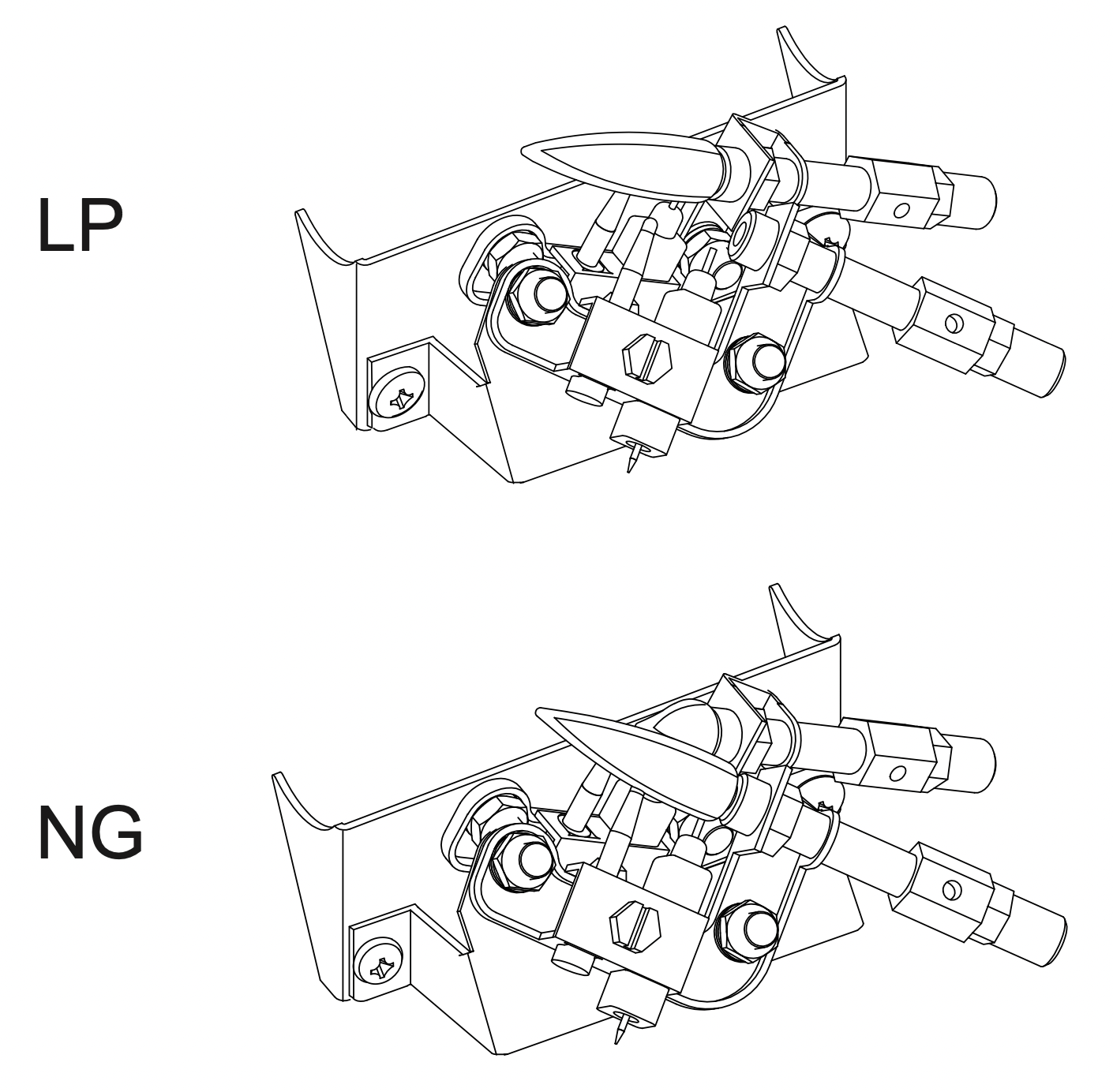
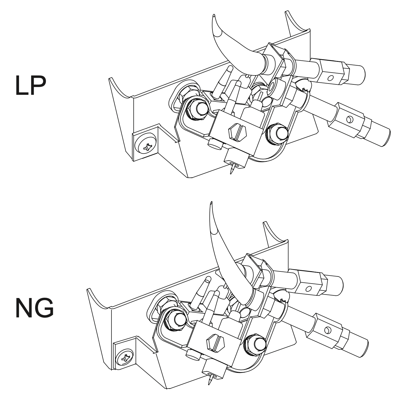
DUAL FUEL CAPABILITY Your heater is equipped to operate on either propane or natural gas. The heater is shipped from the factory ready for connecting to propane. The heater can easily be changed to natural gas by having your qualified installer follow the instructions on page 11 and the markings on the heater.
LEG KIT (SELECT MODELS) 2 support legs and 4 support leg screws are included for floor mounting the heater. See page 13. NOTE: This is an optional accessory and is not required for operation of the heater.
ELECTRONIC PUSH BUTTON IGNITION SYSTEM This heater is equipped with an electronic push button ignition system. This system requires one AAA battery (provided).
THERMOSTAT HEAT CONTROL (SELECT MODELS) The control automatically cycles the burner on and off to maintain a desired room temperature. See page 24.
FAN KIT (SELECT MODELS) The fan kit helps to distribute the warmed air into the space more rapidly.
NOTE: This is an optional accessory and is not required for operation of the heater.
State of Massachusetts: The installation must be made by a licensed plumber or gas fitter in the Commonwealth of Massachusetts. Sellers of unvented propane or natural gas-fired supplemental room heaters shall provide to each purchaser a copy of 527 CMR 30 upon sale of the unit.
In the State of Massachusetts, unvented propane or natural gas-fired space heaters shall be prohibited in bedrooms and bathrooms.
In the State of Massachusetts the gas cock must be a T-handle type. The State of Massachusetts requires that a flexible appliance connector cannot exceed three feet in length.
OPERATION
FOR YOUR SAFETY READ BEFORE LIGHTING
WARNING: If you do not follow these instructions exactly, a fire or explosion may result causing property damage, personal injury or loss of life.
A. This appliance has a pilot which must be lighted using the Ignitor. When lighting the pilot, follow these instructions exactly.
B. BEFORE LIGHTING smell all around the appliance area for gas. Be sure to smell next to the floor because some gas is heavier than air and will settle on the floor.
WHAT TO DO IF YOU SMELL GAS
Do not try to light any appliance.
Do not touch any electrical switch; do not use any phone in your building.
Immediately call your gas supplier from a neighbor’s phone. Follow the gas supplier’s instructions.
If you cannot reach your gas supplier, call the fire department.
C. Use only your hand to push in or turn the gas control knob. Never use tools. If the knob will not push in or turn by hand, don't try to repair it, call a qualified service technician. Forced or attempted repair may result in a fire or explosion.
D. Do not use this appliance if any part has been under water. Immediately call a qualified service technician to inspect the appliance and to replace any part of the control system and any gas control, which has been under water.
LIGHTING INSTRUCTIONS
MANUAL GAS CONTROL
STOP! Read the safety information above on this page.
Turn off all electric power to the appliance.
Push in gas control knob slightly and turn clockwise to OFF " " position. (See Fig. 22a) NOTE: Knob cannot be turned from PILOT " " to OFF " " unless knob is pushed in slightly. Do not force.
Wait (5) minutes to clear out any gas. Then smell for gas, including near the floor. If you smell gas, STOP! Follow “B” in the safety information above. If you don’t smell gas, go to the next step.
Push in gas control knob slightly and turn counter clockwise to the PILOT " " position. (See Fig. 23a) Depress control knob.
With control knob depressed, push down on the ignitor button until the pilot lights. The pilot is visible, centered below the main burner, behind the glass panel. (See Fig. 24 on page 19) Do not attempt to light the pilot by hand.
Keep control depressed for (30) seconds after pilot lights. Release control knob. Note: If pilot goes out repeat steps 3 through 7. Wait (1) minute before attempting to light pilot again. If after several tries the pilot still goes out, turn the gas control knob clockwise to the OFF " " position and call your service technician or gas supplier. If the control knob does not pop up when released, stop and immediately and call your service technician or gas supplier.
Turn on all electric power to the appliance.
Turn control knob counter clockwise to HIGH " " setting.
THERMOSTAT GAS CONTROL
STOP! Read the safety information on the previous page.
Turn off all electric power to the appliance.
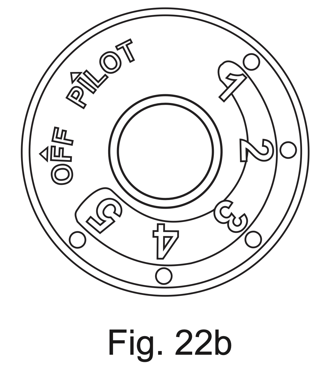
Turn control knob clockwise to "OFF" position. (See Fig. 22b)
Wait (5) minutes to clear out any gas. Then smell for gas, including near the floor. If you smell gas, STOP! Follow “B” in the safety information above. If you don’t smell gas, go to the next step.
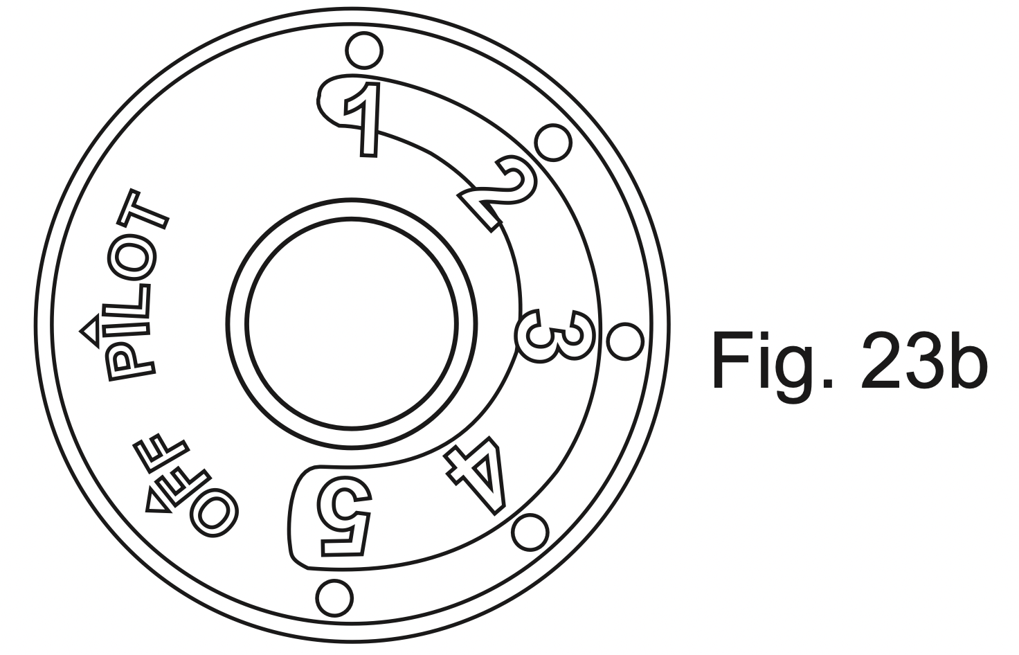
Turn knob counterclockwise to the "PILOT" position. (See Fig. 23b) Depress control knob.
With control knob depressed, push down on the ignitor button until the pilot lights. The pilot is visible, centered below the main burner, behind the glass panel. (See Fig. 24 on page 19) Do not attempt to light the pilot by hand.
Keep control depressed for (30) seconds after pilot lights. Release control knob. Note: If pilot goes out repeat steps 3 through 7. Wait (1) minute before attempting to light pilot again. If after several tries the pilot still goes out, turn the gas control knob clockwise to the "OFF" position and call your service technician or gas supplier. If the control knob does not pop up when released, stop and immediately and call your service technician or gas supplier.
Turn on all electric power to the appliance.
Turn control knob counter clockwise to desired setting.
TO TURN OFF GAS TO APPLIANCE
Turn off all electric power to the appliance if service is to be performed.
Push in gas control knob slightly and turn clockwise to "OFF" or " " position. DO NOT FORCE.
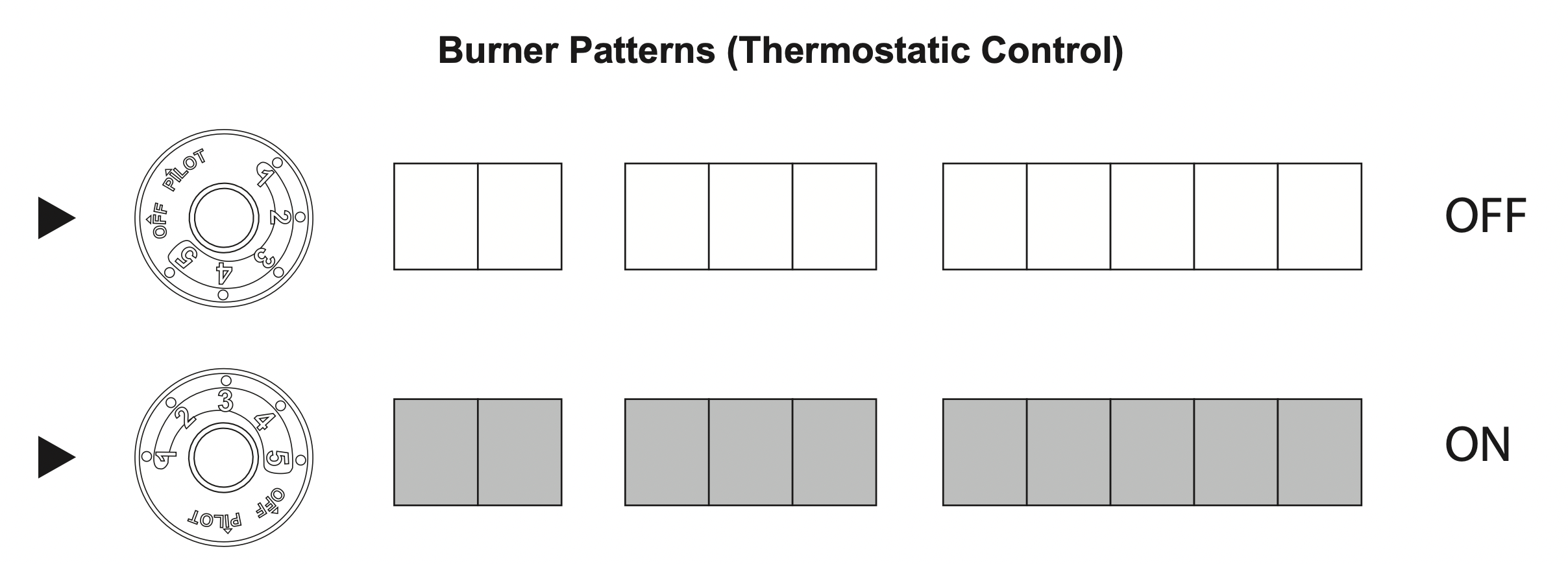
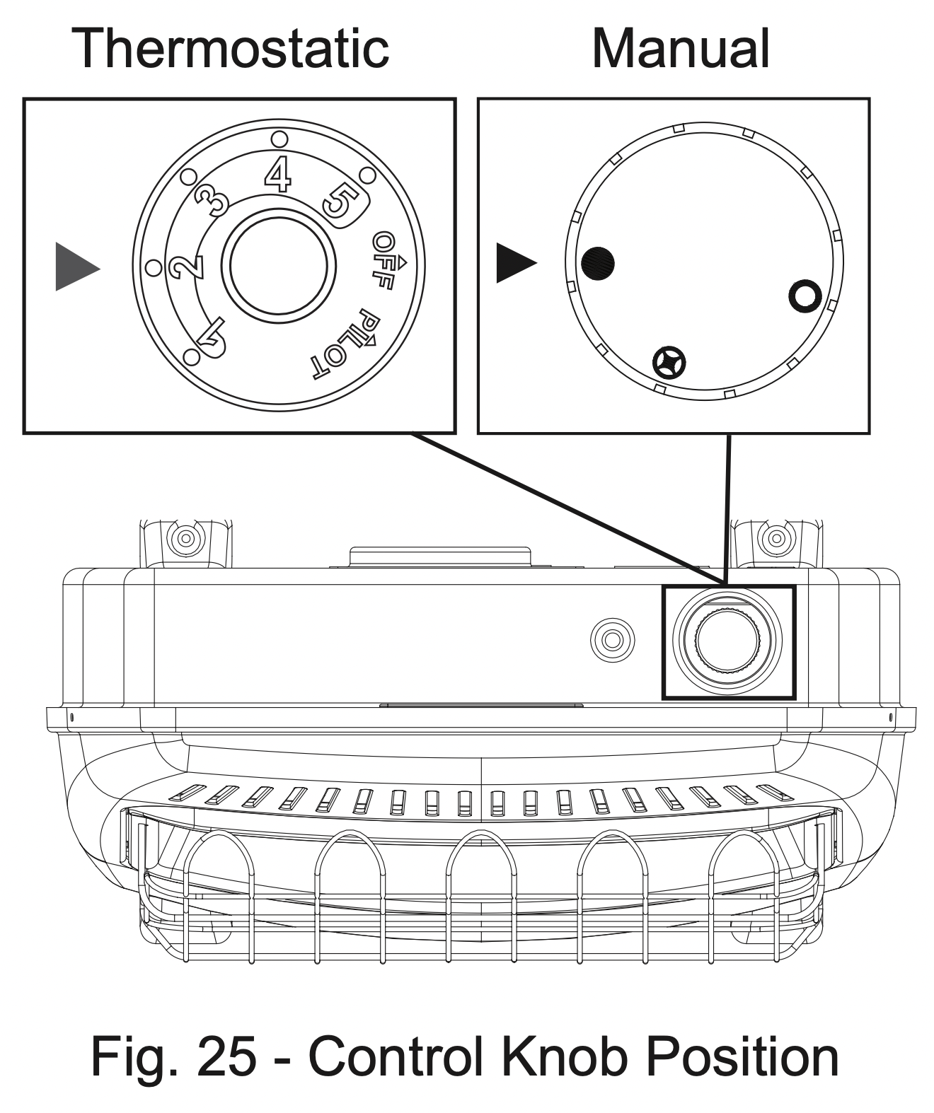
THERMOSTATIC CONTROL OPERATION (SELECT MODELS)
The thermostat used on this heater senses the room temperature. At times the room may exceed the set temperature. If so, the burner will shut off. The burner will cycle back on when room temperature drops below the set temperature. The control knob can be set to any comfort level between "HIGH" (5) and "LOW"(1) (See Fig. 25).
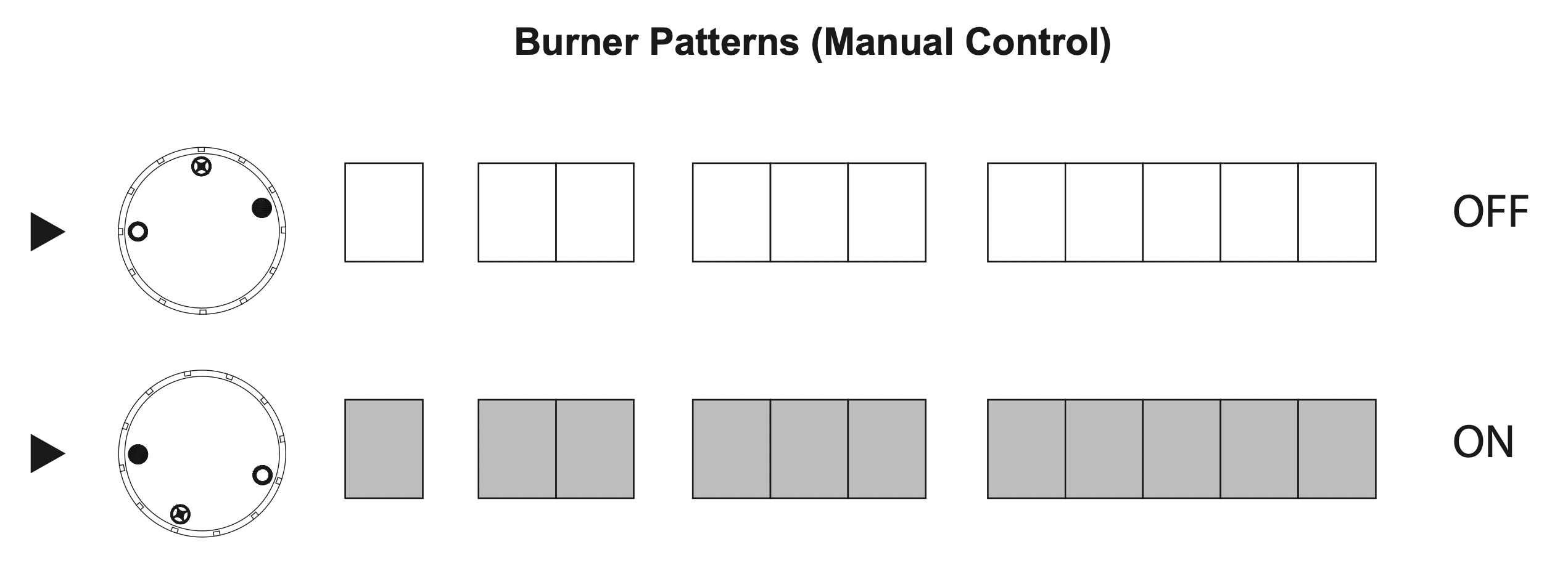
MANUAL CONTROL OPERATION
Manual valves remain burning in the HIGH " " setting until manually turned to OFF " "(See Fig. 25).
INSPECTING BURNERS
Check pilot flame pattern daily when in use and at least yearly by a qualified service agency.
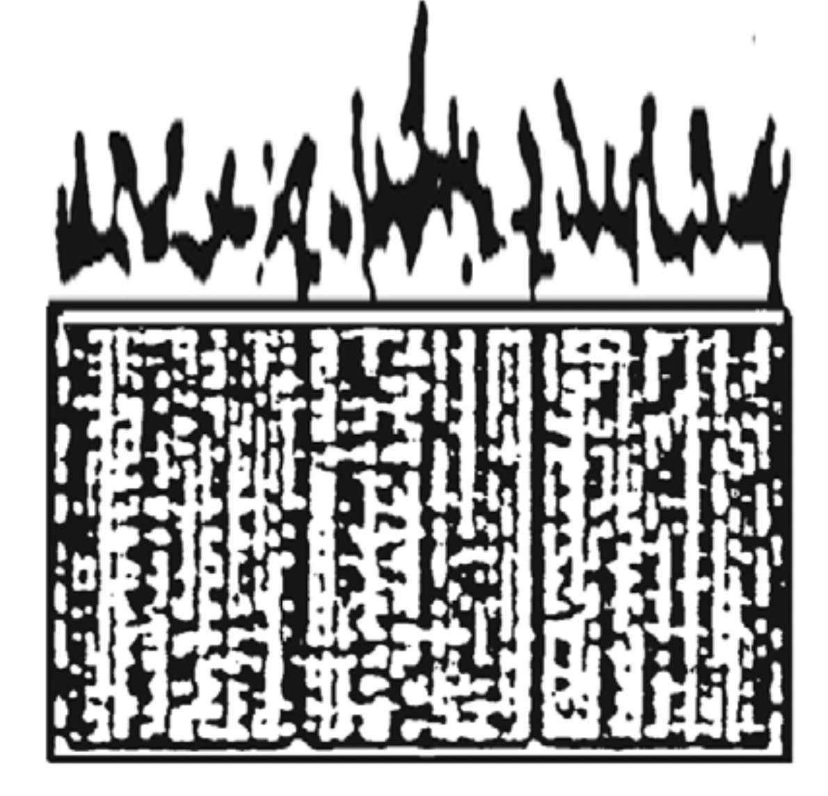
PILOT FLAME PATTERN
Fig. 26 shows a correct pilot flame pattern. Fig. 27 shows an incorrect pilot flame pattern. The incorrect pilot flame is not touching the thermocouple. This will cause the thermocouple to cool, which shuts the heater off. If pilot flame pattern is incorrect:
turn heater off (see “To Turn Off Gas to Appliance” on page 19)
see Troubleshooting pages 23 through 26.
Fig. 26 - Correct Pilot Flame Pattern
Fig. 27 - Incorrect Pilot Flame Pattern
WARNING: If yellow tipping occurs, your heater could produce increased levels of carbon monoxide. If burner flame pattern shows yellow tipping, follow instructions under BURNER FLAME PATTERN, page 21.
Notice: Do not mistake orange flames with yellow tipping. Dirt or other fine particles enter the heater and burn causing brief patches of orange flame.
BURNER FLAME PATTERN
Fig. 28 shows a correct burner flame pattern. Fig. 29 shows an incorrect burner flame pattern with lifting, and excessive flame height.
If burner flame is incorrect:
turn heater off (see “To Turn Off Gas to Appliance”, page 19).
see Troubleshooting, pages 23 through 26.
Fig. 28 - Correct/Normal Flame Pattern with short flames with Control Knob Set to High Flame (5)
Fig. 29 - Incorrect/Abnormal Flame Pattern with tall flames with Control Knob Set to High Flame (5)
CARE AND MAINTENANCE
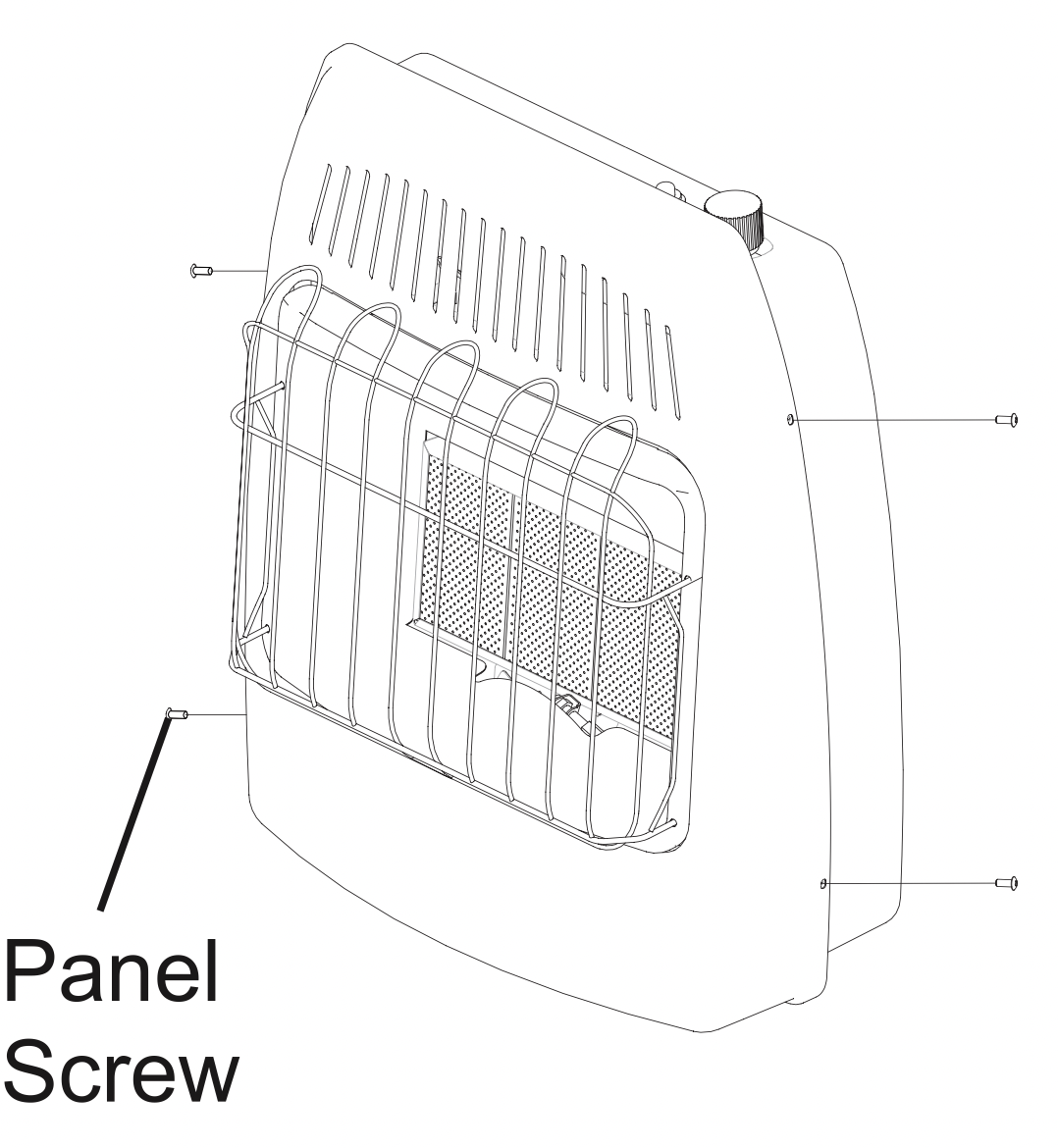
NOTE: Before servicing you will need to remove the front panel of the heater. There are 4 Philips head screws, 2 on the left side and 2 on the right, securing the front panel to the heater (See Fig. 30). Always allow the unit to cool for at least thirty minutes before attempting to remove the front panel.
Fig. 30 - Front Panel Removal
WARNING: Turn off heater, unplug electrical cord and let cool before servicing.
CAUTION: You must keep control areas, burner, and circulating air passageways of heater clean. Inspect these areas of heater before each use. Have heater inspected yearly by a qualified service person. Heater may need more frequent cleaning due to excessive lint from carpeting, bedding material, pet hair, etc.
WARNING: Failure to keep the primary air opening(s) of the burner(s) clean may result in sooting and propery damage.
CLEANING ODS/PILOT AND BURNER Use a vacuum cleaner, pressurized air, or a small, soft bristled brush to clean tile face, orifice and primary burner. Look into burner opening and ensure that it is clean.
CLEANING BURNER PILOT AIR INLET HOLE We recommend that you clean the unit every three months or after 2,500 hours of operation. We also recommend that you keep the burner tube and pilot assembly clean and free of dust and dirt. To clean these parts we recommend using compressed air no greater than 30 PSI. You can use a vacuum cleaner in the blow position. If using compressed air in a can, please follow the directions on the can. If you don't follow directions on the can, you could damage the pilot assembly.
CAUTION: Never use a wire, needle, or similar object to clean ODS/pilot. This can damage ODS/ pilot unit.
Shut off the unit, including the pilot. Allow the unit to cool for at least thirty minutes.
Remove 4 screws - 2 screws on each side of the front panel.
Pull front panel forward.
Blow air through the ports/slots and holes in the burner. Also clean the pilot assembly. A yellow tip on the pilot flame indicates dust and dirt in the pilot assembly. There is a small pilot air inlet hole about two inches from where the pilot flame comes out of the pilot assembly (see Fig. 26 & 27 on page 20). With the unit off, lightly blow air through the air inlet hole. You may blow through a drinking straw if air is not available.
Replace front panel when completed, using the screws removed.
CLEANING CABINET AIR PASSAGEWAYS Use a vacuum cleaner or pressurized air to clean.
CLEANING FAN (Select models) Carefully use a vacuum cleaner or compressed air to keep fan compartment and blades free of dust and debris.
NOTE: The fan motor is pre-lubricated for extended bearing life and requires no further lubrication.
CLEANING EXTERIOR Use a soft cloth dampened with a mild soap and water mixture. Wipe the cabinet to remove dust.
TROUBLESHOOTING
WARNING: If you smell gas:
Shut off gas supply.
Do not try to light any appliance.
Do not touch any electrical switch; do not use any phone in your building.
Immediately call your gas supplier from a neighbor’s phone. Follow the gas supplier’s instructions.
If you cannot reach your gas supplier, call the fire department.
IMPORTANT: Operating heater where impurities in air exist may create odors. Cleaning supplies, paint, paint remover, cigarette smoke, cements and glues, new carpet or textiles, etc., create fumes. These fumes may mix with combustion air and create odors.
WARNING: Make sure that power is turned off before proceeding.
WARNING: Turn off and let cool before servicing. Only a qualified service person should service and repair heater.
PROBLEM
POSSIBLE CAUSE
CORRECTIVE ACTION
When Ignitor Module is pressed in, there is no spark at ODS/pilot.
Ignitor electrode is positioned wrong.
Ignitor electrode is broken.
Ignitor electrode is not connected to ignitor cable.
Ignitor cable is pinched or wet.
Damaged ignitor cable.
Bad ignitor module or ignition module.
Bad battery.
Replace ODS.
Replace ODS.
Replace ignitor cable
Free ignitor cable if pinched by any metal or tubing. Keep ignitor cable dry.
Replace ignitor cable.
Replace ignitor module or ignition module.
Replace bad battery.
Unit shuts off after running a few minutes.
Gas supply is turned off or equipment shutoff valve is closed.
Control knob not fullypressed in while pressing PiezoIgnitor.
Air in gas lines when installed.
ODS / pilot is clogged.
Gas regulator setting is not correct.
Control knob not in PILOT position.
Depleted gas supply (propane).
Incorrect gas setting regulator or selector valve.
Turn on gas supply or open equipment shutoff valve.
Fully press in control knob while pressing Ignitor Module.
Continue holding down control knob. Repeat igniting operation until air is removed.
Clean ODS/pilot (see Care and Maintenance, page 21) or replace ODS/pilot assembly.
Replace gas regulator.
Turn control knob to PILOT position.
Contact local propane/LP gas company.
Call qualified service technician.
ODS/pilot lights but flame goes out when control knob is released.
Control knob is not fully pressed in.
Control knob is not pressed in long enough.
Equipment shutoff valve is not fully open.
Thermocouple connection is loose.
Thermocouple damaged.
Control valve damaged.
Wrong Gas Setting
Press in control knob fully.
After ODS/pilot lights, keep control knob pressed in 30-60 seconds.
Fully open equipment shutoff valve.
Hand tighten until snug, and then tighten ¼ turn more.
Replace thermocouple.
Contact customer service.
Correct Gas Selection - Contact your gas supplier
Burner(s) does not light afterODS/pilot is lit.
Thermostat setting too low.
Burner orifice is clogged.
Burner orifice diameter is too small.
Inlet gas pressure is too low.
Turn thermostat knob to a higher setting.
Clean burner orifice (see Care and Maintenance, page 21) or contact customer service.
Contact customer service.
Contact your gas supplier.
Delayed ignition of burner(s).
Manifold pressure is too low.
Burner orifice is clogged.
Contact your gas supplier.
Clean burner (see Care and Maintenance, page 21) or contact customer service.
Burner back firing during combustion.
Burner orifice is clogged or damaged.
Burner is damaged.
Gas regulator is damaged.
Clean burner orifice (see Care and Maintenance, page 21 or contact customer service.
Contact dealer or customer service.
Replace gas regulator.
High yellow flame during burner combustion
Not enough air.
Gas regulator is defective.
Wrong gas type selected.
Check burner for dirt and debris. If found, clean burner (see Care and Maintenance, page 21).
Replace gas regulator.
See Gas Selection, page 11.
Gas odor during combustion.
Foreign matter between control valve and burner.
Gas leak. (See Warning Statement at top of page 23).
Take apart gas tubing and remove foreign matter.
Locate and correct all leaks (see “Checking Gas Connections,” page 17).
Heater produces a clicking/ticking noise just after burner is lit or shutoff.
Metal is expanding while heating or contracting while cooling.
This is common with most heaters. If noise is excessive, contact qualified service technician.
White powder residue forming within burner box or on adjacent walls or furniture.
When heated, the vapors from furniture polish, wax, carpet cleaners, etc., turn into white powder residue.
Turn heater off when using furniture polish, wax, carpet cleaner or similar products.
Heater produces unwanted odors.
Heater is burning vapors from paint, hair spray, glues, etc. See IMPORTANT statement, page 22.
Gas leak. See Warning Statement, page 23.
Low fuel supply.
Ventilate room. Stop using odor causing products while heater is running.
Locate and correct all leaks (see “Checking Gas Connections”, page 17).
Refill supply tank (Propane /LP models).
Heater shuts off in use (OD Soperates).
Gas odor exists even when control knob is in OFF position.
Not enough fresh air is available.
Low line pressure.
ODS/pilot is partially clogged.
Open window and/or door for ventilation.
Contact local gas supplier.
Clean ODS/pilot (see Care and Maintenance, page 22).
Gas leak. See Warning Statement at top of page 22.
Control valve is defective.
Locate and correct all leaks (see “Checking Gas Connections”, page 17).
Contact customer service.
Moisture/ condensation noticed on windows.
Not enough combustion/ ventilation air.
Refer to “Air for Combustion and Ventilation” requirements, page 7.
Slight smoke or odor during initial operation
Residues from manufacturing process.
Problem will stop after a few hours of operation.
Heater produces a whistling noise when burner is lit.
Turning control knob to high (5) position when burner is cold.
Air in gas line.
Air passage ways on heater are blocked.
Dirty or partially clogged burner orifice.
Turn control knob to low (1) positionand let warm up for a minute.
Operate burner until air is removed from line. Have gas line checked by local propane/LP gas company.
Clean burner (see Care and Maintenance, page 22) or contact customer service.
Fan is not spinning. (Select models)
There is no power to the fan.
Fan is set to "AUTO".
Fan motor is bad.
Verify fan is plugged in and set to "MAN" or "AUTO".
Allow 5-10 minutes for fan to engage.
Replace fan.
Fan is making a loud noise. (Select models)
Fan housing or blades are dirty.
Fan rotation is blocked.
Defective fan.
See "Cleaning Fan", page 22.
Verify wiring is not in fan path.
Replace fan.
QUALIFIED INSTALLING AGENCY Only a qualified agency should perform installation and replacement of gas piping, gas utilization equipment or accessories, and repair and servicing of equipment. The term “qualified agency” means any individual, firm, corporation, or company that either in person or through a representative is engaged in and is responsible for:
a) Installing, testing, or replacing gas piping or
b) Connecting, installing, testing, repairing, or servicing equipment; that is experienced in such work; that is familiar with all precautions required; and that has complied with all the requirements of the authority having jurisdiction.
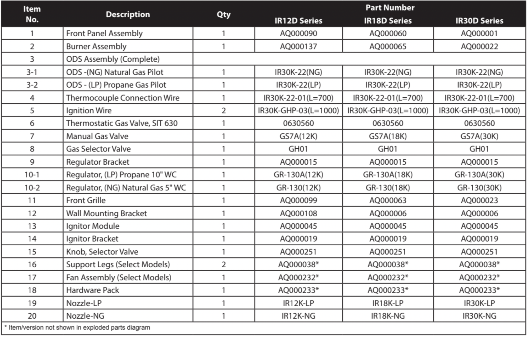
REPLACEMENT PARTS LIST
For replacement parts, call our customer service department at 1-877-447-4768, 8:30 a.m. – 4:30 p.m., CST, Monday – Friday.
WARNING: Only use genuine replacement parts from the GHP Group, Inc. Using any parts other than the original replacement parts may result in property damage, personal injury or even death.
 to OFF "
  " position. (See Fig. 22a)
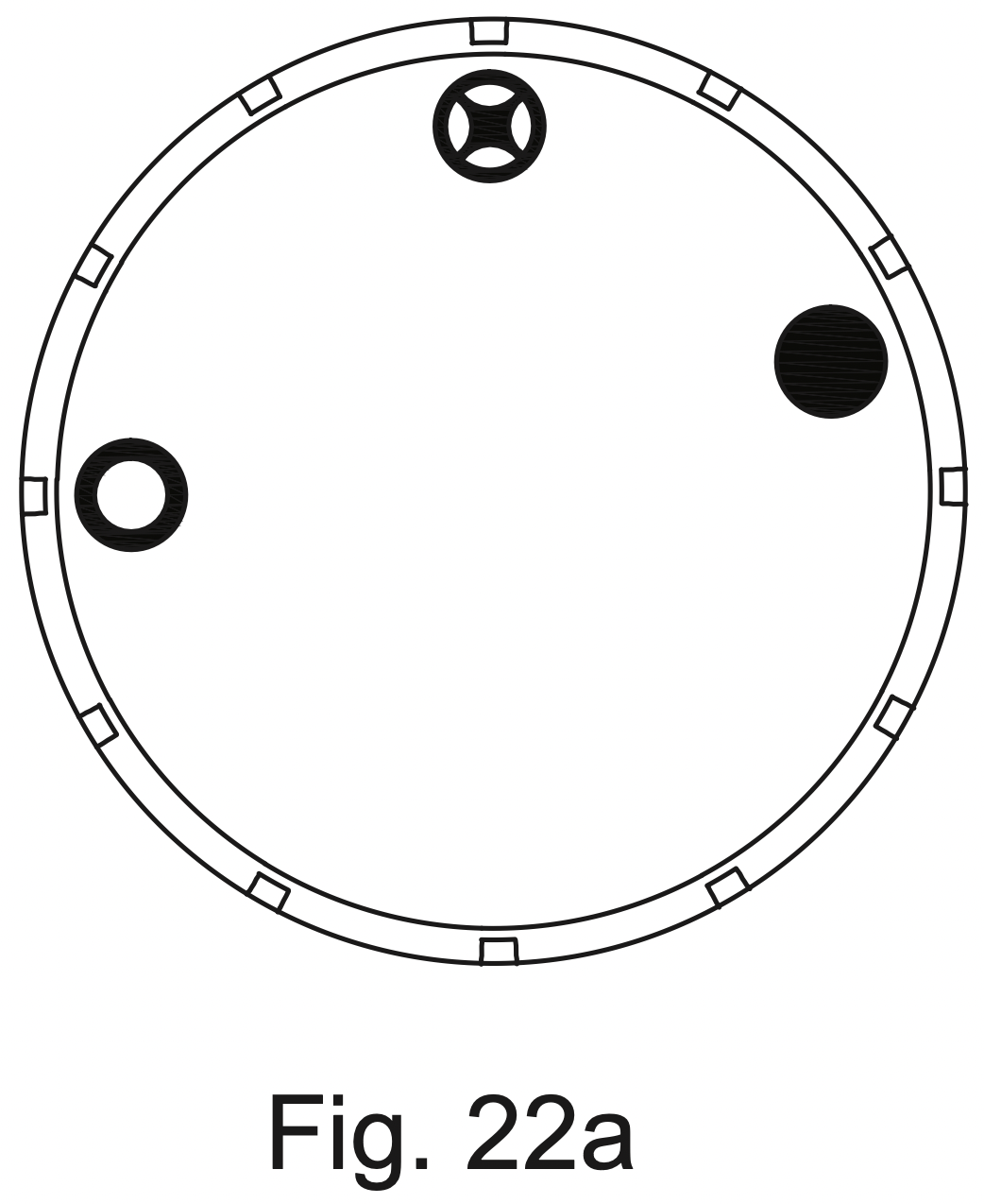
 " to OFF "
  " unless knob is pushed in slightly. Do not force.
 to the PILOT "
  " position. (See Fig. 23a) Depress control knob.
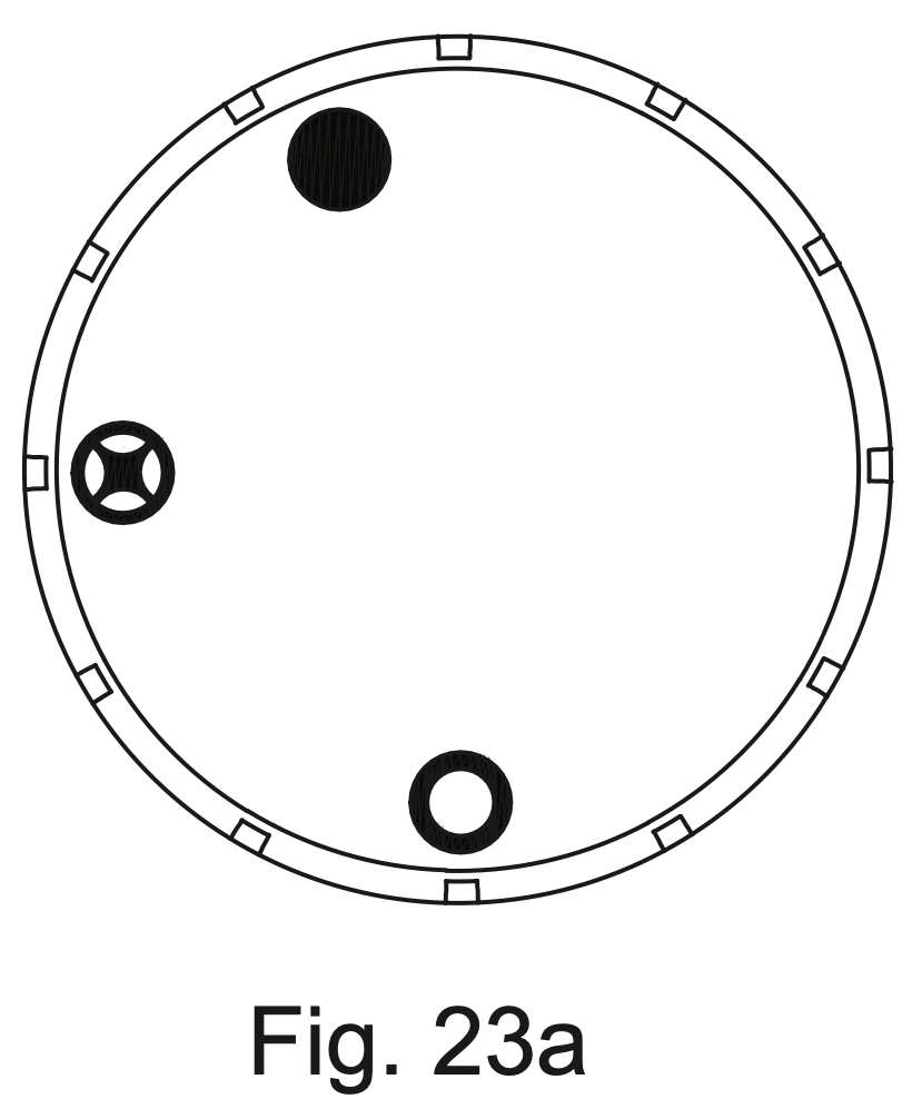
 to the OFF "
  " position and call your service technician or gas supplier.
 to HIGH "
  " setting.