Loading ...
Loading ...
Loading ...
Piping
Liebert
®
SRC
™
User Manual 42
5.2.5 Obstacles
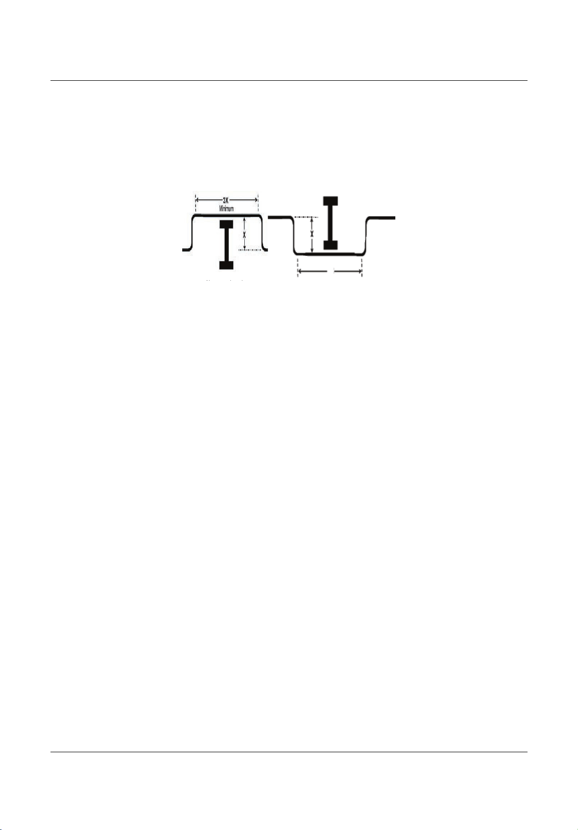
When an obstacle, such as an I-beam or concrete T, is in the path of the planned refrigerant-pipe run, it is
best practice to route the pipe over the obstacle. If adequate space is not available to route the insulated
pipe
over the obstacle, then route the pipe under the obstacle. In either case, it is imperative that the length
of the horizontal section of pipe above or below the obstacle be a minimum of 3-times the longest vertical
rise (or
fall) at either end of the segment, Figure5-6.
Figure 5-6 Installing p iping above and below an obstacle
5.2.6 Copper Expansion and Contraction
Under normal operating conditions, the vapor pipe temperature of a Liebert SRC can vary as much as
280°F. With this large variance in pipe temperature, the designer must consider pipe expansion and
contraction to avoid pipe and fitting fatigue failures.
Refrigerant pipe along with
the insulation jacket form a cohesive unit that expands and contracts together.
During system operation, thermal heat transfer occurs between the pipe and the surrounding insulation.
If the pipe is mounted in free-air space, no natural restriction to movement is present,
if the mounting clips
are properly spaced and installed. When the refrigerant pipe is mounted underground in a utility duct,
stacked among other pipes, natural restriction to linear movement is present. In extreme cased, the
restrictive force of surface friction between insulation
jackets could become so great that natural expansion
ceases and the pipe is “fixed” in place. In this situation, opposing force caused by change in refrigerant
fluid/vapor temperature can lead to stress failure of pipes/fittings.
The refrigerant-pipe support system must be
engineered to allow free expansion to occur. When a
segment of pipe is mounted between two fixed points, provisions must be provided to allow pipe expansion
to naturally occur. The most common method is the inclusion of expansion loops or U-bends. Each
segment of
pipe has a natural fixed point where no movement occurs. This fixed point is located at the
center point of the segment assuming that the entire pipe is insulated in a similar fashion. The natural fixed
point of the pipe segment is typically where the
expansion loop or U-bend should be.
Linear pipe expansion can be calculated using the following formula:
LE = C x L x (T
r
– T
a
) x 12
LE = Anticipated linear tubing expansion (in.)
C = Constant (for copper = 9.2 x 10
-6
in./in.°F)
L = Length of pipe (ft)
T
r
= Refrigerant-pipe temperature (°F)
T
a
= Ambient air temperature (°F)
12 = Inches-to-feet conversion (12 in./ft)
1.From Table 5-7, find the row corresponding with the actual length of the straight pipe segment.
2.Estimate the minimum and maximum temperature of the pipe.
In the column showing the minimum pipe temperature, look up
the anticipated expansion distance. Do
the same for the maximum pipe temperature.
Ab b l
3X
Above an obstacle.
Below an obstacle.
MFL67502030 17. 7. 13. 오오 3:05 Page 52
Loading ...
Loading ...
Loading ...