
Loading ...
Loading ...
Loading ...
43
RS232C Port Specifications
Appendix
PC control of the TV
‡
Commands not indicated here are not guaranteed to operate.•
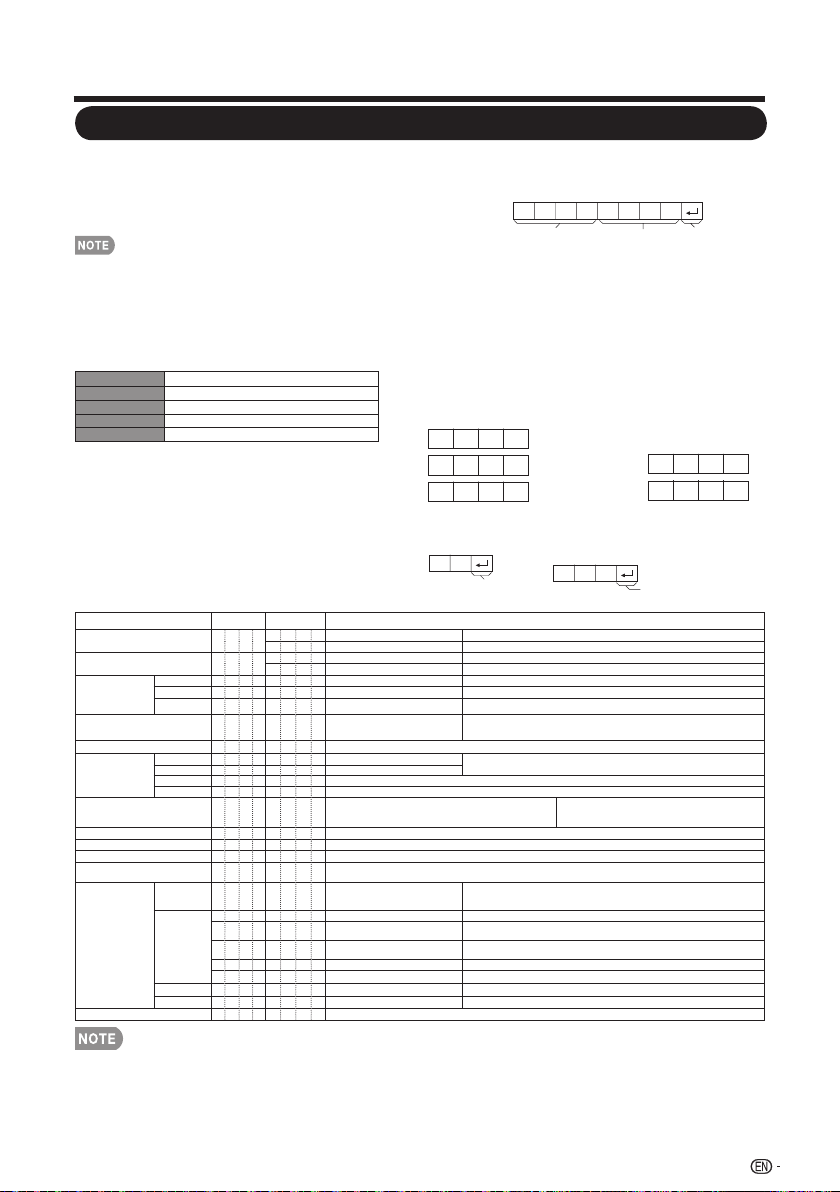
CONTROL ITEM COMMAND PARAMETER CONTROL CONTENTS
POWER ON COMMAND SETTING R S P W
0 _ _ _ Off The Power On command rejected. Not work in standby mode.
1 _ _ _ On The Power On command accepted.
POWER SETTING P O W R
0 _ _ _ Power Off It shifts to standby.
1 _ _ _ Power On Power On
INPUT
SELECTION A
TOGGLE I T G D _ _ _ _ (Toggle)
It input-switches by the toggle. (It is the same as an input change key)
TV I T V D _ _ _ _ It input-switches to TV. (A channel remains as it is. (Last memory)
Input terminal
number
I A V D * _ _ _
Input terminal number (1– input
number of device)
It input-switches to INPUT 1~5 (19”/ 22”) or INPUT 1~8 (32”).
AV MODE SELECTION
A V M D * _ _ _
0: (Toggle), 1: User, 2: Sports, 3:
Standard, 4: Movie. 5: Power saver
Although it can choose now, it is toggle operation in inside.
VOLUME V O L M * * * _ Volume (0–100)
POSITION
H-POSITION H P O S * * * _ H-POSITION (0 - 100) (PC)
The screen position variable ranges depend on the View Mode or the signal type. The
ranges can be seen on the position-setting screen.
V-POSITION V P O S * * * _ V-POSITION (0 - 100) (PC)
CLOCK C L C K * * * _ CLOCK (0–255) (PC)
PHASE P H S E * * _ _ PHASE (0–31) (PC)
VIEW MODE W I D E * _ _ _
0: (Toggle) [AV], 1: Automatic [AV], 2: Stretch [AV], 3: Side bar [AV], 4:
Smart stretch [AV], 5: Zoom [AV], 6: Dot by Dot [AV], 7: Stretch [PC],
8: Dot by Dot [PC].
0: Although it can choose now, it is toggle operation
in inside.
MUTE M U T E * _ _ _ 0: (Toggle), 1: On, 2: Off
SURROUND A C S U * _ _ _ 0: (Toggle), 1: On, 2: Off
AUDIO SELECTION A C H A _ _ _ _ (Toggle)
SLEEP TIMER O F T M * _ _ _
0: Off, 1: OFF TIMER – 10 MIN., 2: OFF TIMER – 20 MIN., 3: OFF TIMER – 30 MIN., 4: OFF TIMER – 40 MIN.,
5: OFF TIMER – 50 MIN., 6: OFF TIMER – 60 MIN., 7: OFF TIMER – 90 MIN., 8: OFF TIMER – 120 MIN.
CHANNEL
DIRECT
CHANNEL
(ANALOG)
D C C H * * _ _ The channel number of TV (1–135)
An input change is included if it is not TV display. In Air, 2–69ch is effective. In Cable,
1–135ch is effective.
DIRECT
CHANNEL
(DIGITAL)
D A 2 P * * * * (0100–9999) DIGITAL Air (Two-Part numbers, 2-digit plus 2-digit)
D C 2 U * * * _ (1-999)
DIGITAL Cable (Two-Part numbers, 3-digit plus 3-digit). Front half of DIGITAL CABLE
CHANNEL NO. (Designate major channel).
D C 2 L * * * _ (0-999)
DIGITAL Cable (Two-Part numbers, 3-digit plus 3-digit). Rear half of DIGITAL CABLE
CHANNEL NO. (Designate major channel).
D C 1 0 * * * * (0 - 9999) DIGITAL Cable (One-Part numbers, 5-digit, less than 10,000)
D C 1 1 * * * * (0 - 6383) DIGITAL Cable (One-Part numbers, 5-digit, more than 10,000)
CH UP C H U P _ _ _ _ CHANNEL UP
If it is not TV display, it will input-switch to TV. (same function as CH
r
)
CH DOWN C H D W _ _ _ _ CHANNEL DOWN
If it is not TV display, it will input-switch to TV. (same function as CH
s
)
CC C L C P _ _ _ _ (Toggle)
If an underbar (_) appears in the parameter column, enter a space.•
If an asterisk (*) appears, enter a value in the range indicated in brackets under CONTROL CONTENTS.•
Any numerical value can replace the “x” on the table.•
PC control of the TV
‡
The TV can be controlled from a PC using the RS-•
232C terminal.
Use a cross-type RS-232C cable (commercially •
available) for the connections.
This operation system should be used by a person who is •
accustomed to using computers.
Communication conditions
‡
Set the RS-232C communication settings on the PC
to match the TV’s communication conditions. The TV’s
communication settings are as follows:
Baud rate: 9,600 bps
Data length: 8 bits
Parity bit: None
Stop bit: 1 bit
Flow control: None
Communication procedure
‡
Send the control commands from the PC via the RS-
232C connector.
The TV operates according to the received command
and sends a response message to the PC.
Do not send multiple commands at the same time.
Wait until the PC receives the OK response before
sending the next command.
Command format
‡
Eight ASCII codes + CR
Command 4-digits
Parameter 4-digits
Return code
C1 C2 C3 C4 P1 P2 P3 P4
Command 4-digits: Command. The text of four
characters.
Parameter 4-digits: Parameter 0–9, x, blank, ?
Parameter
‡
Input the parameter values, aligning left, and fi ll with
blank(s) for the remainder. (Be sure that 4 values are
input for the parameter.)
When the input parameter is not within an adjustable
range, “ERR” returns. (Refer to “Response code
format”.)
Any numerical value can replace the “x” on the table.
0
0 0 0 9
- 3 0
When “?” is input for some
commands, the
present setting
value responds.
?
? ? ? ?
Response code format
‡
Normal response
Return code (0DH)
Return code (0DH)
Problem response (communication
error or incorrect command)
O K
E R R
Loading ...
Loading ...
Loading ...