Loading ...
Loading ...
Loading ...
15
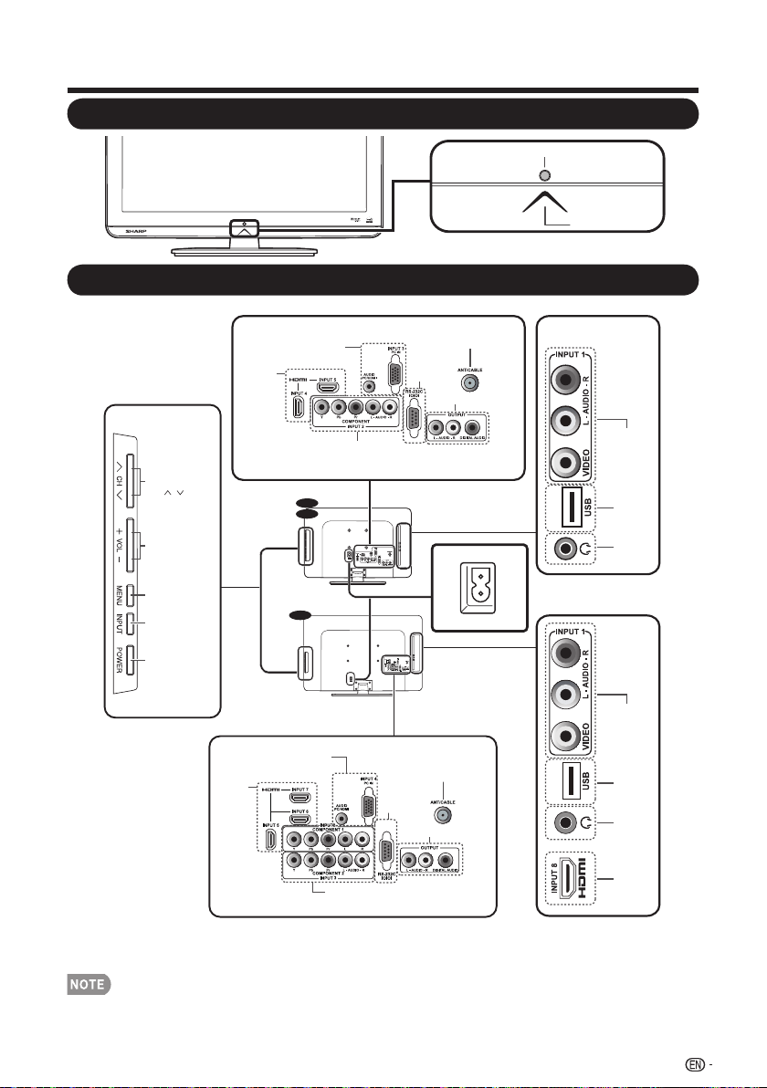
Remote control sensor
POWER indicator
(See page 19.)
Part Names
TV (Front)
TV (Side/Rear)
*1
*2
INPUT 1
(AV IN)
USB
Earphone
Output
INPUT 1
(AV IN)
USB
INPUT 8
(HDMI)
Earphone
Output
AC IN
Power conntector
22”
19”
32”
INPUT 4, 5
(HDMI)
Antenna/Cable in
RS-232C
IOIOI
INPUT 2
(COMPONENT)
AUDIO OUT
INPUT 3
(PC IN)
INPUT 5, 6, 7
(HDMI)
Antenna/Cable in
RS-232C
IOIOI
INPUT 2, 3
(COMPONENT)
AUDIO OUT
INPUT 4
(PC IN)
Volume buttons
(VOL +/- )
MENU button
INPUT button
POWER button
Channel buttons
(CH / )
*1: See pages 12, 17, and 18 for external equipment connection.
*2: See page 19 and 28 for button operations.
*3: See page 10 for connecting the AC cord.
The illustrations in this operation manual are for explanation purposes and may vary slightly from •
the actual operations.
The examples used throughout this manual are based on the LC-22LS510UT model.•
*3
Loading ...
Loading ...
Loading ...