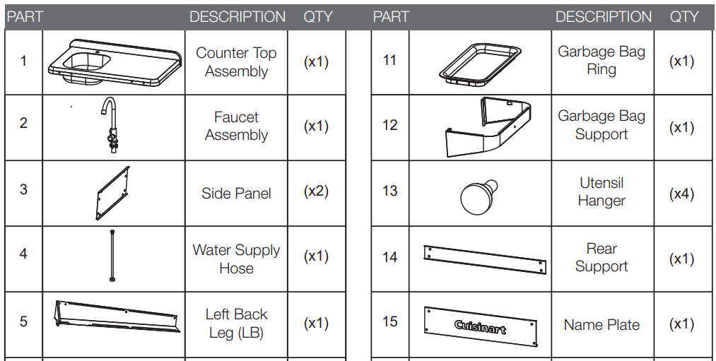
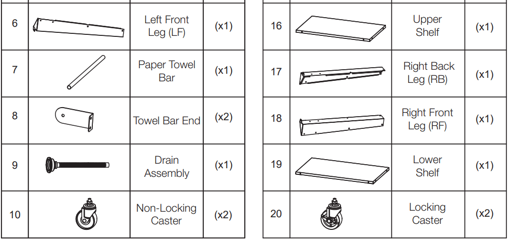
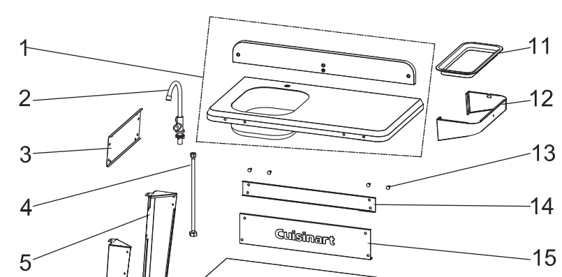
Please be careful when handling components. Always wear work gloves during assembly and set up. Read and follow all safety statements, warnings, assembly instructions and use and care instructions before attempting to assemble and use. Before beginning assembly of product, make sure all parts are present. Compare parts with package contents list and hardware contents list. If any part is missing or damaged, DO NOT attempt to assemble the product.
Estimated Assembly Time: 1 hour
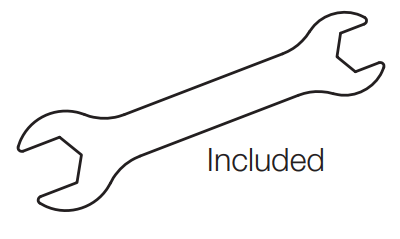
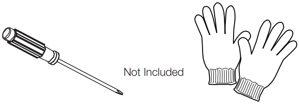
Tools required for assembly: (included) Wrench, (not included) Phillips Head Screwdriver (magnetic tip will be helpful), Gloves
ASSEMBLY INSTRUCTIONS
Assembly Tip: To avoid scratching prep table and to protect floor/patio surfaces, reuse cardboard packaging and lay parts on top while assembling.
STEP 1
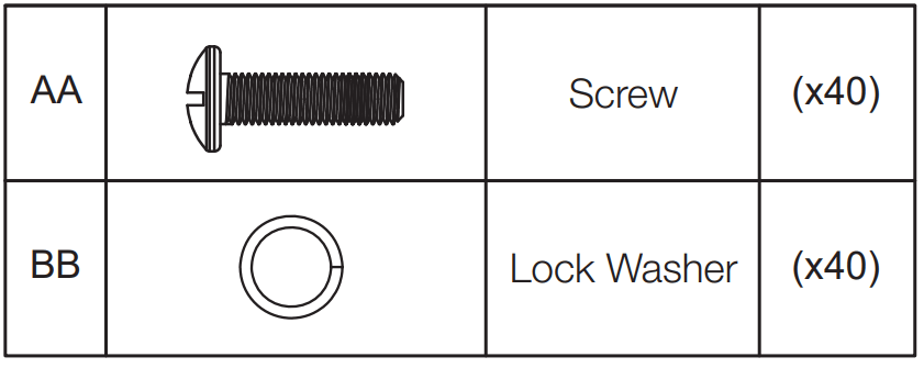
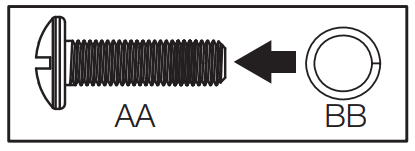
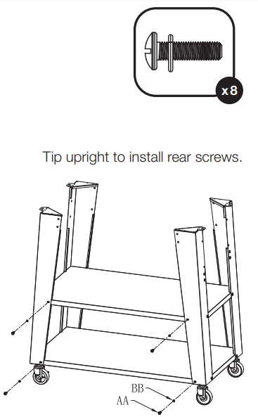
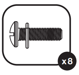
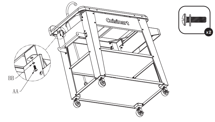
To create “screw assemblies” for future steps, install all 40 of the lock washers (BB) onto all 40 screws (AA).
Screw Assembly
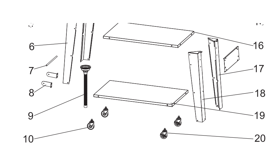
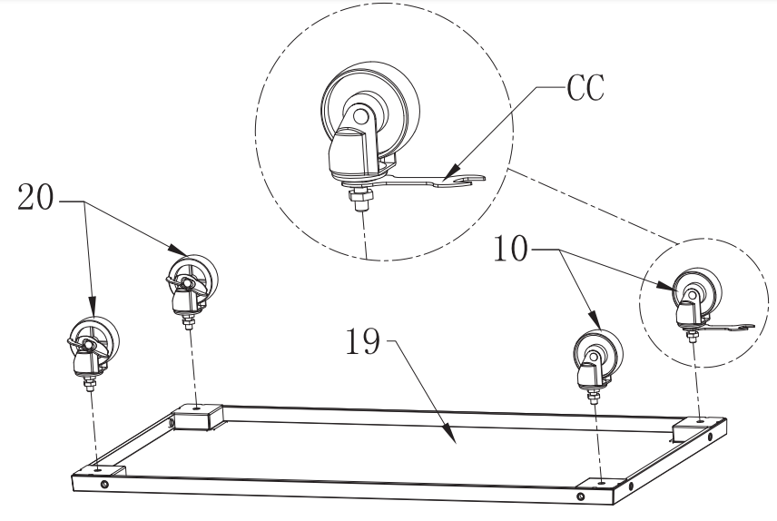
Install locking casters (20) and non locking casters (10) on opposing ends as shown. Use the double-ended open wrench (CC) to attach the 4 casters (20, 10) onto the bottom of the lower shelf (16)
STEP 2
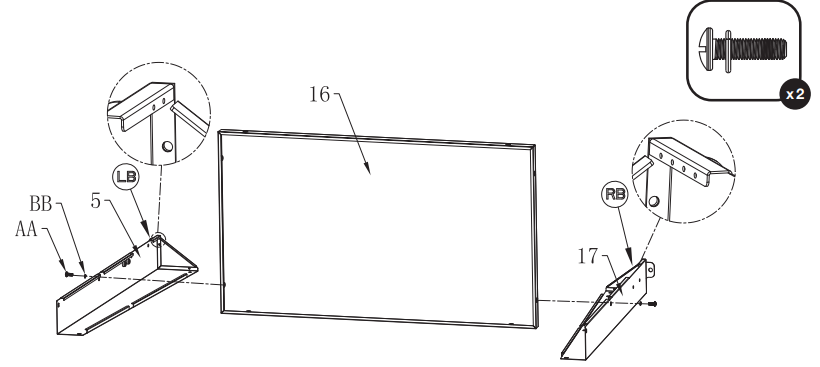
Use screw assemblies to attach the middle portion of left back leg (5) (LB) and the right back leg (17) (RB) to the upper shelf (16) as shown below.
• Note: it is important to not fully tighten the screws during initial assembly of the parts. Wait until the end of step 13 to complete assembly by fully tightening all of the screws.
• Note: Legs are punched with markings to indicate position for assembly, (LB, RB, LF, RF).
• Note: Assembly for the next 4 steps is done with the unit laying on its’ back.
STEP 3
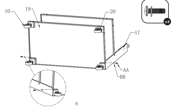
Use screw assemblies to attach the lower shelf (19) assembly to the lower portion of the left back leg (5) (LB) and the right back leg (17) (RB). Note that the locking casters (20) are to the right and only side screws are installed into the legs for this step.
STEP 4
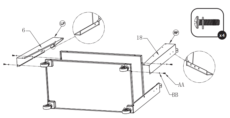
Use screw assemblies to attach the left front leg (6) (LF) and the right front leg (18) (RF) to the lower shelf (19) and the upper shelf (16). Note that only side screws are installed into the legs for this step.
STEP 5
Use screw assemblies to complete attachment of all four legs as shown.
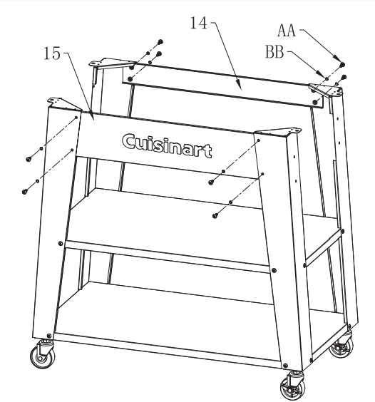
STEP 6
Use screw assemblies to attach name plate (15) to the left front leg (6) (LF) and the right front leg (18) (RF). Next use screw assemblies to attach the rear support to the left back leg (5) (LB) and the right back leg (17) (RB).
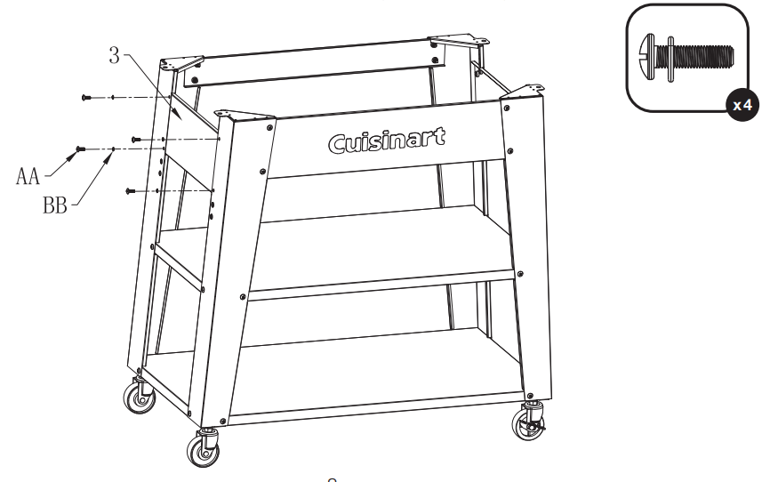
STEP 7
Use screw assemblies to attach the side panel (3) to the left leg assembly using four screws
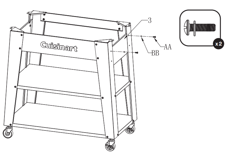
STEP 8
Use screw assemblies to attach the side panel (3) to the right leg assembly using just the top two screws. Install these screws only half way in to allow for parts to be assembled in the next step.
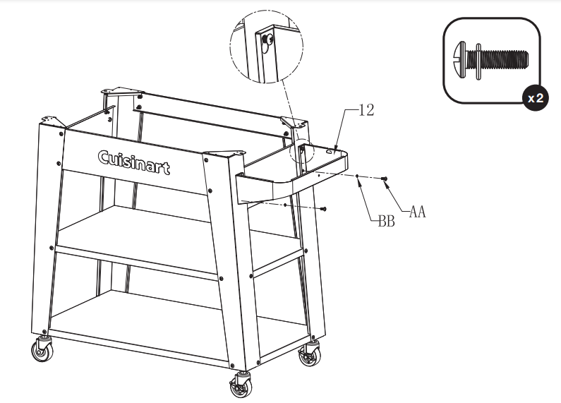
STEP 9
Use screw assemblies to attach the garbage bag support (12) to the right leg assembly using the two previously installed screws and the slotted upper holes. Then install two screws in the lower holes to secure in place.
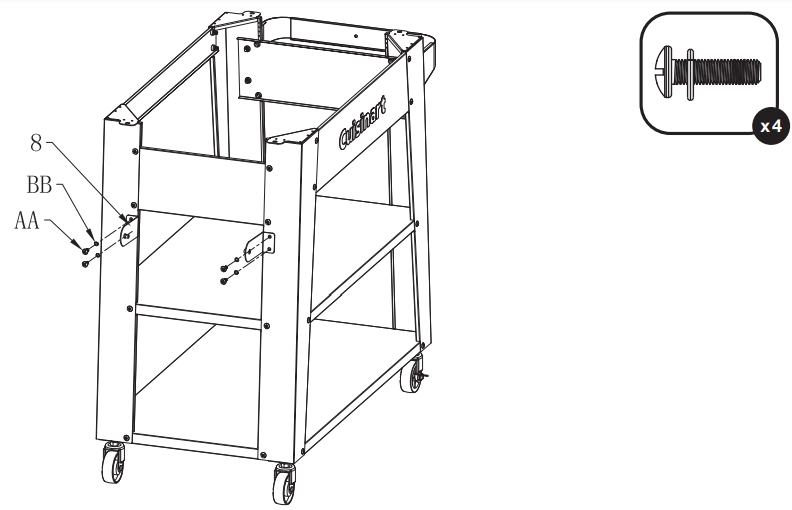
STEP 10
Use screw assemblies to attach both of the towel bar ends (8) to the left leg assembly.
STEP 11
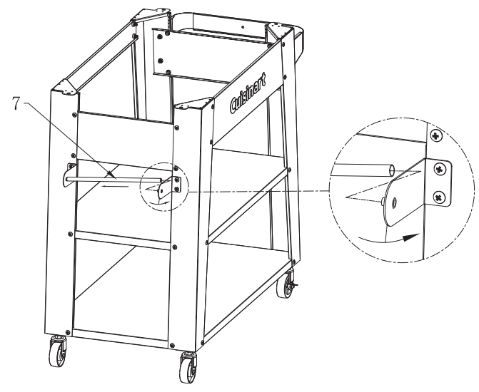
Install the paper towel bar (7) between the two towel bar ends (8) by flexing them slightly outward inserting bar and releasing.
STEP 12
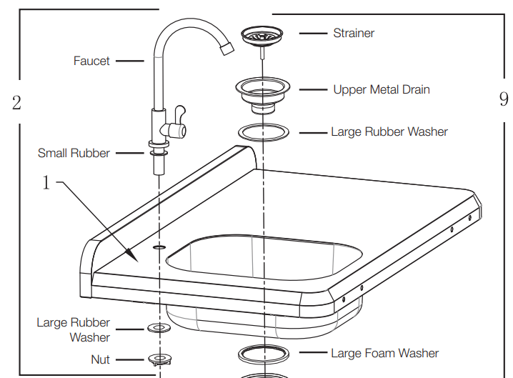
Install the faucet assembly (2) into the counter top assembly (1) by inserting the faucet and small rubber washer in from the top and then securing from the bottom with the large rubber washer and nut. Complete by screwing the supply hose (4) onto the bottom of the faucet and tightening. Hand tightening is all that is required for these components.
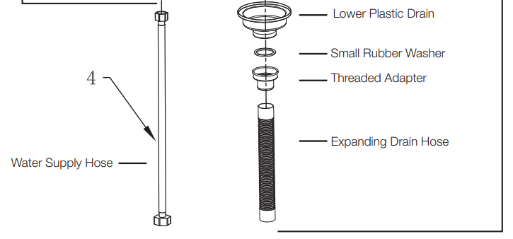
Install the drain assembly (9) into the sink portion of the counter top assembly (1) by inserting the upper metal drain and large rubber washer from the top. Next, from the bottom, install the large foam washer and lower plastic drain followed by the small rubber washer and threading on the threaded adaptor. Complete by pressing the drain hose on until it bottoms out on the threaded adaptor. Hand tightening is all that is required for these components.
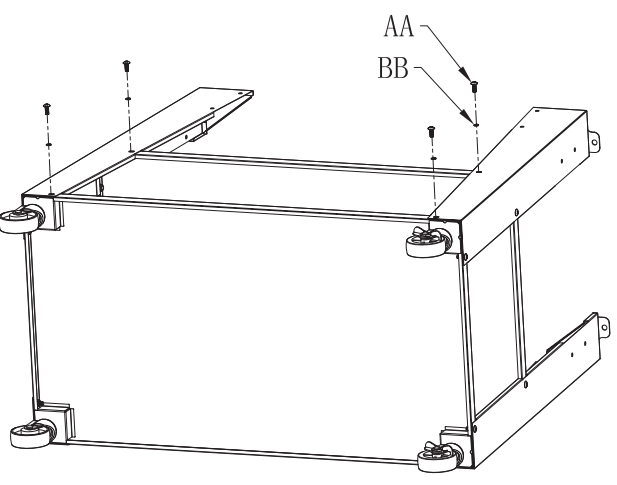
STEP 13
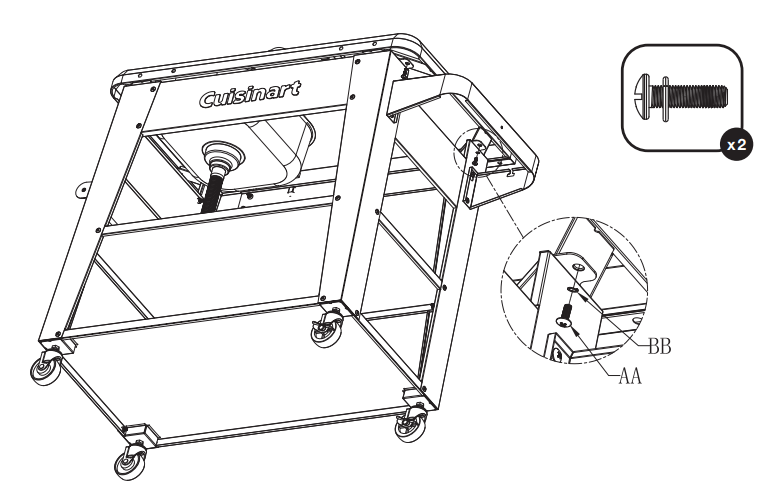
Use screw assemblies to attach the counter top assembly (1) to the prep station base. Now tighten all screw assemblies that have been installed throughout the unit.
STEP 14
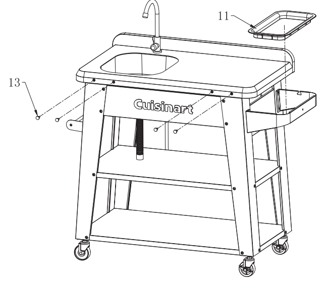
Install the utensil hangers by screwing them into the front edge of the counter top assembly (1). Place the garbage bag ring (11) into the garbage bag support (12).
STEP 15
Once the completed prep table is in its’ desired location use the threaded posts of the casters (10, 20) to level the table and lock nuts with the double-ended open wrench (CC) to hold the adjusted position.
STEP 16
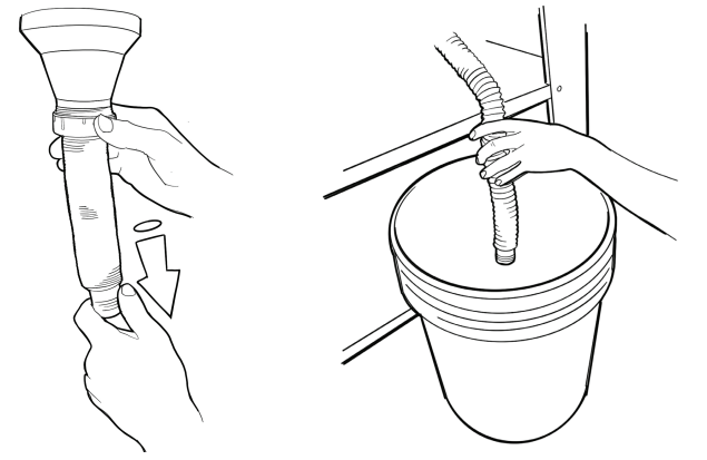
Increase the length of the expanding drain hose by pulling the lower open end of the tube while holding firm the top end that is pressed onto the threaded adaptor. Next position a bucket (not included) close by and place the end of the expanded hose into the bucket. This bucket will serve to catch the waste water.
STEP 17
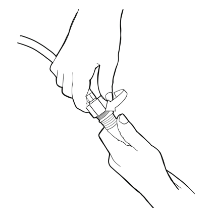
Screw the end of the water supply hose onto a garden hose that is attached to a water supply source. Make sure the faucet is off and turn on the garden hose and check for leaks. If there are leaks turn off the garden hose, tighten the leaking fittings and repeat this step until are seals are tight and not leaking.
STEP 18
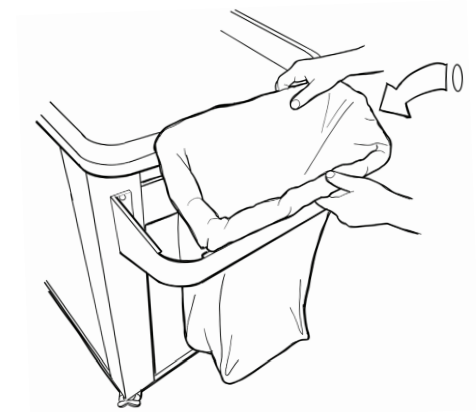
Install a garbage bag by inserting the bag through the garbage bag ring (11) and then wrapping the open end of the bag around the ring. Feed the bottom of the bag through the garbage bag support (12) and then place the garbage bag ring (11), with the opening of the bag wrapped around it, into the garbage bag support (12).
STEP 19
Pull the bag from its’ bottom to ensure it is fully secured by the garbage bag ring (11) and garbage bag support (12).
CARE AND MAINTENANCE
CLEANING
Painted and Plastic surfaces
Wash with mild detergent or non-abrasive cleaner and warm water.
Stainless steel surfaces
Wash with mild detergent and warm soapy water or use a stainless steel cleaner. Wipe dry with a soft cloth after each use. Wash only in the direction of the stainless brushed finish to avoid damage.
Stainless steel can rust under certain conditions. This can be caused by acidic marinades, chlorine, saltwater, exposure to coastal climates, other natural elements, or improper cleaning tools such as wire or steel wool.
Faucet
If faucet ever becomes clogged, turn off the water supply, unscrew the faucet tip, clean the screen and reinstall.