Owners' Guide Coffee Makers
TROUBLESHOOTING
A troubleshooting guide is provided to suggest probable causes and remedies for the most likely problems encountered. If the problem remains after exhausting the troubleshooting steps, contact the Bunn-O-Matic Technical Service Department.
- Inspection, testing, and repair of electrical equipment should be performed only by qualified service personnel.
- This brewer is heated at all times. Keep away from combustibles.
WARNING
- Exercise extreme caution when servicing electrical equipment.
- Unplug the brewer when servicing, except when electrical tests are specified.
- Follow recommended service procedures
- Replace all protective shields or safety notices
| PROBLEM |
PROBABLE CAUSE |
REMEDY |
| Water is not hot |
Limit Thermostat or Thermal Cut-Off CAUTION - Do not eliminate or bypass limit thermostat/thermal cut-off. Use only BOM replacement part.
|
Refer to Service - Limit Thermostat or Thermal Cut-Off for testing procedures. See page 10 or 13 |
|
Control Thermostat
|
Refer to Service - Control Thermostat for testing procedures. See page 9 |
|
Tank Heater
|
Refer to Service - Tank Heater for testing procedures. See page 12 |
| Spitting or excessive steaming |
Lime Build-up
CAUTION - Tank and tank components should be delimed regularly depending on local water conditions. Excessive mineral build-up on stainless steel surfaces can initiate corrosive reactions resulting in serious leaks. |
Inspect the tank assembly for excessive lime deposits. Delime as required. |
| Control Thermostat |
Refer to Service - Control Thermostat for testing procedures.
Inspect the tank assembly for excessive lime deposits. Delime as required.
|
| Dripping from sprayhead |
Lime Build-up
CAUTION - Tank and tank components should be delimed regularly depending on local water conditions. Excessive mineral build-up on stainless steel surfaces can initiate corrosive reactions resulting in serious leaks. |
Excessive lime deposits. Delime as required. |
| Beverage overflows dispenser |
Dispenser |
The dispenser must be completely empty before starting a brew cycle. |
| Weak beverage |
Filter Type |
BUNN® paper filters must be used for proper extraction. |
| Coffee Grind |
A fine or drip grind must be used for proper extraction. |
| Sprayhead |
A six-hole stainless steel sprayhead must be used for proper extraction. |
| Funnel Loading |
The BUNN® paper filter must be centered in the funnel and the bed of grounds leveled by gentle shaking. |
| Water Temperature |
Place an empty funnel on an empty dispenser beneath the sprayhead. Pour-in a pitcher of tap water and check the water temperature immediately below the sprayhead with a thermometer. The reading should not be less than 195°F. Adjust the control thermostat to increase the water temperature. Replace if necessary |
| Dry coffee grounds remain in the funnel |
Funnel Loading |
The BUNN® paper filter must be centered in the funnel and the bed of grounds leveled by gently shaking. |
| Sprayhead plugged |
Clean/verify that sprayhead holes are not plugged. |
| Brewer is making unusal noises |
Tank Heater |
Clean lime off the tank heater |
| Cool beverage serving temperature |
ON/OFF Warmer Switch |
Refer to Service - ON/OFF Warmer Switch for testing procedures. |
| Warmer Element(s) |
Refer to Service - Warmer Element(s) for testing procedures. |
COMPONENT ACCESS
WARNING - Disconnect the brewer from the power source before the removal of any panel or the replacement of any component.
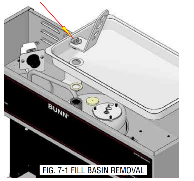
All components are accessible by the removal of the top cover, fill basin and warmer assemblies.
The top cover is attached with two #4-40 screws.
The tank inlet fitting secures the fill basin to the tank lid. Basin wrench 01060.0000 shown.

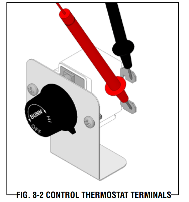
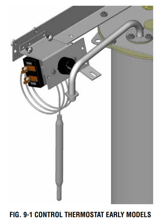
CONTROL THERMOSTAT

Location:
The control thermostat is located inside the hood.
Test Procedures:
- Disconnect the brewer from the power source.
- Locate the black wire on the control thermostat.
- Check the voltage across the black wire on the control thermostat and the white wire on the tank heater or the red wire on the tank heater with a voltmeter. Plug-in the brewer to the power source. The indication must be: a) 120 volts ac for two wire 120 volt models. b) 220 volts ac for two wire 220 volt models.
- Disconnect the brewer from the power source. If voltage is present as described, proceed to #5. If voltage is not present as described, refer to the wiring diagrams and check the brewer wiring harness.
- Locate the blue/black wire on the control thermostat.
- Gently remove the capillary bulb and grommet from the tank.
- Check the voltage across the blue/black wire of the control thermostat and the white wire on the tank heater or red wire on the tank heater with a voltmeter when the control thermostat is turned "ON" (fully clockwise). Plug-in the brewer to the power source. The indication must be:
a) 120 volts ac for two wire 120 volt models.
b) 220 volts ac for two wire 220 volt models.
Voltage must not be present across these terminals when the thermostat is turned "OFF" (fully counterclockwise).
- Disconnect the brewer from the power source.
If voltage is present as described, reinstall the capillary tube into the tank to the line 4.5" above the bulb, the control thermostat is operating properly. If voltage is not present as described, replace the thermostat.
Alternate Test Procedure:
- Disconnect the brewer from the power source.
- Remove leads from control thermostat terminals.
- Gently remove the capillary bulb and grommet from the tank.
- Check for continuity across the control thermostat terminals. The indication must be:
a) Continuity "ON" (fully clockwise).
b) No continuity "OFF" (fully counterclockwise).
If continuity is not as described, replace the thermostat.
Removal and Replacement:
- Remove leads from control thermostat terminals.
- Remove the thermostat capillary bulb by firmly pulling-up on the capillary at the tank lid. This will disengage the grommet from the tank lid.
- Remove the two #6-32 screws securing the control thermostat to the mounting bracket inside the hood. EARLY MODELS: Remove the two #8-32 screws securing the control thermostat/bracket assembly to the tank lid bracket.
- Slide the grommet to the line 4.5" above the bulb on the new capillary tube.
- Insert the capillary bulb through the hole in the tank lid and press the grommet firmly and evenly so that the groove in the grommet fits into the tank lid.
- Carefully bend the capillary tube so that the tube and bulb inside the tank are in the vertical position.
NOTE - The capillary tube must be clear of any electrical termination and not kinked.
- Secure the control thermostat to the mounting bracket.
- Adjust the control thermostat as required
LIMIT THERMOSTAT - VPR, VPS
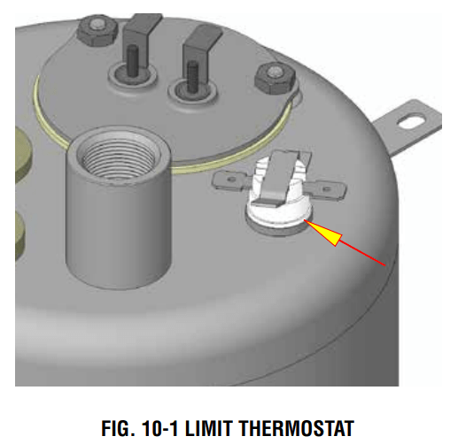
Location:
The limit thermostat is located inside the hood on the right side of the tank lid.
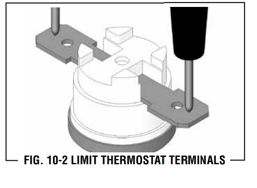
Test Procedures:
- Disconnect the brewer from the power source.
- Disconnect the blue/black and black wires from the limit thermostat.
- Check for continuity across the limit thermostat terminals with an ohmmeter.
If continuity is present as described, the limit thermostat is operating properly.
If continuity is not present as described, replace the limit thermostat.
Removal and Replacement:
- Remove all wires from limit thermostat terminals.
- Carefully slide the limit thermostat out from under the retaining clip and remove limit thermostat.
- Carefully slide the new limit thermostat into the retaining clip.
- Refer to wiring diagram when reconnecting the wires.
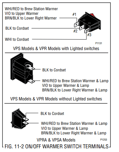
ON/OFF WARMER SWITCH
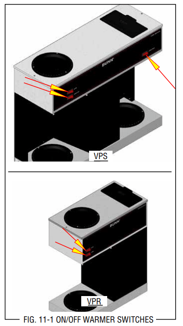
Location:
The ON/OFF warmer switches are located on the front of the hood.
Test Procedure:
- Disconnect the brewer from the power source.
- Viewing the switch from the back locate the black wire from the switch terminal.
- With the switch in the "ON" position check the voltage across the black wire of the switch and the white wire on the lamp or red wire on the lamp with a voltmeter. Plug-in the brewer to the power source. The indication must be:
a) 120 volts ac for two wire 120 volt models.
b) 220 volts ac for two wire 220 volt models.
- Disconnect the brewer from the power source.
If voltage is present as described, proceed to #5.
If voltage is not present as described, refer to the Wiring Diagrams and check the brewer wiring harness.
- Remove both wires from the switch and check for continuity across the terminals with the switch in the "ON" position. Continuity must not be present when the switch is in the "OFF" position.
If continuity is present as described, reconnect the wires to the terminals.
If continuity is not present as described, replace the switch.
Removal and Replacement:
- Remove the wires from the switch terminals.
- Compress the clips inside the hood and gently push the switch through the opening.
- Push the new switch into the opening and spread the clips to hold switch in the hood.
- Refer to Fig. 11-2 when reconnecting the wires
TANK HEATER
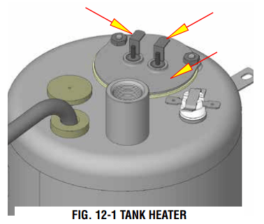
Location:
The tank heater is located inside the tank and secured to the tank lid.
Test Procedures:
- Disconnect the brewer from the power supply.
- Check the voltage across the black and white wires on 120 volt models or the black and red wires for 220 volt models with a voltmeter. Plug the brewer into the power source. The indication must be:
a) *120 volts ac for 120 volt models.
b) *220 volts ac for 220 volt models. (* Control thermostat must be turned on)
- Disconnect the brewer from the power source.
If voltage is present as described, proceed to #4
If voltage is not present as described, refer to the Wiring Diagrams and check wiring harness.
- Disconnect the wires from the heater terminals.
- Check for resistance across the tank heater terminals.
a) 11 ohms (±10%) for 120 volt models.
b) 26 ohms (±10%) for 220 volt models
c) Infinite resistance between either terminal to the housing for all models. Any resistance reading to housing indicates heater is cracked allowing water to short the circuit and must be replaced.
If resistance is present as described, reconnect the wires, the tank heater is operating properly.
If resistance is not present as described, replace the tank heater.
Removal and Replacement:
- Remove the tank inlet fitting securing the fill basin to the tank lid, remove fill basin and tank inlet gasket. Set all three parts aside for reassembly.
- Disconnect the black wire on the terminal block from the tank heater and disconnect the blue/ black wire from the limit thermostat or thermal cut-off to the control thermostat.
- Disconnect the black wire and the white or red wire from the tank heater terminals.
- Remove sprayhead and the hex nut securing the sprayhead tube to the hood. Set aside for reassembly.
- Remove the eight #8-32 nuts securing the tank lid to the tank.
- Remove the tank lid with limit thermostat or thermal cut-off, sprayhead tube and tank heater.
- Remove the two hex nuts securing the tank heater to the tank lid. Remove tank heater with gaskets and discard.
- Install new tank heater with gaskets on the tank lid and secure with two hex nuts.
- Install tank lid with limit thermostat or thermal cut-off, sprayhead tube and tank heater using eight #8-32 hex nuts.
- Secure sprayhead tube to hood using a hex nut.
- Install sprayhead.
- Reconnect the wires to the limit thermostat or thermal cut-off, tank heater and control thermostat. See limit thermostat, thermal cut-off and control thermostat sections in this manual when reconnecting wires.
- Install fill basin, secure with tank inlet fitting and gasket.
- Refer to wiring diagram when reconnecting the tank heater wires.
THERMAL CUT-OFF - VPRA, VPSA
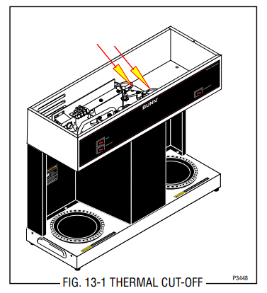
Location:
The thermal cut-outs are located inside the hood connected to the tank heater terminals.
Test Procedures:
- Disconnect the brewer from the power source.
- Disconnect the thermal cut-off from the tank heater and the red wire from the power connector.
- Check for continuity across the thermal cut-off terminals with an ohmmeter.
If continuity is present as described, the thermal cutoff is operating properly.
If continuity is not present as described, replace the thermal cut-off.
- Disconnect the thermal cut-off from the tank heater and blue/black from the control thermostat.
- Check for continuity across the thermal cut-off terminals with an ohmmeter.
If continuity is present as decribed, the thermal cut-off is operating properly.
If continuity is not present as described, replace the thermal cut-off.
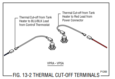
Removal and Replacement:
- Disconnect the thermal cut-off from the tank heater and the red wire from the power connector or the blue/black wire from the control thermostat.
- Install new thermal cut-off.
- Refer to Fig. 13-2 when reconnecting wires.
WARMER ELEMENTS
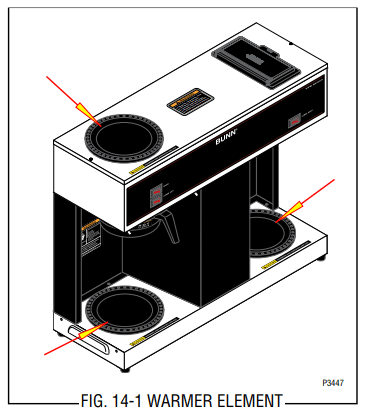
Location:
The warmer elements are located under the warmer plates.
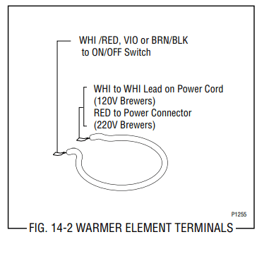
Test Procedures:
- Disconnect the brewer from the power source.
- Use the white to the power cord or red wire to the power connector and the white/red, violet or brown/black wire on the "ON/OFF" switch.
- Check voltage across the white or red and white/ red, violet or brown/black with a voltmeter with the "ON/OFF" switch in the "ON" position. Plug-in the brewer to the power source. The indication must be:
a) 120 volts ac for two wire 120 volt models.
b) 220 volts ac for two wire 220 volt models.
- Disconnect the brewer from the power source.
If voltage is present as described, proceed to #5.
If voltage is not present as described, refer to wiring diagrams and check brewer wiring harness.
- Remove both wires from the warmer element and check the continuity across the two terminals on the warmer element.
If continuity is present as described, reconnect the wires on the warmer element.
If continuity is not present as described, replace the warmer element.
Removal and Replacement:
- Remove the three #4-40 screws securing the warmer assembly to the brewer.
- Lift the warmer assembly from the brewer.
- Disconnect the two wires from the warmer element terminals.
- Remove the two #8-32 nuts securing the warmer element to the warmer plate.
- Securely install new warmer element.
- Reconnect the two wires to warmer element terminals.
- Securely install warmer assembly on the brewer.
- Refer to Fig. 14-2 when reconnecting the wires.
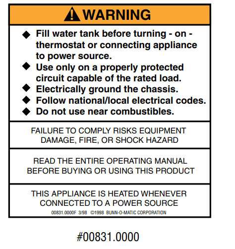
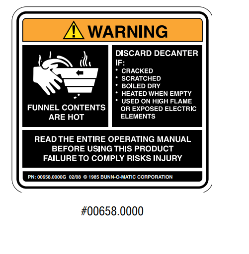
USER NOTICES
Carefully read and follow all notices in this manual and on the equipment. All labels on the equipment should be kept in good condition. Replace any unreadable or damaged labels

ELECTRICAL REQUIREMENTS
CAUTION - The brewer must be disconnected from the power source until specified in Initial Set-Up.
The brewer has an attached cordset and requires 2-wire grounded service rated 120 volts ac, 15 amp, single phase, 60 Hz.
INITIAL SET-UP
CAUTION- The brewer must be disconnected from the power source throughout the initial set-up, except when specified in the instructions.
- Insert an empty funnel into the funnel rails.
- Place an empty dispenser under the funnel.
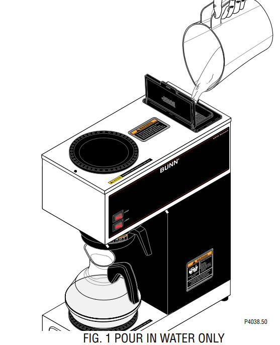
- Open the flip lid on top of the brewer and pour in three pitchers of tap water. Allow approximately two minutes between pitchers for water to flow into the tank. While the third pitcher of water is entering the tank, the tank will fill to capacity and the excess will flow from the sprayhead, out of the funnel, and into the dispenser. FIG. 1
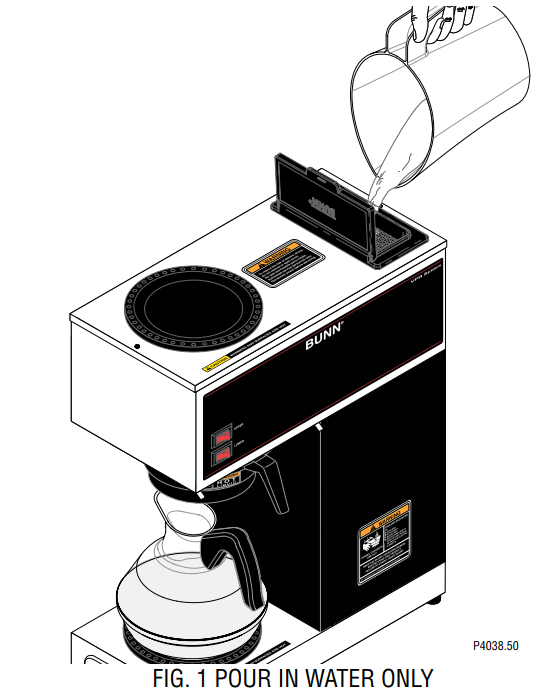
- When the flow of water from the funnel stops, connect the brewer to the power source and wait approximately twenty minutes for the water in the tank to heat to the proper temperature. Some water will drip from the funnel during this time; this is due to expansion and should not occur thereafter.
- Empty the dispenser and replace it under the funnel.
- Open the flip lid on top of the brewer and pour in one pitcher of tap water.
- When water has stopped flowing from the funnel let the water in the tank reheat to the proper temperature.
- Empty the dispenser. The brewer is now ready for use in accordance with the coffee brewing instructions below. NOTE: The control thermostat will need to be adjusted downward to compensate for high altitudes. Refer to Service Manual for instructions.
COFFEE BREWING
- Insert a BUNN® filter into the funnel.
- Pour the fresh coffee into the filter and level the bed of grounds by gently shaking.
- Slide the funnel into the funnel rails.
- Place an empty dispenser beneath the funnel. Models with warmers - Turn on lower warmer switch.
- Open the flip lid on top of the brewer and pour in one pitcher of tap water. FIG. 1
- When brewing is completed, simply discard the grounds and filter
CLEANING
- The use of a damp cloth rinsed in any mild, non-abrasive, liquid detergent is recommended for cleaning all surfaces on Bunn-O-Matic equipment.
- Check and clean the sprayhead. The sprayhead holes must always remain open.
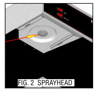
- With the sprayhead removed, insert the deliming spring (provided) all the way into the sprayhead tube. When inserted properly, no more than two inches of spring should be visible. Saw back and forth five or six times.
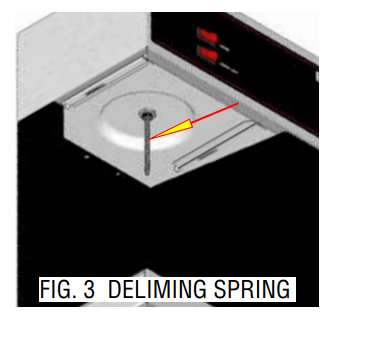
NOTE – In hard water areas, this may need to be done daily. It will help prevent liming problems in the brewer and takes less than a minute.