Loading ...
Loading ...
Loading ...
1 Route battery wire from engine com-
partment to the vehicle interior.
! When drilling a cable pass-hole into the ve-
hicle body and routing a battery wire thor-
ough it, take care not to short-circuit the
wire damaging it by the cut edges or burrs
of the hole.
After completing all other amplifier connec-
tions, finally connect the battery wire terminal
of the amplifier to the positive (+) battery
terminal.
2
1
3
1 Positive (+) terminal
2 Battery wire (sold separately)
The maximum length of the wire between
the fuse and the positive + terminal of the
battery is 30 cm (12 in.).
3 Fuse 100 A (GM-D8601) / 150 A (GM-D9601)
(sold separately)
Each amplifier must be separately fused at
100 A (GM-D8601) / 150 A (GM-D9601).
2 Use wire cutters or a utility knife to
strip the end of the battery wire, ground
wire and system remote control wire to ex-
pose about 10 mm (3/8 in.) of the end of
each of the wires, and then twist the ex-
posed ends of the wires.
Twist
10 mm (3/8in.)
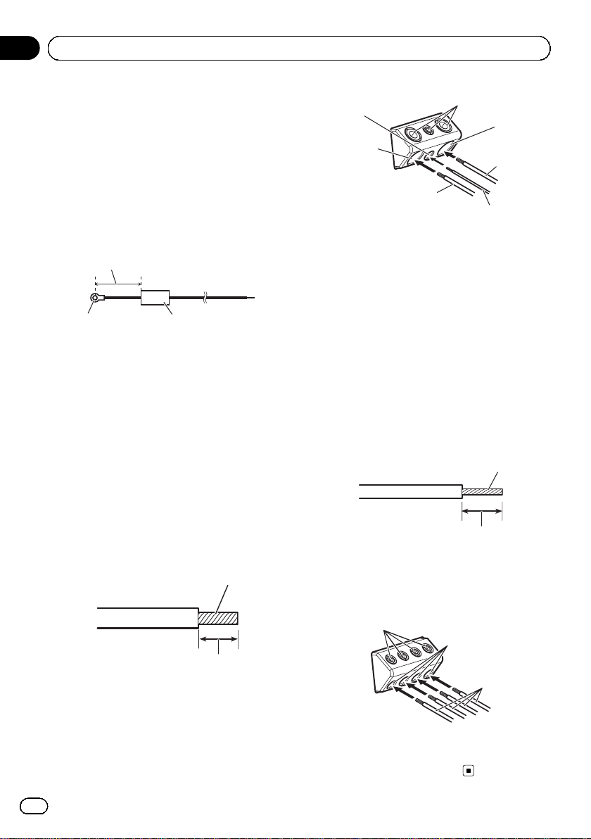
3 Connect the wires to the terminal.
Fix the wires securely with the terminal
screws.
3
6
1
5
4
2
7
1 Battery wire
2 Power terminal
3 Ground wire
4 GND terminal
5 System remote control wire
6 System remote control terminal
7 Terminal screws
Connecting the speaker output
terminals
1 Use wire cutters or a utility knife to
strip the end of the speaker wires to ex-
pose about 10 mm (3/8 in.) of wire and
then twist the wire.
Twist
10 mm (3/8in.)
2 Connect the speaker wires to the
speaker output terminals.
Fix the wires securely with the terminal
screws.
1
3
2
1 Terminal screws
2 Speaker wires
3 Speaker output terminals
En
10
Section
03
Connecting the units
15090307701-B<10>
Loading ...
Loading ...
Loading ...