Loading ...
Loading ...
Loading ...
10
ON / OFF
MASTER SWITCH
P11
M2
M1
SW2
P10
COM A COM B
P12
P13
IAT
BLACK
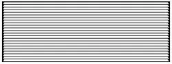
DS1 DS2 MS1 MS2 EH IN LS FD1 FD2 TF- TF+ C R GL W2 Y/W1 B GH
REM OTE THERMOS TATAUXILIARY
Control Board User Inputs*
*NOTE: The PTAC Wire Harness Kit (PWHK01C) is required for the auxiliary or remote thermostat options.
ADDITIONAL CONTROL INPUTS
The control inputs shown above provide additional unit control
and features. To access these control inputs, the cabinet front
must be removed (see Front Removal).
MASTER SWITCH
The master switch disconnects power to all of the system
components. When this switch is in the off position, the compres-
sor, fan motor, reversing valve, and electric resistance heater will
all be de-energized.
WARNING
T
O PREVENT PROPERTY DAMAGE, PERSONAL INJURY OR DEATH DUE TO
ELECTRIC SHOCK, UNPLUG THE UNIT AT THE WALL OUTLET OR TURN OFF
POWER AT THE FUSE BOX OR CIRCUIT BREAKER BEFORE SERVICING THE
UNIT.
L
INE VOLTAGE WILL BE PRESENT AT THE CONTROL BOARD, TERMINALS
L
1 AND
L
2, WHENEVER POWER IS APPLIED TO THE UNIT REGARDLESS OF
THE MASTER SWITCH POSITION.
REMOTE CONTROL INPUTS
The C, R, GL, W2, Y/W1, B/O, and GH terminals provide control
inputs for a “manufacturer-approved” remote wall mounted
thermostat. The “B” terminal can be configured to become “O” if
needed see Configuration Settings For remote control thermostat
operation, refer to the Remote Thermostat Operation section.
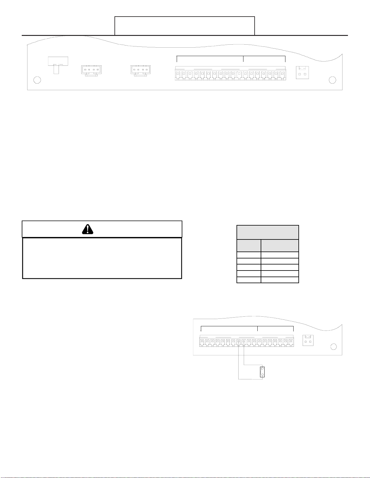
FRONT DESK CONTROL (FD1, FD2, EH, IN)
The FD1, FD2, EH and IN terminals provide control inputs for a
front desk switch. Shorting across the FD1 and FD2 terminals
will disable unit operation. The only control function which will
remain active when these terminals are shorted is freeze protec-
tion. Any switch which will produce a short circuit across these
two terminals can be used as a front desk switch. The contact
resistance of the switch, when closed, must be less than 200
ohms for the front desk feature to operate properly. Table 3
shows the maximum wire length and corresponding gage size for
installation of a front desk switch. The following figure shows a
wiring schematic for connecting the front desk switch to the unit.
If the unit is configured for wired unrented setback energy
management (see Configuration Settings section c2), EH and IN
terminals are used instead of FD1 and FD2. If EH and IN are
shorted, the unit will go into setback temperatures for cooling and
heating as configured in c3 and c4 (see Configuration Settings).
Unit operation will be disabled. “Fd” (see Diagnostic Codes) will
appear on the display. This allows the room to quickly recover to
a comfortable temperature when the room is occupied.
Maximum Wire
Len
g
th
Wire Size
(AWG)
Maximum Length
Allowed
#24 400 ft
#22 600 ft
#20 900 ft
#18 1500 ft
#16 2000 ft
Table 3 - Maximum Wire Length for
Front Desk Switch
M2
FRONT
DESK
SWITCH
IAT
BLACK
DS1 DS2 MS1 MS2 EH IN LS FD1 FD2 TF- TF+ C R GL W2 Y/W1 B GH
REMOTE THERMOSTATAUXILIARY
Front Desk Switch Wiring Schematic
Operating Instructions
Loading ...
Loading ...
Loading ...