Loading ...
Loading ...
Loading ...
Piping
43 Liebert
®
SRC™ User Manual
3. Calculate the difference in the two expansion distance values.
The result is the anticipated change in pipe length.
Example:
A system is installed and the design shows that there is a 100-foot straight segment of tubing between an
indoor unit and the outdoor unit. When heating, this pipe transports hot gas vapor to the indoor units at
120°F. When cooling, the same tube is a suction
line that returns refrigerant vapor to the outdoor unit at
40°F. Look-up the copper-tubing expansion at each temperature and calculate the difference.
Vapor L ine
Transporting hot vapor: 100-ft pipe at 120°F = 1.40in.
Transporting suction vapor: 100-ft pipe at 40°F = 0.40in
.
Anticipated change in length: 1.40in. – 0.40in. = 1.00 in.
Liquid Line
The liquid temperature remains relatively the same temperature, only direction of flow reverses. Therefore,
no significant change in length of the liquid line is anticipated.
When creating an expansion joint, the joint height shoul
d be a minimum of two times the joint width.
Although different types of expansion arrangements are available, the data for correctly sizing an
expansion loop is provided in Table5-8. Use soft copper with long-radius bends on longer runs or long-
radius elbows
for shorter pipe segments. Using the anticipated linear expansion (LE) distance calculated,
look-up the expansion loop or U-bend minimum design dimensions. If you choose to use other types of
expansion joints, design per ASTM B-88 Standards.
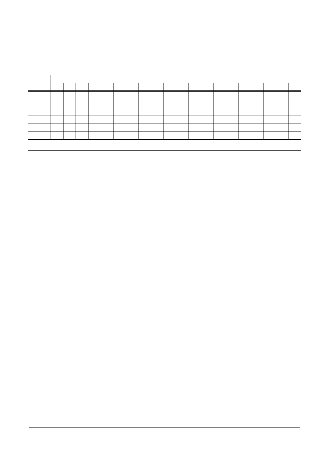
Table 5-7 Linear therma
l expansion of copper tubing, in inches
Pipe
Length
1
Fluid Temperature, °F
35° 40° 45° 50° 55° 60° 65° 70° 75° 80° 85° 90° 95°100°105°110°115°120°125°130°
10
0.04 0.04 0.05 0.06 0.06 0.07 0.08 0.08 0.09 0.09 0.10 0.10 0.11 0.11 0.11 0
.12 0.13 0.14 0.15 0.15
20
0.08 0.08 0.10 0.12 0.13 0.14 0.15 0.16 0.17 0.18 0.19 0.20 0.21 0.22 0.22 0.23 0.26 0.28 0.29 0.30
30
0.12 0.12 0.15 0.18 0.20 0.21 0.23 0.24 0.26 0.27 0.29 0.30 0.32 0.33 0.32 0.35 0.39 0.4
20.44 0.45
40
0.16 0.16 0.20 0.24 0.26 0.28 0.30 0.32 0.34 0.36 0.38 0.400.420.44 0.430.46 0.52 0.56 0.58 0.60
50
0.20 0.20 0.25 0.30 0.33 0.35 0.38 0.400.430.450.480.50 0.53 0.55 0.54 0.58 0.
650.70 0.73 0.75
60
0.24 0.24 0.30 0.36 0.39 0.420.450.480.51 0.54 0.57 0.600.630.66 0.650.690.78 0.84 0.87 0.90
1. Pipe length baseline temperature = 0°F. “Expansion of Carbon, Copper and Stainless Steel Pipe,” The Engineer’s Toolbox,
www.engineeringtoolbox.com.
MFL67502030 17. 7. 13. 오오 3:05 Page 53
Loading ...
Loading ...
Loading ...