Liebert
®
SRC
™
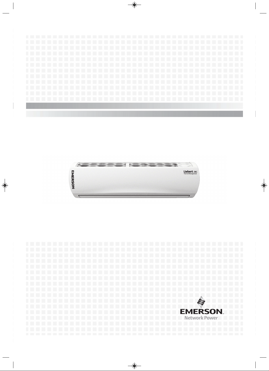
User Manual—Mini-Split Cooling System
MFL67502030 17. 7. 13. 오오 3:05 Page 1

MFL67502030 17. 7. 13. 오오 3:05 Page 2

i Liebert SRC
™
User Manual
Table of Content
Important Safety Instructions. . . . . . . . . . . . . . . . . . . . . . . . . . . . . . . . . . . . . . 1
Safety Symbols . . . . . . . . . . . . . . . . . . . . . . . . . . . . . . . . . . . . . . . . . . . . . . . . . 7
1.0 Model Number and Nomenclature . . . . . . . . . . . . . . . . . . . . . . . . . . . . . . . 9
2.0 Product Introduction . . . . . . . . . . . . . . . . . . . . . . . . . . . . . . . . . . . . . . . . . 11
2.1 Electrical Data . . . . . . . . . . . . . . . . . . . . . . . . . . . . . . . . . . . . . . . . . . . . . . . . . . . . . . . . . . 16
2.2 R410A Refrigerant. . . . . . . . . . . . . . . . . . . . . . . . . . . . . . . . . . . . . . . . . . . . . . . . . . . . . . . 17
3.0 Installation . . . . . . . . . . . . . . . . . . . . . . . . . . . . . . . . . . . . . . . . . . . . . . . . . 19
3.1 Selecting the Location for the Outdoor Unit . . . . . . . . . . . . . . . . . . . . . . . . . . . . . . . . . . . 19
3.1.1 Ambient air conditions. . . . . . . . . . . . . . . . . . . . . . . . . . . . . . . . . . . . . . . . . . . . . . . . . . . . 20
3.1.2 Oceanside Applications . . . . . . . . . . . . . . . . . . . . . . . . . . . . . . . . . . . . . . . . . . . . . . . . . . 20
3.2 Mounting the Outdoor Unit . . . . . . . . . . . . . . . . . . . . . . . . . . . . . . . . . . . . . . . . . . . . . . . . 23
3.2.1 Mounting Platform. . . . . . . . . . . . . . . . . . . . . . . . . . . . . . . . . . . . . . . . . . . . . . . . . . . . . . . 23
3.2.2 Tie-downs and Wind Restraints . . . . . . . . . . . . . . . . . . . . . . . . . . . . . . . . . . . . . . . . . . . . 23
3.2.3 Snow and Ice Conditions . . . . . . . . . . . . . . . . . . . . . . . . . . . . . . . . . . . . . . . . . . . . . . . . . 24
3.3 Clearance requirements . . . . . . . . . . . . . . . . . . . . . . . . . . . . . . . . . . . . . . . . . . . . . . . . . . 24
3.3.1 Outdoor Unit Clearance . . . . . . . . . . . . . . . . . . . . . . . . . . . . . . . . . . . . . . . . . . . . . . . . . . 24
3.3.2 Indoor Unit Clearance . . . . . . . . . . . . . . . . . . . . . . . . . . . . . . . . . . . . . . . . . . . . . . . . . . . . 26
3.4 Installing the Indoor Unit . . . . . . . . . . . . . . . . . . . . . . . . . . . . . . . . . . . . . . . . . . . . . . . . . . 26
3.4.1 Mounting the Installation Plate to the Wall (SRC18). . . . . . . . . . . . . . . . . . . . . . . . . . . . . 26
3.4.2 Mounting the Installation Plate to the Wall (SRC24, SRC36) . . . . . . . . . . . . . . . . . . . . . . 28
3.4.3 Drilling a Piping Hole in the Wall. . . . . . . . . . . . . . . . . . . . . . . . . . . . . . . . . . . . . . . . . . . . 29
3.4.4 Mounting the Indoor Unit to the Plate . . . . . . . . . . . . . . . . . . . . . . . . . . . . . . . . . . . . . . . . 29
3.4.5 Prepare for Piping/Electrical Connection . . . . . . . . . . . . . . . . . . . . . . . . . . . . . . . . . . . . . 30
3.5 Pump Down Procedure . . . . . . . . . . . . . . . . . . . . . . . . . . . . . . . . . . . . . . . . . . . . . . . . . . . 31
4.0 Installation Checklist. . . . . . . . . . . . . . . . . . . . . . . . . . . . . . . . . . . . . . . . . 33
5.0 Piping . . . . . . . . . . . . . . . . . . . . . . . . . . . . . . . . . . . . . . . . . . . . . . . . . . . . . 35
5.1 Piping Preparation. . . . . . . . . . . . . . . . . . . . . . . . . . . . . . . . . . . . . . . . . . . . . . . . . . . . . . . 35
5.1.1 Creating a Flare Fitting . . . . . . . . . . . . . . . . . . . . . . . . . . . . . . . . . . . . . . . . . . . . . . . . . . . 35
5.1.2 Tightening Flare Nuts . . . . . . . . . . . . . . . . . . . . . . . . . . . . . . . . . . . . . . . . . . . . . . . . . . . . 37
5.1.3 Loosening Flare Nuts . . . . . . . . . . . . . . . . . . . . . . . . . . . . . . . . . . . . . . . . . . . . . . . . . . . . 38
MFL67502030 17. 7. 13. 오오 3:05 Page 3
Liebert SRC
™
User Manual ii
5.2 Piping Materials and Handling. . . . . . . . . . . . . . . . . . . . . . . . . . . . . . . . . . . . . . . . . . . . . . 38
5.2.1 Brazing Practices . . . . . . . . . . . . . . . . . . . . . . . . . . . . . . . . . . . . . . . . . . . . . . . . . . . . . . . 39
5.2.2 Refrigerant-piping System Insulation . . . . . . . . . . . . . . . . . . . . . . . . . . . . . . . . . . . . . . . . 40
5.2.3 Selecting Field-supplied Copper Tubing . . . . . . . . . . . . . . . . . . . . . . . . . . . . . . . . . . . . . . 40
5.2.4 No Pipe Size Substitutions . . . . . . . . . . . . . . . . . . . . . . . . . . . . . . . . . . . . . . . . . . . . . . . . 41
5.2.5 Obstacles . . . . . . . . . . . . . . . . . . . . . . . . . . . . . . . . . . . . . . . . . . . . . . . . . . . . . . . . . . . . . 42
5.2.6 Copper Expansion and Contraction . . . . . . . . . . . . . . . . . . . . . . . . . . . . . . . . . . . . . . . . . 42
5.2.7 P
ipe Bends . . . . . . . . . . . . . . . . . . . . . . . . . . . . . . . . . . . . . . . . . . . . . . . . . . . . . . . . . . . . 44
5.2.8 In-line Refrigeration Components . . . . . . . . . . . . . . . . . . . . . . . . . . . . . . . . . . . . . . . . . . . 44
5.2.9 Field-provided Isolation Ball Valves . . . . . . . . . . . . . . . . . . . . . . . . . . . . . . . . . . . . . . . . . 45
5.2.10 Using Elbows . . . . . . . . . . . . . . . . . . . . . . . . . . . . . . . . . . . . . . . . . . . . . . . . . . . . . . . . . 45
5.2.11 Pipe Supports . . . . . . . . . . . . . . . . . . . . . . . . . . . . . . . . . . . . . . . . . . . . . . . . . . . . . . . . . 45
5.2.12 Pipe Sleeves at Penetrations . . . . . . . . . . . . . . . . . . . . . . . . . . . . . . . . . . . . . . . . . . . . . 47
5.2.13 Underground Refrigerant Piping . . . . . . . . . . . . . . . . . . . . . . . . . . . . . . . . . . . . . . . . . . . 48
5.3 Piping Connections . . . . . . . . . . . . . . . . . . . . . . . . . . . . . . . . . . . . . . . . . . . . . . . . . . . . . . 49
5.3.1 Connection Limitations . . . . . . . . . . . . . . . . . . . . . . . . . . . . . . . . . . . . . . . . . . . . . . . . . . . 49
5.3.2 Piping Connections Layout . . . . . . . . . . . . . . . . . . . . . . . . . . . . . . . . . . . . . . . . . . . . . . . . 50
5.3.2.1 Pipe bundling . . . . . . . . . . . . . . . . . . . . . . . . . . . . . . . . . . . . . . . . . . . . . . . . . . . 51
5.3.2.2 Bundling and Trap when Indoor Unit is above Outdoor Unit . . . . . . . . . . . . . . . 52
5.3.2.3 Bundling and Trap when Indoor Unit is below Outdoor Unit . . . . . . . . . . . . . . . 52
5.3.3 Routing the
Drain Hose for Indoor Unit. . . . . . . . . . . . . . . . . . . . . . . . . . . . . . . . . . . . . . . 53
5.3.4 Installing a Drain Hose on the Outdoor Unit . . . . . . . . . . . . . . . . . . . . . . . . . . . . . . . . . . . 54
5.3.5 Connecting Piping on the SCR18 Outdoor Unit . . . . . . . . . . . . . . . . . . . . . . . . . . . . . . . . 55
5.3.6 Connecting Piping on the SCR24 and SCR36 Outdoor Unit . . . . . . . . . . . . . . . . . . . . . . 57
5.3.7 Connecting P
iping on the Indoor Unit . . . . . . . . . . . . . . . . . . . . . . . . . . . . . . . . . . . . . . . . 59
5.4 Piping Insulation . . . . . . . . . . . . . . . . . . . . . . . . . . . . . . . . . . . . . . . . . . . . . . . . . . . . . . . . 63
5.4.1 Minimum Requirements for Wall Thickness
of Ethylene Propylene Diene Methylene (EPDM) Pipe Insulation . . . . . . . . . . . . . . . . . 65
5.5 Air Purging. . . . . . . . . . . . . . . . . . . . . . . . . . . . . . . . . . . . . . . . . . . . . . . . . . . . . . . . . . . . . 66
5.5.1 Piping Leak Test . . . . . . . . . . . . . . . . . . . . . . . . . . . . . . . . . . . . . . . . . . . . . . . . . . . . . . . . 67
5.5.1.1 Connecting the pressure gauge . . . . . . . . . . . . . . . . . . . . . . . . . . . . . . . . . . . . . 68
5.5.1.2 Soap-and-Water Leak Testing . . . . . . . . . . . . . . . . . . . . . . . . . . . . . . . . . . . . . . 68
5.5.1.3 Ambient Temperature for Leak Test . . . . . . . . . . . . . . . . . . . . . . . . . . . . . . . . . 69
5.5.2 Evacuation . . . . . . . . . . . . . . . . . . . . . . . . . . . . . . . . . . . . . . . . . . . . . . . . . . . . . . . . . . . . 69
5.5.3 Removing Purge and Test Equipment . . . . . . . . . . . . . . . . . . . . . . . . . . . . . . . . . . . . . . . 70
6.0 Electrical Connections . . . . . . . . . . . . . . . . . . . . . . . . . . . . . . . . . . . . . . . 71
6.1 Power-supply/Power-wiring Specifications . . . . . . . . . . . . . . . . . . . . . . . . . . . . . . . . . . . . 72
6.2 Communication-cable Specifications . . . . . . . . . . . . . . . . . . . . . . . . . . . . . . . . . . . . . . . . 74
6.3 Communication Cables between the Unit and Controller . . . . . . . . . . . . . . . . . . . . . . . . . 74
MFL67502030 17. 7. 13. 오오 3:05 Page 4
iii Liebert SRC
™
User Manual
6.4 Connecting Indoor Unit Electrical Wiring. . . . . . . . . . . . . . . . . . . . . . . . . . . . . . . . . . . . . . 75
6.4.1 Terminal-block Connection for SRC18 . . . . . . . . . . . . . . . . . . . . . . . . . . . . . . . . . . . . . . . 77
6.4.2 Terminal-block Connection for SRC24, SRC36 . . . . . . . . . . . . . . . . . . . . . . . . . . . . . . . . 78
6.5 Connecting Outdoor Unit Electrical Wiring . . . . . . . . . . . . . . . . . . . . . . . . . . . . . . . . . . . . 78
6.6 Thermostat Installation and Wiring . . . . . . . . . . . . . . . . . . . . . . . . . . . . . . . . . . . . . . . . . . 81
7.0 Installation Set-up and System Start-up . . . . . . . . . . . . . . . . . . . . . . . . . 85
7.1 Accessing Installer Set-up Mode. . . . . . . . . . . . . . . . . . . . . . . . . . . . . . . . . . . . . . . . . . . . 85
7.2 Running Test Mode. . . . . . . . . . . . . . . . . . . . . . . . . . . . . . . . . . . . . . . . . . . . . . . . . . . . . . 86
7.3 Setting the Address of Central Control . . . . . . . . . . . . . . . . . . . . . . . . . . . . . . . . . . . . . . . 87
7.4 Setting E.S.P. . . . . . . . . . . . . . . . . . . . . . . . . . . . . . . . . . . . . . . . . . . . . . . . . . . . . . . . . . . 87
7.5 Setting the Thermistor. . . . . . . . . . . . . . . . . . . . . . . . . . . . . . . . . . . . . . . . . . . . . . . . . . . . 88
7.6 Setting the Ceiling Height . . . . . . . . . . . . . . . . . . . . . . . . . . . . . . . . . . . . . . . . . . . . . . . . . 89
7.7 Setting Fahrenheit/Celsius . . . . . . . . . . . . . . . . . . . . . . . . . . . . . . . . . . . . . . . . . . . . . . . . 89
7.8 Setting Optional Functions . . . . . . . . . . . . . . . . . . . . . . . . . . . . . . . . . . . . . . . . . . . . . . . . 90
7.9 Setting Temperature Range . . . . . . . . . . . . . . . . . . . . . . . . . . . . . . . . . . . . . . . . . . . . . . . 90
8.0 Operation . . . . . . . . . . . . . . . . . . . . . . . . . . . . . . . . . . . . . . . . . . . . . . . . . . 91
8.1 Operating the Unit . . . . . . . . . . . . . . . . . . . . . . . . . . . . . . . . . . . . . . . . . . . . . . . . . . . . . . . 91
8.2 Automatic Unit Restart . . . . . . . . . . . . . . . . . . . . . . . . . . . . . . . . . . . . . . . . . . . . . . . . . . . 92
8.3 Enabling Cooling-only Mode . . . . . . . . . . . . . . . . . . . . . . . . . . . . . . . . . . . . . . . . . . . . . . . 92
8.4 Disabling Cooling-only Mode. . . . . . . . . . . . . . . . . . . . . . . . . . . . . . . . . . . . . . . . . . . . . . . 93
8.5 Standard Operation. . . . . . . . . . . . . . . . . . . . . . . . . . . . . . . . . . . . . . . . . . . . . . . . . . . . . . 93
8.5.1 Selecting Cooling Mode . . . . . . . . . . . . . . . . . . . . . . . . . . . . . . . . . . . . . . . . . . . . . . . . . . 93
8.5.2 Selecting Power Cooling. . . . . . . . . . . . . . . . . . . . . . . . . . . . . . . . . . . . . . . . . . . . . . . . . . 93
8.5.3 Selecting Heating Mode . . . . . . . . . . . . . . . . . . . . . . . . . . . . . . . . . . . . . . . . . . . . . . . . . . 94
8.5.4 Selecting Dehumidification Mode . . . . . . . . . . . . . . . . . . . . . . . . . . . . . . . . . . . . . . . . . . . 94
8.5.5 Selecting Fan Mode . . . . . . . . . . . . . . . . . . . . . . . . . . . . . . . . . . . . . . . . . . . . . . . . . . . . . 94
8.5.6 Selecting Auto Mode. . . . . . . . . . . . . . . . . . . . . . . . . . . . . . . . . . . . . . . . . . . . . . . . . . . . . 94
8.5.7 Selecting Timed Override . . . . . . . . . . . . . . . . . . . . . . . . . . . . . . . . . . . . . . . . . . . . . . . . . 95
8.5.8 Selecting Set Back . . . . . . . . . . . . . . . . . . . . . . . . . . . . . . . . . . . . . . . . . . . . . . . . . . . . . . 95
8.5.9 Setting the Temperature . . . . . . . . . . . . . . . . . . . . . . . . . . . . . . . . . . . . . . . . . . . . . . . . . . 96
8.5.10 Adjusting Air Flow . . . . . . . . . . . . . . . . . . . . . . . . . . . . . . . . . . . . . . . . . . . . . . . . . . . . . . 96
8.5.11 Selecting Energy-saving Cooling . . . . . . . . . . . . . . . . . . . . . . . . . . . . . . . . . . . . . . . . . . 96
8.5.12 Selecting Automatic Drying. . . . . . . . . . . . . . . . . . . . . . . . . . . . . . . . . . . . . . . . . . . . . . . 96
8.
5.13 Selecting Fan Auto . . . . . . . . . . . . . . . . . . . . . . . . . . . . . . . . . . . . . . . . . . . . . . . . . . . . . 97
MFL67502030 17. 7. 13. 오오 3:05 Page 5

Liebert SRC
™
User Manual iv
8.6 Function Settings. . . . . . . . . . . . . . . . . . . . . . . . . . . . . . . . . . . . . . . . . . . . . . . . . . . . . . . . 97
8.6.1 Setting Louver Angle Control . . . . . . . . . . . . . . . . . . . . . . . . . . . . . . . . . . . . . . . . . . . . . . 97
8.6.2 Locking the Display. . . . . . . . . . . . . . . . . . . . . . . . . . . . . . . . . . . . . . . . . . . . . . . . . . . . . . 97
8.6.3 Setting the Minimum Difference between the Cooling and Heating Setpoints . . . . . . . . . 98
8.6.4 Setting Current Time. . . . . . . . . . . . . . . . . . . . . . . . . . . . . . . . . . . . . . . . . . . . . . . . . . . . . 98
8.6.5 Setting Override Time . . . . . . . . . . . . . . . . . . . . . . . . . . . . . . . . . . . . . . . . . . . . . . . . . . . . 98
8.6.6 Setting Set-back Temperature . . . . . . . . . . . . . . . . . . . . . . . . . . . . . . . . . . . . . . . . . . . . . 98
8.6.7 Clearing the “Clean Filter” Alarm . . . . . . . . . . . . . . . . . . . . . . . . . . . . . . . . . . . . . . . . . . . 99
8.7 Schedule Set-up . . . . . . . . . . . . . . . . . . . . . . . . . . . . . . . . . . . . . . . . . . . . . . . . . . . . . . . . 99
8.7.1 Simple Schedule . . . . . . . . . . . . . . . . . . . . . . . . . . . . . . . . . . . . . . . . . . . . . . . . . . . . . . . . 99
8.7.2 Sleep Schedule. . . . . . . . . . . . . . . . . . . . . . . . . . . . . . . . . . . . . . . . . . . . . . . . . . . . . . . . . 99
8.7.3 Weekly Schedule . . . . . . . . . . . . . . . . . . . . . . . . . . . . . . . . . . . . . . . . . . . . . . . . . . . . . . . 99
8.7.4 Copy/Paste a Schedule . . . . . . . . . . . . . . . . . . . . . . . . . . . . . . . . . . . . . . . . . . . . . . . . . 100
8.7.5 Schedule a Holiday . . . . . . . . . . . . . . . . . . . . . . . . . . . . . . . . . . . . . . . . . . . . . . . . . . . . . 100
8.7.6 Delete all Schedules . . . . . . . . . . . . . . . . . . . . . . . . . . . . . . . . . . . . . . . . . . . . . . . . . . . . 100
9.0 Maintenance. . . . . . . . . . . . . . . . . . . . . . . . . . . . . . . . . . . . . . . . . . . . . . . 101
9.1 Cleaning the Air Filter . . . . . . . . . . . . . . . . . . . . . . . . . . . . . . . . . . . . . . . . . . . . . . . . . . . 102
9.1.1 Cleaning the Air Filter on Type 1 Units . . . . . . . . . . . . . . . . . . . . . . . . . . . . . . . . . . . . . . 102
9.1.2 Cleaning the Air Filter on Type 2 Units . . . . . . . . . . . . . . . . . . . . . . . . . . . . . . . . . . . . . . 102
9.2 Cleaning the Optional 3M or Triple Filter. . . . . . . . . . . . . . . . . . . . . . . . . . . . . . . . . . . . . 104
10.0 Troubleshooting . . . . . . . . . . . . . . . . . . . . . . . . . . . . . . . . . . . . . . . . . . 105
10.1 Self-diagnosis at the Indoor Unit . . . . . . . . . . . . . . . . . . . . . . . . . . . . . . . . . . . . . . . . . . 105
10.2 Before Calling for Service . . . . . . . . . . . . . . . . . . . . . . . . . . . . . . . . . . . . . . . . . . . . . . . 105
10.3 Self-diagnosis at the Thermostat. . . . . . . . . . . . . . . . . . . . . . . . . . . . . . . . . . . . . . . . . . 106
10.4 Troubleshooting Error Codes at the Indoor and Outdoor Units. . . . . . . . . . . . . . . . . . . 106
10.5 Troubleshooting Table. . . . . . . . . . . . . . . . . . . . . . . . . . . . . . . . . . . . . . . . . . . . . . . . . . 109
10.6 Refrigerant Leaks . . . . . . . . . . . . . . . . . . . . . . . . . . . . . . . . . . . . . . . . . . . . . . . . . . . . . 110
MFL67502030 17. 7. 13. 오오 3:05 Page 6

v Liebert SRC
™
User Manual
List of Figures
Figure 1-1: Product Nomenclature . . . . . . . . . . . . . . . . . . . . . . . . . . . . . . . . . . . . . . . . . . . . . . . . . . . . . . . . . . . . . . 9
Figure 2-1: Indoor Unit Parts and Functions . . . . . . . . . . . . . . . . . . . . . . . . . . . . . . . . . . . . . . . . . . . . . . . . . . . . . 11
Figure 2-2: Outdoor Unit Parts and Func tions . . . . . . . . . . . . . . . . . . . . . . . . . . . . . . . . . . . . . . . . . . . . . . . . . . . . 11
Figure 2-3: Thermostat parts and functions . . . . . . . . . . . . . . . . . . . . . . . . . . . . . . . . . . . . . . . . . . . . . . . . . . . . . . 12
Figure 2-4: Accessories . . . . . . . . . . . . . . . . . . . . . . . . . . . . . . . . . . . . . . . . . . . . . . . . . . . . . . . . . . . . . . . . . . . . . 12
Figure 2-5: Icon descriptions and functions . . . . . . . . . . . . . . . . . . . . . . . . . . . . . . . . . . . . . . . . . . . . . . . . . . . . . . 13
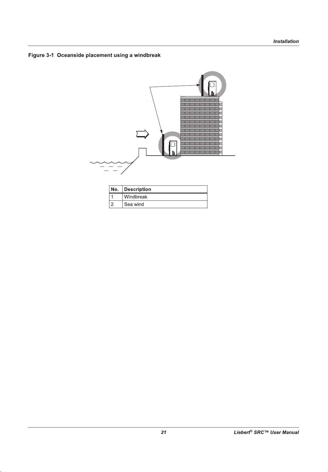
Figure 3-1: Oceanside
placement using a windbreak . . . . . . . . . . . . . . . . . . . . . . . . . . . . . . . . . . . . . . . . . . . . . . 21
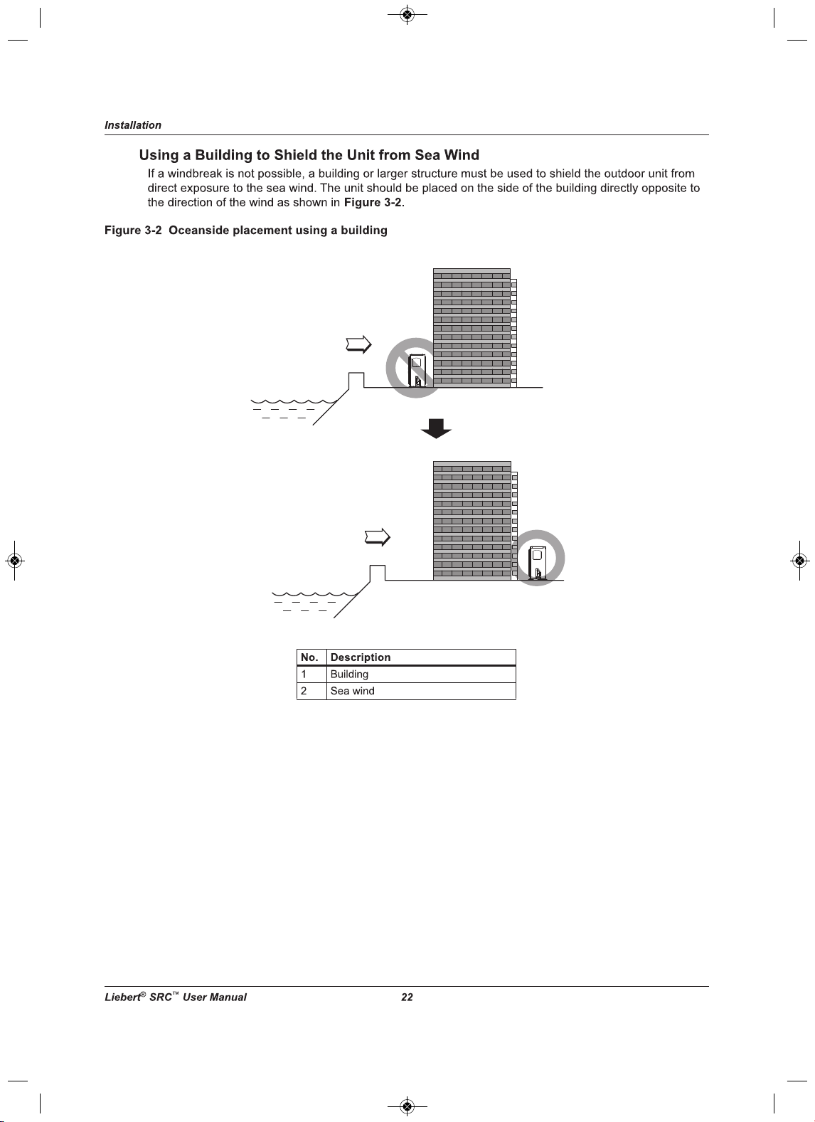
Figure 3-2: Oceanside placement using a building . . . . . . . . . . . . . . . . . . . . . . . . . . . . . . . . . . . . . . . . . . . . . . . . 22
Figure 3-3: Outdoor unit mounting methods . . . . . . . . . . . . . . . . . . . . . . . . . . . . . . . . . . . . . . . . . . . . . . . . . . . . . 23
Figure 3-4: Outdoor-unit clearances . . . . . . . . . . . . . . . . . . . . . . . . . . . . . . . . . . . . . . . . . . . . . . . . . . . . . . . . . . . 24
Figure 3-5: Outdoor-unit sunroof/awning clearances. . . . . . . . . . . . . . . . . . . . . . . . . . . . . . . . . . . . . . . . . . . . . . . 25
Figure 3-6: Clearances when there are obstacl
es on both air-inlet and air-outlet sides . . . . . . . . . . . . . . . . . . . . 25
Figure 3-7: Clearances when there are obstacles above and on both air-inlet and air-outlet sides . . . . . . . . . . . 25
Figure 3-8: Indoor unit clearance requirements . . . . . . . . . . . . . . . . . . . . . . . . . . . . . . . . . . . . . . . . . . . . . . . . . . . 26
Figure 3-9: Installation-plate
screws for SRC18. . . . . . . . . . . . . . . . . . . . . . . . . . . . . . . . . . . . . . . . . . . . . . . . . . . 27
Figure 3-10: Piping clearance for SRC18 plate . . . . . . . . . . . . . . . . . . . . . . . . . . . . . . . . . . . . . . . . . . . . . . . . . . . 27
Figure 3-11: Installation-plate screws for SRC24 and SRC36 . . . . . . . . . . . . . . . . . . . . . . . . . . . . . . . . . . . . . . . . 28
Figure 3-12: Piping clearance for SRC24 and SRC36 plate . . . . . . . . . . . . . . . . . . . . . . . . . . . . . . . . . . . . . . . . . 28
Figure 3-13: Drilling a piping hole . . . . . . . . . . . . . . . . . . . . . . . . . . . . . . . . . . . . . . . . . . . . . . . . . . . . . . . . . . . . .
29
Figure 3-14: Hook the top of the unit to the plate. . . . . . . . . . . . . . . . . . . . . . . . . . . . . . . . . . . . . . . . . . . . . . . . . . 29
Figure 3-15: Move the bottom of the unit to the plate and attach to plate . . . . . . . . . . . . . . . . . . . . . . . . . . . . . . . 30
Figure 3-16: Insert and tighten screws. . . . . . . . . . . . . . . . . . . . . . . . . . . . . . . . . . . . . . . . . . . . . . . . . . . . . . . . . . 30
Figure 3-17: Rear view of indoor unit. . . . . . . . . . . . . . . . . . . . . . . . . . . . . . . . . . . . . . . . . . . . . . . . . . . . . . . . . . . 31
Figure 5-1: Creating a flared fitting . . . . . . . . . . . . . . . . . . . . . . . . . . . . . . . . . . . . . . . . . . . . . . . . . . . . . . . . . . . . 36
Figure 5-2: Flared-connection dimensions. . . . . . . . . . . . . . . . . . . . . . . . . . . . . . . . . . . . . . . . . . . . . . . . . . . . . . . 37
Figure 5-3: Tight ening the flare nuts . . . . . . . . . . . . . . . . . . . . . . . . . . . . . . . . . . . . . . . . . . . . . . . . . . . . . . . . . . . 37
Figure 5-4: Keep piping capped while storing . . . . . . . . . . . . . . . . . . . . . . . . . . . . . . . . . . . . . . . . . . . . . . . . . . . . 38
Figure 5-5: Refrigerant-pipe brazing . . . . . . . . . . . . . . . . . . . . . . . . . . . . . . . . . . . . . . . . . . . . . . . . . . . . . . . . . . . 39
Figure 5-6: Installing piping above and bel
ow an obstacle . . . . . . . . . . . . . . . . . . . . . . . . . . . . . . . . . . . . . . . . . . 42
Figure 5-7: Coiled expansion loops and offsets . . . . . . . . . . . . . . . . . . . . . . . . . . . . . . . . . . . . . . . . . . . . . . . . . . . 44
Figure 5-8: Pipe-hanger details . . . . . . . . . . . . . . . . . . . . . . . . . . . . . . . . . . . . . . . . . . . . . . . . . . . . . . . . . . . . . . . 45
Figure 5-9: Typical pipe-support location for a change in pipe direction . . . . . . . . . . . . . . . . . . . . . . . . . . . . . . . . 46
Figure 5-10: Pipe sleeve options . . . . . . . . . . . . . . . . . . . . . . . . . . . . . . . . . . . . . . . . . . . . . . . . . . . . . . . . . . . . . . 47
Figure 5-11: Typica
l arrangement of pipe and cables in a utility conduit . . . . . . . . . . . . . . . . . . . . . . . . . . . . . . . . 48
Figure 5-12: System layout . . . . . . . . . . . . . . . . . . . . . . . . . . . . . . . . . . . . . . . . . . . . . . . . . . . . . . . . . . . . . . . . . . 49
Figure 5-13: Piping installation and connection overview . . . . . . . . . . . . . . . . . . . . . . . . . . . . . . . . . . . . . . . . . . . 50
Figure 5-14: Pipe-support spacing for outdoors. . . . . . . . . . . . . . . . . . . . . . . . . . . . . . . . . . . . . . . . . . . . . . . . . . . 50
Figure 5-15: Proper pipe and cable bundling—cut
-away. . . . . . . . . . . . . . . . . . . . . . . . . . . . . . . . . . . . . . . . . . . . 51
Figure 5-16: Bundling and taping piping and cables . . . . . . . . . . . . . . . . . . . . . . . . . . . . . . . . . . . . . . . . . . . . . . . 51
Figure 5-17: Piping/Trap when indoor unit is above outdoor unit. . . . . . . . . . . . . . . . . . . . . . . . . . . . . . . . . . . . . . 52
Figure 5-18: Piping/Trap when indoor unit is below outdoor unit . . . . . . . . . . . . . . . . . . . . . . . . . . . . . . . . . . . . . . 52
MFL67502030 17. 7. 13. 오오 3:05 Page 7

Liebert SRC
™
User Manual vi
Figure 5-19: Correct slope angle for drain hose . . . . . . . . . . . . . . . . . . . . . . . . . . . . . . . . . . . . . . . . . . . . . . . . . . 53
Figure 5-20: Incorrect methods of routing drain hose . . . . . . . . . . . . . . . . . . . . . . . . . . . . . . . . . . . . . . . . . . . . . . 53
Figure 5-21: Outdoor unit drain-connection components for SRC18 . . . . . . . . . . . . . . . . . . . . . . . . . . . . . . . . . . . 54
Figure 5-22: Outdoor unit drain-connection components for SRC24 and SRC36 . . . . . . . . . . . . . . . . . . . . . . . . . 54
Figure 5-23:
Removing connection cover from SRC18 outdoor unit . . . . . . . . . . . . . . . . . . . . . . . . . . . . . . . . . . . 55
Figure 5-24: Align center of piping connection. . . . . . . . . . . . . . . . . . . . . . . . . . . . . . . . . . . . . . . . . . . . . . . . . . . . 55
Figure 5-25: Correct piping attachment for SRC18 outdoor unit . . . . . . . . . . . . . . . . . . . . . . . . . . . . . . . . . . . . . . 56
Figure 5-26: Removing connection cover from SRC24 and SRC36 outdoor unit . . . . . . . . . . . . . . . . . . . . . . . . . 57
Figure 5-27: Align center of piping connection
. . . . . . . . . . . . . . . . . . . . . . . . . . . . . . . . . . . . . . . . . . . . . . . . . . . . 57
Figure 5-28: Correct piping attachment for SRC24 and SRC36 outdoor unit . . . . . . . . . . . . . . . . . . . . . . . . . . . . 58
Figure 5-29: Removing the chassis cover from indoor unit . . . . . . . . . . . . . . . . . . . . . . . . . . . . . . . . . . . . . . . . . . 59
Figure 5-30: Bending drain tubing at rear of indoor unit . . . . . . . . . . . . . . . . . . . . . . . . . . . . . . . . . . . . . . . . . . . . 60
Figure 5-31: Piping connection with insulation material. . . . . . . . . . . . . . . . . . . . . . . . . . . . . . . . . . . . . . . . . . . . . 60
Figure 5-32:
Correct cutting line placement . . . . . . . . . . . . . . . . . . . . . . . . . . . . . . . . . . . . . . . . . . . . . . . . . . . . . . 61
Figure 5-33: Wrapping connection pipe to indoor-unit pipe . . . . . . . . . . . . . . . . . . . . . . . . . . . . . . . . . . . . . . . . . . 61
Figure 5-34: Bundling pipe and drain hose at rear of indoor unit . . . . . . . . . . . . . . . . . . . . . . . . . . . . . . . . . . . . . . 62
Figure 5-35: Piping bundle placement in housing at rear of indoor unit. . . . . . . . . . . . . . . . . . . . . . . . . . . . . . . . . 62
Figure 5-36
: Typical pipe-insulation, power wire, and communications-cable arrangement . . . . . . . . . . . . . . . . . 63
Figure 5-37: Typical butt-joint insulation at indoor unit. . . . . . . . . . . . . . . . . . . . . . . . . . . . . . . . . . . . . . . . . . . . . . 64
Figure 5-38: Typical refrigerant flare-fitting insulation . . . . . . . . . . . . . . . . . . . . . . . . . . . . . . . . . . . . . . . . . . . . . . 64
Figure 5-39: Removing service-valve caps from outdoor unit
for purging . . . . . . . . . . . . . . . . . . . . . . . . . . . . . . . 66
Figure 5-40: Evacuation set up . . . . . . . . . . . . . . . . . . . . . . . . . . . . . . . . . . . . . . . . . . . . . . . . . . . . . . . . . . . . . . . 67
Figure 5-41: Leak-test set-up diagram. . . . . . . . . . . . . . . . . . . . . . . . . . . . . . . . . . . . . . . . . . . . . . . . . . . . . . . . . . 68
Figure 6-1: Indoor and Outdoor wiring and communications cable diagram . . . . . . . . . . . . . . . . . . . . . . . . . . . . . 72
Figure 6-2: Typical ring terminal. . . . . . . . . . . . . . . . . . . . . . . . . . . . . . . . . . . . . . . . . . . . . . . . . . . . . . . . . . . . . . . 72
Figure 6-3: Proper and Improper power-wiring connections . . . . . . . . . . . . . . . . . . . . . . . . . . . . . . . . . . . . . . . . . 73
Figure
6-4: Latch over the screws on bottom panel of indoor unit . . . . . . . . . . . . . . . . . . . . . . . . . . . . . . . . . . . . . 75
Figure 6-5: Remove screws from bottom panel . . . . . . . . . . . . . . . . . . . . . . . . . . . . . . . . . . . . . . . . . . . . . . . . . . . 76
Figure 6-6: Remove bottom panel . . . . . . . . . . . . . . . . . . . . . . . . . . . . . . . . . . . . . . . . . . . . . . . . . . . . . . . . . . . . . 76
Figure 6-7: Communication-wires knockout panel . . . . . . . . . . . . . . . . . . . . . . . . . . . . . . . . . . . . . . . . . . . . . . . . . 76
Figure 6-8: Indoor-unit terminal block with grounding cable (exampl
e only) . . . . . . . . . . . . . . . . . . . . . . . . . . . . . 77
Figure 6-9: SRC18 indoor-unit terminal-block connections . . . . . . . . . . . . . . . . . . . . . . . . . . . . . . . . . . . . . . . . . . 77
Figure 6-10: SRC24 and SRC36 indoor unit terminal-block connections . . . . . . . . . . . . . . . . . . . . . . . . . . . . . . . 78
Figure 6-11: SRC18 outdoor-unit terminal-block connections . . . . . . . . . . . . . . . . . . . . . . . . . . . . . . . . . . . . . . . . 79
Figure 6-12: SRC24 and SRC36 outdoor-unit terminal-block connections
. . . . . . . . . . . . . . . . . . . . . . . . . . . . . . 80
Figure 6-13: Circuit breaker wiring. . . . . . . . . . . . . . . . . . . . . . . . . . . . . . . . . . . . . . . . . . . . . . . . . . . . . . . . . . . . . 80
Figure 6-14: Proper and Improper thermostat locations . . . . . . . . . . . . . . . . . . . . . . . . . . . . . . . . . . . . .
. . . . . . . 81
Figure 6-15: Cable-entry hole/guide grooves. . . . . . . . . . . . . . . . . . . . . . . . . . . . . . . . . . . . . . . . . . . . . . . . . . . . . 82
Figure 6-16: Thermostat back plate installation . . . . . . . . . . . . . . . . . . . . . . . . . . . . . . . . . . . . . . . . . . . . . . . . . . . 82
Figure 6-17: Mounting thermostat onto back plate . . . . . . . . . . . . . . . . . . . . . . . . . . . . . . . . . . . . . . . . . . . . . . . . 83
Figure 6
-18: Extension cable from indoor unit to thermostat . . . . . . . . . . . . . . . . . . . . . . . . . . . . . . . . . . . . . . . . . 83
Figure 6-19: Thermostat cable prep. . . . . . . . . . . . . . . . . . . . . . . . . . . . . . . . . . . . . . . . . . . . . . . . . . . . . . . . . . . . 84
Figure 6-20: Thermostat and Indoor unit terminal-block connections . . . . . . . . . . . . . . . . . . . . . . . . . . . . . . . . . . 84
MFL67502030 17. 7. 13. 오오 3:05 Page 8

vii Liebert SRC
™
User Manual
Figure 8-1: On/Off button location . . . . . . . . . . . . . . . . . . . . . . . . . . . . . . . . . . . . . . . . . . . . . . . . . . . . . . . . . . . . . 91
Figure 9-1: Cleaning the outside of the indoor unit . . . . . . . . . . . . . . . . . . . . . . . . . . . . . . . . . . . . . . . . . . . . . . . 101
Figure 9-2: Removing the air filter from Type 1 unit . . . . . . . . . . . . . . . . . . . . . . . . . . . . . . . . . . . . . . . . . . . . . . . 102
Figure 9-3: Inserting cleaned air filter in Type 1 unit . . . . . . . . . . . . . . . . . . . . . . . . . . . . . . . . . . . . . . . . . . . . . . 102
Figure 9-4: K
nobs on air filter of Type 2 unit . . . . . . . . . . . . . . . . . . . . . . . . . . . . . . . . . . . . . . . . . . . . . . . . . . . . 102
Figure 9-5: Removing the air filter from Type 2 unit . . . . . . . . . . . . . . . . . . . . . . . . . . . . . . . . . . . . . . . . . . . . . . . 103
Figure 9-6: Inserting cleaned air filter on the hooks of the Type 2 unit . . . . . . . . . . . . . . . . . . . . . . . . . . . . . . . . 103
Figure 9-7: Push down on
the hooks of the Type 2 unit. . . . . . . . . . . . . . . . . . . . . . . . . . . . . . . . . . . . . . . . . . . . 103
Figure 9-8: Removing 3M/Triple filters from indoor unit . . . . . . . . . . . . . . . . . . . . . . . . . . . . . . . . . . . . . . . . . . . . 104
Figure 9-9: Replacing 3M/Triple filters in the indoor unit . . . . . . . . . . . . . . . . . . . . . . . . . . . . . . . . . . . . . . . . . . . 104
Figure 10-1: Error codes displayed at the thermostat . . . . . . . . . . . . . . . . . . . . . . . . . . . . . . . . . . . . . . . . . . . . . 106
Figure
10-2: Error-code display for SRC18 . . . . . . . . . . . . . . . . . . . . . . . . . . . . . . . . . . . . . . . . . . . . . . . . . . . . . 107
Figure 10-3: Error-code display for SRC24 and SRC36 . . . . . . . . . . . . . . . . . . . . . . . . . . . . . . . . . . . . . . . . . . . 107
Figure 10-4: Refrigerant Concentration Limit (RCL) Calculations Equation. . . . . . . . . . . . . . . . . . . . . . . . . . . . . 111
MFL67502030 17. 7. 13. 오오 3:05 Page 9

Liebert SRC
™
User Manual viii
List of Tables
Tab le 2-1: Indoor unit electrical data . . . . . . . . . . . . . . . . . . . . . . . . . . . . . . . . . . . . . . . . . . . . . . . . . . . . . . . . . . . 16
Tab le 5-1: Flared-connection dimensions . . . . . . . . . . . . . . . . . . . . . . . . . . . . . . . . . . . . . . . . . . . . . . . . . . . . . . . 37
Tab le 5-2: Tightening torque for flare nuts . . . . . . . . . . . . . . . . . . . . . . . . . . . . . . . . . . . . . . . . . . . . . . . . . . . . . . . 37
Tab le 5-3: Three principles of refrigerant piping. . . . . . . . . . . . . . . . . . . . . . . . . . . . . . . . . . . . . . . . . . . . . . . . . . . 38
Tab le 5-4: ACR copper-tubing material . . . . . . . . . . . . . . . . . . . . . . . . . . . . . . . . . . . . . . . . . . . . . . . . . . . . . . . . . 40
Tab le 5-5: Piping-
tube thickness . . . . . . . . . . . . . . . . . . . . . . . . . . . . . . . . . . . . . . . . . . . . . . . . . . . . . . . . . . . . . . 41
Tab le 5-6: ACR copper-tubing dimensions and physical characteristics . . . . . . . . . . . . . . . . . . . . . . . . . . . . . . . . 41
Tab le 5-7: Linear thermal expansion of copper tubing, in inches . . . . . . . . . . . . . . . . . . . . . . . . . . . . . . . . . . . . . . 43
Tab le 5-8: Radii of coiled expansion loops and developed lengths of expansion offsets. . . . . . . . . . . . . . . . . . . . 44
Tab le 5-9: Equival
ent piping length for piping components . . . . . . . . . . . . . . . . . . . . . . . . . . . . . . . . . . . . . . . . . . 45
Tab le 5-10: Utility-conduit sizes . . . . . . . . . . . . . . . . . . . . . . . . . . . . . . . . . . . . . . . . . . . . . . . . . . . . . . . . . . . . . . . 48
Tab le 5-11: Heat-pump unit refrigerant-pipe connections (All brazed type) . . . . . . . . . . . . . . . . . . . . . . . . . . . . . . 48
Tab le 5-12: Refrigerant-piping system limitations . . . . . . . . . . . . . . . . . . . . . . . . . . . . . . . . . . . . . . . . . . . . . . . . . 49
Tab le 5-13: Outdoor unit drain-connection components . . . . . . . . . . . . . . . . . . . . . . . . . . . . . . . . . . . . . . . . . . . . 54
Tab le
5-14: Tightening torque for flare nuts . . . . . . . . . . . . . . . . . . . . . . . . . . . . . . . . . . . . . . . . . . . . . . . . . . . . . . 56
Tab le 5-15: Tightening torque for flare nuts . . . . . . . . . . . . . . . . . . . . . . . . . . . . . . . . . . . . . . . . . . . . . . . . . . . . . . 58
Tab le 5-16: Insulation guidelines for typical and special circumstances . . . . . . . . . . . . . . . . . . . . . . . . . . . . . . . . 65
Tab le 5-17: Evacuation timing* . . . . . . . . . . . . . . . . . . . . . . . . . . . . . . . . . . . . . . . . . . . . . . . . . . . . . . . . . . . . . . . 69
Tab le 7-1: General unit functions—Installer set
-up codes . . . . . . . . . . . . . . . . . . . . . . . . . . . . . . . . . . . . . . . . . . . 85
Tab le 7-2: Thermistor setting options . . . . . . . . . . . . . . . . . . . . . . . . . . . . . . . . . . . . . . . . . . . . . . . . . . . . . . . . . . . 88
Tab le 7-3: Ceiling-height setting options . . . . . . . . . . . . . . . . . . . . . . . . . . . . . . . . . . . . . . . . . . . . . . . . . . . . . . . . 89
Tab le 9-1: Cleaning Schedule . . . . . . . . . . . . . . . . . . . . . . . . . . . . . . . . . . . . . . . . . . . . . . . . . . . . . . . . . . . . . . . 101
Tab le 10-1: Error Codes. . . . . . . . . . . . . . . . . . . . . . . . . . . . . . . . . . . . . . . . . . . . . . . . . . . . . . . . . . . . . . . . . . . . 108
Tab le 10-2: Troubleshooting problems, causes and correction . . . . . . . . . . . . . . . . . . . . . . . . . . . . . . . . . . . . . . 109
MFL67502030 17. 7. 13. 오오 3:05 Page 10
Important Safety Instructions
1Liebert
®
SRC™ User Manual
Important Safety Instructions
SAVE THESE INSTRUCTIONS
Do not throw away, destroy or lose this manual. Please read carefully and store in a safe place for future
reference. Content familiarity required for proper installation.
The instructions included in this manual must be followed to prevent product malfunction, property
damage, injur
y, or death to the user or other people. Incorrect operation due to ignoring any instructions
will cause harm or damage.
For more technical materials such as submittals, engineering databooks and catalogs,
visit www.liebert.com.
!
WARNING
Risk of improper unit installation and/or removal. Can cause water and/or refrigerant leakage,
electric shock, smoke, fire and explosion resulting in building and equipment damage, serious
injury or death. Do not install, remove, or re-install the unit by yourself (customer)
. Ask the dealer
or an authorized technician to install the unit. For replacement of an installed unit, always contact
an authorized Liebert service provider.
!
WARNING
Risk of explosive discharge of high pressure gas. Can cause serious injury. The unit is shipped
with refrigerant and the service valves closed. Do not open service valves on the unit until all non-
condensibles have been removed from the piping system and authorization to
do so has been
obtained from the commissioning agent.
!
WARNING
Risk of excessive refrigerant pressure. Can cause equipment damage, serious injury or death. Do
not run the compressor with the service valves closed.
!
WARNING
Arc flash and electric shock hazard. Can cause serious injury or death. Open all local and remote
electric power disconnect switches, verify with a voltmeter that power is off and wear personal
protective equipment per NFPA 70E before working within the electric control enclosure
. All
electric work must be performed by a licensed electrician and conform to all applicable national,
state and local electrical codes Replace and securely fasten all control box and panel covers
immediately after working on the unit to protect the operator from
the hazards above and prevent
the intrusion of dust, water and animals that may cause additional hazards to develop.
!
WARNING
Risk of contact with sharp edges, nails, splinters, and other packaging materials and improper
disposal of plastic bags. Can cause injury or death. Wear gloves and arm protection when
unpacking the unit and and Dispose the packing materials safely.
Cut the p
lastic packaging bag into small pieces or dispose of securely to eliminate the risk of
suffocation and death from improperly wearing the plastic bag as a head cover.
MFL67502030 17. 7. 13. 오오 3:05 Page 11
Important Safety Instructions
3Liebert
®
SRC™ User Manual
!
WARNING
Risk of electric shock. Can cause injury or death. Secure all hazardous voltage field wiring
connections with appropriate wire strain relief.
Improperly secured wires will create excessive stress on electric al power connection lugs.
Improper or loose connections may generate excessive heat and cause smoke
and fire.
!
WARNING
Risk of damaged electrical components and short circuits. Can cause building and equipment
damage, smoke, fire, injury and death. Do not provide power to or operate the unit if it is flooded or
submerged.
!
WARNING
Use a dedicated power source for this product.
There is risk of fire, electric shock, physical injury or death.
!
WARNING
Risk of unit mounting base deterioration and collapse. Can cause building and equipment
damage, injury or death. Periodically verify the equipment mounts have not deteriorated.
!
WARNING
Risk of electric shock and contact with high speed moving parts. Can cause serious injury or
death. Do not operate the unit with the panel(s) or protective cover(s) removed; keep fingers and
clothing away from moving parts. Do not open the inlet grille of the unit
during operation. Do not
insert hands or other objects through the inlet or outlet when the unit is plugged in. Do not touch
the electrostatic filter, if the unit includes one.
!
WARNING
Risk of electric shock. Can cause injury or death. Periodically, check power cord and plug for
damage. Damaged power cords must be replaced by the manufacturer, its service agent, or
similar Liebert-trained and qualified persons.
!
CAUTION
Risk of exposure to refrigerant gas. Can cause injury or illness. Always check for system
refrigerant leaks after the unit has been installed or serviced.
!
CAUTION
Risk of contact with sharp edges. Can cause injury. Wear protective gloves when handling
equipment.
MFL67502030 17. 7. 13. 오오 3:05 Page 13
Important Safety Instructions
Liebert
®
SRC
™
User Manual 4
NOTICE
Risk of exposure to corrosive environments. Can cause equipment damage. Don’t install the unit
where it’s directly exposed to ocean winds.
Ocean winds may cause corrosion, particularly on the condenser and evaporator fins, which, in
turn could cause product malfunction or inefficient performance.
NOTICE
Risk of water damage and abnormal vibration. Can cause equipment damage
When installing the unit in a low-lying area, or a location that is not level, use a raised concrete pad
or concrete blocks to provide a solid, level foundation.
NOTICE
Risk of excessive condenastion. Can cause building and equipment damage.
Properly insulate all cold surfaces to prevent “sweating.” Cold surfaces such as uninsulated piping
can generate condensate that may drip and cause a slippery floor condition and/or water damage
to walls.
!
CAUTION
Risk of exposure to excessive refrigerant concentration and oxygen depletion. Can cause illness
or injury. If the unit is installed in a small improperly or non-ventilated space, take measures to
prevent the refrigerant concentration from exceeding safety limits in the event of a refrigerant
leak.
Consult the latest edition of ASHRAE (American Society of Heating, Refrigerating, and Air
Conditioning Engineers) Standard 15.
!
CAUTION
Risk of contact with extremely hot and cold surfaces. Can cause injury. Refrigerant piping is
extremely hot or cold during unit operation. Do not touch the refrigerant piping during or after
operation. Wear thermally insulated gloves and arm protection or allow the piping to cool or
warm
to a safe handling temperature before working on the piping.
!
CAUTION
Risk of improper lifting and moving of a heavy unit. Can cause building and equipment damage
and injury. Be very careful when transporting the product.
• Do not attempt to carry the product without assistance. Some products use polypropylene
bands for packaging. Do not use polypropyl
ene bands to lift the unit.
• Suspend the unit from the base at specified positions.
• Support the unit a minimum of four points to avoid slippage from rigging apparatus.
Verify that all lifting apparatus is rated for the weight of the unit. See XREF TABLE for indoor and
outdoor
unit weights.
!
CAUTION
Risk of contact with sharp edges, and extremely hot or cold components. Can cause injury. Wear
OSHA approved head and eye protection, thermally insulated gloves and arm protection or allow
the unit to reach a safe for contact temperature and use caution when cleaning
or servicing the
unit.
MFL67502030 17. 7. 13. 오오 3:05 Page 14

Important Safety Instructions
5Liebert
®
SRC™ User Manual
NOTICE
Risk of exposure to excessive Electro-Magnetic Interference. Can cause equipment malfunction.
When installing the unit in a hospital, mechanical room, or similar electromagnetic field (EMF)
sensitive environment, provide sufficient protection against electrical noise.
Inverter equipment, power generators, high-frequency medical
equipment, or radio communication
equipment may cause the unit to operate improperly. The unit may also affect such equipment by
creating electrical noise that disturbs medical treatment or image broadcasting.
NOTICE
Risk of using the wrong refrigerant. Can cause equipment damage
Do not make refrigerant substitutions. Use R410A only.
If a different refrigerant is used, or air mixes with original refrigerant, the unit will malfunction and
be damaged.
NOTICE
Risk of excessive vibration and water leakage. Can cause building and equipment damage
Keep the unit upright during installation to avoid compressor, piping and component damage.
NOTICE
Risk of improper refrigerant piping practices. Can cause refrigerant leaks resulting in building and
equipment damage
When connecting refrigerant tubing, remember to allow for pipe expansion. Improper piping may
cause refrigerant leaks and system malfunction.
NOTICE
Risk of an improper installation location. Can cause equipment damage
Install the unit in a safe location where nobody can step on or fall onto it. Do not install the unit on
a defective stand. Periodically check that the outdoor frame is not damaged
NOTICE
Risk of leaking water. Can cause building and equipment damage.
Install the drain hose as specified in this manual to ensure adequate drainage and periodically
check for damage, obstruction and leaks.
NOTICE
Risk of leaking refrigerant. Can cause equipment malfunction and damage.
Always check for system refrigerant leaks after the unit has been installed or serviced. Low
refrigerant levels may cause product failure.
NOTICE
Risk of cold compressor at startup. Can cause equipment damage.
Provide power to the compressor crankcase heaters at least six (6) hours before operation begins.
Starting operation with a cold compressor sump(s) may result in severe bearing damage to the
compressor(s). Keep the power switch on during
the operational season.
MFL67502030 17. 7. 13. 오오 3:05 Page 15
Important Safety Instructions
Liebert
®
SRC
™
User Manual 6
NOTICE
Risk of blocked inlet and outlet air vents. Can cause equipment malfunction and damage. Do not
block the inlet or outlet. Unit may malfunction.
NOTE
Do not install the unit in a noise sensitive area.
NOTE
Take appropriate actions at the end of HVAC equipment life to recover,
recycle, reclaim or destroy R410A refrigerant according to applicable U.S.
Environmental Protection Agency (EPA) rules.
NOTE
Don’t store or use flammable gas / combustibles near the unit. There is risk of
product failure.
NOTE
Clean up the site after installation is finished, and check that no metal scraps,
screws, or bits of wiring have been left inside or surrounding the unit.
NOTE
Do not use this equipment in mission critical or special purpose applications
such as preserving foods, works of art, wine coolers or refrigeration. The
equipment is designed to provide cooling and heating for electronic and
telecommunications equipment.
Oil, steam, sulfuric smoke, etc., can significantly reduce the performance of
the unit, or damage its parts.
NOTE
• If the leaking battery fluid has been swallowed, wash off the inside of the
mouth thoroughly and consult a doctor.
• Do not drink the water drained from the unit.
• Do not use the product for special purposes, such as preserving foods,
works of art, and etc. It is an unit for consumer purposes, not a precision
refrigeration system. There is risk of damage or loss of property.
• Do not recharge or disassemble the batteries.
NOTE
Maintenance
• Never touch the metal parts of the unit when removing the air filter.
• Use a sturdy stool or ladder when cleaning, maintaining, or repairing the
unit at a height.
• Never use strong cleaning agents or solvents when cleaning the unit or
spray water.
• Use a smooth cloth.
MFL67502030 17. 7. 13. 오오 3:05 Page 16
Safety Symbols
7Liebert
®
SRC™ User Manual
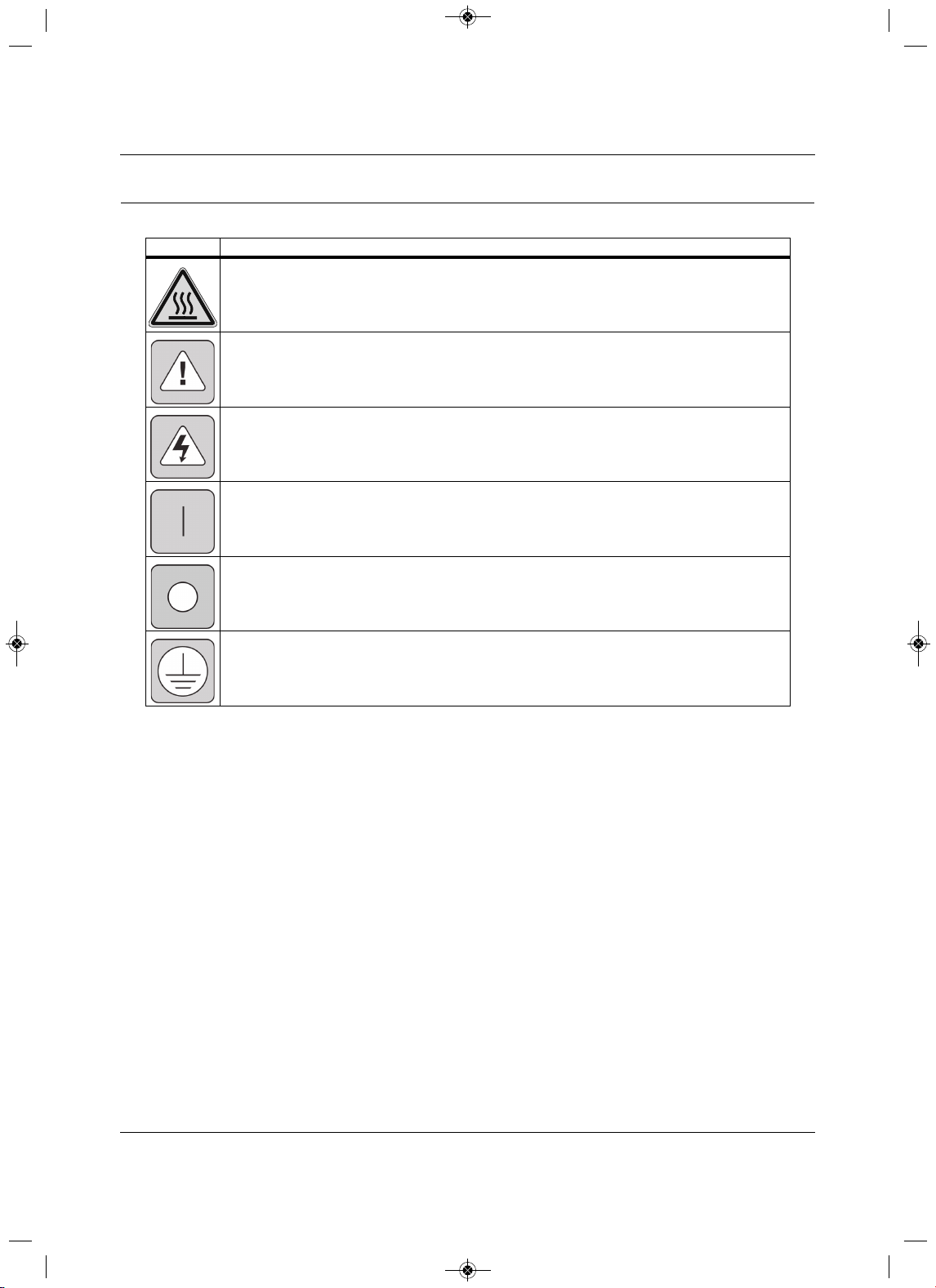
Safety Symbols
The following symbols may appear within the documentation or on the product.
Symbol Meaning
High Temperature
Alerts the user where the enclosure temperature may exceed 158°F (70°C) while operating under high-
ambient temperature and at maximally rated load.
Instructions
Signifies the presence of important operating and maintenance (servicing) instructions in the literature
accompanying the appliance.
Dangerous Voltage
Warns about the presence of uninsulated dangerous voltage within the product’s enclosure that may be
of sufficient magnitude to constitute a risk of electric shock to persons.
Power On
Indicates the principal On/Off switch is in the On position.
Power Off
Indicates the
principal On/Off switch is in the Off position.
Protective Grounding Terminal
Indicates a terminal that must be connected to earth ground before any other connections to the
equipment may be made.
MFL67502030 17. 7. 13. 오오 3:05 Page 17

Safety Symbols
Liebert
®
SRC
™
User Manual 8
Page intentionally left blank.
MFL67502030 17. 7. 13. 오오 3:05 Page 18
Model Number and Nomenclature
9Liebert
®
SRC™ User Manual
1.0 Model Number and Nomenclature
Figure 1-1 Product Nomenclature
H
0
0N
AHRI Type
H = Heat pump
Placeholder
Nominal Capacity (in Btu/h)
12 = 12,000
18 = 18,000
24 = 24,000
36 = 36,000
Revision
Example: SRC24 HPN000
P
Voltage
P = 208 – 230/1/60
24
Unit Type
N = Indoor evaporator
C = Outdoor condensing unit
0
Placeholder
SRC
MFL67502030 17. 7. 13. 오오 3:05 Page 19

Model Number and Nomenclature
Liebert
®
SRC
™
User Manual 10
Page intentionally left blank.
MFL67502030 17. 7. 13. 오오 3:05 Page 20
Product Introduction
11 Liebert
®
SRC™ User Manual
2.0 Product Introduction
Suggestions for Energy Saving when Operating the Liebert SR C:
• Do not cool excessively indoors. This may be harmful for your health and may consume more
electricity.
• Block sunlight with blinds or curtains while you are operating the unit.
•Keep doors or windows closed tightly while you are operating the unit.
• Adjust the direction of the air flow vertically or horizontally to circulate indoor air.
• Speed up the fan to cool or warm indoor air quickly, within a short period of
time.
• Open windows regularly for ventilation. The indoor air quality may deteriorate if the unit is used for long
durations.
• Clean the air filter once every 2 weeks. Dust and impurities collected in the air filter may block
the air
flow or weaken the cooling / dehumidifying functions.
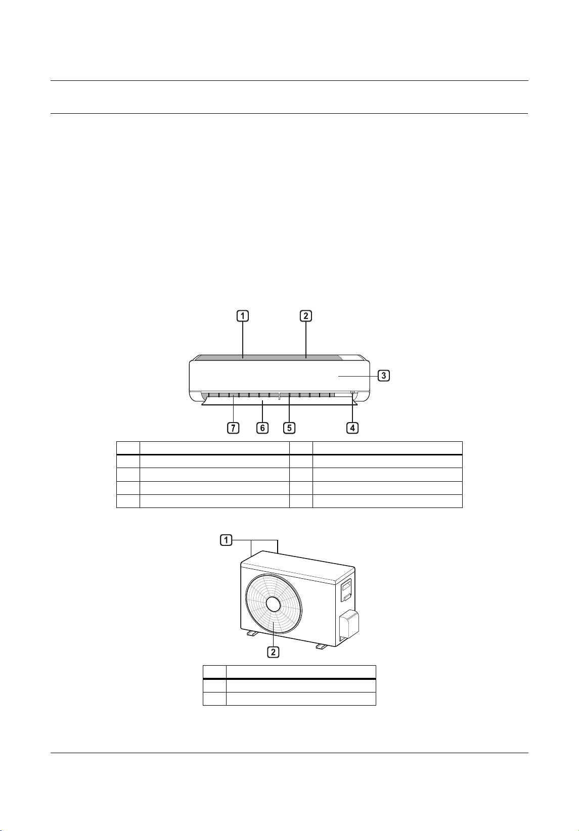
Figure 2-1 Indoor Unit Parts and Functions
Figure 2-2 Outdoor Unit Parts and Functions
No.Description No.Description
1 Air filter (under the panel)5Air deflector (vertical louver)
2 Air intake6Air deflector (horizontal vane)
3 Front cover 7 Air outlet
4 On/Off button
No.Description
1 Air intake vents
2 Air outlet vents
MFL67502030 17. 7. 13. 오오 3:05 Page 21
Product Introduction
Liebert
®
SRC
™
User Manual 12
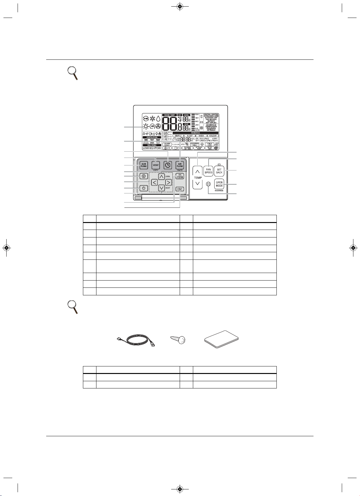
Figure 2-3 Thermostat parts and functions
Figure 2-4 Accessories
NOTE
The number and location of operation lamps may vary by unit model.
The features may vary by model.
No.Description No.Description
1Operation indication 10 Air-flow button
2Set temperature button 11 Cooling temperature setpoint
3 Fan speed button 12 Function setting button
4 Set back button 13 Up, down, left and right buttons
5 Operation-mode select button 14 On/Off button
6
Wireless thermostat receiver
(not included on some models)
15 Heating temperature setpoint
7Sub
function button 16 Set/Cancel button
8 Ventilation button 17 Exit button
9 Reservation button
NOTE
Some functions may not be available or displayed depending on unit type.
No.Description No.Description
1 Connection cable, 1 each, 32 ft (10 m) 3 User Manual
2 Screw, 4 each
1
7
8
9
10
11
13
12
14
15
16
17
2
3
4
5
6
Connection Cable
(1EA, 3 2ft (10m))
Screw
(4 EA)
Installation & Operation
Manual
MFL67502030 17. 7. 13. 오오 3:05 Page 22
Product Introduction
13 Liebert
®
SRC™ User Manual
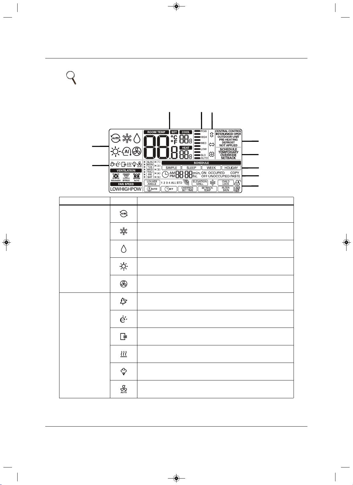
Figure 2-5 Icon descriptions and functions
NOTE
Some options and functions may not be displayed or the menu name may be
different depending on your system and model.
Section Icon Description
1 Operating Mode
Auto—change to cooling or heating mode automatically.
Operating in cooling mode.
Operating in dehumidification mode.
Operating in heating mode.
Operating in fan-only mode.
2 Sub functions
Plasma purification filter is operating.
Energy-saving cooling mode, operating in limited temperature
range.
Automatic drying is operating.
Electric heater is operating in heater mode.
Humidifier is operating.
Automatic fan function on indoor unit.
The fan doesn’t operate in the indoor unit when the compressor is off.
1
2
345
6
7
8
9
10
MFL67502030 17. 7. 13. 오오 3:05 Page 23
Product Introduction
Liebert
®
SRC
™
User Manual 14
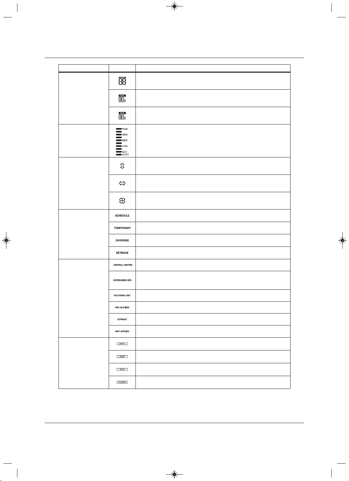
3 Temperature
Current temperature.
Cooling temperature setpoint.
Heating temperature setpoint.
4 Fan Speed Fan-speed settings.
5 Air-flow/Louvers
Swing louvers up/down.
Swing louvers left/right.
Swing louvers for “swirl” (paired, opened cross swing).
6 Controller Modes
Operate in schedule mode.
Temporarily operate in a
mode.
Override schedule (occupied/unoccupied).
Operate in set-back mode.
7 State Monitoring
Command received from central controller or outdoor unit.
Slave indoor unit to a heat-pump system.
Prevents changing to a mode that is incompatible with the current mode of
the outdoor unit.
Outdoor unit
is operating.
Indoor unit is pre-heating.
Defrost is operating.
Function is not applied.
8 Schedule
Simple schedule is in use.
Sleep schedule is in use.
Weekly schedule is in use.
Holiday schedule is in use.
Section Icon D
escription
MFL67502030 17. 7. 13. 오오 3:05 Page 24
Product Introduction
15 Liebert
®
SRC™ User Manual
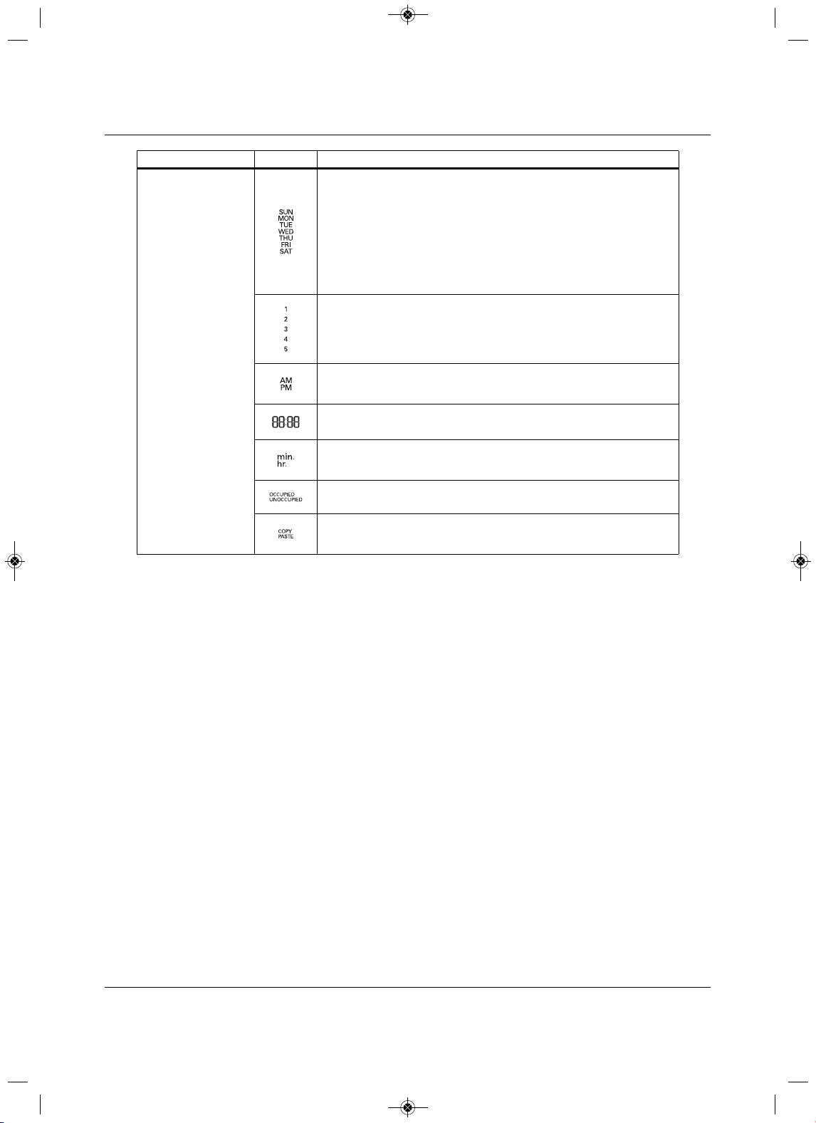
9 Schedule Set-up
Day of Week:
•SUN = Sunday
•MON = Monday
•TUE = Tuesday
•WED = Wednesday
•THU = Thursday
• FRI = Friday
•SAT = Saturday
Number of the weekly-schedule event.
Schedule time AM/PM.
Schedule time hour/minute.
min. = minute.
hr. = hour.
Weekly schedule occupied/un-occupied state.
Copy/Paste
schedule data.
Section Icon Description
MFL67502030 17. 7. 13. 오오 3:05 Page 25
Product Introduction
Liebert
®
SRC
™
User Manual 16
2.1 Electrical Data
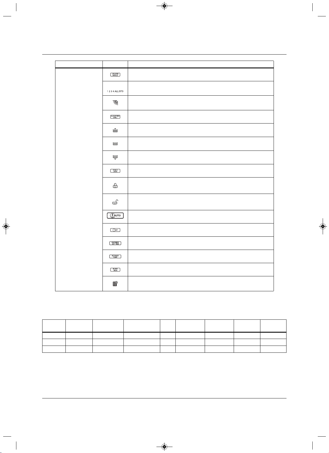
10 Function Settings
Louver set-up.
1, 2, 3, 4, All = louver number.
STD = standard louver angle setting.
Angle of the louver.
Elevation grill set-up.
Grill up.
Grill closed.
Grill down.
Display lock set-up
Display is locked.
Display is not locked.
Set-up
minimum-difference value between cooling and heating setpoints.
Set current time.
Set timer for schedule override.
Set-up default setback for cooling/heating temperature setpoints.
Clear the air-filter cleaning alarm.
Check the indoor-unit air filter and clean
if necessary.
Table 2-1 Indoor unit electrical data
ModelNom. Tons
Compressor
Qty.
Compressor ( A)
Cool/Heat
Fan
Qty. ODU Fan (A) IDU Fan (A) MCA (A) MOP (A)
SRC18 1-1/21 14.6/14.61 0.25 0.401925
SRC24 1-3/4 117.3/17.31 0.25 0.52335
SRC36 2-3/4 117.3/17.31 0.25 0.52335
Section Icon Description
MFL67502030 17. 7. 13. 오오 3:05 Page 26
Product Introduction
17 Liebert
®
SRC™ User Manual
2.2 R410A Refrigerant
R410A refrigerant has a higher operating pressure in comparison to R22 refrigerant and, therefore, all
piping-system materials installed must have a higher resisting pressure that the materials traditionally used
in R22 systems.
R410A refrigerant is an azeotrop of R32 and
R125, mixed at 50:50, so the ozone depletion potential (ODP)
is zero. Many countries have approved-of and encouraged R410A for use as an alternate refrigerant.
!
WARNING
Risk of piping ruptures and refrigerant leaks. Can cause equipment damage, illness, serious injury
and death from suffocation. Do not use piping that is not approved for use in high-pressure
refrigerant systems. Refrigerant leaks in non-ventilated spaces could cause
oxygen depletion
levels that are dangerous to humans. Follow accepted safety practices for refrigerant storage,
discharging and charging.
NOTE
• Piping wall thickness must comply with the applicable local, state, and
federal codes for the 551-psi design pressure of R410A.
• Because R410A is a combination of R32 and R125, the required additional
refrigerant must be charged in its liquid state. If the refrigerant is charged in
its gaseous state, its composition changes and the system will not work
properly.
MFL67502030 17. 7. 13. 오오 3:05 Page 27

Product Introduction
Liebert
®
SRC
™
User Manual 18
Page intentionally left blank.
MFL67502030 17. 7. 13. 오오 3:05 Page 28
Installation
19 Liebert
®
SRC™ User Manual
3.0 Installation
3.1Selecting the Location for the Outdoor Unit
NOTICE
Risk of unauthorized access to the unit. Can cause equipment malfunction or damage.
Install a fence to prevent vermin from crawling into the unit or unauthorized individuals from
accessing it.
Select a location for installing the outdoor unit that
will meet the following conditions:
• Where the unit will not be subjected to direct thermal radiation from other heat sources.
• Where operating sound from the unit will not disturb inhabitants of surrounding buildings.
• Where the unit will not be exposed to direct, strong
winds.
• Where there is enough strength to bear the weight of the unit.
•Include space for drainage to ensure condensate flows properly out of the unit when it is in
heating mode.
•Include enough space for air flow and for service access.
To
ensure that the outdoor unit operates properly, certain measures are required in locations where there is
a possibility of heavy snowfall or severe wind chill or cold.
1. Prepare for severe winter wind chills and heavy snowfall, even in areas of
the country where these are
unusual phenomena.
2. Position the outdoor unit so that its airflow fans are not buried by direct, heave snowfall. If snow piles
up and blocks the airflow, the system may malfunction.
3. Remove any snow that
has accumulated 3-15/16 inches or more on the top of the outdoor unit .
4. Place the outdoor unit on a raised platform at least 19-11/16 inches higher than the average annual
snowfall for the area. In environments where there is a possibi
lity of heavy snow, the frame height
must be more than 2 times the amount of average annual snowfall, and should not exceed the width of
the outdoor unit. If the frame width is wider than the outdoor unit, snow may accumulate.
5.Install a
snow-protection hood.
!
WARNING
Risk of improper installation. Can cause serious injury or death.
• To avoid the possibility of fire, do not install the unit in an area where combustible gas may
generate, flow, stagnate, or leak.
• Do not install the unit in a location where acidic
solution and spray (sulfur) are often used as it
can cause bodily injury or death.
• Do not use the unit in environments where oil, steam, or sulfuric gas are present as it can cause
bodily injury or death.
MFL67502030 17. 7. 13. 오오 3:05 Page 29
Installation
Liebert
®
SRC
™
User Manual 20
6. To prevent snow and heavy rain from entering the outdoor unit, install the suction and discharge ducts
facing away from direct winds.
7. Additionally6, the following conditions should be taken into consideration when the unit operates in
defrost mode:
•If the outdoor
unit is installed in a highly-humid environment (near an ocean, lake, etc.), ensure
that the site is well-ventilated and has a lot of natural light. (For example: Install on a rooftop.)
• Sidewalks or parking lots near
the outdoor unit may accumulate moisture after unit operates in
defrost mode that can turn into ice.
Installation location of the outdoor unit can affect indoor-unit operation. The indoor unit may take longer to
provide heat, or heating performance will be reduced in winter
in the outdoor unit is installed:
•In a narrow, shady location.
•Near a location that has a lot of ground moisture.
•In a highly-humid environment.
•In an area in which condensate does not drain properly.
3.1.1 Ambient air conditions
NOTICE
Risk of exposure to improper environmental conditions. Can cause equipment damage.
• Avoid exposing the outdoor unit to steam, combustible gases, or other corrosive elements.
• Avoid exposing the unit to discharge from boiler stacks, chimneys, steam relief
ports, other air-
conditioning units, kitchen vents, plumbing vents, or substances that may degrade performance
or cause damage to the unit.
• When installing multiple outdoor units, avoid placing the units where discharge of one outdoor
unit will blow into the inlet
side of an adjacent unit.
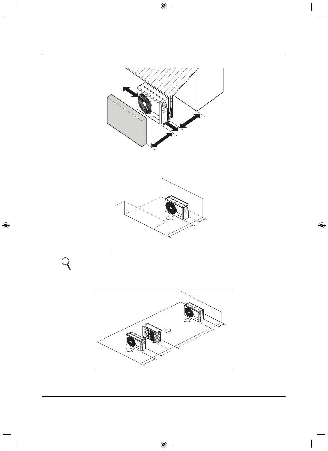
3.1.2 Oceanside Applications
Using a Windbreak to Shield the Unit from Sea Wind
• Avoid installing the unit where it would be directly exposed to ocean w inds.
•Install the outdoor unit on the side of the building opposite from direct ocean winds.
• Select a location with good drainage.
• Periodically clean dust or salt particles off of the heat exchanger with water.
•If the outdoor unit must be placed in a location where it would be subjected to direct ocean winds,
install a concrete windbreak strong enough to block any winds, see Figure 3-1 for windbreak location.
• T
he windbreak should be more than 150% of the outdoor unit’s height. There must be 2 to 3-1/2 inches
of clearance between the outdoor unit and the windbreak for purposes of flow.
NOTE
Ocean winds may cause corrosion, particularly on the condenser and
evaporator fins, which, in turn could cause product malfunction or inefficient
performance.
MFL67502030 17. 7. 13. 오오 3:05 Page 30
2
1
MFL67502030 17. 7. 13. 오오 3:05 Page 31
2
1
2
1
MFL67502030 17. 7. 13. 오오 3:05 Page 32
Installation
23 Liebert
®
SRC™ User Manual
3.2Mounting the Outdoor Unit
Securely attach the outdoor unit to a condenser pad, base rails, or another mounting platform that is
securely anchored to the ground or building structure. Attach the outdoor unit with a bolt and nut on a
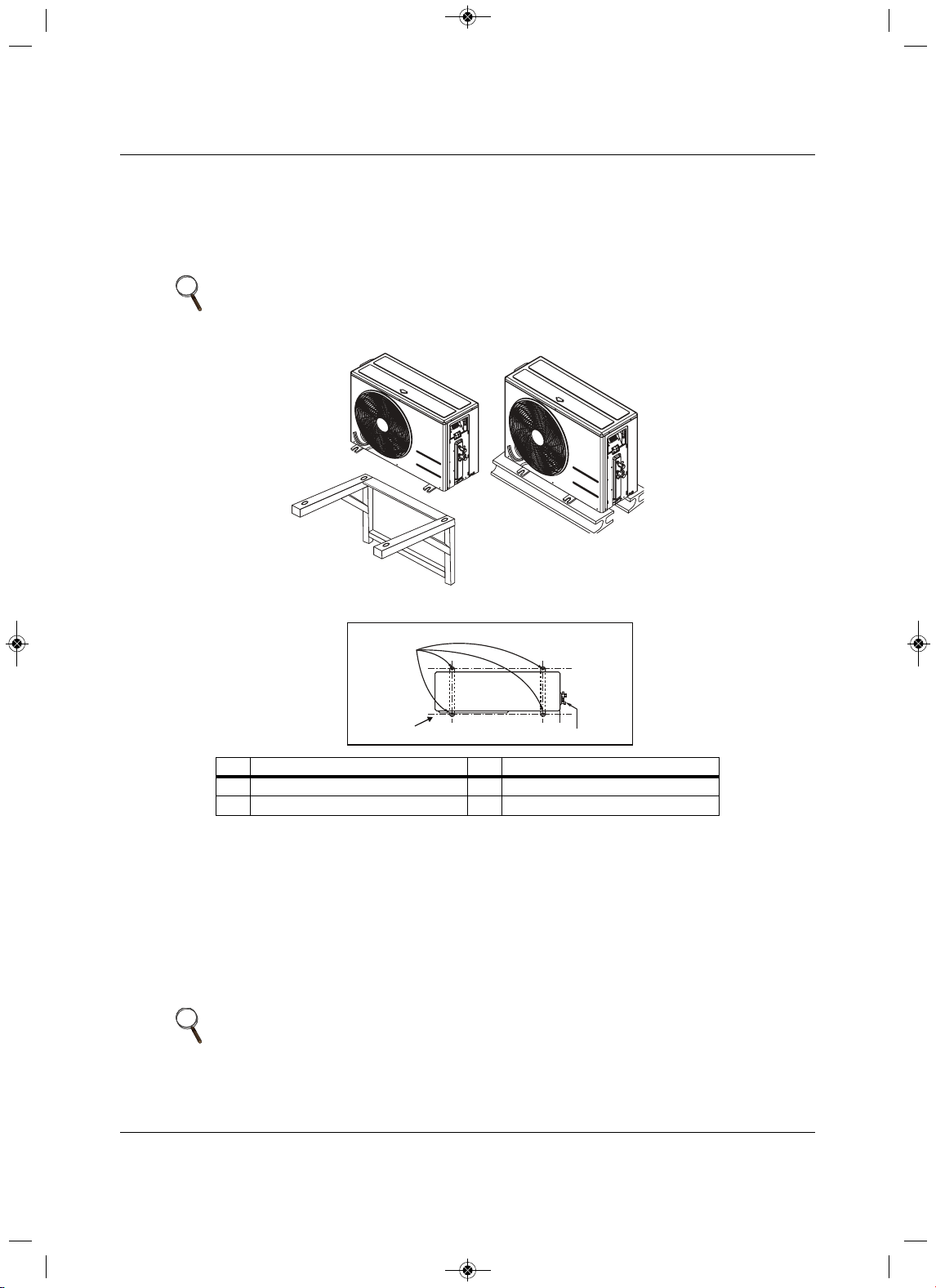
concrete or rigid mount. See Figure 3-3. Follow app
licable local codes for clearance, mounting, anchor
and vibrations attenuation requirements.
Figure 3-3 Outdoor unit mounting methods
3.2.1 Mounting Platform
The underlying structure or foundation must be designed to support the weight of the unit. Avoid placing
the unit in a low-lying area where water may accumulate. When installing the outdoor unit on the wall or
roof top, anchor the mounting base securely to
account for wind, earthquake or vibration.
3.2.2 Tie-downs and Wind Restraints
The strength of the inverter system frame is adequate to be used with field-provided wind restraint tie-
downs. The overall tie-down configuration must be approved by a local, professional engineer.
NOTE
All referenced materials are field-supplied. Images are not to scale.
No.Description No.Description
1Bolt placement and Anti-vibration pad 3Piping connection
2 Foundation
NOTE
Always refer to local code when designing a wind-restraint system.
Top of Unit
1
2
3
MFL67502030 17. 7. 13. 오오 3:05 Page 33
Installation
Liebert
®
SRC
™
User Manual 24
3.2.3 Snow and Ice Conditions
In climates that experience snow build-up, place the unit on a raised platform to ensure condenser air flow.
The raised support platform must be high enough to allow the unit to remain above possible snow drifts.
Mount the unit
on a field-provided snow stand at a minimum height that is equal to the average annual
snowfall plus 20 inches. Design the mount base to prevent snow accumulation on the platform in front or
back of the unit case. If necessar
y, provide a field fabricated hood to keep snow and ice and/or drifting
snow from accumulating on the coil surfaces. Use inlet and discharge duct or hoods to prevent snow or
rain from accumulating on the fan inlet and outlet guards.
Best practice prevents snow from accumulating
on top of the unit. Consider the tie-down requirements in case of high winds or where required by local
codes.
3.3 Clearance requirements
Proper airflow through the outdoor unit coil is critical for correct unit operation. When installing, consider
service, inlet and outlet, and minimum allowable space requirements as illustrated in Figure3-4.
3.3.1 Outdoor Unit Clearance
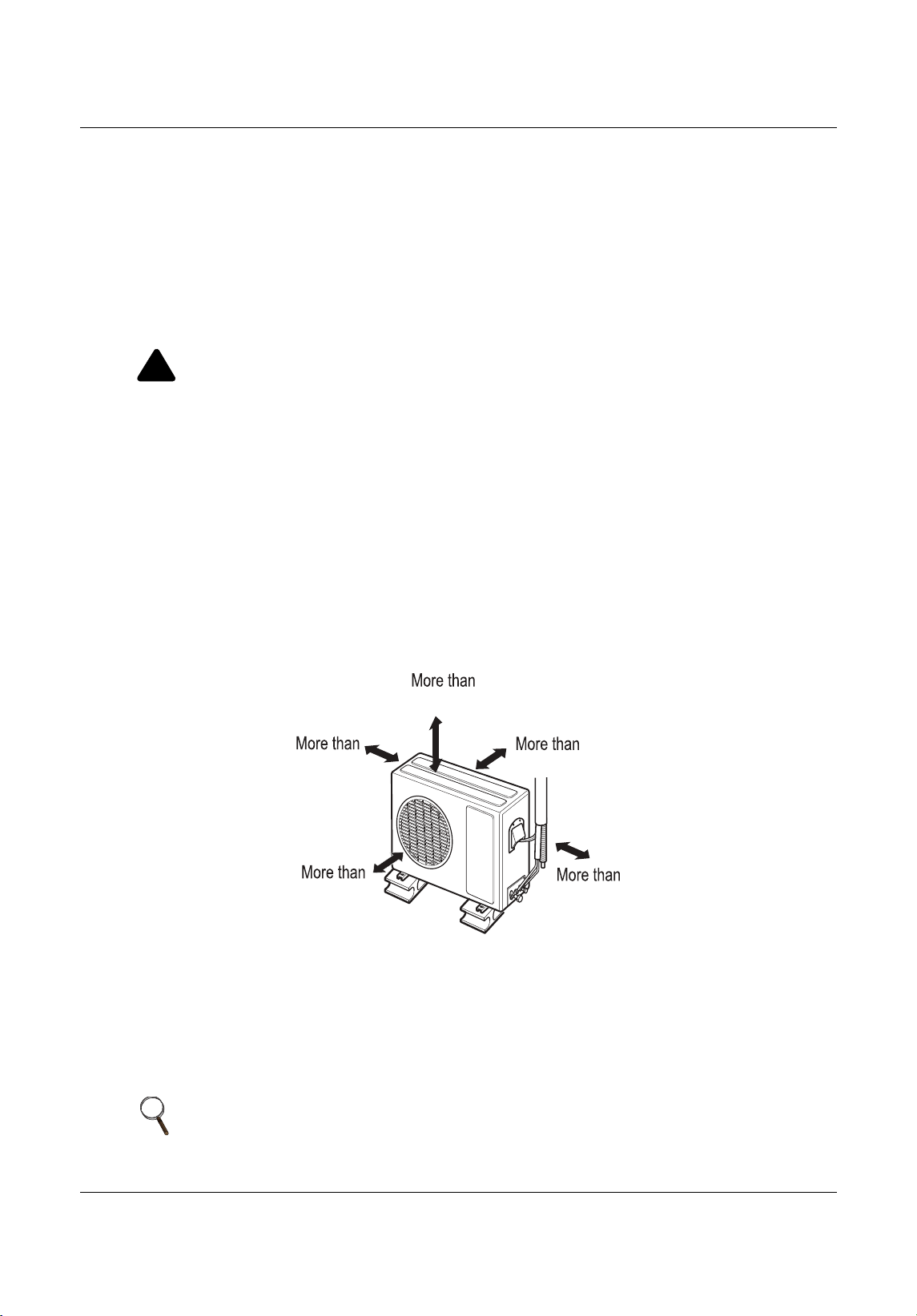
Specific clearance requirements are for the wall-mount systems. Figure3-4 shows the o verall minimum
clearances that must be observed for safe operation and adequate airflow around the outdoor unit.
Figure 3-4 Outdoor-unit clearances
When placing the outdoor
unit under an overhang, awning, sunroof or other “roof-like” structure, observe
the clearance requirements (as shown in Figure3-5) for height in relation to the unit. This clearance
ensures that heat radiation from the condenser is not restricted around the
unit. See Figures 3-6 and 3-7
for recommendations when other obstacles are present.
Adhere to all clearance requirements if installing the unit on a roof. Be sure to level the unit and ensure that
the unit is adequately anchored. Consult l
ocal codes for roof-top mounting requirements.
!
CAUTION
Risk of run-off water freezing on sidewalks and driveways. Can cause falls and injuries. When
selecting the location for the outdoor unit, be sure to choose an area where run-off from defrost will
not accumulate and freeze on sidewa
lks or driveways.
NOTE
Do not place the unit where animals and/or plants will be in the path of the
warm air, or where the warm air and/or noise will disturb neighbors.
12
28
24
12
24
Unit: Inch
MFL67502030 17. 7. 13. 오오 3:05 Page 34
Installation
25 Liebert
®
SRC™ User Manual
Figure 3-5 Outdoor-unit sunroof/awning clearances
Figure 3-6 Clearances when there are obstacles on both air-inlet and air-ou
tlet sides
Figure 3-7 Clear ances when there are obstacles above and on both air-inlet and air-outlet sides
NOTE
In Figures 3-6 and 3-7, the obstacle on the outlet side is lower than the
outdoor unit.
More than
12
More than
12
More than
28
Unit: Inch
More than
24
Minimum
28
Minimum
12
Unit: Inch
M
inimum
12
79
24
Minimum 28
Unit: Inch
MFL67502030 17. 7. 13. 오오 3:05 Page 35
Installation
Liebert
®
SRC
™
User Manual 26
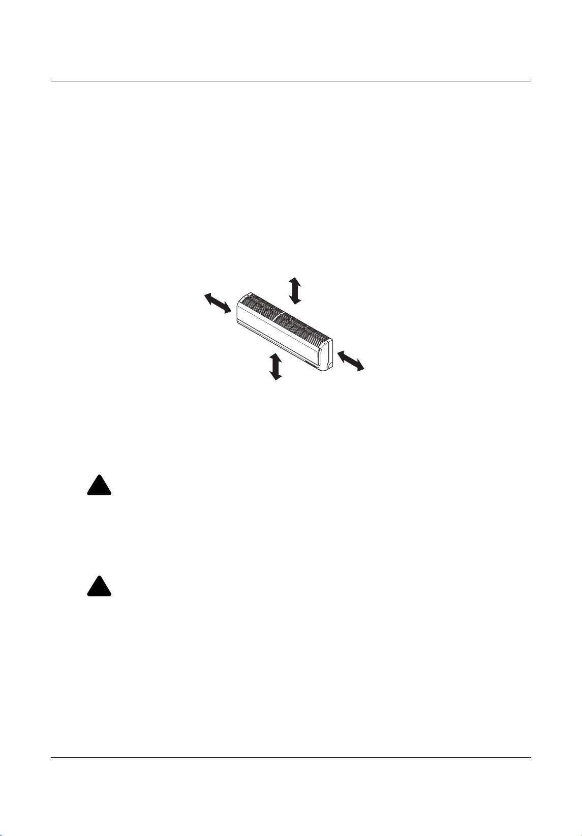
3.3.2 Indoor Unit Clearance
Follow recommended practices when choosing an indoor location for the wall-mounted indoor unit.
•Keep unit away from any indoor steam or excessive heat.
•No obstacles should be placed around the unit.
• Condensation drain (leakage piping) should be routed
away from the unit.
• Do not install near a doorway.
• Clearance gap between any wall or enclosure and the left or right side of the unit must be greater than
4 inches, Figure 3-8.
•From the top of the unit to the ceiling, there must
be greater 8 inches of clearance, see Figure 3-8.
• Unit should be at least 6.5 feet from the floor for adequate clearance.
Figure 3-8 Indoor unit clearance requirements
3.4 Installing the Indoor Unit
3.4.1 Mounting the Installation Plate to the Wall (SRC18)
Follow this procedure and best practices when mounting the indoor unit’s plate to a wall.
!
WARNING
Risk of electrical shock. Can cause injury or death.
• When choosing a location for the wall-mount plate, be sure to take into consideration routing of
wiring for power outlets within the wall. Avoid contact with hazardous voltage wiring.
• Use caution
when drilling holes through the walls for the purposes of piping connections.
Refer to 3.4.3 - Drilling a Piping Hole in the Wall, as you following the plate-installation
procedure.
!
WARNING
Risk of improper mounting.Can cause building and equipment damage, serious injury or death
Select the location carefully. Unit should be anchored to a strong wall to prevent the unit from
falling or unnecessary vibration during operation. Consult a structural engineer
to determine the
suitability of the wall for mounting and the recommended fastening method.
Minimum clearance
from ceiling - 8”
More than 4 inches
More than
4 inches
At least 6.5 feet from the floor
MFL67502030 17. 7. 13. 오오 3:05 Page 36
Installation
27 Liebert
®
SRC™ User Manual
1. Before installation of the plate, confirm the position of the screw types (A or B) between the chassis
and the installation plate, Figure 3-9.
Figure 3-9 Inst allation-plate screws for SR
C18
2. Depending on indoor-unit model refer to Figure 3-10 and mount the plate as follows:
• Use the provided screws and mount the installation plate horizontally by aligning the centerline
using a leveling too l.
• Observe the
left and right rear piping clearance when drilling into the wall.
Figure 3-10 Piping clearance for SRC18 plate
A-Type
B-Type
Unit: Inch
Ø2-19/32
Ø2-19/32
2 -11/16
2-3/16
Right rear
piping
Left rear
piping
Installation Plate
Measuring Tape
Measuring Tape
Hanger
Place a level on raised tab
Unit Outline
8-3/32
4-3/32
18-3/32 22-13/32
MFL67502030 17. 7. 13. 오오 3:05 Page 37
Installation
Liebert
®
SRC
™
User Manual 28
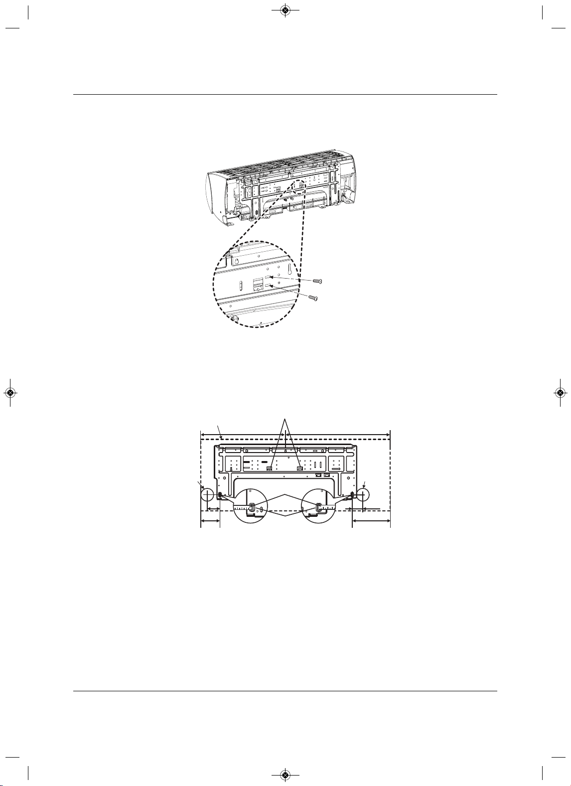
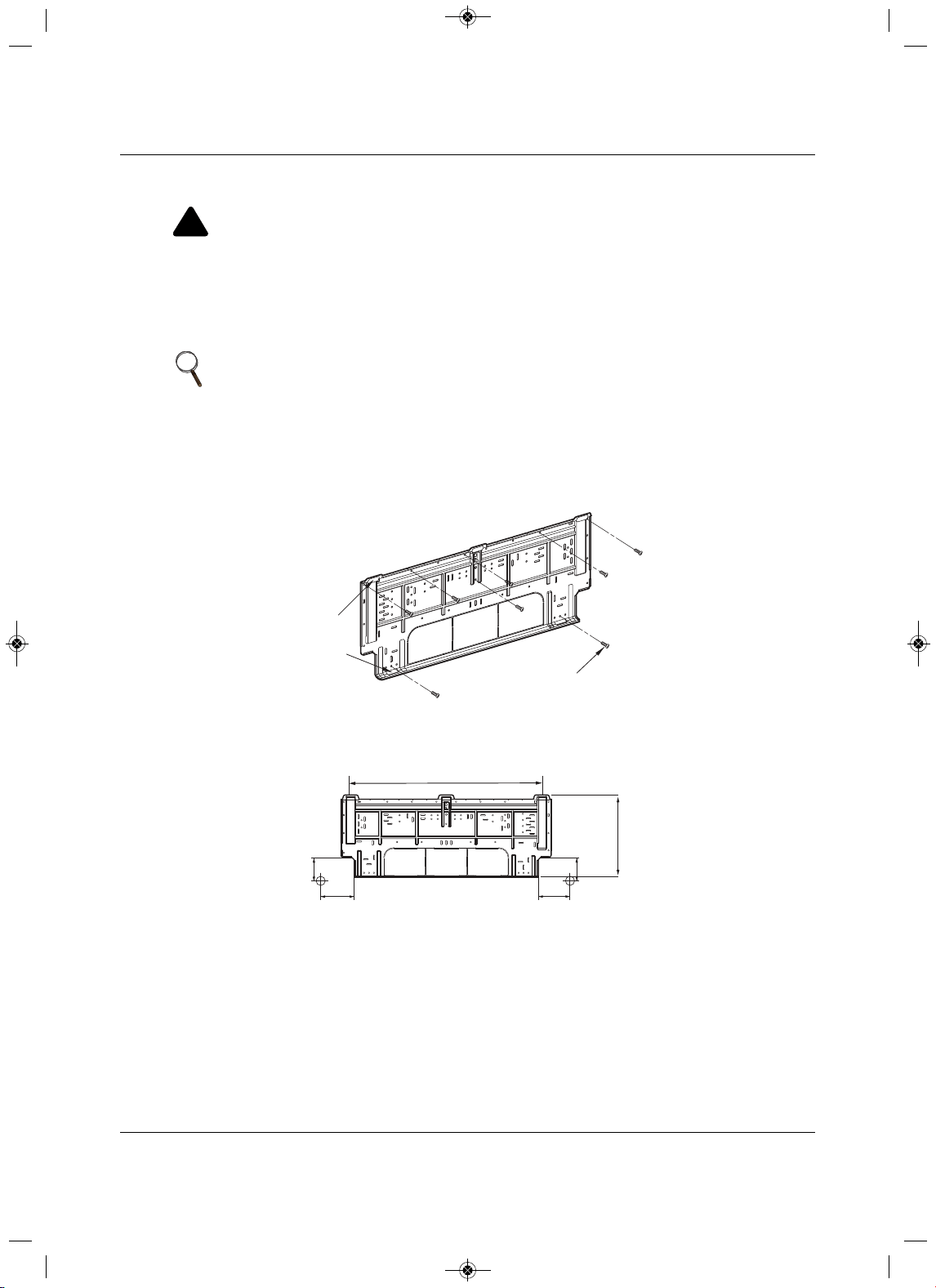
3.4.2 Mounting the Installation Plate to the Wall (SRC24, SRC36)
Follow this procedure and best practices when mounting the indoor unit’s plate to a wall.
1. Use the provided screws, mount the installation plate horizontally by aligning the centerline using a
leveling tool, Figure3-11.
Figure 3-11
Installation-plate screws for SRC24 and SRC36
2. Observe the left and right rear piping clearance when drilling into the wall, Figure3-12.
Figure 3-12 Piping clearance for SRC24 and SRC36 plate
!
WARNING
Risk of electrical shock. Can cause injury or death.
• When choosing a location for the wall-mount plate, be sure to take into consideration routing of
wiring for power outlets within the wall. Avoid contact with hazardous voltage wiring.
• Use caution
when drilling holes through the walls for the purposes of piping connections.
Refer to 3.4.3 - Drilling a Piping Hole in the Wall, as you following the plate-installation
procedure.
NOTE
Select the location carefully. Unit should be anchored to a strong wall to
prevent unnecessary vibration.
Chassis
Hook
Type "A" Screws
Left rear piping Right rear piping
1-11/16
4-11/32
4-11/16
Unit: Inch
1-11/16
30-
11/16
13-
3/16
MFL67502030 17. 7. 13. 오오 3:05 Page 38
Installation
29 Liebert
®
SRC™ User Manual
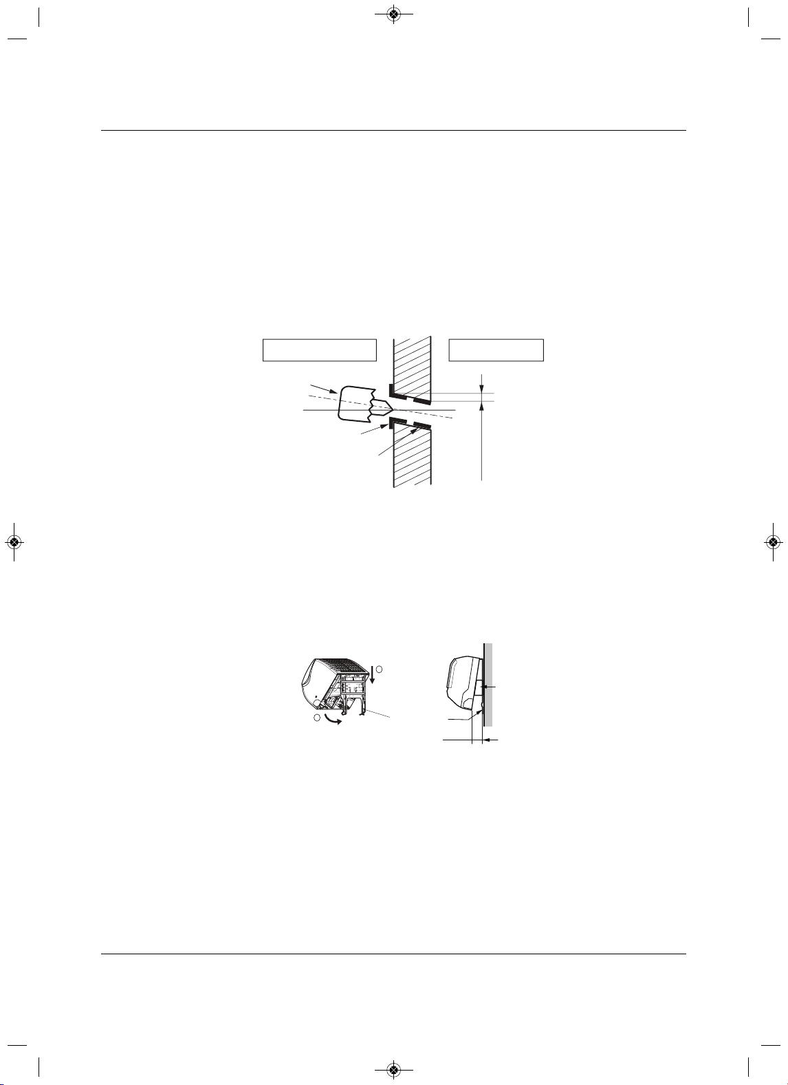
3.4.3 Drilling a Piping Hole in the Wall
Follow the left or right piping-clearance recommendations.
1. Using a 2-5/8 in. (0.65 mm) hole-core drill bits, drill a hole at either the right or left side of the wall
mounting, Figure 3-13.
• The slant of the hol
e should be 3/16 to 5/16 of an inch from level with an upward slant on the
indoor-unit side and downward on the outdoor-unit side.
2.Finish-off the newly-drilled hole as shown in Figure 3-13 with a bushing and
sleeve covering.
• The sleeve and bushing prevents damage to the tubing/bundling of the piping.
Figure 3-13 Drilling a piping hole
3.4.4 Mounting the Indoor Unit to the Plate
1.Hook the indoor unit onto the upper portion of the installation plate, Figure 3-14.
2.Engage the hooks at the top of the indoor unit with the upper edge of the installation plates.
• Make sure that the hooks are properly seated
on the installation plate by moving the unit left and
right.
Figure 3-14 Hook the top of the unit to the plate
(3/16"~5/16")
Indoor
WALL
Outdoor
Bushing
Core Drill
Sleeve
Installation plate
Indoor uni t
3”
Spacer
1
2
MFL67502030 17. 7. 13. 오오 3:05 Page 39
Installation
Liebert
®
SRC
™
User Manual 30
3. Move the bottom of the unit toward the installation plate to anchor to wall, Figure 3-15.
•It helps to press the lower-left and -right sides of the unit against the installation plate until the
hooks engage in their
slots.
•You will hear a clicking sound as the bottom attaches to the installation plate.
Figure 3-15 Move the bo ttom of the unit to the plate and attach to p
late
4. Finish by inserting 2 type “C” screws into the bottom of the installation plate, Figure 3-16.
• As you insert the screws, pay attention to the position of the piping through any wall, as shown in
the figure.
Figure 3
-16 Insert and tighten screws
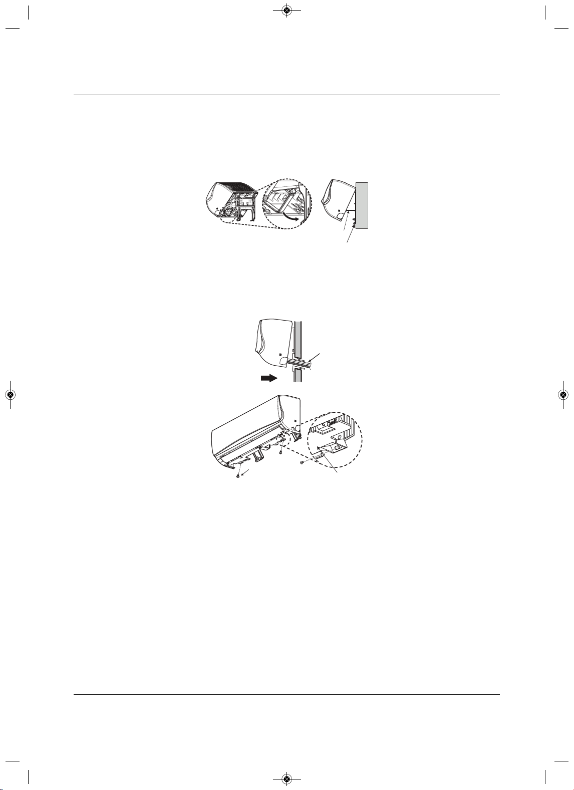
3.4.5 Prepare for Piping/Electrical Connection
1. To prepare the indoor unit for piping, disengage the bottom on the indoor unit from the installation plate
by reversing Step 3 of 3.4.4 - Mounting the Indoor Unit to the Plate.
• This separates the bottom of
the indoor unit from the wall mount so you can route the drain hose
correctly. Figure 3-17 shows the rear view of the indoor unit.
2. Swing the drain-hose holder (L-bracket) out and anchor as show in Figure 3-15.
Installation Plate
Drain Hose
Holder
L-bracket
Type 'C' Screws
Bo om of
Indoor Unit
Indoor Unit
Piping
Thr ough
Wall
MFL67502030 17. 7. 13. 오오 3:05 Page 40
Installation
31 Liebert
®
SRC™ User Manual
3. Refer to 5.0- Piping, to continue with the piping connections to the indoor unit.
– or –
Refer to 6.0- Electrical Connections, to continue with the conduit/electrical wiring to the indoor unit.
Figure 3-17 Rear
view of indoor unit
3.5Pump Down Procedure
This procedure is performed when a unit must be relocated or the refrigerant circuit is serviced. “Pumping
down” is a term that means collecting all refrigerant into the outdoor unit without the loss of any refrigerant.
Use the following procedure to safely collect refrigerant back
into the outdoor unit. Always adhere to and
be familiar with local codes regarding the handling of refrigerant.
The system must be placed in Cooling mode to proceed with the pump-down procedure. Refer to 8.3 -
Enabling Coo
ling-only Mode, for the steps.
1. Connect a low-pressure gauge with manifold hose to the charge port on the gas-line service valve.
2. Open the gas-line service valve half-way.
!
CAUTION
Risk of inhalation of refrigerant gas. Can cause illness and injury.
Never air purge with refrigerant as it can cause refrigerant leakage.
NOTE
Use a vacuum pump that can evacuate down to 500 microns.
1. If moisture remains in the piping after the system is evacuated for
2 hours, break the vacuum (down to 7.5 psi with nitrogen gas).
2. Evacuate the system again with the vacuum pump for at least 1 hour to
500 microns.
3. If the system does not reach 500 microns within 2 hours, repeat the
vacuum break and evacuation procedure until the gauge does not rise.
!
CAUTION
Risk of exposure or contact with refrigerant. Can cause injury and illness.
Refrigerant is toxic and too cold for safe human contact. Do not inhale or handle refrigerant
directly.
NOTE
Perform pump-down procedure only in cooling mode.
Installaon Plat e
Drain Hose
Drain Hose Holder
MFL67502030 17. 7. 13. 오오 3:05 Page 41

Installation
Liebert
®
SRC
™
User Manual 32
3. Purge the air in the manifold hose using the refrigerant.
4. Close the liquid line service valve completely.
5. Turn on the cooling-unit’s power switch and start cooling-mode operation, 8.3 - Enabling Cooli
ng-
only Mode.
6. Observe the pressure gauge reading.
• When the gauge reads 1 to 0.5 kg/cm
2
(14.2 to 7.1 psig), fully-close the gas-line valve and
immediately turn of the cooling unit.
Pump-down is complete, and all refrigerant should be collected into the outdoor unit.
MFL67502030 17. 7. 13. 오오 3:05 Page 42
Installation Checklist
33 Liebert
®
SRC™ User Manual
4.0 Installation Checklist
Major Component Rough-in
___ 1. Unit was connected properly per local code and the product installation procedures.
___ 2. All literature and bagged accessories have been removed from the fan discharge.
___ 3.Indoor unit was installed, properly supported, and located indoors in a non-corrosive environment.
___ 4. Unit’s gravity condensate drain line
was connected and routed where it properly drains away or, if
installed in a mechanical room, was connected and properly routed to a drain terminal.
Piping and Insulation
___ 1. Copper
___ 2. Over 5/8 inches—Rigid ACR only
___ 3. 5/8 inches and under—can use soft ACR.
___ 4. 15% silver brazing material only.
___ 5. All refrigerant pipes and valves were insulated separately. Insulation butts up against the walls of
the indoor units. No gaps
or cracks. Insulation was not compressed at clamps and hangers.
Brazing Practices
___ 1. Medical grade (there are 4 available) dry nitrogen for purging during brazing was used (constant
3psi while brazing).
Installation
Refer to the details in the Installation section for more information on any procedure.
Refrigerant Piping
___ 1. All pipe materials were properly stored, capped, and clean. All burrs were removed after cutting
and pipe ends were reamed before brazing.
___ 2. During refrigerant pipe installation, for each segment of pipe, a record was made of the pipe length
(including expansion loops, offsets, doub
le-back sections), and sizes, as well as the quantity and
type of elbows used.
___ 3. All long runs of straight pipe were provided with expansion loops.
___ 4. A torque wrench and backup wrench were used to tighten all flare connections.
___ 5. The back side of
all flares were lubricated with a small drop of PVE refrigeration oil before
tightening flare fittings.
___ 6.Ensure all field-made flares are 45°. Used factory-suppled flare nuts only.
___ 7. Pipe segments were properly supported and all wall penetrations were sleeved.
___ 8. Pipe insulation was not compressed at any point.
___ 9.No oil traps, solenoid valves, sight glasses, filter driers, or any other unauthorized refrigerant
specialties were present.
___ 10. Best practice including a minimum of 20-inch straight pipe was installed between
each elbow .
MFL67502030 17. 7. 13. 오오 3:05 Page 43

Installation Checklist
Liebert
®
SRC
™
User Manual 34
Power Wire and Communication Cables
___ 1. Power wiring was connected to a single-phase 208 – 230-V source.
___ 2.Ground wire was installed and properly terminated at the unit.
___ 3. The power supplied was clean with voltage fluctuations with specifications. (±10% of nameplate).
___ 4. Power wiring
to the outdoor unit was installed per all local electrical code requirements.
___ 5. Power wiring to the indoor unit was installed per all local electrical code requirements.
___ 6.Factory-supplied cable was used between the indoor unit and the thermostat. No cables
were
spliced and no wire caps are present.
___ 7. Communication type RS-485-BUS type.
___ 8. All communication cables were a minimum of 18-AWG, 4 conductor, shielded, and stranded, with
insulation material per local code. Cable segment shield were tied together
.
___ 9. Used appropriate crimping tool to attach ring or spade terminals at all power wiring and control
cable terminations.
___ 10. All power and control wires were properly separated using the recommended distance provided in
the installation manual.
MFL67502030 17. 7. 13. 오오 3:05 Page 44
Piping
35 Liebert
®
SRC™ User Manual
5.0Piping
5.1Piping Preparation
5.1.1 Creating a Flare Fitting
!
WARNING
• Do not allow the refrigerant to leak during brazing. If the refrigerant combusted, it generates a
toxic gas that can cause physical injury or death.
• Do not braze in an enclosed location, and always test for gas leaks before/after brazing. Gas
leaks
can cause physical injury or death.
• After brazing, check for refrigerant gas leaks. Refrigerant gas leaks can cause physical injury or
death.
NOTE
1. Do not use kinked pipe cause by excessive bending in one specific area
on its length.
2. Braze the pips to the service-valve pipe stem of the outdoor unit.
!
WARNING
Risk of refrigerant leaks. Can cause equipment malfunction, injury, sickness and death from
suffocation due to oxygen depletion in closed, non-ventilated areas.
When selecting flare fittings, always use a 45° fitting rated for use with high-pressure refrigerant
R410A. Verify that all fittings comply with local, state, or federal standards.
NOTE
One of the main causes of refrigerant leaks is defective flared connections.
Create flared connections using the procedure shown in Figure 5-1 and steps
that follow.
MFL67502030 17. 7. 13. 오오 3:05 Page 45
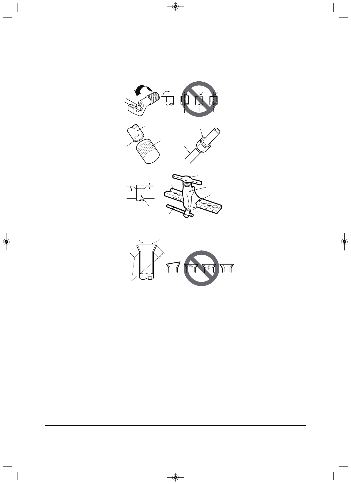
Piping
Liebert
®
SRC
™
User Manual 36
Figure 5-1 Creating a fla red fitting
1. Cut the pipe to length.
• Measure the distance between the indoor unit and the outdoor unit.
• Cut the pipes a littler longer than the measured distance.
• Cut the cable 4.9ft longer
than the pipe length.
2. A. Remove the burrs.
• Completely remove all burrs from pipe ends.
• When removing burrs, point the end of the copper pipe down to avoid introducing foreign materials
into the pipe.
B. Slide the flare nut onto the copper tube.
3.Fl
aring the pipe end.
• Use the proper size flaring tool to finish flared connections as shown in Figure 5 -1.
• Always create a 45° flare when working with R410A. Refer to the Warning preceding this
procedure.
Figure 19: Creating a Flare Fitting
Copper
tube
90°
Slanted Uneven Rough
Pipe
Reamer
Point
down
Flare nut
Copper
tube
Bar
Copper pipe
Clamp handle
Red arrow
Cone
Yoke
Handle
Bar
"A"
Slanted
Inside is shiny with no scratches
Smooth
Even length
Damaged
surface
Cracked Uneven
thickness
Incorrect Flares
1.
2A. 2B.
3.
4.
MFL67502030 17. 7. 13. 오오 3:05 Page 46
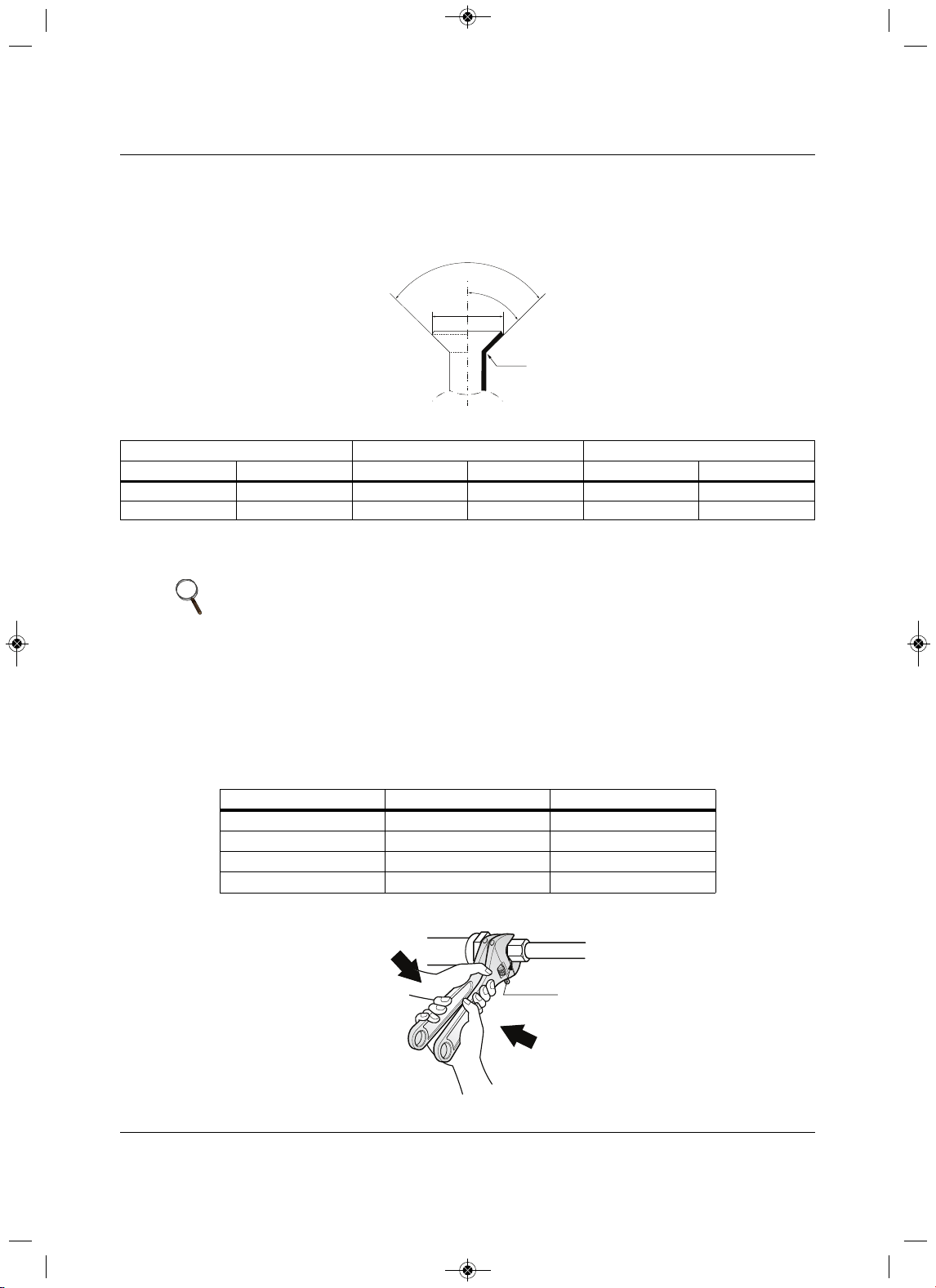
Piping
37 Liebert
®
SRC™ User Manual
4. Carefully inspect the flared pipe end.
• Compare the geometry with Figure 5-1 and the dimensions detailed in Figure 5-2 and Table 5-1.
Figure 5-2 Flared-connection dimensions
5.1.2 Tightening Flare Nuts
1. When connecting the flare nuts, coat the flare (inside and outside) with polyvinyl ether (PVE)
refrigeration oil only.
2.Initially, hand tighten the flare nuts using 3 or 4 turns.
3.Finishing tightening the flare nuts using both a torque wrench and a bac
kup wrench as shown in
Figure 5-3.
Figure 5-3 Tightening the flare nuts
Table 5-1 Flared-connection dimensions
Pipe “A”Thickness
Vapor (in. O.D.) Liquid (in. O.D.) Vapor (i n.) Liquid (in.) Vapor (in.) Liqui d (in.)
1/2 1/4 1/8 1/16 1/8 1/8
5/8 3/8 1/8 1/16 1/16 1
/8
NOTE
Do not use polyolyester (POE) or any other type of mineral oil as a thread
lubricant. These lubricants are not compatible with PVE oil used in this system
and create oil sludge leading to equipment damage and system malfunction.
Table 5-2 Tightening torque for flare nuts
Pipe size (in. O.D.) Tightening torque (ft-lbs)Width o f flare (A [in.])
1/4
∅
13.9 – 18 1/8
3/8
∅
24.5 – 30.31/8
1/2
∅
39.7 – 47.7 1/8
5/8
∅
45.5 – 59.2 1/16
90°
2
45°
2
A
R=0.4~0.8
Union
MFL67502030 17. 7. 13. 오오 3:05 Page 47
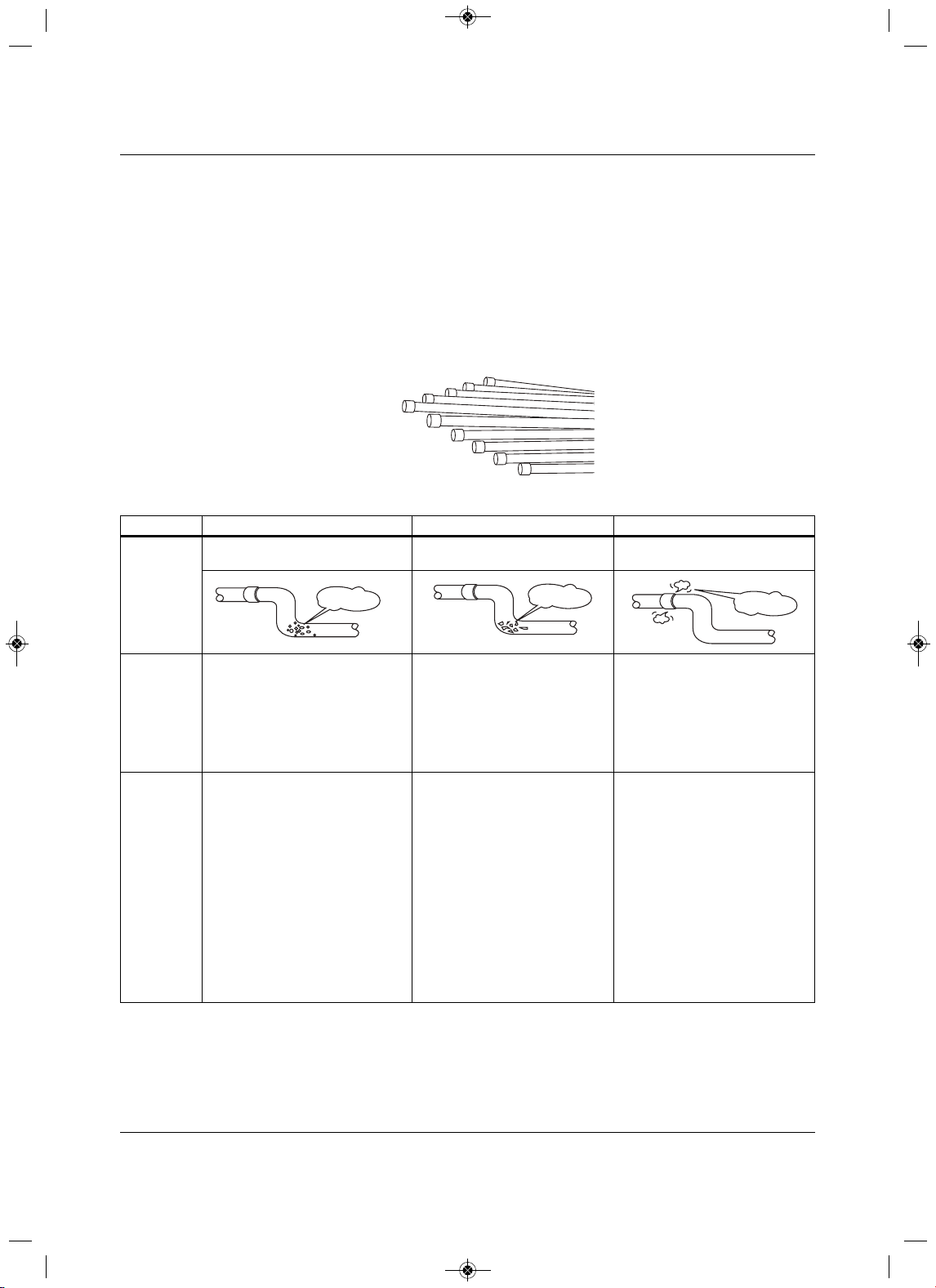
Piping
Liebert
®
SRC
™
User Manual 38
5.1.3 Loosening Flare Nuts
Always use 2 wrenches to loosen the flare nuts.
5.2 Piping Materials and Handling
Pipes used for the refrigerant piping system must include the specified thickness, and the interior must be
clean.
While handling and storing, do not bend or damage the pipes, and take care not to contaminate the interior
with dust, moisture, etc. See Table 5
-3 for care of piping.
Figure 5-4 Keep piping capped while storing
Table 5-3Three principles of refrigerant piping
DryClean Airtight
Principles No moisture should be inside the
piping.
No dust should be inside the
piping.
No leaks should occur.
Problems
Caused
• Significant hydrolysis of refrigerant
oil.
• Refrigerant oil degradation.
• Poor insulation of the
compressor.
•System does not operate properly.
•EEVs, capillary tubes are clogged.
• Refrigerant oil degradation.
•Poor insulation of the
compressor.
•System does not operate
properly.
•EEVs and capillary tubes
become clogged.
• Refrigerant gas leaks/shortages.
• Refrigerant oil degradation.
•Poor
insulation of the
compressor.
•System does not operate
properly.
Solutions • Remove moisture from the piping.
• Piping ends should remain capped
until connections are complete.
• Do not install piping on a rainy day.
• Connect piping properly at the
unit’s side.
• Remove
caps only after the piping
is cut, the burrs are removed, and
after passing the piping through
the walls.
•Evacuate system to a minimum of
500 microns and ensure the
vacuum holds at that level for 24
hours.
• Remove dust from the piping
.
•Piping ends should remain
capped until connections are
complete.
• Connect piping properly at the
side of the unit.
• Remove caps only after the
piping is cut and burrs are
removed.
• Retain the cap on the piping
when passing it through walls,
etc.
• Test system for air-tightness.
• Perform brazing proc3edures
that comply with all applicable
standards.
• Perform flaring procedures that
comply with all applicable
standards.
• Perform flanging procedures that
comply with all applicable
standards.
•Ensure that refrigerant lines are
pressure-test to
550 psig.
-
Moisture
Dust
Leaks
MFL67502030 17. 7. 13. 오오 3:05 Page 48
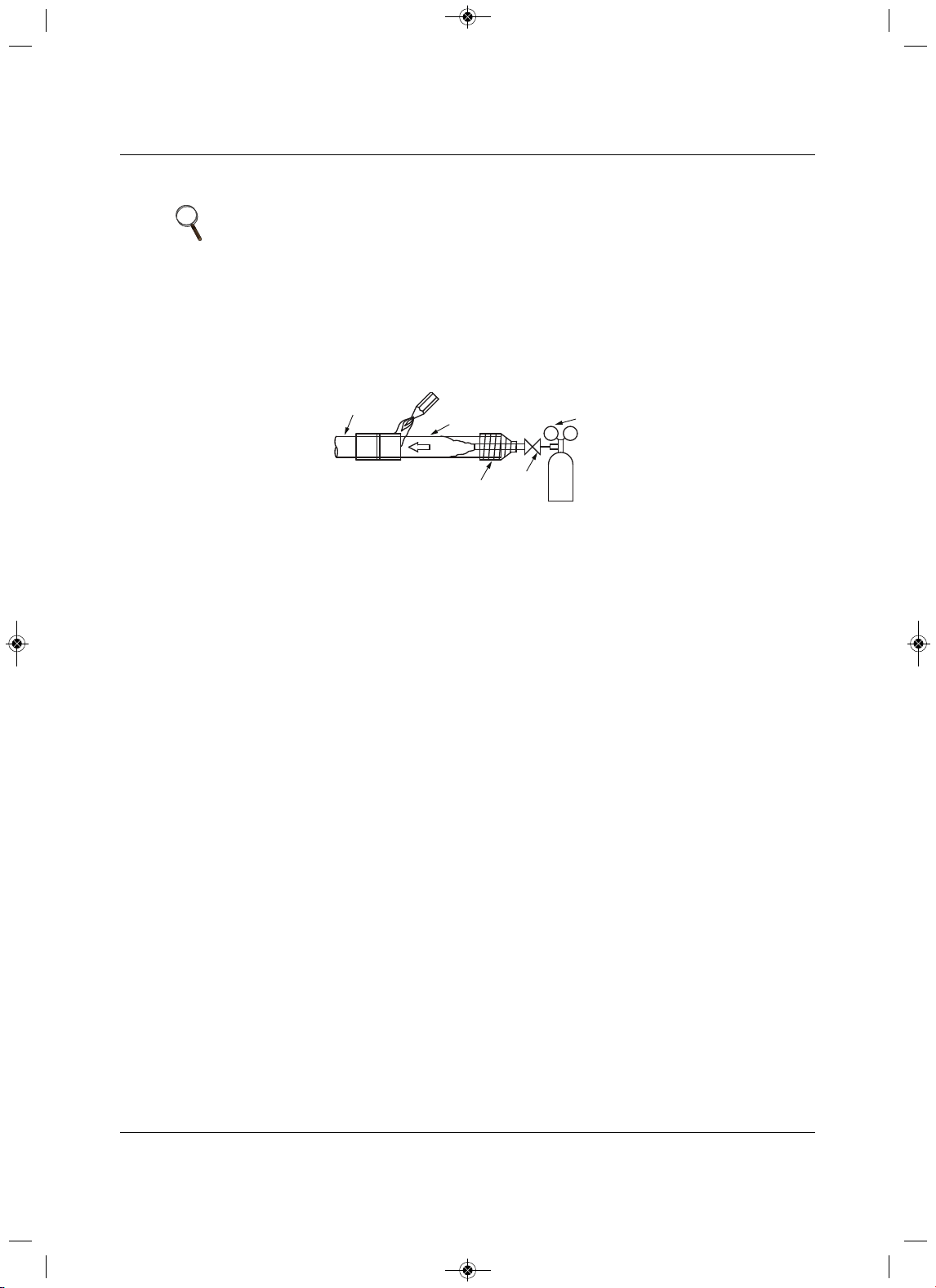
Piping
39 Liebert
®
SRC™ User Manual
5.2.1 Brazing Practices
All joints are brazed in the field. Refrigeration-system components contain very small capillary tubes, small
orifices, electronic expansion valves, oil separators, and heat exchangers that can easily become blocked.
Proper system operation depends on the installer using best practices and utmost
care while assembling
the piping system.
Figure 5-5 Refrigerant-pipe brazing
• While brazing, use a dry-nitrogen purge operating at a minimum pressure of 3psig and maintain a
steady flow.
• Before assembly, use dry nitrogen to blow cl
ean all pipe sections.
• Use a tubing cutter, do not use a saw to cut pipe. De-burr and clean all cuts before assembly.
• Store pipe stock in a dry place. Keep pipe capped and clean.
• Use adapters to assemble different sizes of pipe.
• Do
not use flux, soft solder, or anti -oxidant agents.
• Use a 15% silver phosphorous copper-brazing alloy to avoid overheating and produce good flow.
• Protect isolation valves, electronic expansion valves, and other heat-sensitive control components
from excessive heat with
a wet rag or a heat-barrier spray product.
NOTE
It is imperative to keep the piping system free of contaminants and debris
such as copper burrs, slag, or carbon dust during installation. Contaminants
can result in mechanical failure of the system.
Pressure-reducing
Valve
Valve
Taping
Nitrogen
Pipe to
be brazed
Refrigerant
Piping
MFL67502030 17. 7. 13. 오오 3:05 Page 49
Piping
Liebert
®
SRC
™
User Manual 40
5.2.2 Refrigerant-piping System Insulation
For specific insulation procedures, see 5.4 - Piping Insulation.
5.2.3 Selecting Field-supplied Copper Tubing
Copper is the only approved refriger ant-pipe material for use with the Liebert SRC, and Emerson
recommends seamless phosphorous deoxidized ACR type copper pipe, hard-drawn rigid type “K” or “L,” or
annealed-tempered, copper pipe.
• Drawn temper (rigid) ACR copper tubing is availabl
e in sizes 3/8 through 2-1/8 inches (ASTM B 280,
clean, dry, and capped).
• Annealed temper (soft) ACR copper tubing is available in sizes 1/4 through 2-1/8 inches (ASTM B 280,
clean, dry, and capped).
NOTE
All refrigerant piping, field-provided isolation ball valves, service valves, and elbows shall be
completely insulated using closed-cell pipe insulation. The liquid and vapor lines must be insulated
separately.
To prevent heat loss/heat gain through the refrigerant5 piping, all refrigerant piping, including liquid
lines and vapor lines shall be insulated separately. Insulation shall be a minimum 1/2-in. thick, and
thickness may need to be increased based-on ambient conditions and local codes.
All insulation joints shall be glued with no air gaps. Insulation material shall fit snugly against the
refrigeration pip3e with no air space between it and the pipe. Insulation passing through pipe
hangers, inside conduit, and/or sleeves must not be compressed. Protects insulation inside
handers and supports with a second layer. All pipe insulation exposed to the sun and outdoor
elements shall be properly protected with PVC, aluminum vapor barrier, or alternatively placed in a
weather-resistant enclosure such as a pipe rack with a top cover and meet local codes.
The design engineer should perform calculations to determine if the factory-supplied insulation
jackets are sufficient to meet local codes and avoid sweating. Add additional insulation if
necessary. Mark all pipes at the pint where the insulation jacket ends. Remove the jacket. Install
field-provided insulation on the run-out and main-trunk pipes first. Peel the adhesive glue protector
slip from the insulation jacket and install the clam-shell jacket over the fitting.
NOTE
Tube wall thickness should meet local code requirements and be approved for
an operating pressure of 551 psi. If local code does not specify wall thickness,
Emerson suggests using tube thickness per Table 5-4. When bending tubing,
try to keep the number of bends to a minimum, and use the largest radii
possible to reduce the equivalent length of installed pipe. Also, bending radii
greater than 10 pipe diameters can minimize pressure drop. Be sure that no
traps or sags are present when rolling-out soft copper-tubing coils.
Table 5-4 ACR copper-tubing material
Type Seamless phosphorous deoxidized
Class UNS C12200 DHP
Straight Lengths H58 temper
Coils O60 temper
MFL67502030 17. 7. 13. 오오 3:05 Page 50
Piping
41 Liebert
®
SRC™ User Manual
5.2.4 No Pipe Size Substitutions
Use only the pipe size recommended by this manual. Using a different size is prohibited and may result in
a system malfunction or failure to work at all.
Table 5-5 Piping-tube thickness
OD (in.) 1/4 3/81/25/83/4 7/81-1/81-3/81-5/8
Material Rigid type “K” or “L” and a soft ACR acceptable Rigid type “K” or “L” only
Min. Bend
Radius (in.)
.563 .9375 1.52.25 3.03.03.5 4.0
4.5
Min. Wall
Thickness
(in.)
.03 .03 .035 .040 .042 .045 .050 .050 .050
Table 5-6 ACR copper-tubing dimensions and physical characteristics
1-4
Nominal
Pipe Outside
Diameter
(in.)
Actual
Outside
Diameter
(in.)
Drawn Temper Annealed Temper
Nominal
Wall
Thickness
(in.) Weight (lb/ft)
Cubic ft per
Linear ft
Nominal
Wall
Thickness
(in.) Weight (lb/ft)
Cubic
ft per
Linear ft
1/4 0.250 ———0.030 0.081 .00020
3/80.375 0.030 0.126 .00054 0.032 0.134.00053
1/20.500 0.035 0.198 .00101 0.032 0.182 .00103
5/80.625 0.0400.285 .00162 0.035 0.251 .00168
3/4 0.750 0.0420.362 .002420.0420.362 .
00242
7/80.875 0.0450.455 .00336 0.0450.455 .00336
1-1/81.125 0.050 0.655 .00573 0.050 0.655 .00573
1. All dimensions provided are in accordance with ASTM B280 – Standard.
2. Design pressure = 551 psig.
3. ACR tubing is available as hard-drawn or annealed (soft) and are suitable for use with R410A refrigerant.
4. The Copper Tube Handbook, 2010, Copper Deve
lopment Association Inc., 260 Madison Avenue, New York, NY 10016.
NOTE
• Commercially-available piping often contains dust and other materials.
Always blow it clean with a dry, inert gas.
• Prevent dust, water or other contaminants from entering the piping during
installation. Contaminants can cause mechanical failure.
MFL67502030 17. 7. 13. 오오 3:05 Page 51
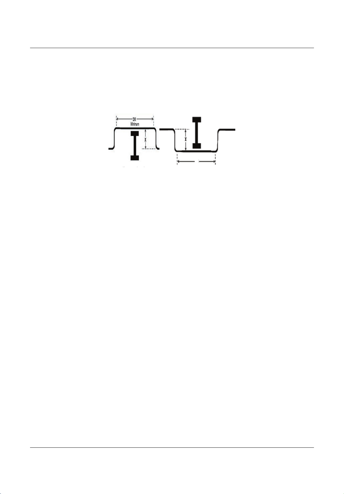
Piping
Liebert
®
SRC
™
User Manual 42
5.2.5 Obstacles
When an obstacle, such as an I-beam or concrete T, is in the path of the planned refrigerant-pipe run, it is
best practice to route the pipe over the obstacle. If adequate space is not available to route the insulated
pipe
over the obstacle, then route the pipe under the obstacle. In either case, it is imperative that the length
of the horizontal section of pipe above or below the obstacle be a minimum of 3-times the longest vertical
rise (or
fall) at either end of the segment, Figure5-6.
Figure 5-6 Installing p iping above and below an obstacle
5.2.6 Copper Expansion and Contraction
Under normal operating conditions, the vapor pipe temperature of a Liebert SRC can vary as much as
280°F. With this large variance in pipe temperature, the designer must consider pipe expansion and
contraction to avoid pipe and fitting fatigue failures.
Refrigerant pipe along with
the insulation jacket form a cohesive unit that expands and contracts together.
During system operation, thermal heat transfer occurs between the pipe and the surrounding insulation.
If the pipe is mounted in free-air space, no natural restriction to movement is present,
if the mounting clips
are properly spaced and installed. When the refrigerant pipe is mounted underground in a utility duct,
stacked among other pipes, natural restriction to linear movement is present. In extreme cased, the
restrictive force of surface friction between insulation
jackets could become so great that natural expansion
ceases and the pipe is “fixed” in place. In this situation, opposing force caused by change in refrigerant
fluid/vapor temperature can lead to stress failure of pipes/fittings.
The refrigerant-pipe support system must be
engineered to allow free expansion to occur. When a
segment of pipe is mounted between two fixed points, provisions must be provided to allow pipe expansion
to naturally occur. The most common method is the inclusion of expansion loops or U-bends. Each
segment of
pipe has a natural fixed point where no movement occurs. This fixed point is located at the
center point of the segment assuming that the entire pipe is insulated in a similar fashion. The natural fixed
point of the pipe segment is typically where the
expansion loop or U-bend should be.
Linear pipe expansion can be calculated using the following formula:
LE = C x L x (T
r
– T
a
) x 12
LE = Anticipated linear tubing expansion (in.)
C = Constant (for copper = 9.2 x 10
-6
in./in.°F)
L = Length of pipe (ft)
T
r
= Refrigerant-pipe temperature (°F)
T
a
= Ambient air temperature (°F)
12 = Inches-to-feet conversion (12 in./ft)
1.From Table 5-7, find the row corresponding with the actual length of the straight pipe segment.
2.Estimate the minimum and maximum temperature of the pipe.
In the column showing the minimum pipe temperature, look up
the anticipated expansion distance. Do
the same for the maximum pipe temperature.
Ab b l
3X
Above an obstacle.
Below an obstacle.
MFL67502030 17. 7. 13. 오오 3:05 Page 52
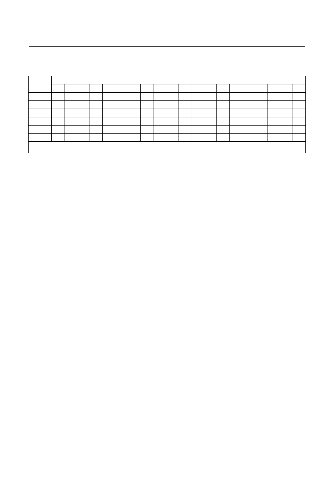
Piping
43 Liebert
®
SRC™ User Manual
3. Calculate the difference in the two expansion distance values.
The result is the anticipated change in pipe length.
Example:
A system is installed and the design shows that there is a 100-foot straight segment of tubing between an
indoor unit and the outdoor unit. When heating, this pipe transports hot gas vapor to the indoor units at
120°F. When cooling, the same tube is a suction
line that returns refrigerant vapor to the outdoor unit at
40°F. Look-up the copper-tubing expansion at each temperature and calculate the difference.
Vapor L ine
Transporting hot vapor: 100-ft pipe at 120°F = 1.40in.
Transporting suction vapor: 100-ft pipe at 40°F = 0.40in
.
Anticipated change in length: 1.40in. – 0.40in. = 1.00 in.
Liquid Line
The liquid temperature remains relatively the same temperature, only direction of flow reverses. Therefore,
no significant change in length of the liquid line is anticipated.
When creating an expansion joint, the joint height shoul
d be a minimum of two times the joint width.
Although different types of expansion arrangements are available, the data for correctly sizing an
expansion loop is provided in Table5-8. Use soft copper with long-radius bends on longer runs or long-
radius elbows
for shorter pipe segments. Using the anticipated linear expansion (LE) distance calculated,
look-up the expansion loop or U-bend minimum design dimensions. If you choose to use other types of
expansion joints, design per ASTM B-88 Standards.
Table 5-7 Linear therma
l expansion of copper tubing, in inches
Pipe
Length
1
Fluid Temperature, °F
35° 40° 45° 50° 55° 60° 65° 70° 75° 80° 85° 90° 95°100°105°110°115°120°125°130°
10
0.04 0.04 0.05 0.06 0.06 0.07 0.08 0.08 0.09 0.09 0.10 0.10 0.11 0.11 0.11 0
.12 0.13 0.14 0.15 0.15
20
0.08 0.08 0.10 0.12 0.13 0.14 0.15 0.16 0.17 0.18 0.19 0.20 0.21 0.22 0.22 0.23 0.26 0.28 0.29 0.30
30
0.12 0.12 0.15 0.18 0.20 0.21 0.23 0.24 0.26 0.27 0.29 0.30 0.32 0.33 0.32 0.35 0.39 0.4
20.44 0.45
40
0.16 0.16 0.20 0.24 0.26 0.28 0.30 0.32 0.34 0.36 0.38 0.400.420.44 0.430.46 0.52 0.56 0.58 0.60
50
0.20 0.20 0.25 0.30 0.33 0.35 0.38 0.400.430.450.480.50 0.53 0.55 0.54 0.58 0.
650.70 0.73 0.75
60
0.24 0.24 0.30 0.36 0.39 0.420.450.480.51 0.54 0.57 0.600.630.66 0.650.690.78 0.84 0.87 0.90
1. Pipe length baseline temperature = 0°F. “Expansion of Carbon, Copper and Stainless Steel Pipe,” The Engineer’s Toolbox,
www.engineeringtoolbox.com.
MFL67502030 17. 7. 13. 오오 3:05 Page 53
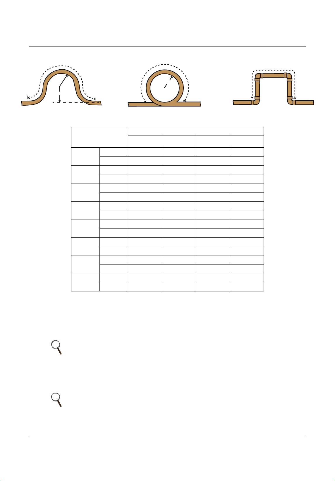
Piping
Liebert
®
SRC
™
User Manual 44
Figure 5-7 Coiled expansion loops and offsets
5.2.7 Pipe Bends
When bending soft copper, use long-radius bends. Refer to Table 5-8 for minimum radius specifications.
5.2.8 In-line Refrigeration Components
Liebert SRC systems are provided with redundant systems that assure oil is properly returned to the
compressor. Sight glasses and solenoid valves may cause vapor to form in the liquid stream.
Table 5-8 Radii of coiled expansion loops and
developed lengths of expansion offsets
Anticipated Linear
Expansion (LE)
(in.)
Nominal Tube Size (OD) in.
1/4 3/8 1/2 3/4
1/2
R
1
6 7 8 9
L
2
38 44 50 59
1
R
1
9 10 11 13
L
2
54 63 7083
1-1/2
R
1
11 12 14 16
L
2
66 77 86 101
2
R
1
12 14 16 19
L
2
77 8999117
2-1/2
R
1
14 16 18 21
L
2
86 99 111 131
3
R
1
15 17 19 23
L
2
94 109 122 143
3-1/2
R
1
16 19 21 25
L
2
102 117 131 155
4
R
1
17 20 22 26
L
2
109 126 140 166
NOTE
Components such as oil traps, solenoid valves, filter-dryers, sight glasses, tee
fittings, and other after-market accessories are not permitted on the
refrigerant-piping system between the outdoor unit and the indoor unit.
NOTE
Over time, dryers may deteriorate and introduce debris into the system. The
designer and installer should verify that the refrigerant-piping system is free of
traps, sagging pipes, sight glasses, filter dryers, etc.
Large Tubing U-bend (>3/4 in.) Loop Small Tubing U-bend (<3/4 in.)
R
L
R
L
L
MFL67502030 17. 7. 13. 오오 3:05 Page 54

Piping
45 Liebert
®
SRC™ User Manual
5.2.9 Field-provided Isolation Ball Valves
Emerson allows the installation of field-supplied ball valves with Schrader ports at each indoor unit. Full-
port isolation ball valves with Schrader ports (positioned between valve and indoor unit) rated for use with
R410A refrigerant should be used on
both the liquid and vapor lines.
If valves are not installed and a single indoor unit must be removed or repaired, the entire system must be
shut down and evacuated. Position valves with a minimum distance of 3 to 6 inches of pipe on either
side
of the valve, and placed between 6 and 12 inches from the run-out pipe to the upstream main pipe. If ball
valves are installed closer that this to the indoor unit, a section of pipe becomes a dead zone where oil may
accumulate
when the valves are closed.
5.2.10 Using Elbows
Filed-supplied elbows are allowed as long as they are designed for use with R410A refrigerant. The
designer, however, should be cautious with the quantity and size of fittings used, and must account for the
additional pressure losses in equivalent-pipe-length cal
culation.
The equivalent pipe length of each elbow must be added to each pipe segment, Table 5-9.
5.2.11 Pipe Supports
Pipe supports should never touch the pipe wall. Insulate the pipe first because pipe supports must be
install outside (around) the primary pipe-insulation jacket, Figure 5-8. Use Clevis hangers with shield
between the hangers and insulation. Field-provided pipe supports should
be designed to meet local codes.
If allowed by code, use fiber straps or split-ring hangers suspended from the ceiling on all-thread rods
(fiber straps or split-ring hangers may be used as long as they do not compress the pipe insulation). P
lace
a second layer of insulation of the pipe-insulation jacket to prevent chafing and compression of the primary
insulation withing the confines of the support-pipe clamp.
Figure 5-8 Pipe-hanger details
Table 5-9 Equivalent piping length for piping components
Component Size (in.)
Elbow (ft)
1/4 3/8 1/25/8 3/4
0.50.6 0.70.8 1.2
NOTE
A properly-installed pipe system should be adequately supported to avoid
pipe sagging. Sagging pipes become oil traps that lead to equipment
malfunction.
MFL67502030 17. 7. 13. 오오 3:05 Page 55
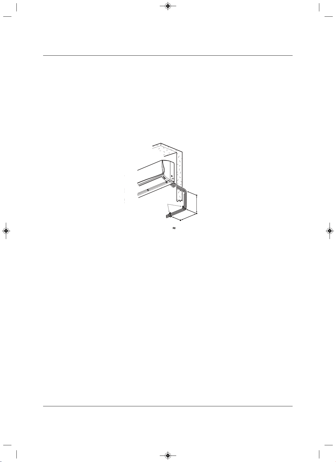
Piping
Liebert
®
SRC
™
User Manual 46
A properly-installed pipe system has sufficient supports to prevent pipes from sagging during the life of the
system. As necessary, place supports closer for segments where potential sagging could occur. Maximum
spacing of the pipe supports must meet local codes.
If local
codes do not specify pipe-support spacing, support the pipes as follows:
• Maximum of 5 feet on center for straight segments of pipe up to 3/4-in. outside diameter.
• Maximum of 6 feet on center for pipe up to 1-in. outside diameter.
• Maximum of 8 feet on
center for pipe up to 2-in. outside diameter.
Wherever the pipe changes direction, place pipe clamps within 12 inches on one side and within 12 to 19
inches of bend on the other side, as shown in Figure 5-9.
Figure 5-9 Typical pipe-su
pport location for a change in pipe di rection
A
B
Pipe
Clamps
A + B 12”–19”
MFL67502030 17. 7. 13. 오오 3:05 Page 56
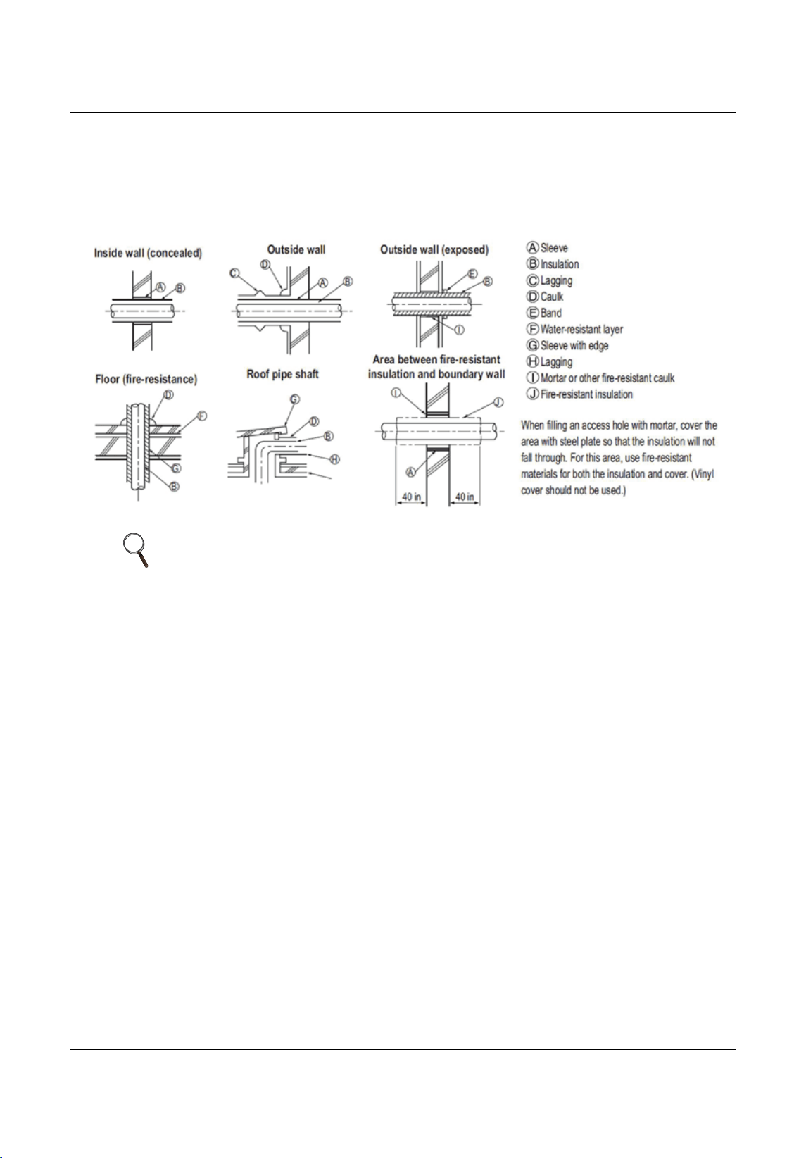
Piping
47 Liebert
®
SRC™ User Manual
5.2.12 Pipe Sleeves at Penetrations
Emerson requires that all pipe penetrations through walls, floors, and pipes buried underground be
properly-insulated and routed through an appropriate wall sleeve of sufficient size to prevent compression
of refrigerant-pipe insulation and free movement of the pipe withing the sleeve, Figure 5-
10.
Figure 5-10 Pipe sleeve options
NOTE
The diameter of the penetrations must be determined by the pipe diameter
plus the thickness of the insulation.
MFL67502030 17. 7. 13. 오오 3:05 Page 57
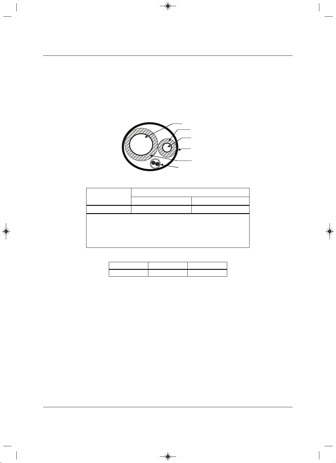
Piping
Liebert
®
SRC
™
User Manual 48
5.2.13 Underground Refrigerant Piping
Refrigerant pipe installed underground should be routed inside a vapor-tight protective sleeve to prevent
deterioration of the insulation and water infiltration. Refrigerant pipe installed inside underground casing
must be continuous without any joints. Underground refrigerant pipe must be located at a level below th
e
frost line.
Figure 5-11 shows the arrangement of refrigerant pipe and cable(s) in a conduit. Table 5-10 shows
conduit sizes for utility conduit.
Figure 5-11 Typical arrangement of pipe and cables in a utility conduit
Table 5-10 Utility-conduit sizes
Liq uid Pipe
1
Vapor Pipe
1
3/8 (1-1/8
2,3
)5/8 (2-1/8
2,4
)
3/8 (1-1/8)
3
44
1. OD pipe diameter in inches. Values in parentheses indicate O D of pipe with insulation
jacket.
2. Diameter of pipe with insulation. Thickness of pipe insulation is typical. Actual required
thickness may vary based on surrounding ambient conditions and should
be calculated
and specified by the design engineer.
3.Insulation thickness (value in parenthesis) = 3/8 inch.
4. Insulation thickness (value in parenthesis) = 1 inch.
Table 5-11 Heat-pump unit refrigerant-pipe connections (All brazed type)
Model Liq uid Conn., in. Vapor Conn., in.
SCR18, 24, 36 3/85/8
Vapor Line
Liquid Line
Min. 18 Gauge
Cable
Power/Communication
Pi
p
e Sleeve
Insulation Material
Insulation
Material
MFL67502030 17. 7. 13. 오오 3:05 Page 58
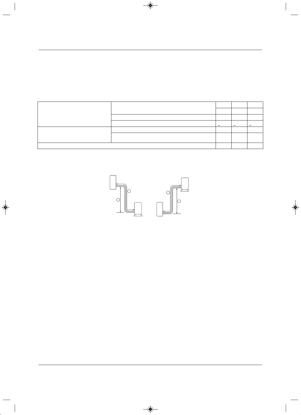
Piping
49 Liebert
®
SRC™ User Manual
5.3 Piping Connections
5.3.1 Connection Limitations
Liebert SRC systems consist of one outdoor unit and one indoor unit. One of the most critical elements of
a system is the refrigerant piping. Table5-12 lists pipe-length limits that must be followed in the design of
an SRC system.
Refer to Figure 5-12 for maximum length and elevation of piping.
Figure 5-12 System layout
Table 5-12 Refrigerant-piping system limitations
Pipe Length
(ELF = Equivalent length of pipe in feet)
Longest total equivalent piping length
SRC18 SRC24 SRC36
98.4 164.0164.0
Shortest total equivalent piping length 9.89.89.8
Distance between fittings and indoor units or outdoor units >
20 in.>20 in.>20 in.
Elevation
(All elevation limitations are measured
in actual feet.)
If outdoor unit is above indoor unit.49.2 98.4 98.4
If outdoor unit is below indoor unit.49.2 98.4 98.4
Additional refrigerant needed (oz/ft) 0.22 0.38 0.38
Outdoor unit
Indoor unit
A
B
Outdoor unit
Indoor unit
A
B
Max Length = A
Max Elevation = B
Unit = Feet
MFL67502030 17. 7. 13. 오오 3:05 Page 59

Piping
Liebert
®
SRC
™
User Manual 50
5.3.2 Piping Connections Layout
Liebert SRCs are a 1-to-1 system. There is a direct piping connection between the outdoor unit and the
indoor unit. Figure5-13 illustrates the basic pipe connections between the outdoor and indoor unit. Refer
back to this illustration as you proceed with pipe
connection. Figure5-13 shows the indoor unit installed at
a higher position than the outdoor unit. However, if you install the outdoor unit in a higher position than the
indoor units, the basic pipe connections still apply.
Refer to Table 5-12 for specific length limitations on indoor
- and outdoor-unit positioning.
Figure 5-13 Piping installation and connection overview
Figure 5-14 Pipe-support spacing for outdoors
NOTE
• As you proceed with the piping connections, be sure to adhere to the pipe-
support spacing as shown in Figure 5-14. Refer back to 5.2.11 - Pipe
Supports, for more information about using elbows, clamps and pipe-
support materials.
• Always follow state and local codes for piping and accurate support-
spacing along the outdoor pipe line.
Vinyl tape (Wide)
a
Saddle
A
B
Pipe
Clamps
A + B 12”–19”
MFL67502030 17. 7. 13. 오오 3:05 Page 60
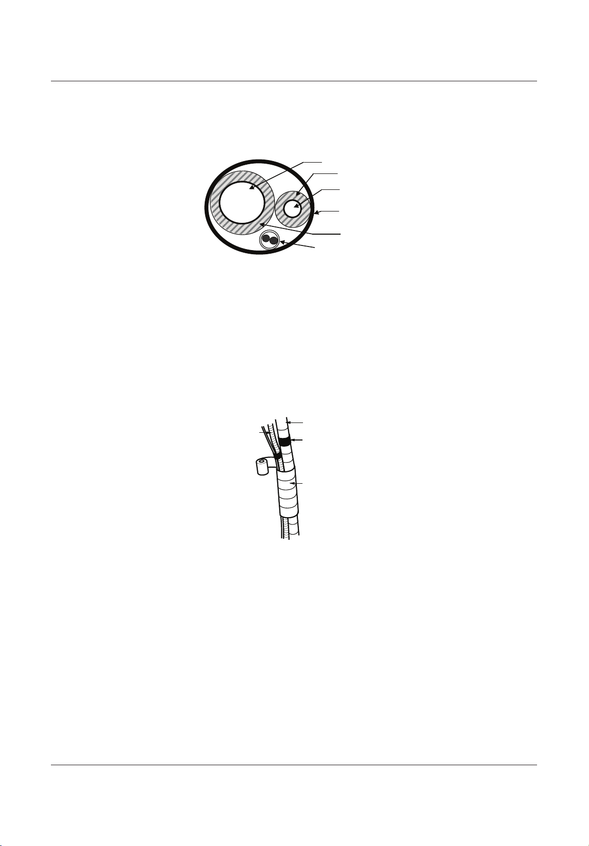
Piping
trebeiL15
®
SRC™ User Manua
l
5.3.2.1 Pipe bundling
Refer to Figure 5-15 for proper cable and pipe bundling. Note the placement of the piping along with the
necessary insulation material.
Figure 5-15 Proper pipe and cable bundling—cut-away
1. Be sure to wrap each pipe with proper insulation material.
2. Secure the piping by wrapping vinyl tape vinyl tape around the pipe.
• Use narrow-size tape for wrapping the actual pipe, Figure 5-16.
3. You can include the drain hose in the bundled piping and wrap all of them together using wider vinyl
tape, Figure 5-16.
• The end of the drain-hose outlet must be routed above the ground.
Figure 5-16 Bundling and taping piping and cables
Vapor Line
Liquid Line
Min. 18 Gauge
Cable
Power/Communication
Pi
p
e Sleeve
Insulation Material
Insulation
Material
Drain hose
Vinyl tape(narrow)
Pipe
Wrap with
vinyl tape(wide)
Bundling Piping
MFL67502030 17. 7. 13. 오오 3:05 Page 61
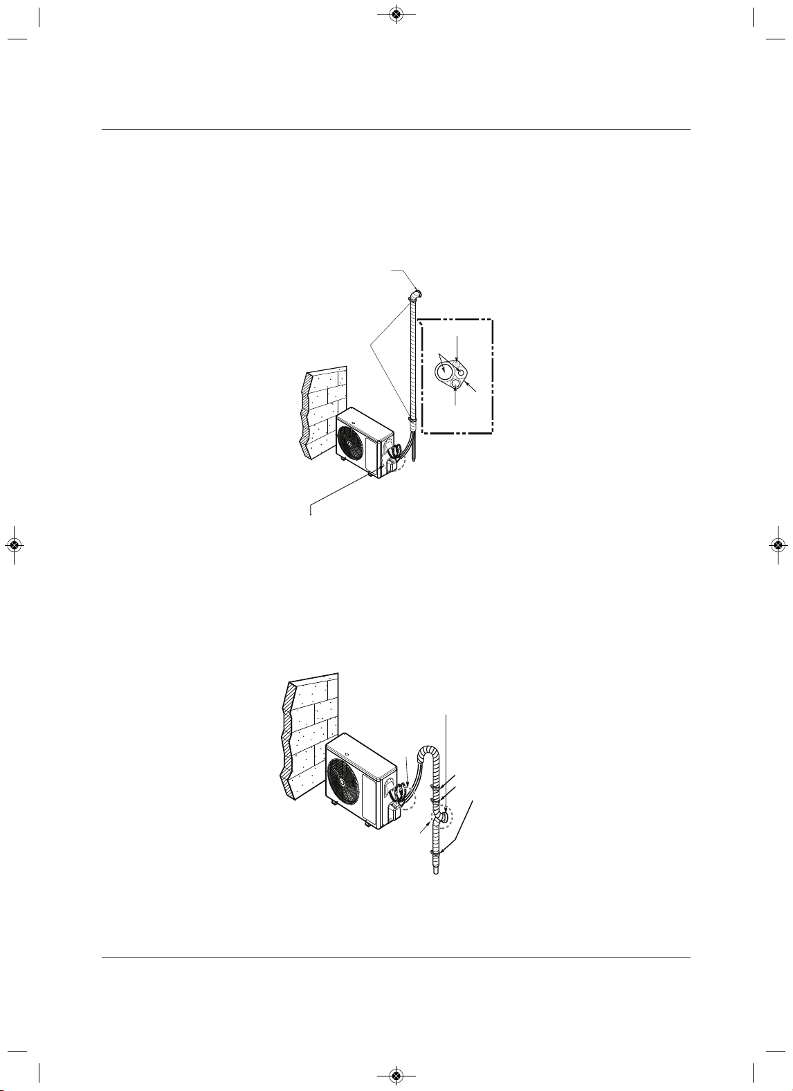
Piping
Liebert
®
SRC
™
25launaM resU
5.3.2.2 Bundling and Trap when Indoor Unit is above Outdoor Unit
1. Refer to Figure 5-17, and tape the piping, drain hose, and connection cable from down to up.
2. Secure the taped piping along the exterior wall using pipe clamps.
3. Create a trap above the electrical connections cover to prevent water from penetrating electrical
components and wiring.
Figure 5-17 Piping/Trap when indoor unit is above outdoor unit
5.3.2.3 Bundling and Trap when Indoor Unit is below Outdoor Unit
1. Refer to Figure 5-18, and tape and tape the piping, drain hose, and connection cable from down to up.
2. Secure the taped piping along the exterior wall using pipe clamps.
3. Create a trap above the electrical connections cover to prevent water from penetrating electrical
components and wiring.
Figure 5-18 Piping/Trap when indoor unit is below outdoor unit
Taping
Pipe Clamps
to Secure Pipe
Against Wall
Drain hose
Pipings
Connecting cable
Seal small openings
around pipings with a
gum type sealant.
Trap is required to prevent water
from entering into electrical parts.
Seal a small opening
around the pipings
with gum type sealant .
Trap
Trap
Pipe Clamps
to Secure Pipe
Against Wall
MFL67502030 17. 7. 13. 오오 3:05 Page 62
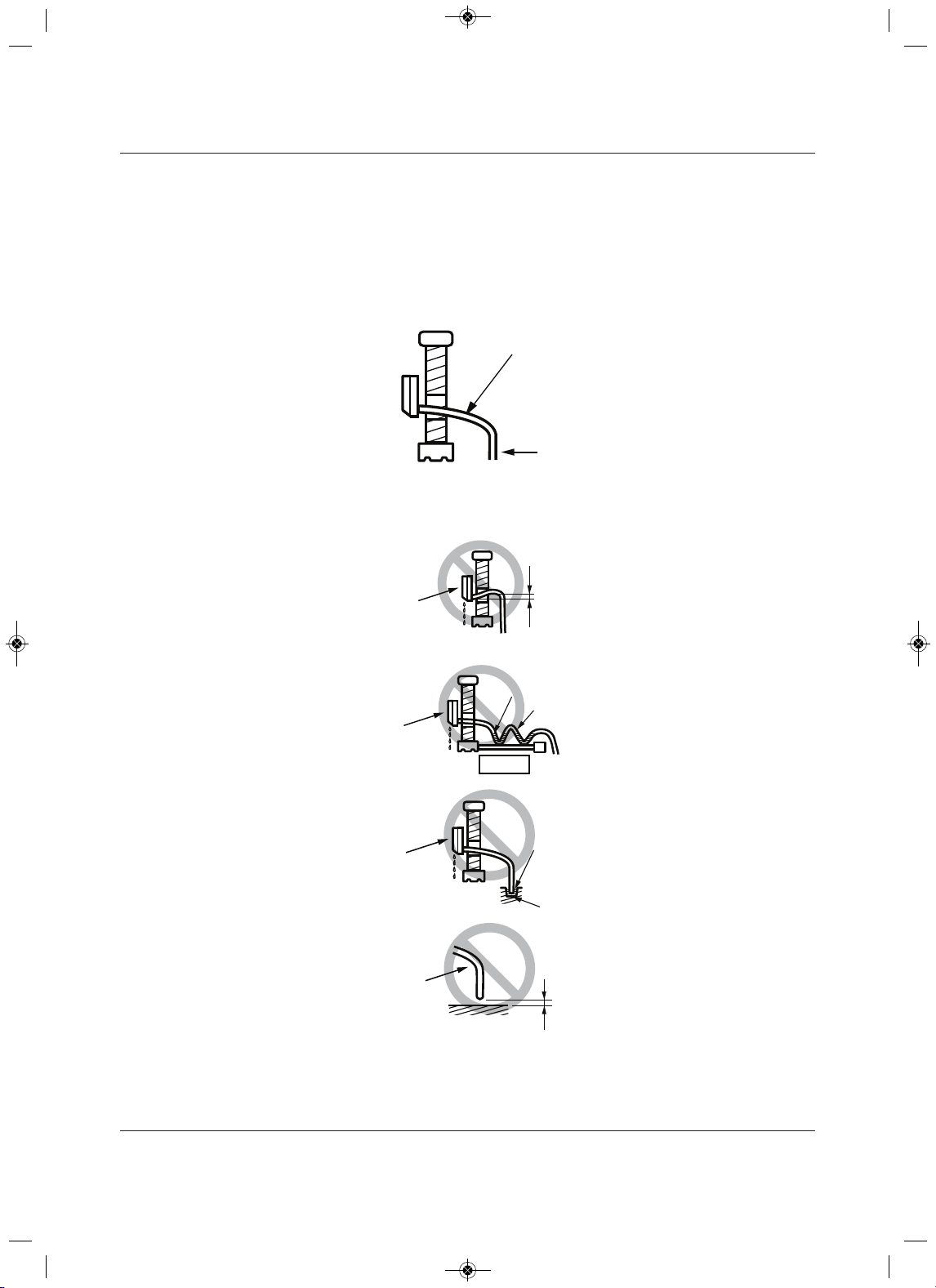
Piping
trebeiL35
®
SRC™ User Manua
l
5.3.3 Routing the Drain Hose for Indoor Unit
Drain hose is routed from the indoor unit, through the structure (wall) to the outdoors. The hose should
slope at an angle where it is higher at the indoor unit and lower at the outdoor area, letting gravity push
condensation down and out. Figure 5-19 shows the proper drainage slope. Figure 5-20 shows incorrect
methods of routing the drain hose, which cause leakage at the indoor unit.
Figure 5-19 Correct slope angle for drain hose
Figure 5-20 Incorrect methods of routing drain hose
Downward slope
to outdoor
for proper drainag
Indoor
Unit
Piping
Upward slope
to outdoor
can cause indoor
leaks.
Water
leakage
Accumulated
drain water
Air
Waving
Water
leakage
Indoor Unit
Indoor Unit
Incorr ect Drainage Setup
Tip of drain hose
dipped in water
Water
leakage
Ditch
Less than
2 Inch gap from ground
Indoor Unit
Drain Hose
MFL67502030 17. 7. 13. 오오 3:05 Page 63
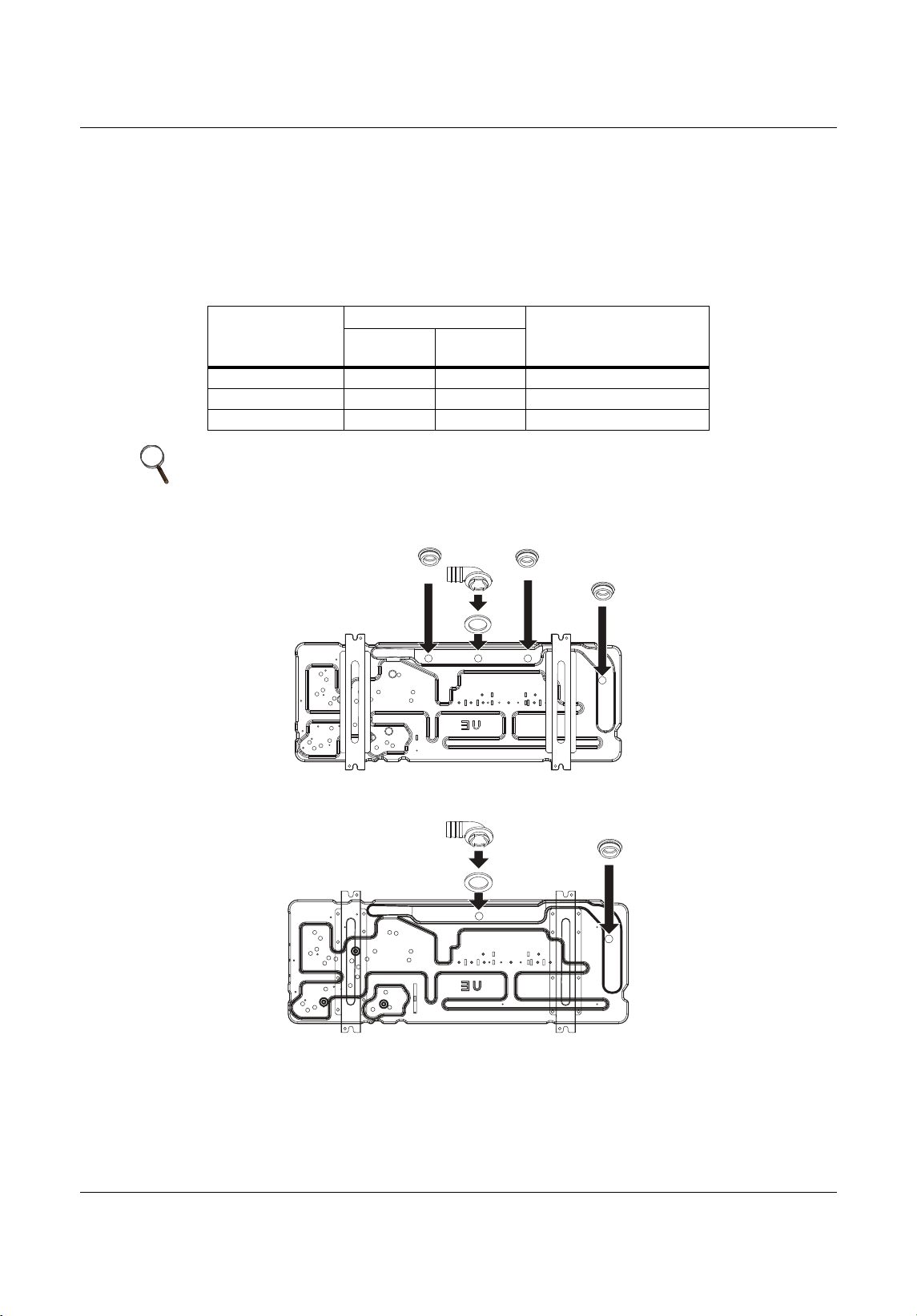
Piping
Liebert
®
SRC
™
User Manual 54
5.3.4 Installing a Drain Hose on the Outdoor Unit
Depending on the installation site, it may be necessary to install a drain plug (factory-supplied).
1. D epending on your unit model, refer to Figure 5-21 or 5-22 and to Table 5-13 for the drain-connection
components.
2. Connect a field-suppled
hose to the drain connections (A). If the hose is too long, position it carefully to
prevent kinks.
Figure 5-21 Outdoor unit drain-connection components for SRC18
Figure 5-22 Outdoor unit drain-connection components for SRC24 and SRC36
Table 5-13 Outdoor unit drain-connection components
Label
Quantity, each
ComponentSRC18
SRC24,
SRC36
A11Drain connection
B31Drain cap
C11Drain washer
NOTE
Do not use a drain hose with the outdoor unit in cold climates, otherwise the
drain water may freeze and impair heating performance.
B
B
B
A
C
B
A
C
MFL67502030 17. 7. 13. 오오 3:05 Page 64
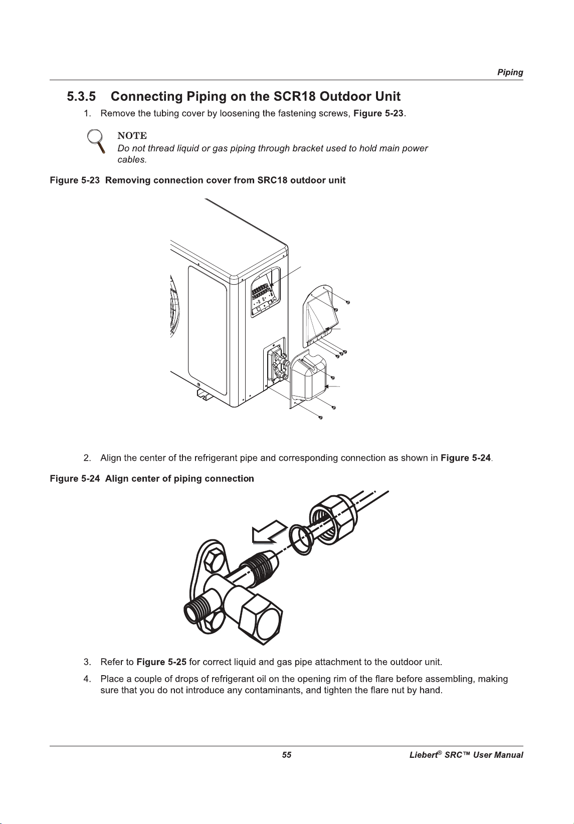
Tubing
Cover
Cover
control
Terminal Block
MFL67502030 17. 7. 13. 오오 3:05 Page 65
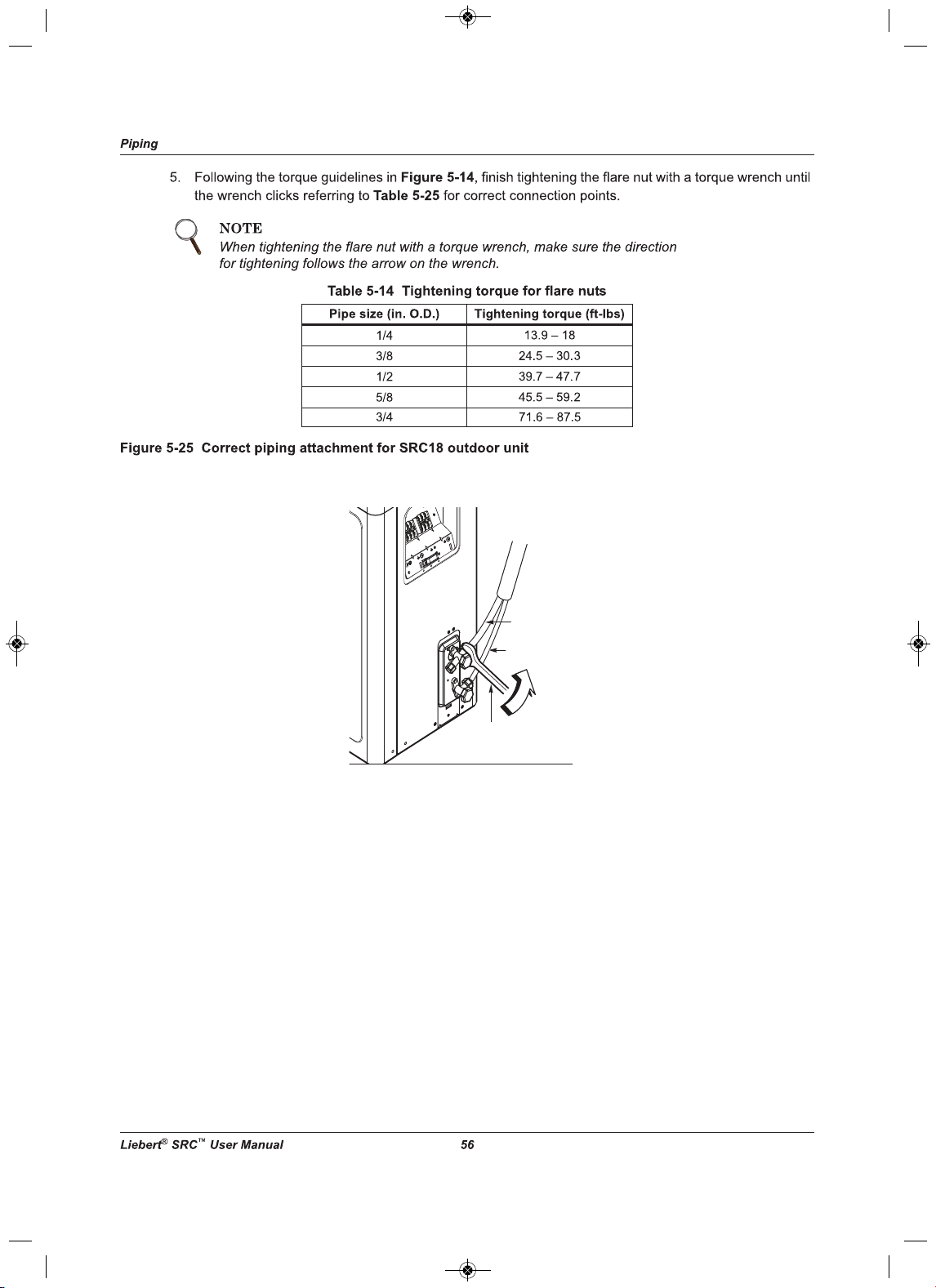
Torque wrench
Liquid side piping
(Smaller diameter)
Gas side piping
(Bigger diameter)
Outdoor unit
MFL67502030 17. 7. 13. 오오 3:05 Page 66
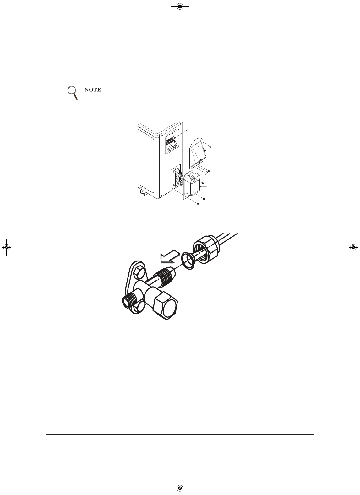
Piping
trebeiL75
®
SRC™ User Manua
l
5.3.6 Connecting Piping on the SCR24 and SCR36 Outdoor Unit
1. Remove the tubing cover by loosening the fastening screws, Figure 5-26.
Figure 5-26 Removing connection cover from SRC24 and SRC36 outdoor unit
2. Align the center of the refrigerant pipe and corresponding connection as shown in Figure 5-27.
Figure 5-27 Align center of piping connection
3. Refer to Figure 5-28 for correct liquid and gas pipe attachment to the outdoor unit.
4. Place a couple of drops of refrigerant oil on the opening rim of the flare before assembling, making
sure that you do not introduce any contaminants, and tighten the flare nut by hand.
When tightening the flare nut with a torque wrench, make sure the direction
for tightening follows the arrow on the wrench.
Tubing
Cover
Terminal
Block Cover
Cover control
MFL67502030 17. 7. 13. 오오 3:05 Page 67
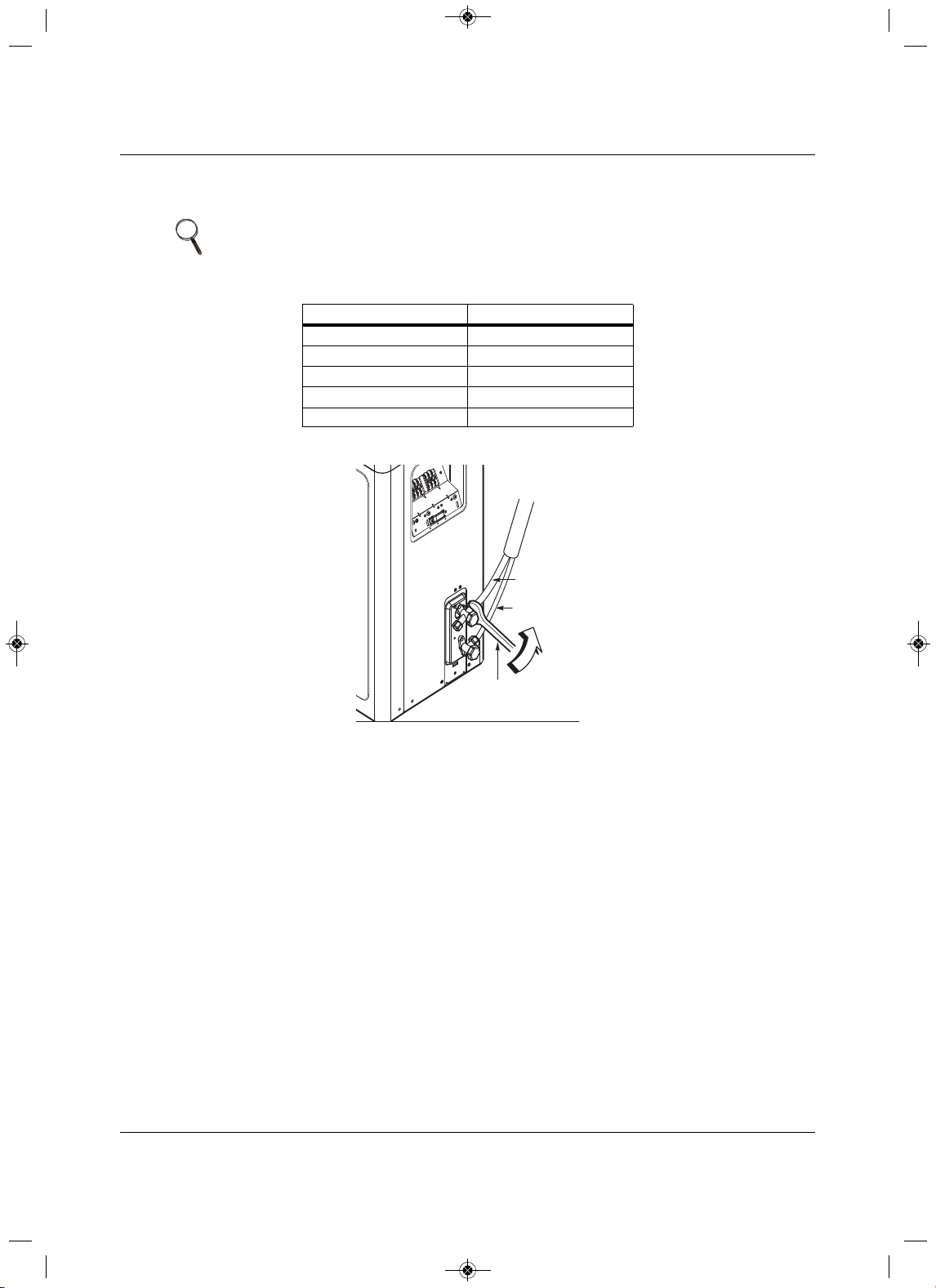
Piping
Liebert
®
SRC
™
User Manual 58
5.Following the torque guidelines in Table 5-15, finish tightening the flare nut with a torque wrench until
the wrench clicks referring to Figure 5-28 for correct connection points.
Figure 5-28 Correct piping
attachment for SRC24 and SRC36 outdoor unit
NOTE
When tightening the flare nut with a torque wrench, make sure the direction
for tightening follows the arrow on the wrench.
Table 5-15 Tightening torque for flare nuts
Pipe size (in. O.D.) Tightening torque (ft-lbs)
1/4
13.9 – 18
3/8
24.5 – 30.3
1/2
39.7 – 47.7
5/8
45.5 – 59.2
3/4 71.6 – 87.5
Torque wrench
Liquid side piping
(Smaller diameter)
Gas side piping
(Bigger diameter)
Outdoor unit
MFL67502030 17. 7. 13. 오오 3:05 Page 68
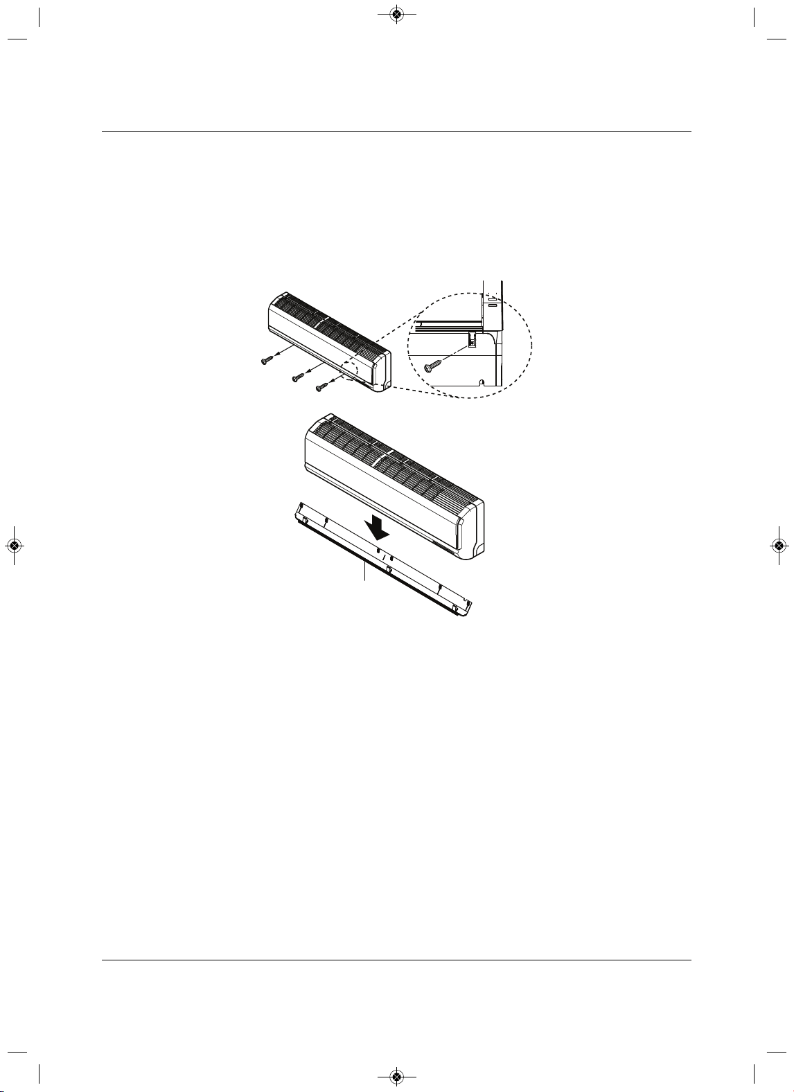
Piping
59 Liebert
®
SRC™ User Manual
5.3.7 Connecting Piping on the Indoor Unit
While following this procedure, refer to 5.3.2.1- Pipe bundling for specific bundling instructions, and to
5.3.3 - Routing the Dra in Hose for Indoor Unit for proper drainage slope during piping.
1. Pull the screw cap at the bottom of the indoor unit.
2. Unscrew
the 3 screws at the bottom of the chassis cover, Figure 5-29, and remove the chassis cover,
taking care not to scratch the main horizontal vane.
Figure 5-29 Removing the chassis cover from indoor unit
Chassis cover
MFL67502030 17. 7. 13. 오오 3:05 Page 69
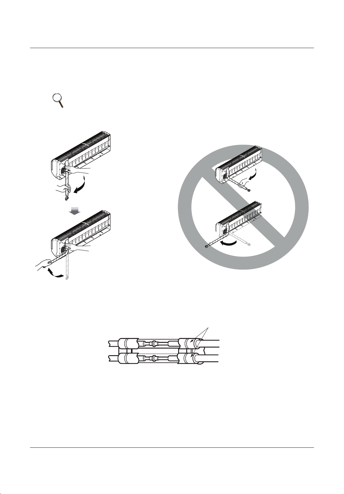
Piping
Liebert
®
SRC
™
User Manual 60
3.From the rear of the indoor unit, pull the tubing holder away from the unit as shown in Figure 5-30.
4. Remove the pipe port cover.
5. Position the tubing by unfolding the tubing and bending the tubing slowly downward first, as shown
in
Figure 5-30.
Figure 5-30 Ben ding drain tubing at rear of indoor unit
6. As shown in Figure 5-31, the fully encase the connection pipe and the indoor-unit pipe in
insulation
material by binding them together using vinyl tape. Make sure there are not gaps when binding.
Figure 5-31 Pi ping connection with insulation material
NOTE
Bending the tubing directly left or right, without bending downward first, may
cause damage.
Unfold
slowly
downward
Bend from
downward position
Insulation material
MFL67502030 17. 7. 13. 오오 3:05 Page 70
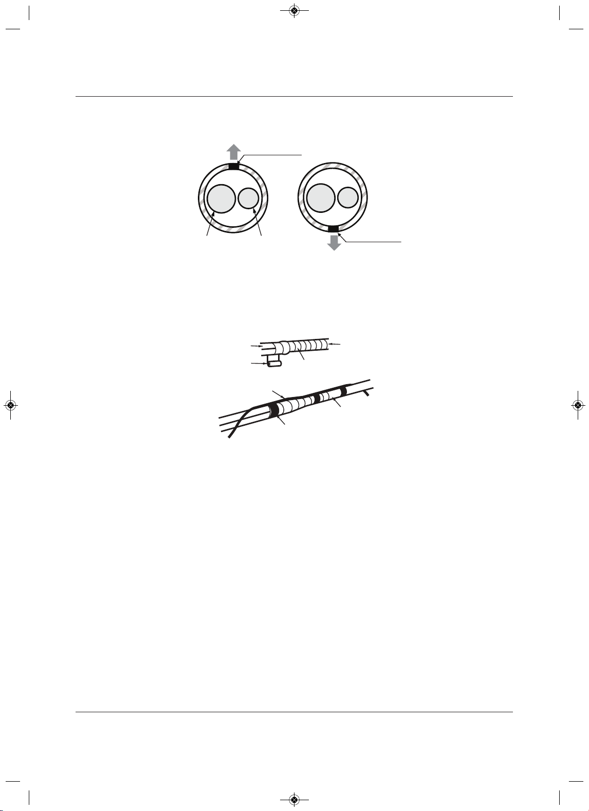
Piping
trebeiL16
®
SRC™ User Manua
l
7. Make sure the tube cutting line is placed upward, Figure 5-32.
Figure 5-32 Correct cutting line placement
8. Use narrow type vinyl tape, and make sure that the section placed in the rear pipe housing is wrapped
sufficiently.
9. Continue to wrap the indoor-unit pipe connection to the outdoor-unit as shown in Figure 5-33.
Figure 5-33 Wrapping connection pipe to indoor-unit pipe
Gas Pipe
Liquid Pipe
Cutting Line
Cutting Line
Correct Incorrect
Vinyl tape(narrow )
Connection pipe
Connecting cable
Vinyl tape (wide)
Wrap with vinyl tape
Indoor unit pipe
Pipe
MFL67502030 17. 7. 13. 오오 3:05 Page 71
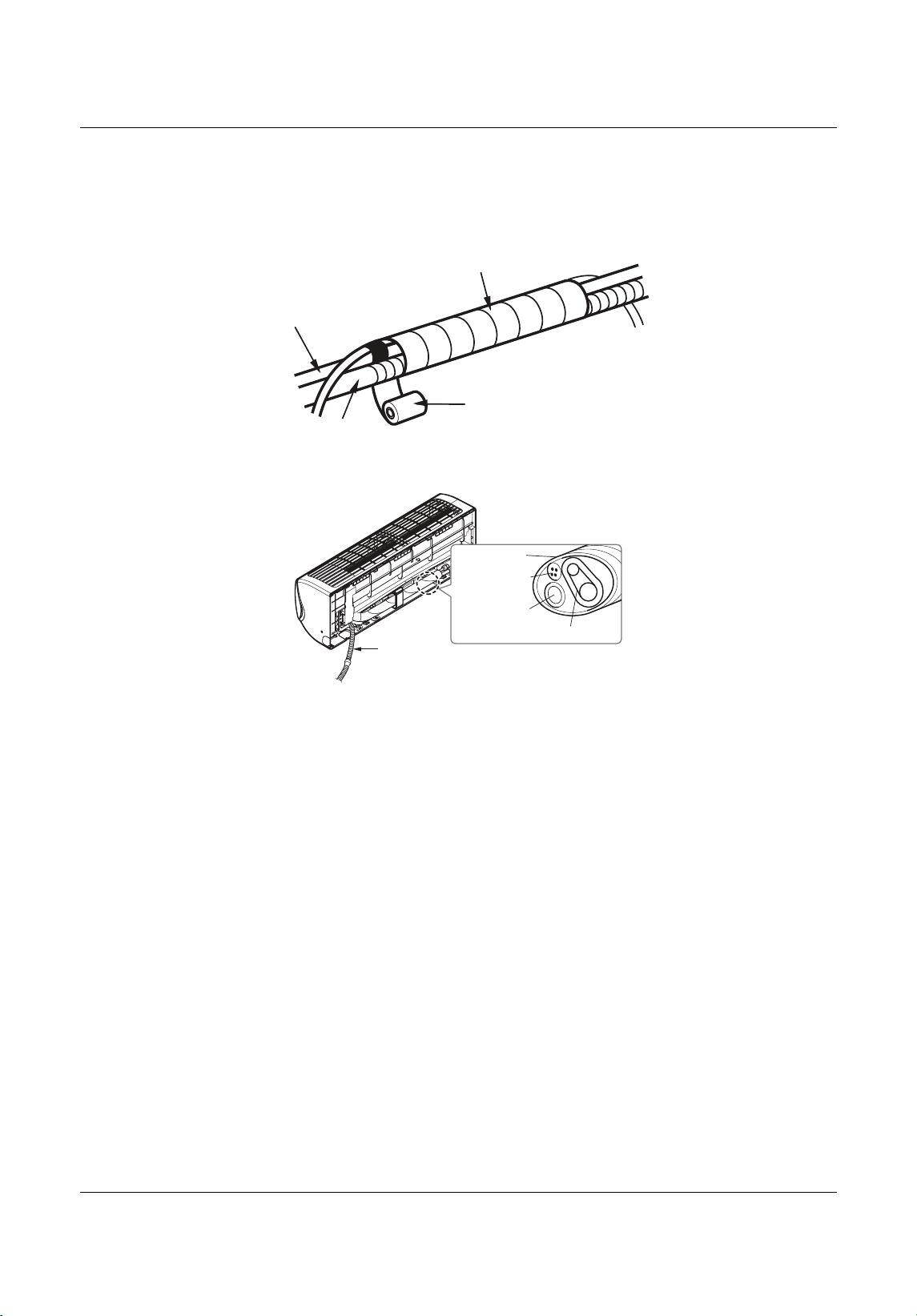
Piping
Liebert
®
SRC
™
User Manual 62
10. Using a wider vinyl tape, bundle the piping and the drain hose together, Figure 5-34.
• The tape should cover the piping and fit into the rear pipe housing on the back of the indoor unit as
shown in Figure 5-35.
Figure 5-34 Bundling pipe and drain hose at rear of indoor unit
Figure 5-35 Piping bundle placement i n housing at re
ar of indoor unit
Wrap with vinyl tape
Drain hose
Pipe
Vinyl tape(wide)
Drain hose
Connecting pipe
Connecting
cable
Tape
Drain hose
MFL67502030 17. 7. 13. 오오 3:05 Page 72
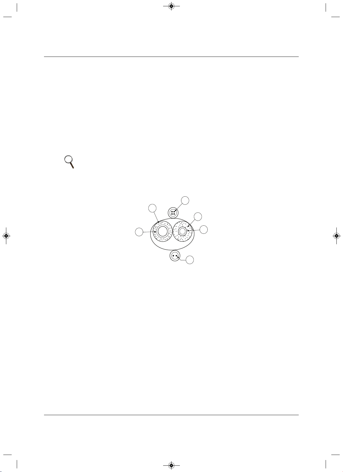
Piping
63 Liebert
®
SRC™ User Manual
5.4 Piping Insulation
To prevent heat loss/heat gain through the refrigerant piping, all refrigerant piping, including liquid lines and
vapor lines, must be insulated separately. Insulation must be a minimum 1/2-in. thick, and the thickness
may need to be increased based on ambient conditions
and local codes. All refrigerant piping, including
field-supplied isolation ball valves, service valves, and elbows must be completely insulated using closed-
cell pipe insulation. All insulation join ts must be glued with no air gaps. Insul
ation material must fit snugly
against the refrigerations pipe with now space between it and the pipe. Insulation passing through pipe
hangers, inside conduit, and/or sleeves must not be compressed. Protect insulation inside hangers and
supports with a second layer. All pipe insulation exposed
to direct sunlight and deterioration-producing
elements must be properly protected with a PVC-aluminum vapor-barrier jacket, or placed in a weather-
resistant enclosure such as a pipe rack with a top cover. The design engineer should perform calculations
to determine if the factory-supplied insulation jackets have sufficient thickness to meet local codes and to
void sweating at job-site conditions. Maximum refrigerant-pipe temperature is 227°F. Minimum refrigerant-
pipe temperature is –4°F. Add additional insulation if necessary.
Figure 5-3
6 Typical pipe-ins u lation, power wire, and communications-cable arrangement
NOTE
• Do not insulate gas and liquid pipes together as this can result in pipe
leakage and malfunction due to extreme temperature fluctuations.
• Be sure to fully insulate the piping connections.
Liquid Pipe
Communication Cables
Gas Pipe
Power Wiring
Insulation
A
B
C
D
E
E
D
D
B
A
C
MFL67502030 17. 7. 13. 오오 3:05 Page 73
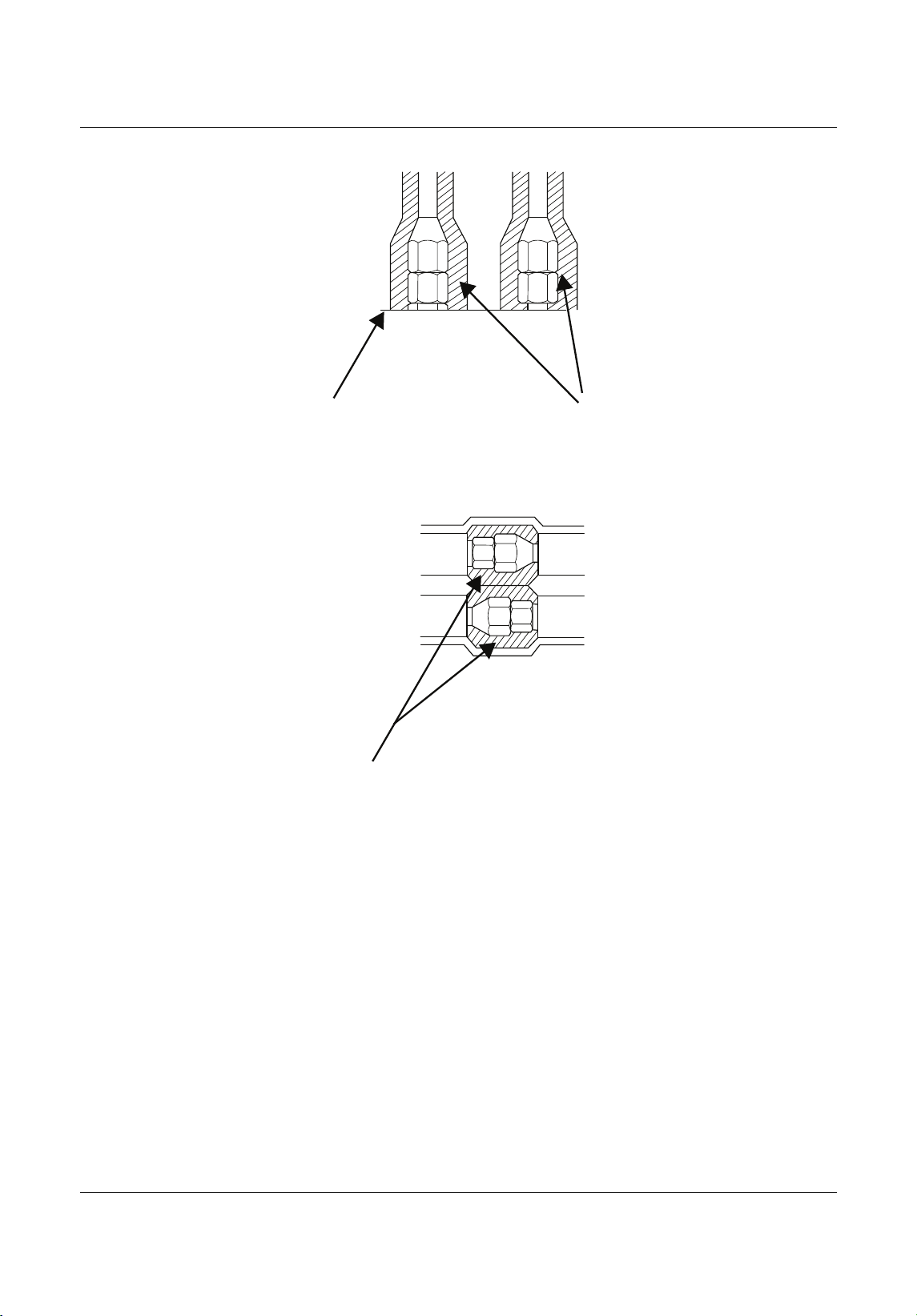
Piping
Liebert
®
SRC
™
User Manual 64
Figure 5-37 Typical butt-joint insulation at indoor unit
Figure 5-38 Typ ical refrigerant flare-fitting insulation
Surface of
Indoor Unit Casing
Field-Provided
Pipe Insulation
Field-Provided
Pipe Insulation
MFL67502030 17. 7. 13. 오오 3:05 Page 74
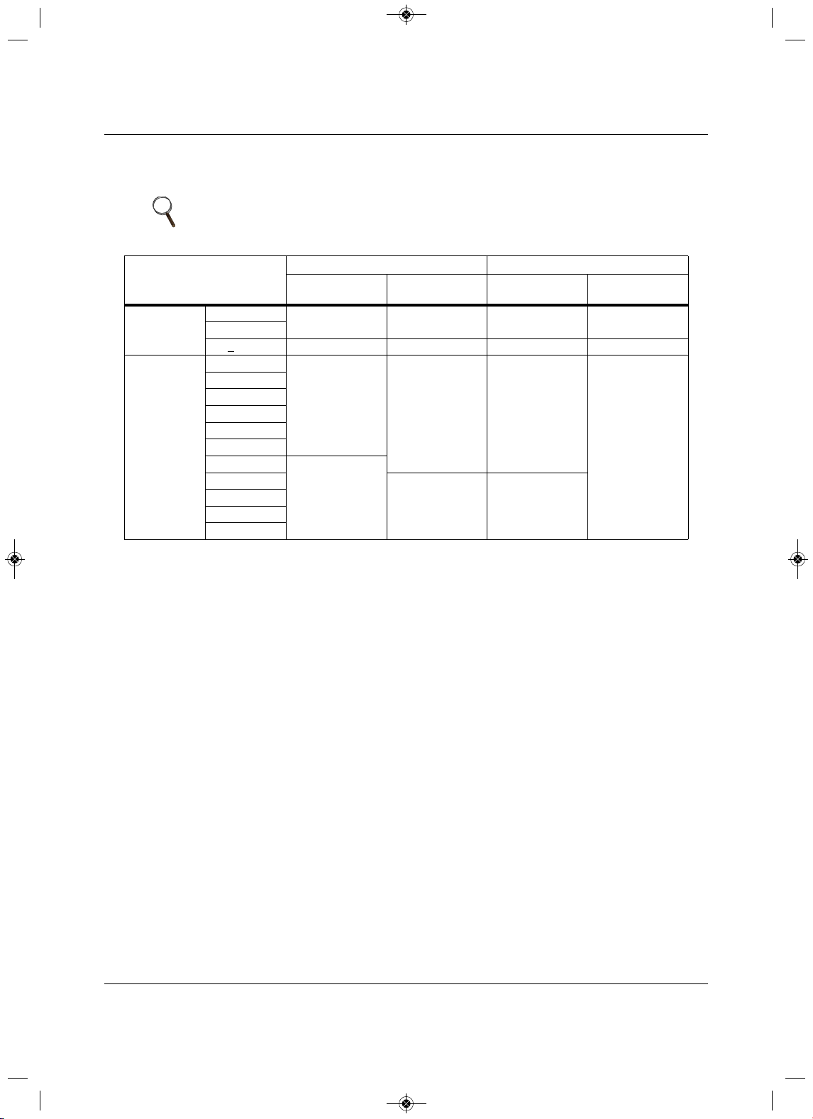
Piping
65 Liebert
®
SRC™ User Manual
5.4.1 Minimum Requirements for Wall Thickness
of Ethylene Propylene Diene Methylene (EPDM) Pipe Insulation
1. Typical location (air-conditioned): When the piping passes through and indoor area where the indoor
unit operates.
• Apartment, classroom, office, mall, hospital, etc.
2. Specia l location (air-conditioned):
a. When the location is air-conditioned, but there is severe temperature/humidity difference due
to
high ceilings.
• Church, auditorium, theater, lobby, etc.
b. When the location is air-conditioned, but internal temperature/humidity are high.
• Bathroom, swimming pool, locker room, etc.
3. Typical location (non air-conditioned): When the piping passes through an indoor area where
the
indoor unit does not operate.
•Hallway, dormitory, school, etc.
4. Special location (non air-conditioned): If the following conditions are present:
a. When the piping passes through an indoor area where the indoor unit does not operate.
b. When the humidity is high and
there is no air flow in the location where the piping is installed.
• The thickness of the above insulation material is based on heat conductivity of 0.61
Btu/in/h/ft
2
/°F.
NOTE
Follow local codes when selecting EPDM insulation wall thickness.
Table 5-16 Insulation guidelines for typical and special circumstances
Classification
Air-conditioned location Non-air-conditioned location
1. Typical
location
2. Special
location
3. Typical
location
4. Special
location
Liquid pipe
1/4 in.
1/2 in. 1/2 in. 1/2 in. 1/2 in.
3/8 in.
>
1/2 in. 1/2 in. 1/2 in. 1/2 in. 1/2 in.
Vapor
3/8 in.
1/2 in.
3/4 in. 3/4 in.
1 in.
1/2 in.
5/8 in.
3/4 in.
7/8 in.
1 in.
1-1/8 in.
3/4 in.
1-1/4
1 in.
1 in.
1-3/8 in.
1-1/2 in.
1-3/4 in.
MFL67502030 17. 7. 13. 오오 3:05 Page 75
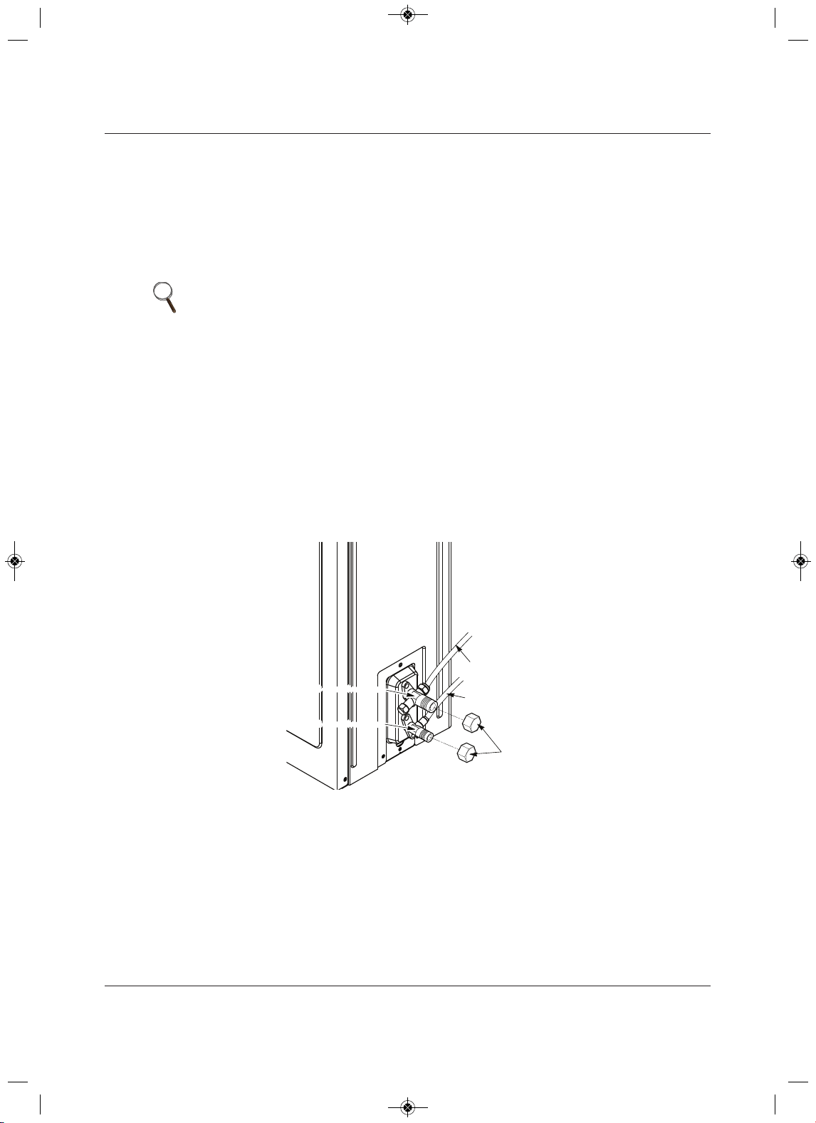
Piping
Liebert
®
SRC
™
66launaM resU
5.5 Air Purging
Air purging is performed after all piping is connected between the indoor and the outdoor unit. This step is
necessary to be sure that air refrigerant can flow through the system without the danger of leakage or
pressure issues. Air and moisture that is left in the ping can lead to undesirable results and can cause
damage to the working unit. it is important to go through a complete air-purging cycle to be sure that the
lines are cleared out. Note that you may have to repeat this process if any air or moisture is found to
remain in the piping. After air purging and evacuating the lines, be sure do a leak test for all piping and
tubing.
1. Verify that each set of pipes (liquid and gas) are properly connected between the indoor and outdoor
unit.
2. Verify that all wiring for a test run is complete.
3. Remove the service-valve caps from the gas and liquid valves at the outdoor unit, Figure 5-39.
• Keep both liquid and gas service valves closed at this step.
Figure 5-39 Removing service-valve caps from outdoor unit for purging
NOTE
Insufficient or incorrectly-performed air purging may lead to the following:
• Pressure in the system can rise.
• Operating current can rise.
• Cooling or heating efficiency falls.
• Moisture in the refrigerant circuit may freeze and block capillary tubing.
• Water can lead to corrosion of parts in the system.
Evacuation
Outdoor Unit
Gas side
Liquid side
Valve
Caps
2-way valve(Close)
3-way valve(Close)
2-way valve(Close)
3-way valve(Close)
MFL67502030 17. 7. 13. 오오 3:05 Page 76
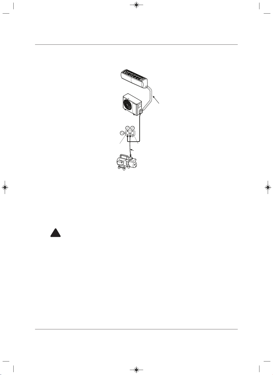
Piping
trebeiL76
®
SRC™ User Manua
l
4. Set-up the purging-hose connections, Figure 5-40.
Figure 5-40 Evacuation set up
5. Do a leak test per 5.5.1 - Piping Leak Test.
• A successful leak test must be completed before beginning evacuation.
6. Refer to 5.5.2 - Evacuation to complete the purge process.
5.5.1 Piping Leak Test
Perform the leak test by pressurizing nitrogen gas to 550 psi on both the liquid and gas pipes. Test with the
piping service valves closed. if the pressure does not drop for 24 hours, the system passes the test. It the
pressure drops, there is a nitrogen leak in the system. Find the leak, repair it, and test again.
!
WARNING
Risk of using combustible gases. Can cause explosion and fire resulting in building and equipment
damage, serious injury or death.
Do not use combustible gases, including oxygen for leak detection. Use only inert gas (nitrogen)
when checking plumbing leaks, cleaning or repairing pipes, etc.
Outdoor Unit
Lo Hi
Manifold Valve
Vacuum Pump
Charge Hose
Pressure
Gauge
Lo=Open
Hi=Close
Indoor Unit
Piping Bundle
MFL67502030 17. 7. 13. 오오 3:05 Page 77
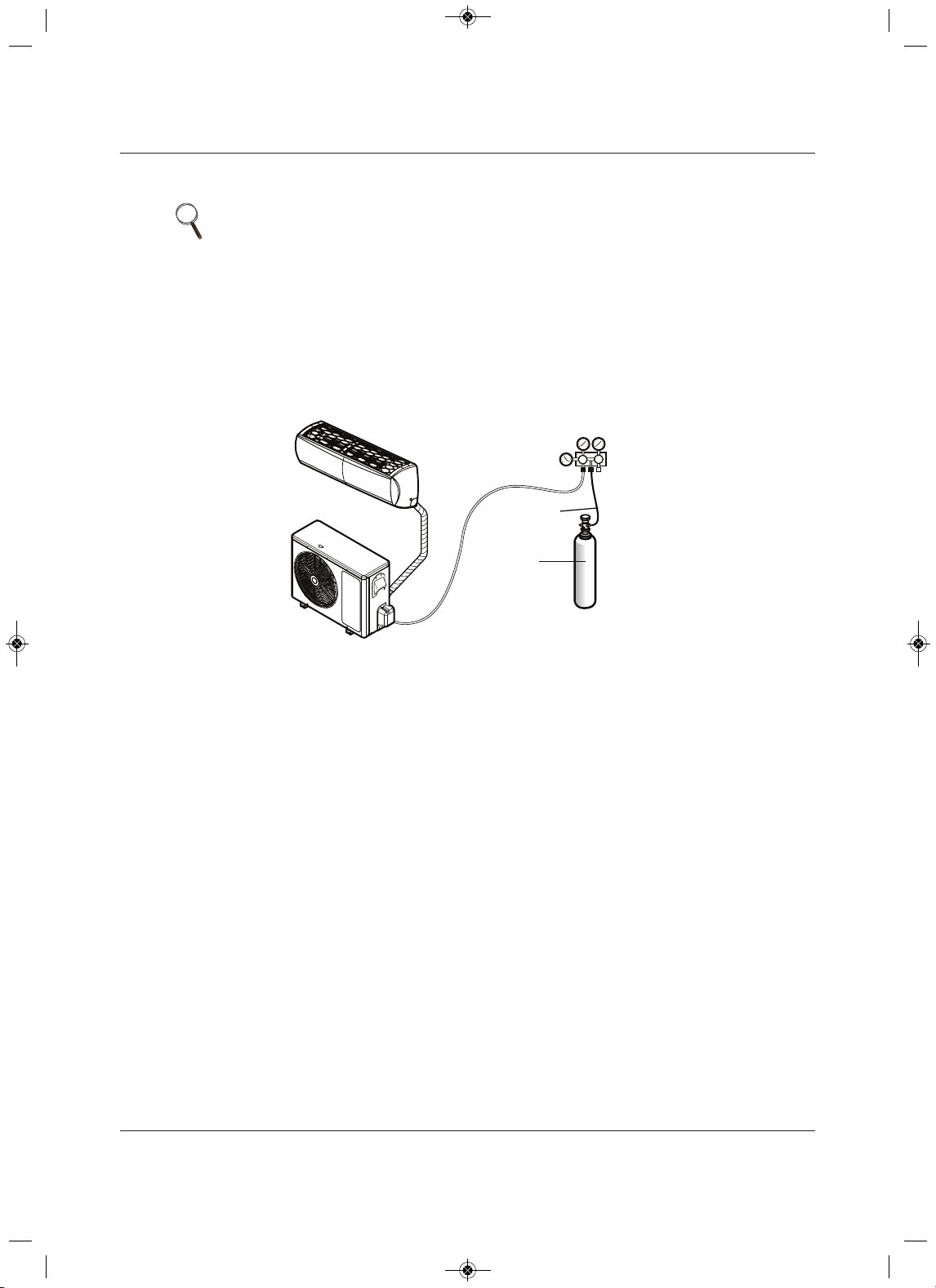
Piping
Liebert
®
SRC
™
86launaM resU
5.5.1.1 Connecting the pressure gauge
1. Connect the manifold valve (which includes the pressure gages) and the dry-nitrogen gas cylinder to
the services valves using a charge hose, Figure 5-41.
2. Pressurize the system to maximum 550 psig with dry-nitrogen gas and close the cylinder valve when
the gauge reaches 550 psig.
Figure 5-41 Leak-test set-up diagram
5.5.1.2 Soap-and-Water Leak Testing
1. Remove the caps from the 2-way and 3-way valves, Figure 5-39.
2. Open the 2-way valve by turning the valve stem counter-clockwise approximately 90 degrees, wait for
2 to 3 seconds, and close it.
3. While running nitrogen pressure, apply a soapy-water or liquid, neutral detergent on the indoor or
outdoor unit connections using a soft brush, and observe the connections for any leaks.
• Bubbles at connection points or joints indicate a leak.
4. Make a note of any leaks along the liquid and gas piping.
5. Disengage the nitrogen pressure by loosening the charge hose at the cylinder, Figure 5-41.
6. When pressure returns to normal, disconnect the charge hose from the cylinder.
7. Make repairs to all connections and piping where leaks were observed.
8. When repairs are complete, repeat the leak test using nitrogen pressure and check for further leaks.
9. Once the piping system is leak-free, proceed to 5.5.2 - Evacuation.
NOTE
• To avoid nitrogen entering the refrigerant system in a liquid state, the top of
the cylinder must be higher than its bottom when you pressurize the
system.
• Be sure the cylinder is used in a vertical standing position.
Lo Hi
Outdoor Unit
Manifold Valve
Charge Hose
Nitrogen Gas
Tank (Upright
Position)
Pressure
Gauge
Indoor Unit
Piping Bundle
MFL67502030 17. 7. 13. 오오 3:05 Page 78
Piping
69 Liebert
®
SRC™ User Manual
5.5.1.3 Ambient Temperature for Leak Test
If the ambient temperature changed between the time when the pressure was applied and when the
pressure-drop was checked, adjust the results by factoring-in approximately 1.45 psi for each 2°F of
temperature difference.
Correction formula = (Ambient temperature when pressure was appl
ied – Ambient temperature when
pressure drop was checked) x 0.01.
For example:
When pressure (550 psig) was applied, the ambient temperature was 80.6°F. When the pressure drop was
checked 24 hours later (540 psi), the ambient temperature was 68°F.
Therefore
, 80.6 – 68 x 0.01 = 0.126. In this case, the pressure drop of 0.126 was due to temperature
difference, and there is no leak in the refrigerant-piping system.
5.5.2 Evacuation
After successfully completing leak testing, use the same hook-up described in Figure 5-40, page 67, to
perform the evacuation procedure.
1. C onfirm that the “Lo” knob of the manifold valve is open, Figure 5-40, page 67.
2. Confirm that the “Hi”
know of the manifold valve is closed.
3. Run the vacuum pump until the system is evacuated down to 300 microns, and continue to run the
pump an additional 15 minutes.
4. When appropriate time has elapsed, turn-off the pump and leave the connections
secured on the
service valves for 5 minutes.
5.If the system fails to hold 500 microns or less, check a ll connections for a tight fit and repeat the
evacuation steps.
6. When the correct vacuum is reached, close the “Lo” know of the
manifold valve and stop the vacuum
pump.
NOTE
• Be sure to use a manifold valve for air purging. If it is not available, use a
stop valve.
• Be sure that the knob of the 3-way valve is always kept closed.
NOTE
The duration of running the vacuum pump will vary according to pipe length
and pump capacity. Refer to Table 5-17 for accurate time duration.
Table 5-17 Evacuation timing*
Tubing less than 33 ft. Tubing more than 33 ft.
10 minutes or more 15 minutes or more
* Required time for evacuation when 30-gal/h vacuum pump is used.
MFL67502030 17. 7. 13. 오오 3:05 Page 79
Piping
Liebert
®
SRC
™
User Manual 70
5.5.3 Removing Purge and Test Equipment
When evacuation is completed, turn-off all valves a t the outdoor unit and safely disengage the manifold
valve and vacuum pump using the following steps.
1. Using a wrench, turn the valve of the liquid stem counter-clockwise to fu
lly open the valve, Figure 5-
40, page 67.
2. Turn the valve of the gas temp counter-clockwise to fully open the valve.
3. Loosen the charge hose connected to the gas-side service port slightly to release the pressure, and
remove the
hose.
4. Replace the flare nut and its cap on the gas service port, and fasten the flare nut securely using an
adjustable wrench.
• This step is very important to prevent leakage from the system.
5. Replace the valve caps at both
gas- and liquid-side service valves and fasten them tightly.
MFL67502030 17. 7. 13. 오오 3:05 Page 80
Electrical Connections
71 Liebert
®
SRC™ User Manual
6.0 Electrical Connections
!
WARNING
Arc flash and electric shock hazard. Can cause serious injury or death. Open all local and remote
electric power disconnect switches, verify with a voltmeter that power is off and wear personal
protective equipment per NFPA 70E before working within the
electric control enclosure.
• All electric wiring and communication cable work must be performed by a licensed electrician
and conform to all applicable national, state and local electrical codes and the instructions in this
manual.
• Undersized wiring may lead to unacceptab
le voltage at the unit and may cause unit malfunction
and be a fire hazard.
• Properly ground the Liebert SRC indoor and outdoor unit. Ground wiring is required to prevent
accidental electrical shock during current leakage.
•Ground wiring must always
be installed by a qualified technician.
• Do not connect ground wire to refrigerant, gas or water piping, to lightning rods, to telephone
ground wiring, or to the building plumbing system. Failure to properly provide a National
Electrical Code-approved
earth ground can result in electric shock, physical injury or death.
•Install properly-sized breakers/fuses/overcurrent-protection switches and wiring in accordance
with local, state, and National Electrical Code regulations related to electrical equipment and
wiring, and foll
owing the instructions in this manual. Using an oversized breaker or fuse may
result in electric shock, physical injury or death.
• Replace and securely fasten all control box and panel covers immediately after working on the
unit to protect the operator from
the hazards above.
NOTE
• Consider ambient conditions (temperature, direct sunlight, inclement
weather, etc.) when selecting, installing, and connecting the power wiring.
• Properly ground the indoor and outdoor unit. Improperly installed ground
wire can cause communication problems from electrical noise and motor-
current leakage. Ground wiring must always be installed by a qualified
technician.
• If the system operates in reversed phase, it may damage the compressors
or other components.
• If there is a possibility of reversed phase, phase loss, momentary blackout,
or the power goes on and off while the system is operating, install a field-
supplied phase-loss protection circuit.
• Do not connect ground wire to refrigerant, gas or water piping, to lightning
rods, to telephone ground wiring, or to the building plumbing system.
Failure to properly provide a National Electric Code-approved earth ground
can result in property damage and equipment malfunction.
• Install appropriately-sized breakers/fuses/overcurrent-protections switches
and wiring in accordance with local, state, and National Electric Code
regulations related to electrical equipment and wiring, and following the
instructions in this manual. Using an oversized breaker or fuse may result
in equipment malfunction and property damage.
MFL67502030 17. 7. 13. 오오 3:05 Page 81
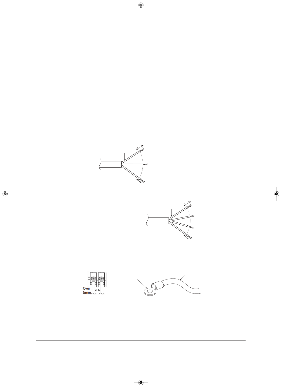
Electrical Connections
Liebert
®
SRC
™
27launaM resU
6.1 Power-supply/Power-wiring Specifications
• Liebert SRC systems operate at 1 , 208 – 230 V, 60 Hz.Ø
• Power-supply wire type and size should be selected based on National Electrical Code and local
codes. Maximum allowable voltage fluctuation ±10% or nameplate rated value. Refer to Figure 6-1 for
wiring guidelines.
• Properly ground the indoor and outdoor unit per National Electrical Code and local codes.
• Use only copper wiring that is stranded and shielded with the wires separately insulated.
• Ground wire should be longer than the common power/communication wires.
• Refer to the appropriate circuit and terminal-block diagrams for your model unit.
• Always match color codes of each wire and follow wiring diagram.
Figure 6-1 Indoor and Outdoor wiring and communications cable diagram
Best practice dictates using ring or spade terminals to terminate power wiring at the power terminal block,
Figure 6-2.
Figure 6-2 Typical ring terminal
6/16” ± 2/16”
13/16”
GN/YL
Power Wiring, Ground
to Outdoor Unit
Power Wiring, Ground,
Communication Cable
From Outdoor Unit
To Indoor Unit
13/16”
GN/YL
Line Voltage
(208/230V)
GN/YL = (Green, Yellow)
6/16” ± 2/16”
For 9/12K Indoor Units: AWG 14
For 18K Indoor Units: AWG 12
For 9/12/18K Indoor Units: AWG 18
Ring Terminal
Power Wiring
MFL67502030 17. 7. 13. 오오 3:05 Page 82
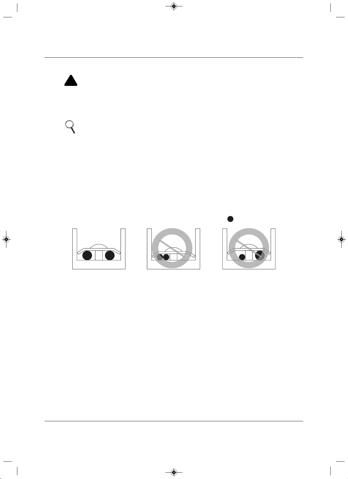
Electrical Connections
73 Liebert
®
SRC™ User Manual
If ring terminals or space clips are not available then:
Figure 6-3 Proper and Improper power-wiring connections
!
WARNING
Risk of improper electrical connection termination. Can cause building and equipment damage,
excessive heat at the terminations, smoke, fire, electric shock, serious injury and death.
Do not terminate different gauge wires to the power terminal block. Slack in the wiring
may
generate heat and fire.Do not ground the shield of the communications cable to the indoor unit
frame or other grounded entities of the building.
NOTE
• When terminating wires of the same thickness, follow the instructions in
Figure 6-3.
• Attach the wire securely without placing external force on the terminal
block.
• Use an appropriately-sized screwdriver to tighten the terminals.
• Do not over-tighten the connections. Over-tightening may damage the
terminals.
• Never apply line-voltage power to the communications-cable terminal
block. If contact is made, the PCBs may be damaged.
• Always include some allowance in the wiring length when terminating.
Provide some slack to facilitate removal of electrical panels when servicing.
:Copper Wire
Terminate multiple power wires of
the same gauge to both sides.
Do not terminate two wires on
one side.
Do not terminate different gauge
wires to a terminal block.
MFL67502030 17. 7. 13. 오오 3:05 Page 83
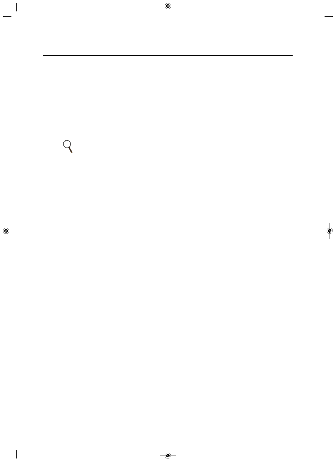
Electrical Connections
Liebert
®
SRC
™
User Manual 74
6.2 Communication-cable Specifica t ions
• Use a 4 conductor, shielded, stranded cable between the outdoor unit and the indoor unit.
• Minimum 18-gauge shielded CVVS or CPEVS cable.
•Insulation materials as required by local code.
• Rated for continuous exposure of temperatures up to 1
40°F.
• Maximum allowable cable length: 984 ft.
•Firmly attach the cable. Provide slack but secure in a way to prevent external forces from being
imparted on the terminal block.
• Terminate the cable shield to a grounded surface at the
outdoor unit only.
6.3Communication Cables between the Unit and Contr o lle r
•Field-supplied, 18 gauge, stranded 4-conductor communication cable (shielded).
• All insulation material as recommended by local code.
• Starting at the outdoor unit, terminate the cable on terminals Internet A and Internet B. Route the cable
as needed between each
device.
NOTE
• Always verify that the communication cable is connected to a
communications terminal on the unit. Never apply line-voltage power to the
communication-cable connection. If contact is made, PCBs may be
damaged.
• The shield of the communication cable connecting the outdoor unit to the
indoor unit should be grounded only to the outdoor-unit frame.
• Tie the shield of each cable segment together using a wire nut at each
indoor unit. Maintain polarity through the communication network.
• Never use a common multiple-core communication cable. Each
communications bus must be provided a separate cable (that is, between
the outdoor unit and indoor unit).
MFL67502030 17. 7. 13. 오오 3:05 Page 84
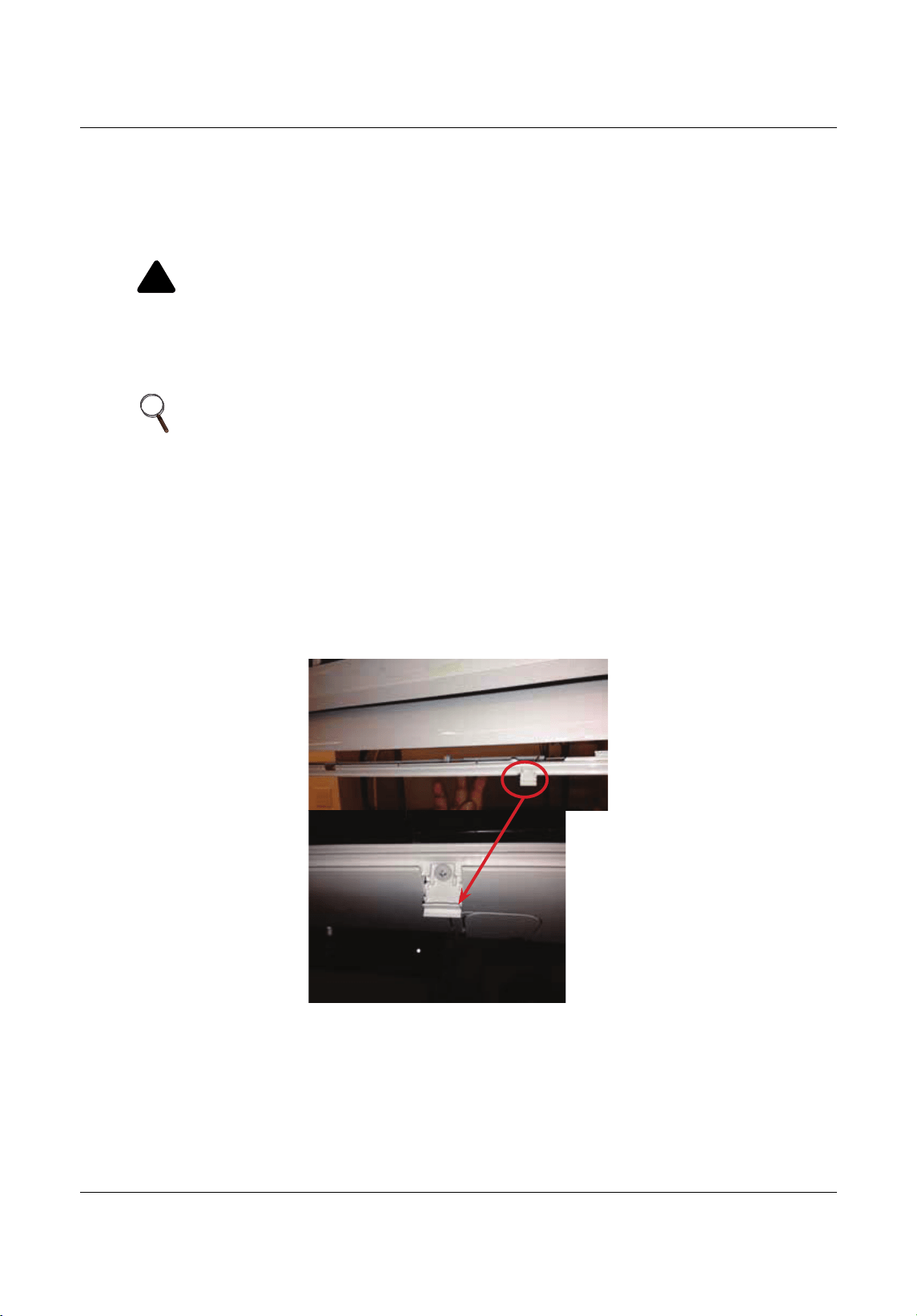
Electrical Connections
75 Liebert
®
SRC™ User Manual
6.4 Connecting Indoor Unit Electrical Wiring
The general guidelines for connecting electrical and communication cables to the indoor unit are the same
for each system. However, the actual connections on the terminal block will differ. Refer to the figures for
the model that you are wiring for correct contact on each
terminal block. Depending on your indoor unit, the
location of the terminal block may vary slightly from the images shown in this section.
1. At the bottom panel of the indoor units, un-snap the latches that cover the Phillips screw heads,
Figu
re 6-4.
Figure 6-4 Latch over the screws on bottom panel of indoor unit
!
WARNING
Arc flash and electric shock hazard. Can cause serious injury or death. Open all local and remote
electric power disconnect switches, verify with a voltmeter that power is off and wear personal
protective equipment per NFPA 70E before working within the
electric control enclosure or making
any electrical connections or disconnections.
Follow all safety and warning information in this manual.
NOTE
• Follow all safety and warning information outlined at the beginning and
throughout this manual. Failure to do so may cause unit failure.
• Some units may require you to remove the control cover from the terminal-
block area. Most control covers are attached with a Phillips-head screw.
• Connect the electrical cable to the indoor unit by connecting the wires to
the terminals on the control board individually according to the outdoor-unit
connection. Be sure that the color of the wires at the outdoor unit and the
terminal numbers are the same as those for the indoor unit.
MFL67502030 17. 7. 13. 오오 3:05 Page 85
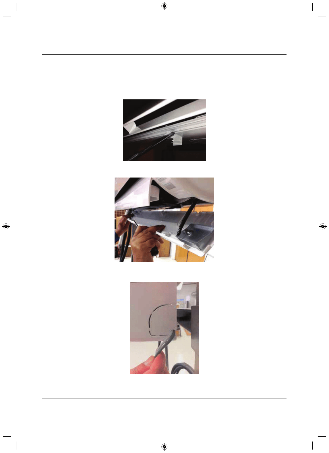
Electrical Connections
Liebert
®
SRC
™
User Manual 76
2. Using a Phillips-head screwdriver, remove the screws from the bottom panel of the indoor unit,
Figure 6-5 and set the bottom panel aside, Figure 6-6.
• The electrical/communication wiring is usually routed through the back/bottom of the indoor unit
through
a knockout panel, Figure 6-7.
Figure 6-5 Remove screws from bottom panel
Figure 6-6 R em ove bottom panel
Figure 6-7 Communication-wires
knockout panel
MFL67502030 17. 7. 13. 오오 3:05 Page 86
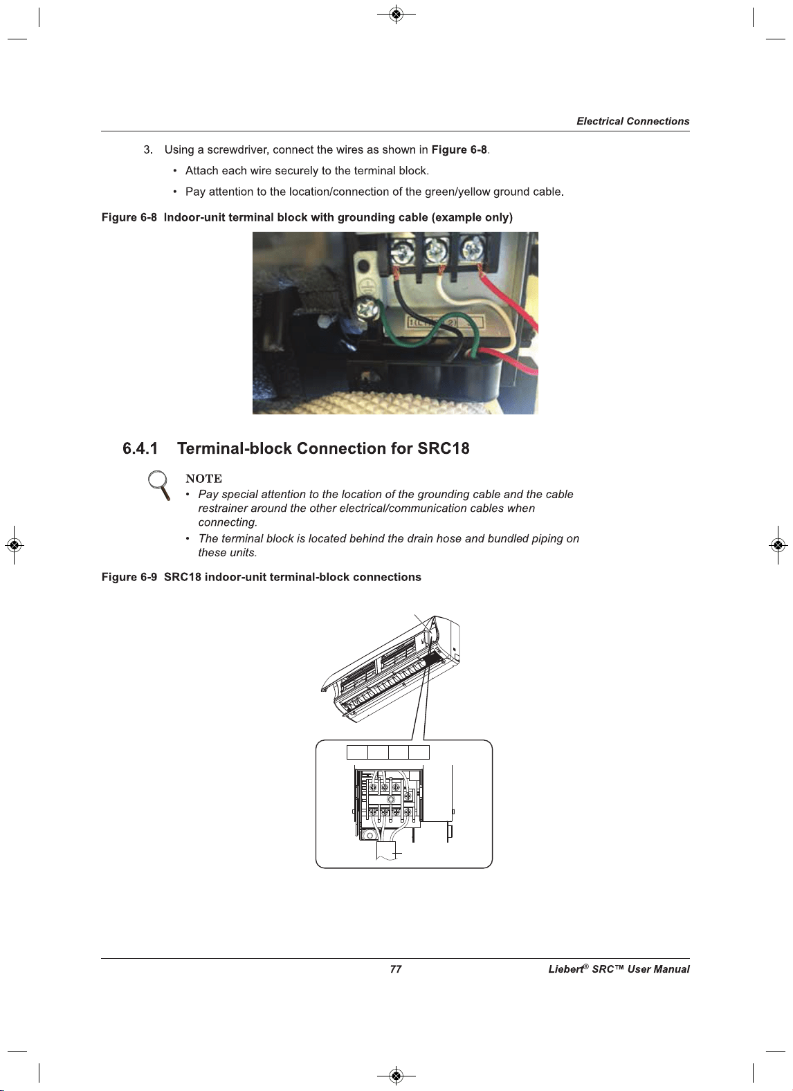
1(L1) 2(L2) 3
1(L1) 2(L2)
3
Power connecting cable
Control Cover
MFL67502030 17. 7. 13. 오오 3:05 Page 87
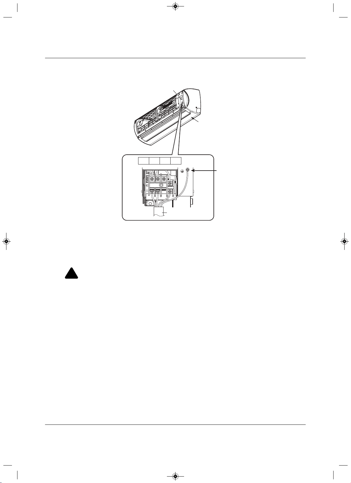
Electrical Connections
Liebert
®
SRC
™
User Manual 78
6.4.2 Terminal-block Connection for SRC24, SRC36
Figure 6-10 SRC24 and SRC36 indoor unit terminal-block connections
6.5 Connecting Outdoor Unit Electrical Wiring
The general guidelines for the electrical and communication cables to the outdoor unit are the same for
each system. However, the actual connections on the terminal block will differ. Refer to each figure for the
model you are installing for the correct wiring of
each terminal block.
1. Using a Phillips-head screwdriver, remove the conduit-panel cover from the outside of the unit.
2.Inspect all wiring inside the casing to make sure that they are secure and have not come loose during
transportation and installation.
• Loose wires
can cause the wiring to burn-out quickly.
•Inspect wires for damage or cracks (manufacturing defects).
3. Confirm that the Electrical power-supply capacity is sufficient to run the unit. Refer to the specifications
in 2.1 - Electrical Data.
4. Confirm that you are using the correct wire gauge
size to proceed.
!
WARNING
Arc flash and electric shock hazard. Can cause serious injury or death. Open all local and remote
electric power disconnect switches, verify with a voltmeter that power is off and wear personal
protective equipment per NFPA 70E before working within the
electric control enclosure or making
any electrical connections or disconnections.
•Follow all safety and warning information in this manual.
• Verify that a circuit breaker or some other emergency-power cutoff device is in place before any
power wiring is done to the s
ystem.
•Never touch any power lines or live cables before power is cut-off to the system.
•Familiarize yourself with the location of the circuit breaker.
Control Cover
Bottom Panel
Electrical Wiring
Knockout
Indoor Unit
1(L1)
2(L2)
3
1(L ) 2 (N )
3
Power Connection Cable
Grounding Cable
MFL67502030 17. 7. 13. 오오 3:05 Page 88
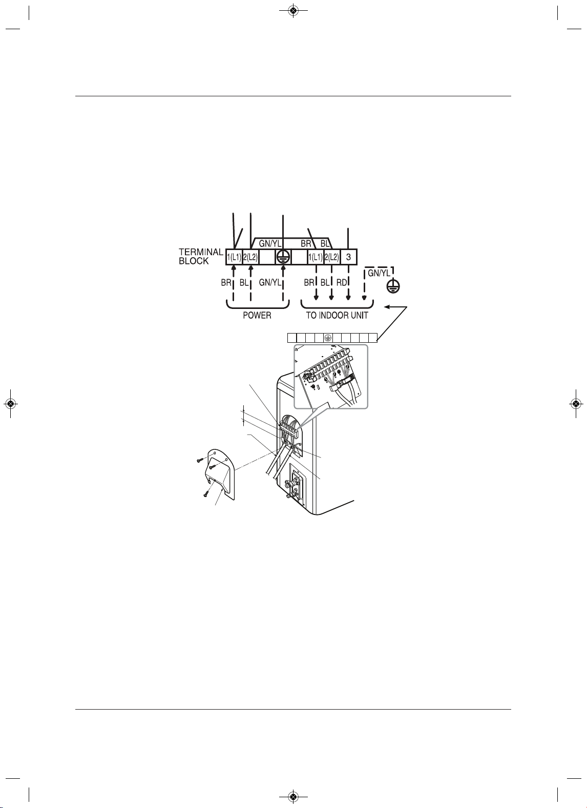
Electrical Connections
trebeiL97
®
SRC™ User Manua
l
5. Using a screwdriver, refer to Figure 6-11 or Figure 6-12, and connect the wires as follows:
• Securely attach each wire to the terminal block.
• Bundle cabling using a cable restrainer.
• Pay attention to the location/connection of the green/yellow grounding cable. In some models, the
connection is located on the side of the actual terminal block.
• Maintain a minimum of 0.2-in. of wire length from the terminal block to cable bundle.
Figure 6-11 SRC18 outdoor-unit terminal-block connections
Outdoor Unit
Terminal Block
Over 0.2”
Conduit Panel
Connection/Communication
Cable (Leading to Indoor Unit)
Power Cord
Cover control
1(L1) 2(L2) 1(L1) 2(L2 )
3
180HSV4
MFL67502030 17. 7. 13. 오오 3:05 Page 89
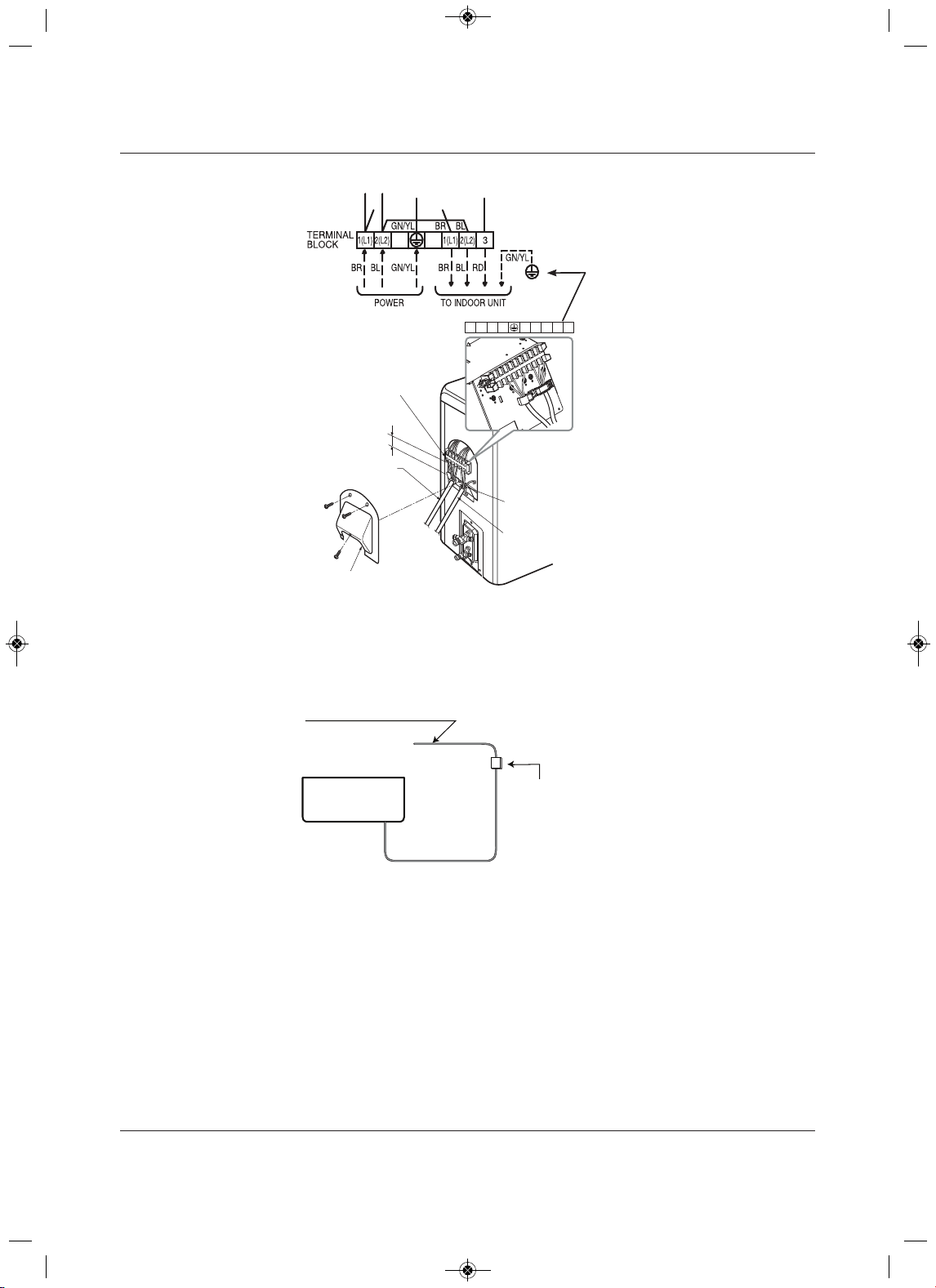
Electrical Connections
Liebert
®
SRC
™
08launaM resU
Figure 6-12 SRC24 and SRC36 outdoor-unit terminal-block connections
6. Use a recognized circuit breaker between the power source and the unit. A disconnecting device to
adequately disconnect all supply lines must be fitted.
Figure 6-13 shows an example of how a circuit breaker should be wired through the Liebert SRC system.
Figure 6-13 Circuit breaker wiring
Outdoor Unit
Terminal Block
Over 0.2”
Conduit Panel
Cover control
Connection/Communication
Cable (Leading to Indoor Unit)
Power Cord
1(L1) 2(L2) 1(L1) 2(L2)
3
Air
Conditioner
Main Power Source
Circuit Breaker
Use a circuit breaker
or time delay fuse
MFL67502030 17. 7. 13. 오오 3:05 Page 90
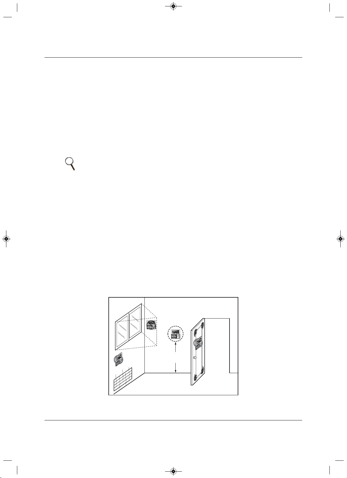
Electrical Connections
81 Liebert
®
SRC™ User Manual
6.6 Thermostat Installation and Wiring
NOTICE
Risk of improper thermostat installation. Can cause unit malfunction.
•Installation work must be performed in accordance with the national wiring standards and local
code by authorized personnel only.
•If local electric and building code requires plenum(CMP) cable, use
an enclosed, non-
combustible conduit (metal raceway) or FT-6 rated or above cable.
• When using back cable-entry, AWG#22, 3 core shielded wire is recommended.
• When using top or right-side cable entry, AWG#24, 3
core shielded wire is recommended.
• Do not bury the thermostat in the wall. This can damage the temperature sensor.
• Do not install a cable 164 ft (50 m) or longer. This can cause communication errors.
Because the room-temperature sensor is in the thermostat,
it should be installed in a place away from
direct sunlight, high humidity, and direct supply of cold air to maintain proper temperature of the space.
Install the thermostat about 5 ft. (1.5 m) above the floor in an area with good
air circulation at an average
temperature, Figure 6-14.
Do not install the thermostat where it can be affected by the following:
• Drafts or dead spots behind doors and in corners.
•Hot or cold air from ducts.
• Radiant heat from sun or appliances.
• Concealed pipes or chimneys.
• Uncontrolled areas such as on an outside wall.
The thermostat is equipped with an LCD display and should be installed at the recommended height for
proper view of the display.
Figure 6-14 Proper
and Improper thermostat locations
NOTE
If the distance between the thermostat and the indoor unit is longer than 32 ft
(10 m), use an extension cable.
5feet
(1.5meters)
Direct
Sun ray contact area
no
no
no
yes
O
p
e
r
a
t
i
o
n
u
n
i
t
Z
O
N
E
1
23
4
H
um
i
d
i
f
y
J
E
T
A
U
T
O
A
U
T
O
S
WI
N
G
O
P
E
R
A
T
I
O
N
F
A
N
S
P
E
E
D
P
r
o
g
r
a
m
s
e
t
S
U
B
F
U
N
C
T
I
O
N
S
E
T
T
E
M
P
R
o
o
m
T
e
mp
H
I
M
E
D
L
O
H
e
a
t
e
r
D
e
f
r
o
s
t
F
i
l
t
e
r
P
r
e
h
e
a
t
O
u
t
d
o
o
r
T
i
m
e
T
i
m
e
r
O
n
S
e
t
n
o
.
T
i
me
O
f
f
0
1
0
3
0
5
0
7
0
9
1
1
1
3
1
5
1
7
1
9
2
1
2
3
O
p
e
r
at
i
o
n
u
n
i
t
Z
O
N
E
1
2
3
4
H
u
m
i
d
i
f
y
J
E
T
A
U
T
O
A
U
T
O
S
W
I
N
G
O
P
E
R
A
T
I
O
N
F
A
N
S
P
E
E
D
P
r
o
g
r
a
m
s
e
t
S
UB
F
U
N
C
T
I
O
N
S
E
T
T
E
M
P
R
o
o
m
T
e
m
p
H
I
M
E
D
L
O
H
e
a
t
e
r
D
e
f
r
o
s
t
F
i
l
t
e
r
P
r
e
h
e
a
t
O
u
t
d
o
o
r
T
i
m
e
T
i
m
e
r
O
n
S
et
n
o
.
T
i
m
e
O
f
f
0
1
0
3
0
5
0
7
0
9
1
1
1
3
1
5
1
7
1
9
2
1
2
3
MFL67502030 17. 7. 13. 오오 3:05 Page 91
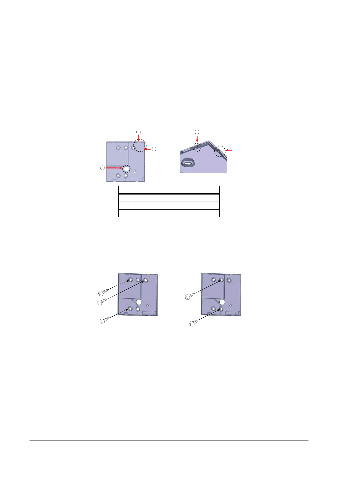
Electrical Connections
Liebert
®
SRC
™
User Manual 82
1. Once the proper location for the thermostat is determined, determine the cable-entry location from one
of three options:
• Back
• Top
• Right
2.If you use top or right -side entry, remove the cable-guide groove from the back plate with long-nose
pl
iers, Figure 6-15.
Figure 6-15 Cable-entry hole/guide grooves
3. Place the back plate in the installation location and secure it with sc rew, Figure 6-16.
• Do not bend the back plate
when tightening screws.
•If there is an electric box, fit the back plate to the box when installing.
• Do not leave a gap between the wall and back plate or the thermostat could move or shake.
Figure 6-16 Thermost
at back plate installation
No.Description
1Back entry (through wall)
2 Top entry
3 Right-side entry
2
2
1
3
3
MFL67502030 17. 7. 13. 오오 3:05 Page 92
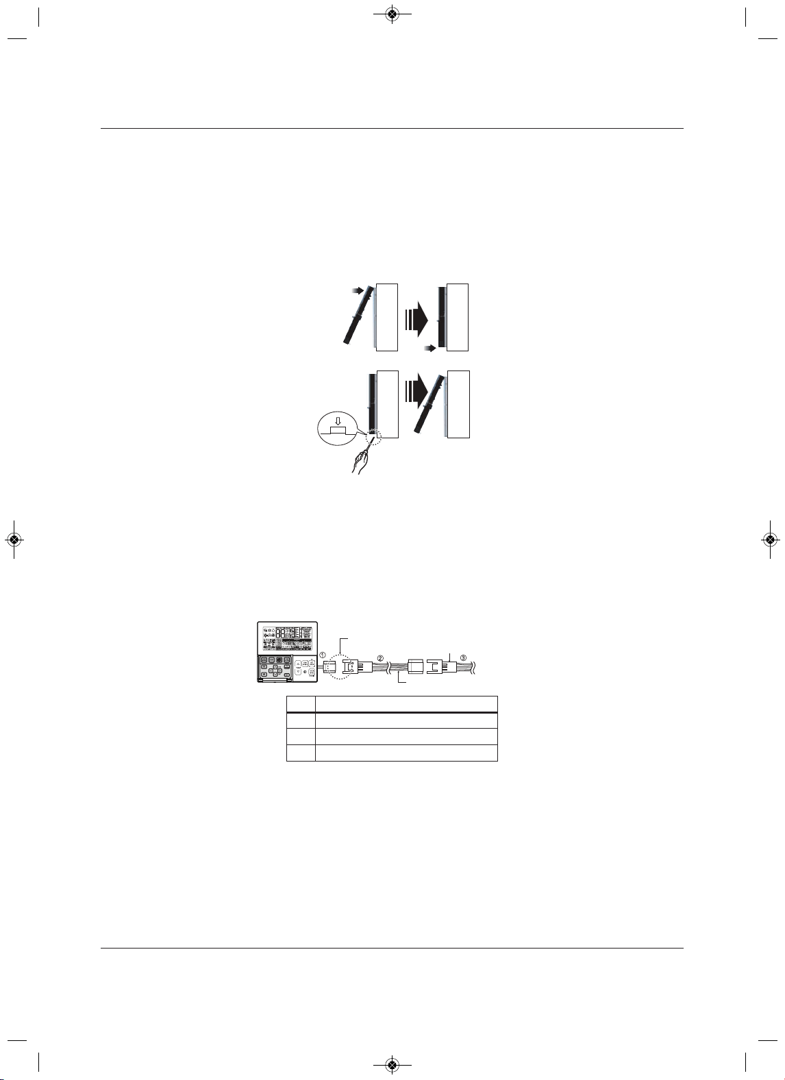
Electrical Connections
trebeiL38
®
SRC™ User Manua
l
4. Making sure that the cable does not interfere, place the upper part of the thermostat on the back plate
as shown in Figure 6-17, and press the lower part onto the back plate to connect it.
• Leave no gaps between the thermostat and the back plate.
• To remove the thermostat from the back plate, insert a screwdriver into one of the separating holes
on the bottom of the thermostat and twist. Repeat in the second hole, to release the thermostat
from the back plate.
Figure 6-17 Mounting thermostat onto back plate
5. Refer to Figure 6-18 to connect the indoor unit to the thermostat using the extension cable.
NOTICE
Risk of improper thermostat installation. Can cause unit malfunction.
If local electric and building code requires plenum(CMP) cable, use an enclosed, non-combustible
conduit (metal raceway) or FT-6 rated or above cable.
Figure 6-18 Extension cable from indoor unit to thermostat
6. To connect the extension cable directly to the thermostat
• Loosen the screw holding the cable in the thermostat terminal block.
• Use a cutting nipper to remove the housing from the extension cable and peel it as shown in
Figure 6-19.
No. Description
1AWG#24
2AWG#22
3AWG#22
Wall
Side
Wall
Side
Wall
Side
Wall
Side
<Connecting or der>
<Separating or der>
Please check if the connectors are connected properly.
C/BO X Cable (Plug type)
Extension cable(Housing type)
Indoor
Unit side
MFL67502030 17. 7. 13. 오오 3:05 Page 93
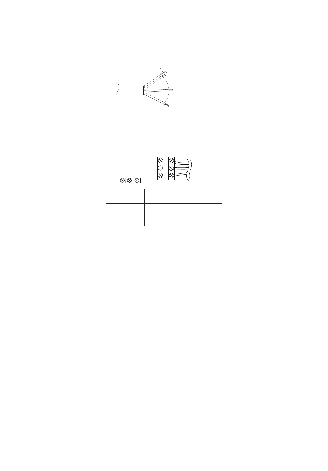
Electrical Connections
Liebert
®
SRC
™
48launaM resU
Figure 6-19 Thermostat cable prep
7. Connect the wires to the thermostat terminal block and the indoor-unit terminal block as shown in
Figure 6-20.
• Tighten securely and make sure wires are not touching each other.
Figure 6-20 Thermostat and Indoor unit terminal-block connections
Thermostat
terminal block
Indoor-unit
terminal block Function
YELLOW YL Signal
RED RD 12 V
BLACK BK GND
1.378 inch(35mm)
± 0.197 inch(5mm)
0.394 inch(10mm) ± 0.11 8 inch(3mm)
YELLOW RED BLACK
Signal 12V GND
Thermostat PCB
Indoor unit
side
MFL67502030 17. 7. 13. 오오 3:05 Page 94
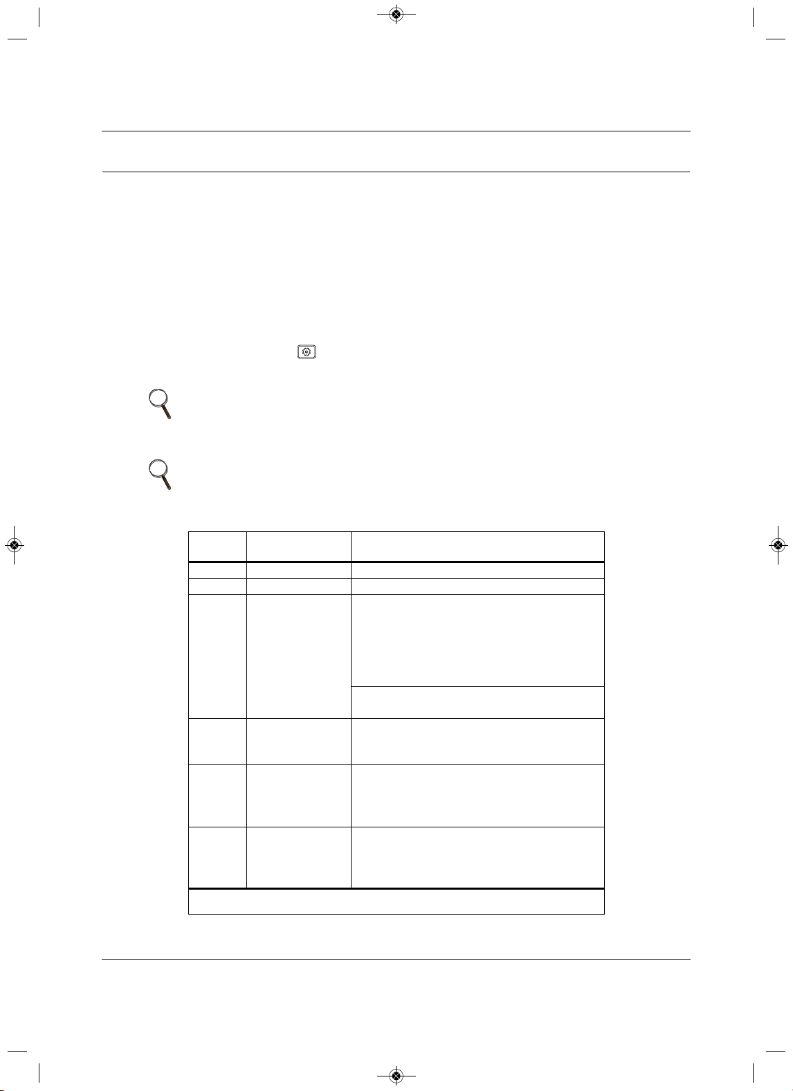
Installation Set-up and System Start-up
85 Liebert
®
SRC™ User Manual
7.0 Installation Set-up and System Start-up
NOTICE
Risk of improper thermostat installation. Can cause unit malfunction.
The Installer setting mode sets up the detailed function of the thermostat.
If the installation is not set correctly, it can cause problems for the product, user injury, or property
damage. Install
ation set-up must be performed by a certified technician. Non-certified personnel
attempting to install or make changes shall be responsible for any adverse effects or operation.
7.1 Accessing Installer Set-up Mode
1. On the thermostat, press for at least 3 seconds.
The function code displays.
2. Refer to the following procedures and Table 7-1 to make the correct settings for your installation.
NOTE
A press less than 3 seconds enters “user” settings mode.
NOTE
Some menu options and functions may not be displayed or the menu name
may be different depending on your system and model.
Table 7-1 General unit functions—Installer set-up codes
Function
Code Description Value
01 Test Run 01 = Set
02 Address Setting 00 ~ FF = Address
03 E.S.P Value
Step:
01 = Very Low
02 = Low
03 = Med
04 = High
05 = Very High
Value:
0 ~ 255
04 Thermistor
01 = Remo
02 = I
ndoor
03 = 2TH
05 Ceiling Height
01 = Low
02 = Med
03 = High
04 = Very High
06 Static Pressure
01 = V-H
02 = F-H
03 = V-L
04 = F-L
Some menu options and functions may not be displayed or the menu name may be different
depending on your system and model.
MFL67502030 17. 7. 13. 오오 3:05 Page 95
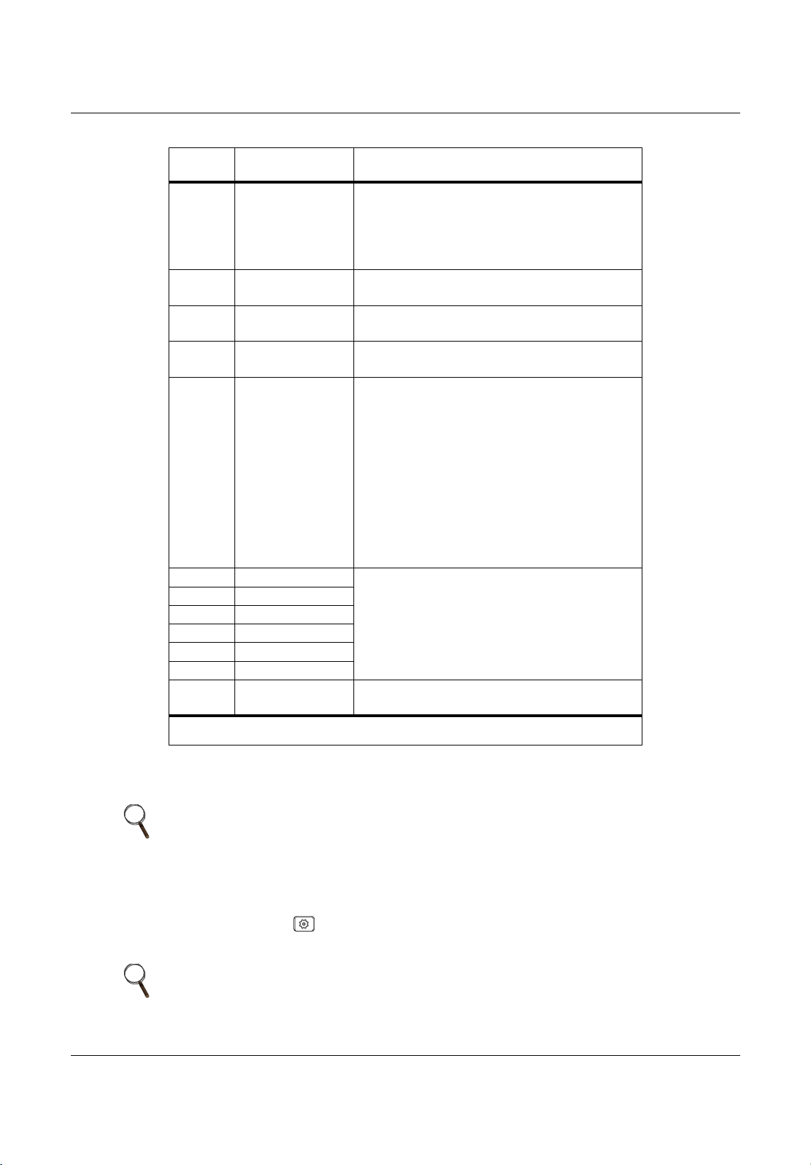
Installation Set-up and System Start-up
Liebert
®
SRC
™
User Manual 86
7.2 Running Test Mode
1. On the thermostat, press for at least 3 seconds.
The function code blinks in the lower-middle of the display.
07 M aster setting
00 = Slave
01 = Master
(only “Plus 1 series models)
00 = Group
01 = Single
08 Override setting
00 = Slave
01 = Master
09 Dry contact
00 = Auto-off
01 = Auto-on
12 Celsius/Fahrenheit
00 = Celsius
01 = Fahrenheit
18 Emergency heater
Select mode:
00 = not used
01 = use
Low-ambient heating operation:
0 = not used
1 = compressor off 0°F (–18°C)/ on 5°F (–15°C)
2 = compressor off 5°F (–15°C)/ on 10°F (–12°C)
3 = compressor off 10°F (–12°C)/ on
15°F (–9°C)
Fan speed:
0 = fan off
1 = fan on
20Plasma
00 = not installed
01 = installed
21 Electric heater
22 Humidifier
23 Elevation grill
24 Ventilation kit
25 Auxiliary heater
31
Settings temperature
range
00 = 60~86°F / 16~30°
C
01 = 40~99°F / 4~37.5°C
NOTE
Before running test mode, make sure of the following:
• Leak testing is complete and there are no leaks.
• Air purge/evacuation is complete and successful.
• All tubing, piping, and wiring are properly connected.
NOTE
A press less than 3 seconds enters “user” settings mode.
Table 7-1 General unit functions—Installer set-up codes (continued)
Function
Code Description Value
Some menu options and functions may not be displayed or the menu name may be different
depending on your system and model.
MFL67502030 17. 7. 13. 오오 3:05 Page 96
Installation Set-up and System Start-up
87 Liebert
®
SRC™ User Manual
2. Press .
The test run starts.
• During the test run, pressing any of the following buttons will exit the test: Oper Mode, Temp
up/down, Fan Speed, Wind Direction, or Start/Stop.
7.3 Setting the Address of Central Contro l
Refer to Table 7-1 for the specific function-setting values.
1. On the thermostat, press for at least 3 seconds.
The function code blinks in the lower-middle of the display.
2. P ress repeated ly to select the function code.
3. Press
, to select the Group No., then use to select the setting.
4. Press , to select the Indoor No., then use to select the setting.
5. Press .
The setting is saved.
6. Press to exit installer setting mode.
7.4Setting E.S.P.
This function determines the wind-strength for each wind level.
Refer to Table 7-1 for the specific function-setting values.
1. On the thermostat, press for at least 3 seconds.
The function code blinks in the lower-middle of the display.
2. P ress
repeatedly to select the function code.
3. Press to select the Step (wind level).
4. Press to select the Value (wind strength), then use to select the setting.
NOTE
A press less than 3 seconds enters “user” settings mode.
NOTE
If there is no button input for 25 seconds, set-up mode is automatically exited.
If you exit without pressing , your settings are not saved.
NOTE
If E.S.P is set incorrectly, the unit may malfunction.
ESP may not work on products that do not have “weak” or power fan-speed
settings.
NOTE
A press less than 3 seconds enters “user” settings mode.
MFL67502030 17. 7. 13. 오오 3:05 Page 97
Installation Set-up and System Start-up
Liebert
®
SRC
™
User Manual 88
5. Press then to select the next Step.
6. Press to select the Value, then use to select the setting.
7. Repeat Step s5 to 6 until the strength is set for each wind level.
8. Press .
The setting is saved.
• Press to
exit installer setting mode.
7.5 Setting the Thermistor
Refer to Table 7-1 for the specific function-setting values.
1. On the thermostat, press for at least 3 seconds.
The function code blinks in the lower-middle of the display.
2. P ress repeated ly to select the function code.
3. Press ,
to select Value, then use to select the setting. Refer to Table 7-2 for descriptions of
the thermistor settings.
4. Press .
The setting is saved.
5. Press to exit installer setting mode.
NOTE
If there is no button input for 25 seconds, set-up mode is automatically exited.
If you exit without pressing , your settings are not saved.
NOTE
A press less than 3 seconds enters “user” settings mode.
Table 7-2 Thermistor setting options
Value Function
01 Thermostat Operates based on temperature sensor in thermostat.
02 Indoor Unit Operates based on temperature sensor in indoor unit.
032TH
Cooling
Operates based on higher temperature comparing the
reading from thermostat temp. sensor and indoor-unit
temp sensor.
Heating
Operates based on lower temperature comparing
the
reading from thermostat temp. sensor and indoor-unit
temp sensor.
The 2TH functions differently depending on product model.
If the indoor temperature is below 10°F, the value for the temperature sensor of the thermostat is
displayed regardless of the thermistor setting.
NOTE
If there is no button input for 25 seconds, set-up mode is automatically exited.
If you exit without pressing , your settings are not saved.
MFL67502030 17. 7. 13. 오오 3:05 Page 98
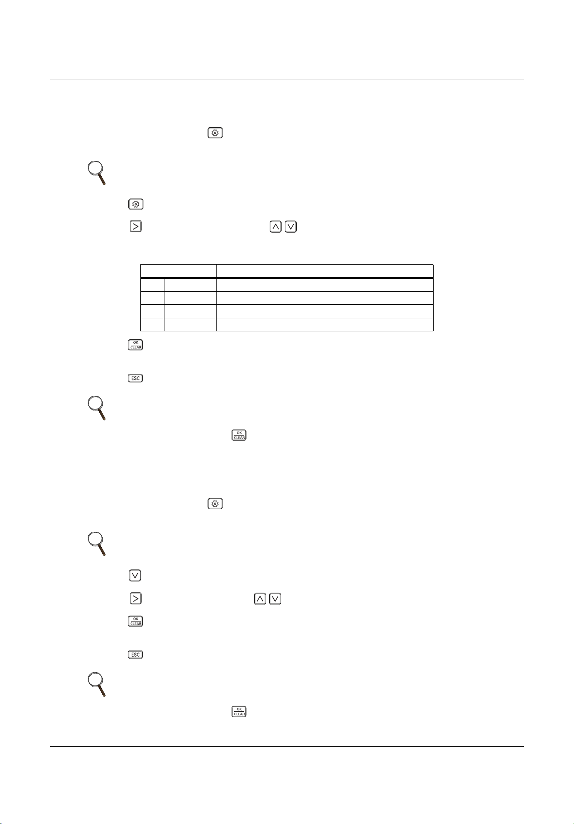
Installation Set-up and System Start-up
89 Liebert
®
SRC™ User Manual
7.6 Setting the Ceiling Height
Refer to Table 7-1 for the specific function-setting values.
1. On the thermostat, press for at least 3 seconds.
The function code blinks in the lower-middle of the display.
2. P ress repeated ly to select the function code.
3. P ress ,
to select the Value, then use to select the setting. Refer to Table 7-3 for
descriptions of the ceiling-height settings.
4. Press .
The setting is saved.
5. Press to exit installer setting mode.
7.7 Setting Fahrenheit/Celsius
Refer to Table 7-1 for the specific function-setting values.
1. On the thermostat, press for at least 3 seconds.
The function code blinks in the lower-middle of the display.
2. P ress to select the function code.
3. P ress , to
select Value, then use to select the setting.
4. Press .
The setting is saved.
5. Press to exit installer setting mode.
NOTE
A press less than 3 seconds enters “user” settings mode.
Table 7-3 Ceiling-height setting options
Value Func tion
01 Low Decrease indoor air-flow rate 1 step from standard level.
02 Medium Set indoor air-flow rate as standard level.
03 High Increase indoor air-flow rate 1 step from standard level.
04 Very high Increase indoor air-flow rate
2 steps from standard level.
NOTE
If there is no button input for 25 seconds, set-up mode is automatically exited.
If you exit without pressing , your settings are not saved.
NOTE
A press less than 3 seconds enters “user” settings mode.
NOTE
If there is no button input for 25 seconds, set-up mode is automatically exited.
If you exit without pressing , your settings are not saved.
MFL67502030 17. 7. 13. 오오 3:05 Page 99
Installation Set-up and System Start-up
Liebert
®
SRC
™
User Manual 90
7.8 Setting Optional Functions
Used when options are added or removed.
Refer to Table 7-1 for the specific function-setting values.
1. On the thermostat, press for at least 3 seconds.
The function code blinks in the lower-middle of the display.
2. P ress repeated ly to se
lect the function code.
3. Press , to select the condition, then use to select the setting.
4. Press .
The setting is saved.
5. Press to exit installer setting mode.
7.9 Setting Temperature Range
Refer to Table 7-1 for the specific function-setting values.
1. On the thermostat, press for at least 3 seconds.
The function code blinks in the lower-middle of the display.
2. P ress repeated ly to select the function code.
3. Press
, to select the Value, then use to select the setting.
4. Press .
The setting is saved.
5. Press to exit installer setting mode.
NOTE
A press less than 3 seconds enters “user” settings mode.
NOTE
If there is no button input for 25 seconds, set-up mode is automatically exited.
If you exit without pressing , your settings are not saved.
NOTE
A press less than 3 seconds enters “user” settings mode.
NOTE
If there is no button input for 25 seconds, set-up mode is automatically exited.
If you exit without pressing , your settings are not saved.
MFL67502030 17. 7. 13. 오오 3:05 Page 100
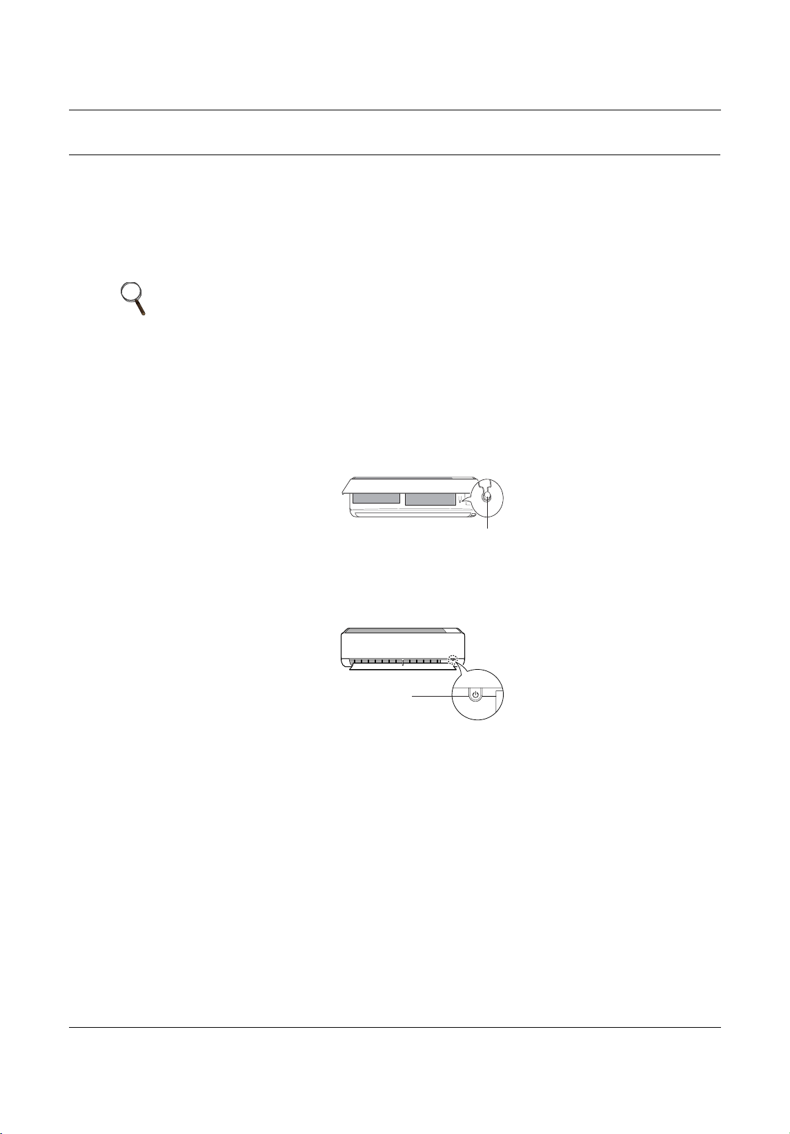
Operation
91 Liebert
®
SRC™ User Manual
8.0 Operation
8.1 Operating the Unit
Use the ON/OFF button on the indoor unit to operate the system.
1. D epending on the type of unit, Type 1 or Type 2 (Figure 8-1), open the front cover.
2. Press the ON/OFF button.
Figure 8-1
On/Off button lo cation
NOTE
• If the horizontal vane opens rapidly, the stepping motor may be broken.
• The fan speed is set too high. Depending on the model, fan speed may be
changed.
• You cannot change temperature using this ON/OFF button.
• For cooling-only models, the temperature is set to 71.6°F (22°C).
• For cooling-and-heating models, the temperature is set from 71.6°F (22°C)
to 75.2°F (24°C).
Type1
ON/OFF
Type2
ON/OFF
MFL67502030 17. 7. 13. 오오 3:05 Page 101

Operation
Liebert
®
SRC
™
User Manual 92
8.2 Automatic Unit Restart
When the unit is turned-on after a power failure, this function restores the previous settings.
Disabling Auto Restart
1. Open the front cover of the indoor unit.
2. P ress and hold the ON/OFF button for 6 seconds.
The unit beeps twice and the lamp blinks 4 times.
• To re-enable Auto Restart, press and hold the ON/OFF button for 6 seconds
.
The unit beeps twice and the lamp blinks 4 times.
8.3 Enabling Cooling-only Mode
Cooling-only mode is used when performing the Pump Down procedure. Cooling-only mode is set in
“Installer” mode.
1. Completely shut-down system power.
2. At the thermostat, access Installer mode by pressing for at least 3 seconds.
The
function code displays.
3. P ress repeated ly to select the function code 45, then power-on the unit.
The unit beeps to acknowledge that the code is received.
4. Turn-off power for at least 30 seconds.
5. Turn-on power to the system.
Cool
ing-only mode is enabled.
NOTE
Auto-restart may be changed depending on the type of model.
NOTE
Pressing and holding the ON/OFF button 3 to 5 seconds, instead of 6
seconds, initiates test operation. In test operation, the unit blows strong, cool
air fro 18 minutes then returns to factory-default settings.
NOTE
• Automatic operation is suspended when cooling-only mode is initiated in
Installer mode.
• When cooling-only mode is disabled, the unit returns to normal operation.
• Installer mode cannot be initiated if the unit is running. The system must be
powered-off completely.
• All Installer-mode function codes must be entered while the system is
powered-off (complete system shutdown).
• WLAN module’s communication time will lag by about 1 minute after the
unit is powered back on and normal operation resumes.
• Entire lock or Mode lock cannot be set if you set heating or automatic
operation through the central controller.
NOTE
A press less than 3 seconds enters “user” settings mode.
MFL67502030 17. 7. 13. 오오 3:05 Page 102
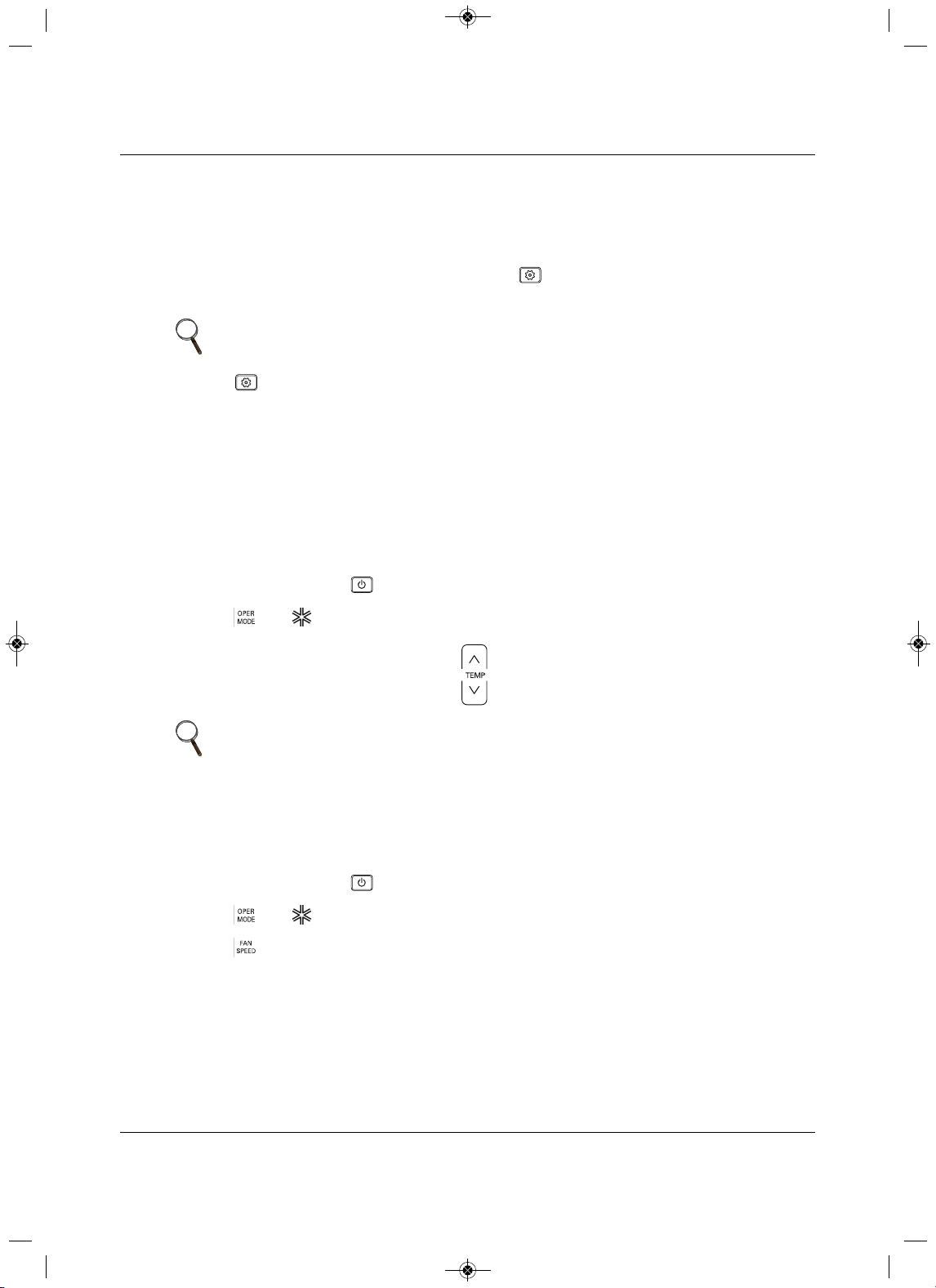
Operation
93 Liebert
®
SRC™ User Manual
8.4 Disabling Cooling-only Mode
Cooling-only mode is used when performing the Pump Down procedure. Once pump-down is complete,
disable cooling-only and return to normal operation using the following procedure.
1. Completely shut-down system power.
2. At the thermostat, access Install
er mode by pressing for at least 3 seconds.
The function code displays.
3. P ress repeated ly to select the function code 46, then power-on the unit.
The unit beeps to acknowledge that the code is received.
4. Turn-off power for at least 30 seconds
.
5. Turn-on power to the system.
Cooling-only mode is disabled.
8.5 Standard Operation
8.5.1 Selecting Cooling Mode
1. On the thermostat, press to power-on the indoor unit.
2. P ress until displays in the operation-mode section.
3. A djust the temperature setting by pressing .
8.5.2 Selecting Power Cooling
Power cooling lets you cool or warm the indoor air quickly and is available with cooling, heating, and
dehumidification modes.
1. On the thermostat, press to power-on the indoor unit.
2. P ress until displays in the operation-mode section.
3. P
ress until Po displays under the Cooling-temperature setpoint in the temperature section.
NOTE
A press less than 3 seconds enters “user” settings mode.
NOTE
The temperature range varies depending on Installer set-up.
• Factory default is 64~86°F (18~30°C).
MFL67502030 17. 7. 13. 오오 3:05 Page 103
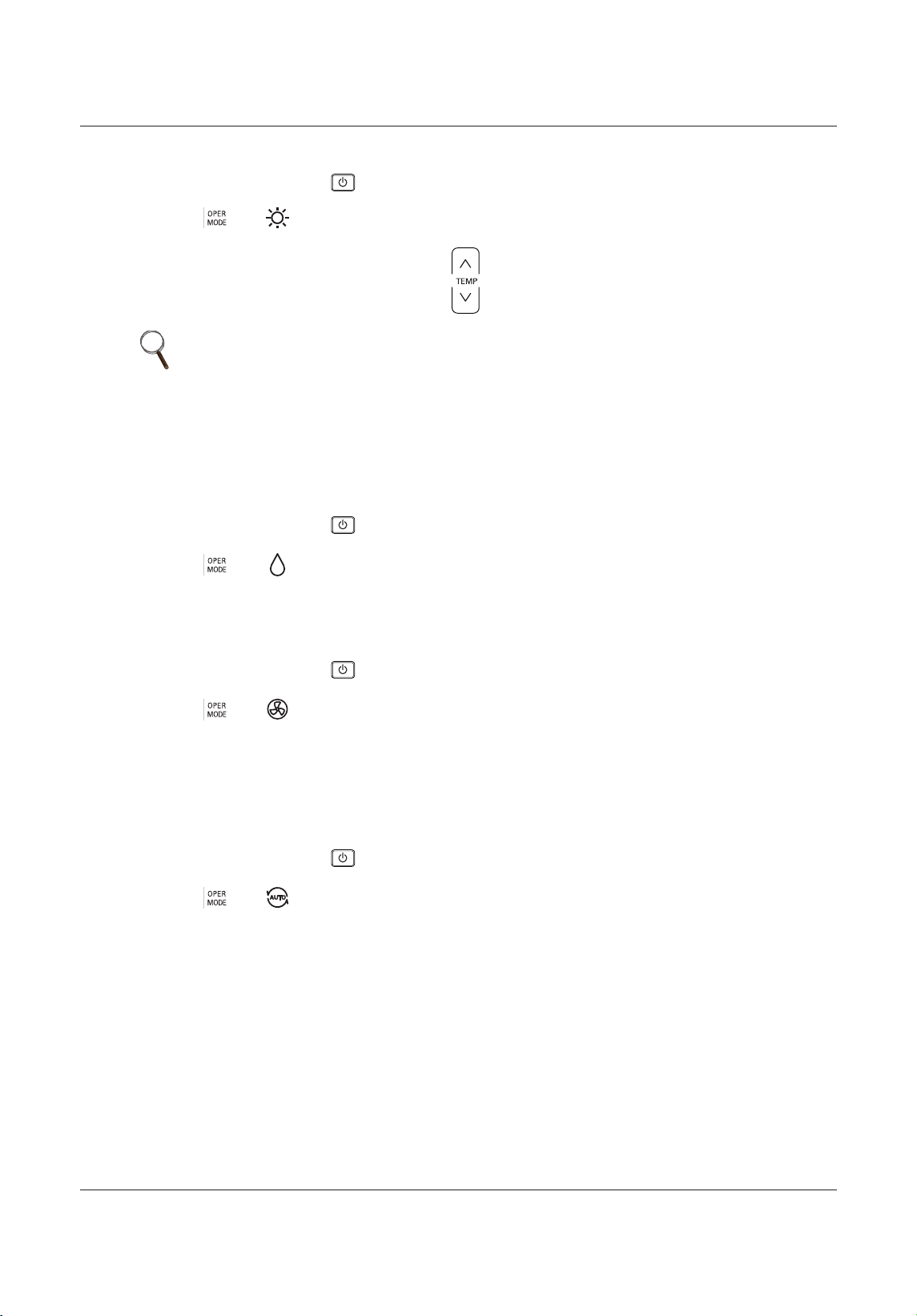
Operation
Liebert
®
SRC
™
User Manual 94
8.5.3 Selecting Heating Mode
1. On the thermostat, press to power-on the indoor unit.
2. Press until displays in the operation-mode section.
3. Adjust the temperature setting by pressing .
8.5.4 Selecting Dehumidification Mode
Dehumidification removes moisture from a highly-humid environment, especially during the rainy season,
to prevent mold from setting-in. Dehumidification mode adjusts room temperature and fan speed
automatically to maintain the optimal humidity level.
1. On the thermostat, press to power-on the indoor unit.
2. Press until displays in the operation-mode section.
8.5.5 Selecting Fan Mode
Fan mode circulates indoor air without changing the room temperature.
1. On the thermostat, press to power-on the indoor unit.
2. Press until displays in the operation-mode section.
8.5.6 Selecting Auto Mode
Auto mode changes modes automatically to maintain the temperature setpoint within ±3.6°F (±2°C).
When operating in auto mode, the Auto icon and cool, heat, etc. icon display simultaneously in the
Operating Mode section to indicate the current mode.
1. On the thermostat, press to power-on the indoor unit.
2. Press until displays in the operation-mode section.
NOTE
The temperature range varies depending on Installer set-up.
• Factory default is 60~86°F (16~30°C).
MFL67502030 17. 7. 13. 오오 3:05 Page 104
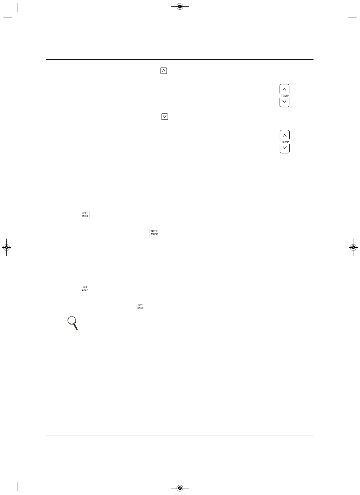
Operation
95 Liebert
®
SRC™ User Manual
3. Set the cooling setpoint by pressing ,
then adjust the temperature displayed
under Cool-temperature setpoint in the Temperature section of the display by pressing .
4. Set the cooling setpoint by pressing ,
then adjust the temperature displayed
under Heat-temperature setpoint in the
Temperature section of the display by pressing .
8.5.7 Selecting Timed Override
Timed override temporarily overrides the current schedule (occupied/unoccupied).
• Reverts to last occupied schedule in unoccupied override.
• Reverts to last unoccupied schedule in occupied override.
See 8.6.5, Setting Override Time, page 98, to set the duration of the override.
Press for 3 seconds.
Timed
override is enabled.
• To cancel timed override, press for 3 seconds.
Operation reverts to last weekly schedule.
8.5.8 Selecting Set Back
Set Back reverts to the last unoccupied schedule until set-back operation is canceled. If there is no
unoccupied schedule, it returns to the default set-back setting. See 8.6.6, Setting Set-back Temperature,
page 98, to set the set
-back setting.
Press .
Set back is enabled.
• To cancel set back, press .
NOTE
• You cannot changes settings in set-back mode. HL and the lock is
displayed.
• Set back is canceled if a command from another controller is received.
COO
L
HEAT
MFL67502030 17. 7. 13. 오오 3:05 Page 105
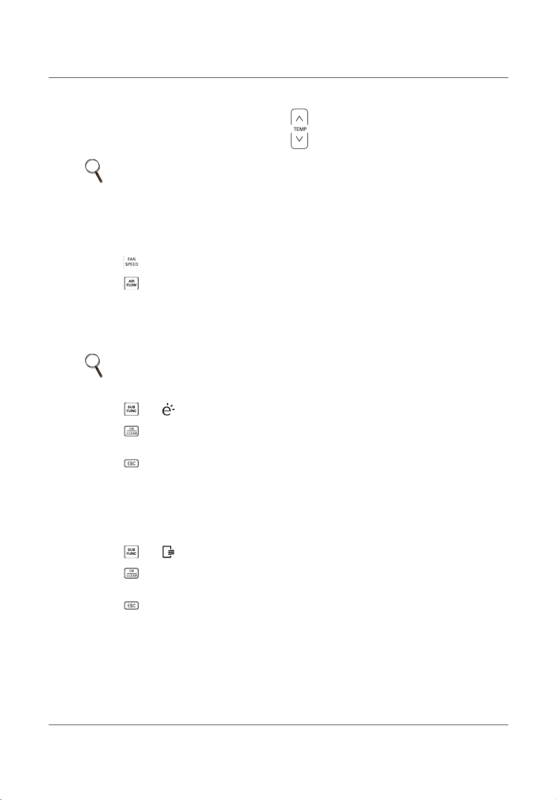
Operation
Liebert
®
SRC
™
User Manual 96
8.5.9 Setting the Temperature
You can adjust the temperature simply by pressing .
8.5.10 Adjusting Air Flow
1. Press to cycle through the fan-speed options (displayed in Fan Speed section).
2. Press to cycle through the wind-direction options (displayed in Air-flow/Louvers section).
8.5.11 Selecting Energy-saving Cooling
Energy-saving cooling operation improves comfort and power-saving capacity by automatically adjusting
temperature during cooling mode.
1. P ress until is displayed in the sub-function section of the display.
2. Press .
The setting is saved.
3. P ress to exit the sub-function set
-up.
8.5.12 Selecting Automatic Drying
Automatic drying dries the inside of the indoor unit when it is turned-off by operating the fan to remove
moisture and prevent mold.
1. P ress until is displayed in the sub-function section of the display.
2. Press .
The setting is saved.
3.
Press to exit the sub-function set-up.
NOTE
In Auto mode, both setpoints adjust automatically when you set the
temperature in this way.
To adjust the cooling or heating setpoint individually, press the appropriate
button before adjusting the temperature.
NOTE
Energy-save mode can only be set up in Cooling mode and does not operate
with Auto Mode.
MFL67502030 17. 7. 13. 오오 3:05 Page 106
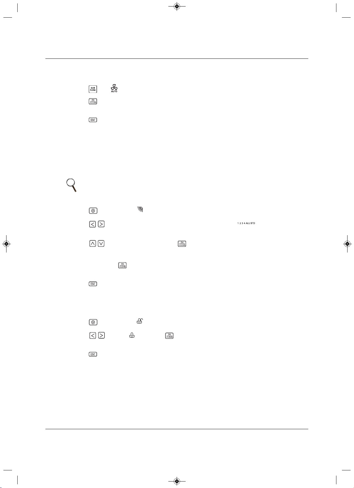
Operation
97 Liebert
®
SRC™ User Manual
8.5.13 Selecting Fan Auto
Operates the fan when the outdoor unit is running.
1. P ress until is displayed in the sub-function section of the display.
2. Press .
The setting is saved.
3. P ress to exit the sub-function set-up.
8.6 Function Settings
8.6.1 Setting Louver Angle Control
Adjusts the angle of airflow.
1. P ress repeatedly until flashes in the Function Settings section of the display.
2. Press to select the vane number, or All to set all vanes at once (STD sets all louvers
to factory-default).
3
. Press to select the angle, then press .
4. Repeat Steps2 and 3 for each louver if needed.
5. When done, P ress .
The settings are saved.
6. P ress to exit the function set-up.
8.6.2 Locking the Display
Locks the display to prevent un-authorized use.
1. Press repeatedly until f lashes in the Function Settings section of the display.
2. P ress to select , then press .
The display is locked.
3. P ress to exit the function set-up.
NOTE
While louver/vane angle is adjusted, commands from the central controller
are delayed for 1 minute.
MFL67502030 17. 7. 13. 오오 3:05 Page 107
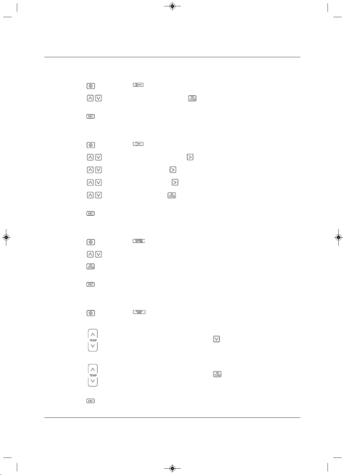
Operation
Liebert
®
SRC
™
User Manual 98
8.6.3 Setting the Minimum Difference
between the Cooling and Heating Setpoints
1. Press repeatedly until flashes in the Function Settings section of the display.
2. P ress to select the temperature, then press .
The minimum difference is set.
3. P ress to exit the function set-up.
8.6.4 Setting Current Time
1. Press repeatedly until flashes in the Function Settings section of the display.
2. Press to select the current day, then press to move to AM/PM setting.
3. Press to select AM/PM, then press to move to hour setting.
4. P
ress to select the hour, then press to move to minute setting.
5. Press to select minute, then press .
Current time is set.
6. P ress to exit the function set-up.
8.6.5 Setting Override Time
1. Press repeatedly until flashes in the Function Settings section of the display.
2. P ress to select the duration of the override interval from 30 to 240 minutes.
3. Press .
Override interval is set.
4. Press to exit the function set-up.
8.6.6 Setting Set-back Temperature
1. Press repeatedly until flashes in the Function Settings section of the display, and the Cool
setpoint temperature flashes in the Temperature section.
2. Press to select the set-back cooling setpoint, then press , to move to the Heat setpoint
temperature.
3. Press to select the set-back heating setpoint, then press .
The set-back setpoint temperatures are set.
4. Press to exit the function set-up.
MFL67502030 17. 7. 13. 오오 3:05 Page 108
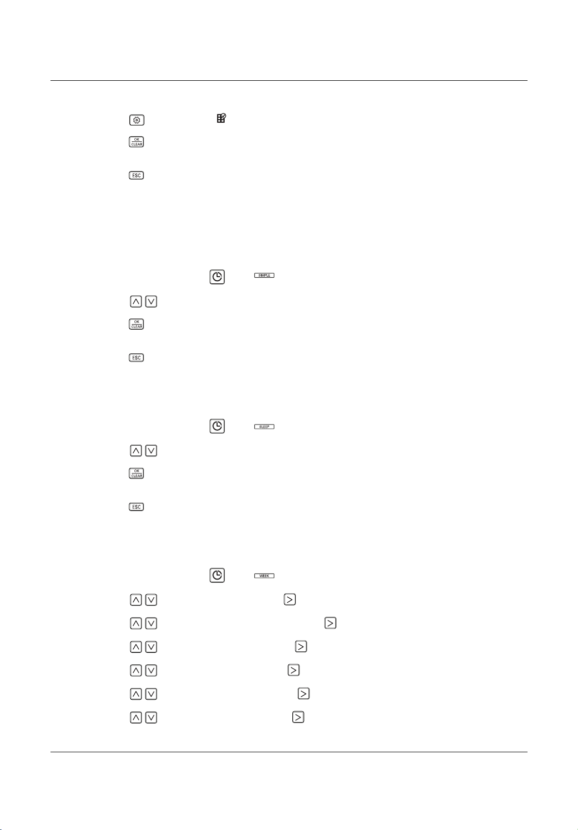
Operation
99 Liebert
®
SRC™ User Manual
8.6.7 Clearing the “Clean Filter” Alarm
1. Press repeatedly until flashes in the Function Settings section of the display.
2. Press .
The display is cleared.
3. P ress to exit the function set-up.
8.7 Schedule Set-up
8.7.1 Simple Schedule
A simple schedule automatically runs for a specified time then stops.
1. On the thermostat, press until displays in the Schedule section.
2. P ress to select the sleep time from 1 to 3 hours.
3. Press .
The schedule is set.
4.
Press to exit the function set-up.
8.7.2 Sleep Schedule
A sleep schedule shuts-off the unit for a specified time.
1. On the thermostat, press until displays in the Schedule section.
2. P ress to select the duration of the schedule from 1 to 7 hours.
3. Press .
The schedule is
set.
4. Press to exit the function set-up.
8.7.3 Weekly Schedule
A weekly schedule sets up daily-operation schedules for the week.
1. On the thermostat, press until displays in the Schedule section.
2. P ress to select the day, then press to move to the timer section.
3. P ress to select the
timer number, then press to move to AM/PM section.
4. Press to select AM or PM, then press to move to the hour section.
5. Press to select the hour, then press to move to the minute section.
6. P ress to select
the minute, then press to move to the ON/OFF section.
7. P ress to select On or Off, then press to move to the OCCUPIED/UNOCCUPIED section.
MFL67502030 17. 7. 13. 오오 3:05 Page 109
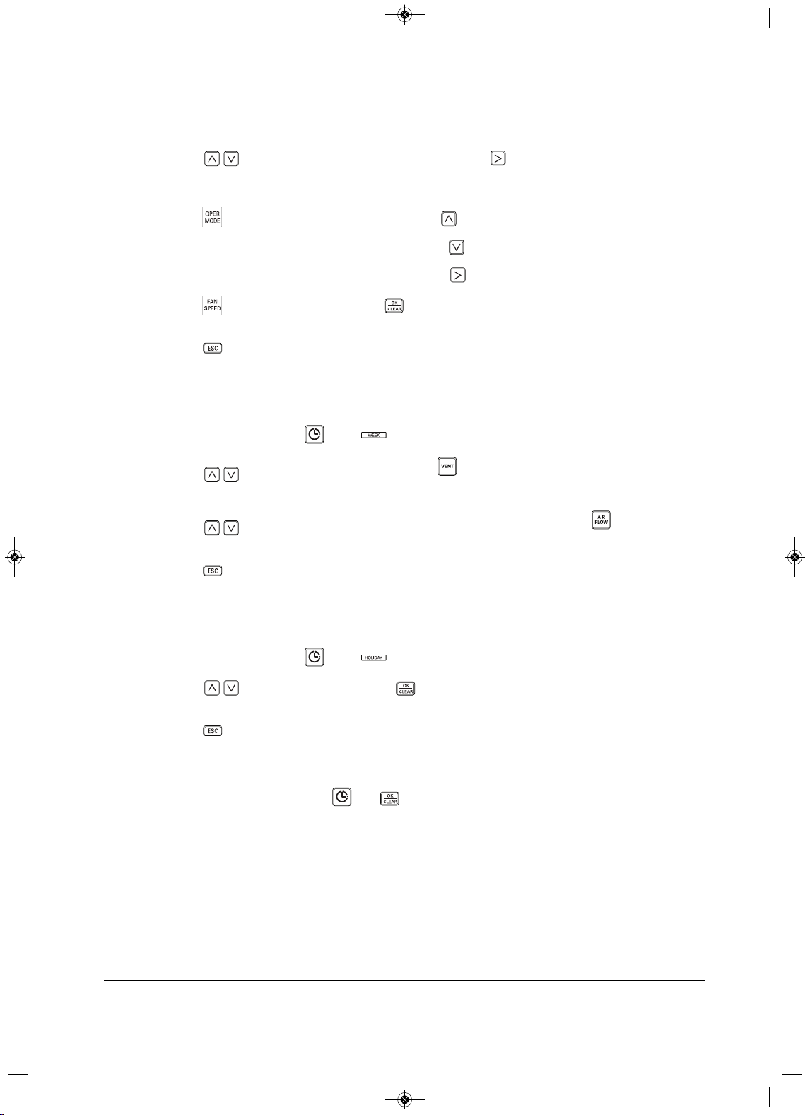
Operation
Liebert
®
SRC
™
User Manual 100
8. P ress to select Occupied or Unoccupied, then press to move to the Operation Mode
section.
The operating-mode icon blinks.
9. P ress to select the operating mode, then press .
10. Set the cooling setpoint for the schedule, then press .
11. S
et the heating setpoint for the schedule, then press to move to the Fan Speed section.
12. Press to select the fan speed, press .
The schedule is set.
13. Press to exit the function set-up.
8.7.4 Copy/Paste a Schedule
You can copy a weekly schedule to another day.
1. On the thermostat, press until displays in the Schedule section.
2. Press to select the day to copy, then pres s for 3 seconds.
The COPY icon f lashes in the Schedul
e section.
3. Press to select day to which you want to paste the schedule, then press for 3 seconds.
The PASTE icon flashes in the Schedule section, and the schedule is pasted.
4. Press to exit the function set-up.
8.7.5 Schedule a Holiday
Schedules stop on the day reserved.
1. On the thermostat, press until displays in the Schedule section.
2. Press to select the day, then press .
The holiday is set.
3. P ress to exit the function set-up.
8.7.6 Delete all Schedules
On the thermostat, press and hold and simultaneously for 3 seconds.
COO
L
HEAT
COPY
PASTE
MFL67502030 17. 7. 13. 오오 3:05 Page 110
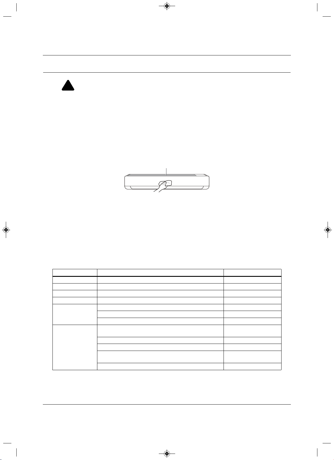
Maintenance
101 Liebert
®
SRC™ User Manual
9.0 Maintenance
If the unit will not be used for an extended period of time, dry the unit to maintain it in the best condition.
Clean the unit regularly to maintain optimal performance and to prevent possible breakdown.
• Dry the unit in Fan mode for 3 to
4 hours and disconnect the power. There may be internal damage if
moisture is left in unit’s components.
• Before using the unit again, dry the unit in Fan mode for 3 to 4 hours to remove odor generated by
moisture.
Figure 9-1 Cleaning the
outside of the in door unit
NOTICE
Risk of improper cleaning. Can cause cabinet finish damage.
•Never use water that is higher than 104° (40°C) when you clean the filters. It may cause
deformation or discoloration.
•Never use volatile substances when you clean the filters
. These may damage the surface of the
unit.
• Do not wash the 3M filter (optional) with water because it can be damaged by water.
• Do not wash the Triple filter (optional) with water because it can be damaged by water.
!
WARNING
Arc flash and electric shock hazard. Can cause serious injury or death. Open all local and remote
electric power disconnect switches, verify with a voltmeter that power is off and wear personal
protective equipment per NFPA 70E before working within the
electric control enclosure.
Table 9-1 Cleaning Schedule
Component Description Interva l
Air filter Clean with a vacuum or hand wash. 2 weeks
Triple filter Clean with a vacuum or brush.Every 3 months
3M filter Clean with a vacuum or brush.Every 6 months
I
onizer (optional) Use a dry cotton bud to remove any dust.Every 6 months
Indoor unit
Clean the surface using a soft, dry cloth. Regularly
Have a professional clean the condensate drain pan. Once a year
Have a professional clean the condensate drain pipe.E
very 4 months
Outdoor unit
Have a professional clean the heat-exchanger coils and the
panel vents. (Consult a technician.)
Once a year
Have a professional clean the fan. Once a year
Have a professional clean the condensate drain pan Once a year
Have a professional verify that the
fan assembly is firmly
tightened.
Once a year
Clean the electric components with air. Once a year
Air Filter
MFL67502030 17. 7. 13. 오오 3:05 Page 111
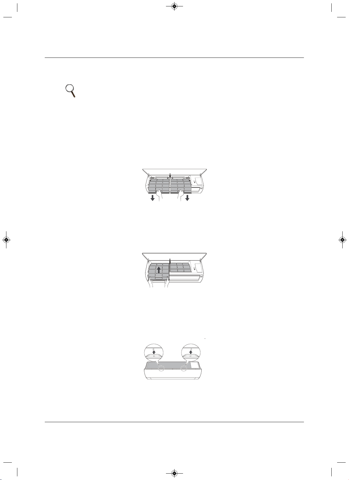
Maintenance
Liebert
®
SRC
™
User Manual 102
9.1 Cleaning the Air Filter
Clean the air filter once every 2 weeks or more if necessary.
9.1.1 Cleaning the Air Filter on Type 1 Units
1. Turn-off power and unplug the power cord.
2. Open the front cover by lifting both sides of the cover slightly.
3.Hold the knobs on the air filters, pull them down slightly and remove them from the unit, Figure 9-2.
Figu
re 9-2 Removing the air filter from Type 1 unit
4. Clean the filters with a vacuum cleaner or lukewarm water with a neutral detergent.
5. Dry the filters in the shade.
6.Insert the hooks
of the air filters into the front cover, Figure 9-3, and make sure the filters are inside
the cover for correct assembly.
Figure 9-3 Inserting cleaned air filter in Type 1 unit
9.1.2Cleaning the Air Filter on Type 2 Units
1. Turn-off power and unplug the power cord.
2.Hold the knobs on the air filters, lift up slightly, Figure 9-4.
Figure 9-4 Knobs on air filter of Type 2 unit
NOTE
• Bending the air filter can break it.
• If the air filter is not assembled correctly, dust and other substances can
enter the indoor unit.
MFL67502030 17. 7. 13. 오오 3:05 Page 112
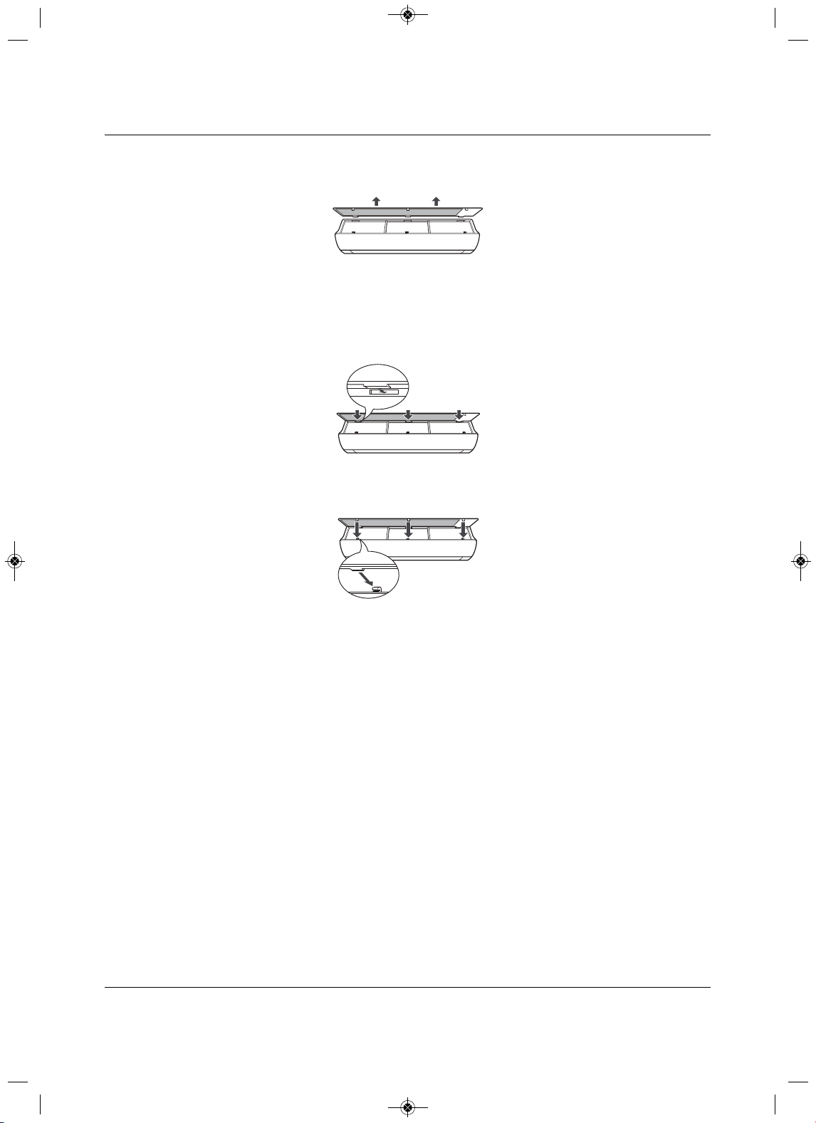
Maintenance
103 Liebert
®
SRC™ User Manual
3. Remove them from the unit, Figure 9-5 .
Figure 9-5 Removing the air filter from Type 2 unit
4. Clean the filters with a vacuum cleaner or lukewarm water with a neutral detergent.
5
. Dry the filters in the shade.
6.Insert the hooks of the air filters into the front cover, Figure 9-6.
Figure 9-6 Inserting cleaned air filter on the hooks of the
Type 2 unit
7. P ress down onto hooks, Figure 9-7, and make sure the filters are installed correctly.
Figure 9-7 Pus h down on the hooks of the Type 2 uni t
MFL67502030 17. 7. 13. 오오 3:05 Page 113
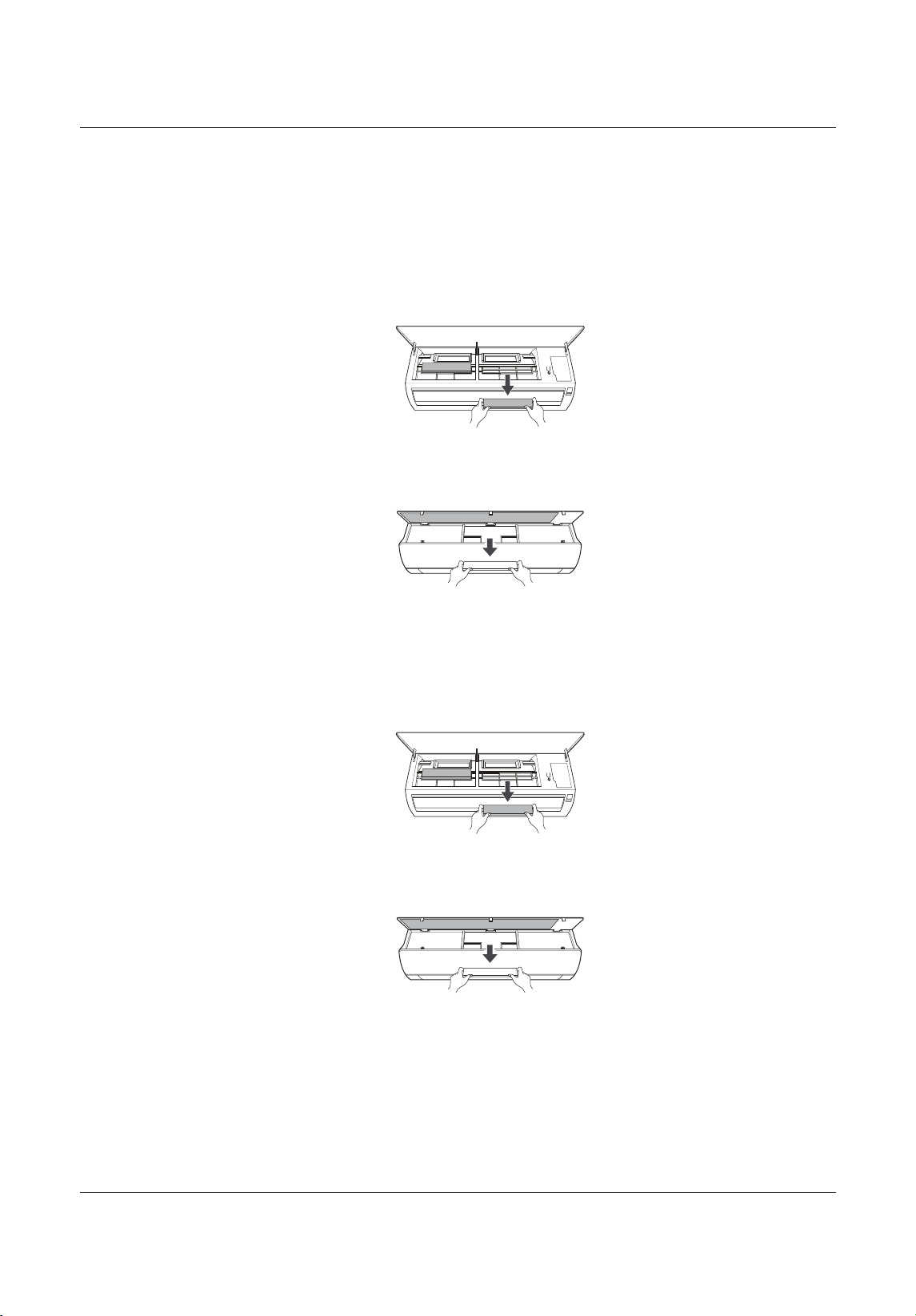
Maintenance
Liebert
®
SRC
™
User Manual 104
9.2 Cleaning the Optional 3M or Triple Filter
1. Turn off power and unplug the power cord.
2. Remove the air filters from the unit.
3. Remove the 3M and/or Triple filters from the unit, Figure 9-8.
Figure 9-8 Removing 3M/Triple filters from
indoor unit
4. Clean the filters with a vacuum cleaner.
5.Insert the 3M and/or Triple filters in the unit, Figure 9-9.
Figure 9-9 Replacing 3M/Triple filters in the indoor
unit
6. Replace the air filters.
7. C heck the sides of the front cover to make sure the air filters are installed correctly.
Type1
Type2
Type1
Type2
MFL67502030 17. 7. 13. 오오 3:05 Page 114
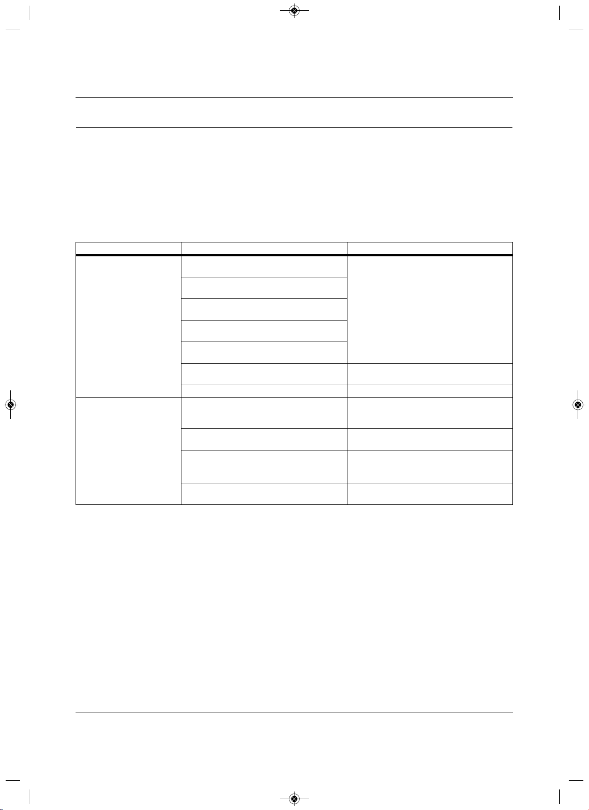
Troubleshooting
105 Liebert
®
SRC™ User Manual
10.0 Troubleshooting
10.1Self-diagnosis at the Indoor Unit
The Liebert SRC has a built-in self-diagnosis function. If an error occurs, the lamp of the indoor unit blinks
in 2-second intervals. If this occurs, contact your dealer or service center.
10.2 Before Calling for Service
Please check the following before contacting service. If the problem persists after corrective action, contact
your local service center.
Prob lem Possible Causes Corrective Action
The unit does not work
normally.
Burning smell and strange sounds are coming
from the unit.
• Turn-off the unit, unplug the power cable or
disconnect the power supply, and contact
service
.
Water leaks from the indoor unit even when
humidity level is low.
The power cable is damaged or it is generating
excessive heat.
A switch, circuit breaker (safety, ground), or a
fuse is not operating properly.
The unit generates and error code from
self
diagnosis.
Incorrect cabling.
• Check the communication cable
connections.
Incorrect scheduling setup. • Check the programmed Schedule settings.
The unit does not work.
The unit is unplugged.
• Check to see if the power cord is plugged
into the outlet
or if the power isolators are
switched on.
A fuse exploded or the power supply is
blocked.
•Replace the fuse or check to see if the circuit
breaker is tripped.
Voltage is too high or too low.
• Turn of the unit when
a power failure occurs.
• When the power is restored, wait 3 minutes
before turning-on the unit.
The unit was turned-off automatically at a
scheduled time.
• Turn the unit on.
MFL67502030 17. 7. 13. 오오 3:05 Page 115
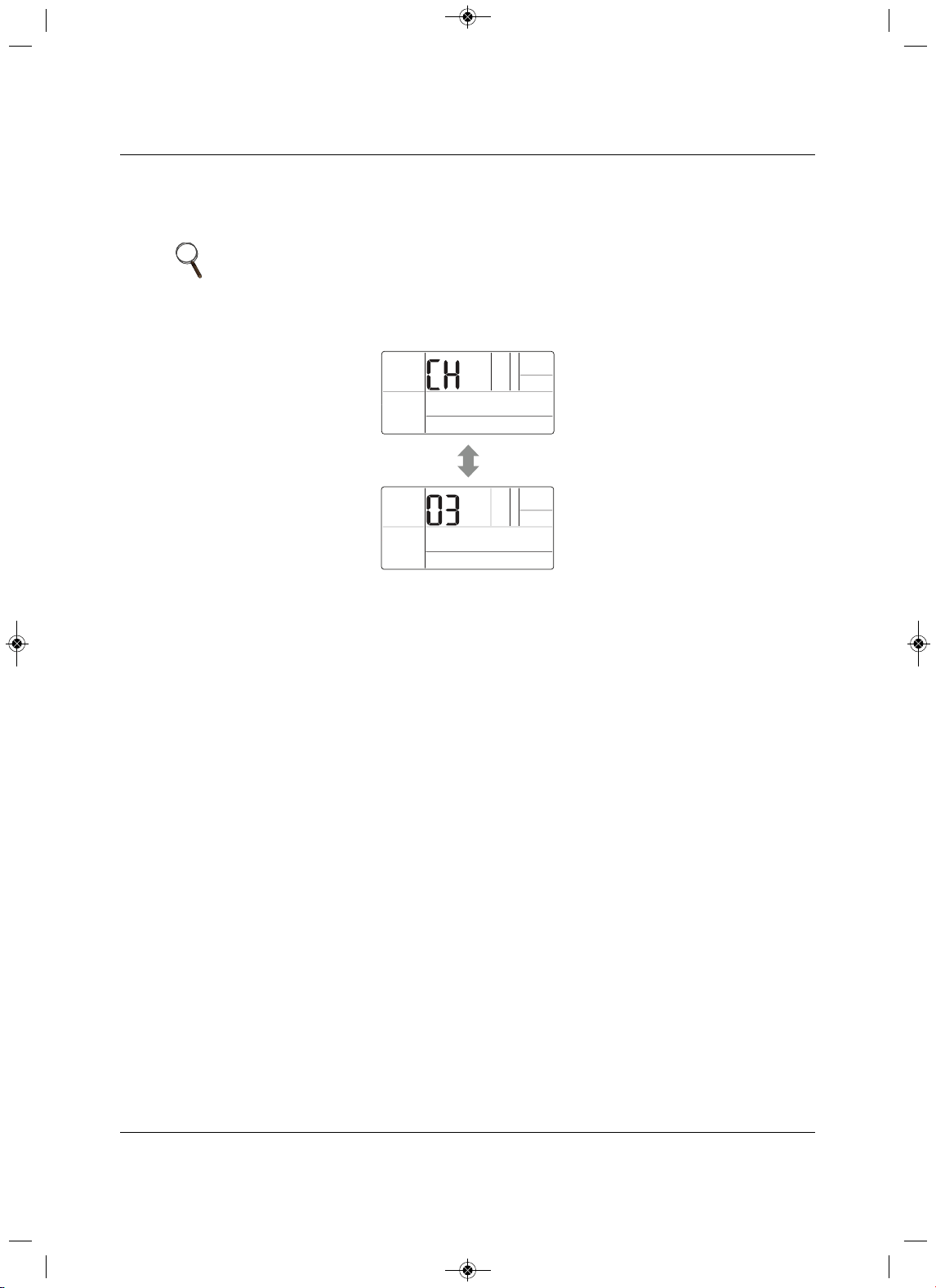
Troubleshooting
Liebert
®
SRC
™
User Manual 106
10.3 S elf-diagnosis at the Thermostat
If the unit has a problem, it will self-diagnose with Troubleshooting m ode and display “CH” and an error
code in the Temperature section of the display, Figure 10-1.
Figure 10-1 Error codes d
isplayed at the thermostat
10.4 Troubleshooting Error Codes at th e Indoor and Outdoor Units
Table 10-1 list the most-common error codes that you will see on these units. Some models may display
codes not listed here. Please contact service if a power-down/reboot does not correct the issue. Do not
attempt to fix the unit yourself
.
The error codes indicate different types of failures, assist in self-diagnosis, and helps track frequency of
occurrence. Figures 10-2 and 10-3 show where error codes display based on model number.
If two or more errors occur simultaneously,
the lower number displays first. When an error is resolved, the
number no longer displays.
Decoding Error Display for SRC18
Refer to Figure 10-2.
LED 1 blinks (green) to indicate the second, “ones” digit of the error code.
LED 2 blinks (red) to indicate the first, “tens” digit of the error code.
For example, if the error code is 21,
LED 1 blinks 1 time, and LED 2 blinks 2 times.
NOTE
Verify the thermostat function settings after recovery from an error. The
settings could have changed because of communication with the controller in
group mode.
MFL67502030 17. 7. 13. 오오 3:05 Page 116
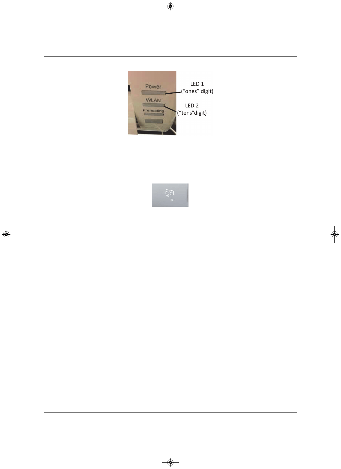
Troubleshooting
107 Liebert
®
SRC™ User Manual
Figure 10-2 Error-code display for SRC18
Decoding Error Display for SRC24 and SRC36
Refer to Figure 10-3.
The digital display blinks “CH” then the error number.
Figure 10-3 Error-code display for SRC24 and SRC36
MFL67502030 17. 7. 13. 오오 3:05 Page 117
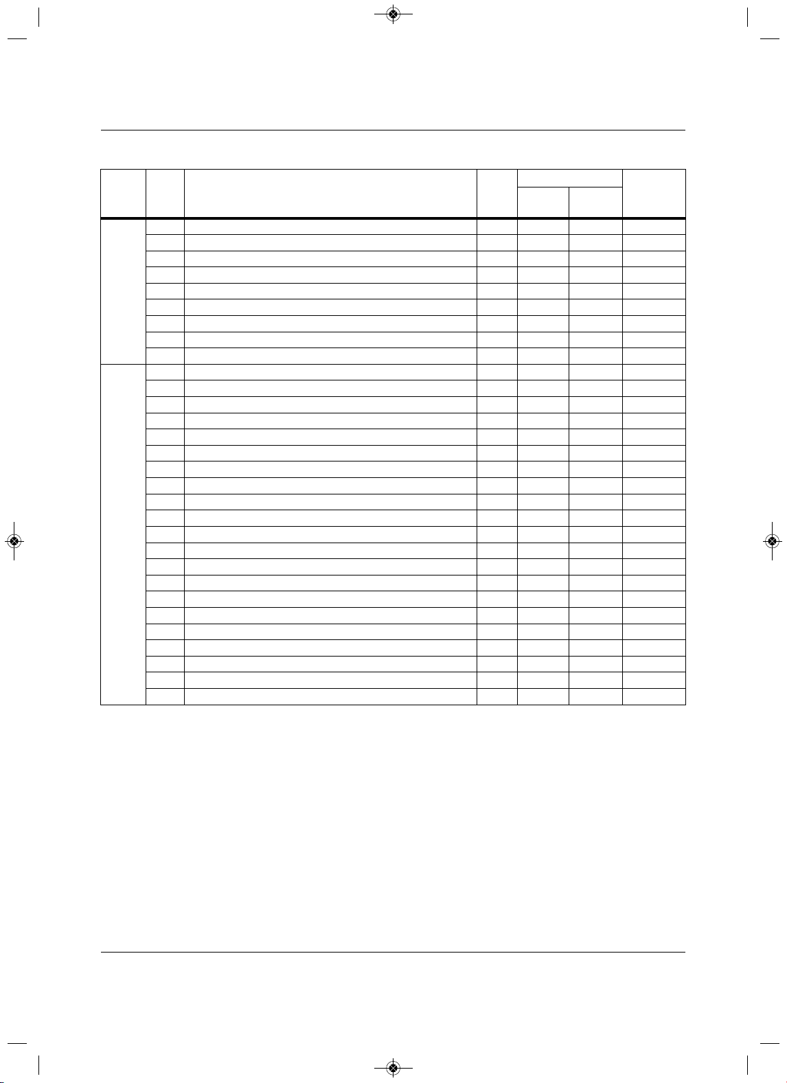
Troubleshooting
Liebert
®
SRC
™
User Manual 108
Table 10-1 Error Codes
Unit
Error
No.Description
Indoor
Unit
LED
SRC18 LED blinks
SRC24 and
SRC36
displays
LED 1
(2
nd
digit)
LED 2
(1
st
digit)
Indoor
1 Indoor unit room-temperature sensor error 9 1x — CH01
2 Indoor unit inlet pipe sensor error 9 2x — CH02
3Wired remote-control error 9 3x — CH03
4Float switch (optional) error 9 4x — CH04
5Communication error between indoor and outdoor unit 9 5x — CH05
6 Indoor unit outlet-pipe sensor error 9 6
x — CH06
9 Indoor unit EEPROM error 9 9x — CH09
10 Indoor unit BLDC motor fan lock 9 —1x CH10
12 Indoor unit middle pipe sensor error 9 2x 1x CH12
Outdoor
21DC Peak (IPM fault) 9 1x 2x CH21
22 CT 2 (Max CT) 9 2x 2x CH22
23DC Link Low/High Volt 9 3x 2x CH23
26DC Comp Position Error 9 6x 2x CH26
27 PSC Fault 9 7x 2x CH27
29Comp Phase Over-current 9 9x 2x CH29
32 Invert Compressor D-pipe Overheat 9 2x 3x CH32
38 Refrigerant Lea
k detection 9 8x 3x CH38
37 Exceed the Compression Ration Limit 9 7x 3x CH37
41D-pipe Sensor Error 9 1x 4x CH41
44 Outdoor Air Sensor Error 9 4x 4x CH44
45Cond. Out Pipe High 9 8x 4x CH45
51 Excess Capacity (Mismatching between In/Outdoor unit)
9 1x 5x CH51
53 Communication Error (IN-OUT) 9 3x 5x CH53
60 Outdoor EEPROM Check sum error 9 —6x CH60
61 Cond. Pipe High 9 1x 6x CH61
62 Heat Sink Sensor Temp. High 9 2x 6x CH62
65 Heat sink Th Error (open/short) 9 5x 6x
CH65
67 BLDC Motor Fan Lock 9 7x 6x CH67
72 Detect 4 Way Valve Transfer Failure 9 2x 7x CH72
93 Communication Error (IN-OUT) 9 3x 9x CH93
MFL67502030 17. 7. 13. 오오 3:05 Page 118
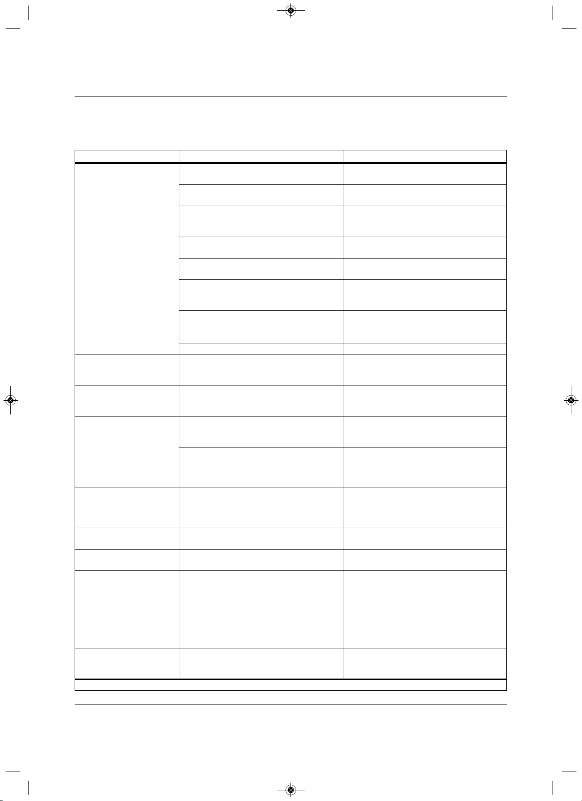
Troubleshooting
109 Liebert
®
SRC™ User Manual
10.5 Troubleshooting Table
Table 10-2 lists problems, possible causes, and a corrective action.
Table 10-2 Troubleshooting problems, causes and correction
Problem Possible Causes Corrective Action
Unit does not emit cool air
Air is not circulating properly.
• Make sure that there are not curtains, blinds,
or furniture blocking the front of the unit
.
The air filter is dirty.
•Clean the air filter once every 2 weeks. See
9.1, Cleaning the Air Filter, page 102.
The room temperature is too high.
• In summer, coolin
g the indoor air fully may
take some time. In this case, select Power
Cool to cool the indoor air quickly.
Cold air is escaping from the room.
• Make sure that no cold air is escaping
through ventilation points in the room.
The desired temperature is higher than the set
temperature.
•Set the desired temperature to a level lower
than the current temperature.
There is a heating source nearby.
• Avoid using
heat generators like electric
ovens or gas burners while the unit is
operating.
Fan Mode is selected.
•During fan mode, air blows from the unit
without cooling or heating the indoor air.
•S
witch the operation mode to cooling.
Outside temperature is too high. •The cooling effect may not be sufficient.
The fan speed cannot be
adjusted.
The Jet Mode or Auto Operation Mode is
selected.
• In
some operation modes, you cannot adjust
the fan speed. Select an operation mode in
which you can adjust the fan speed.
The temperature cannot be
adjusted.
The Fan Mode or Jet Mode is selected.
• In some operation modes, you cannot adjust
the temperature. Select an operation mode
in which you can adjust the temperature.
The unit stops during
operation.
The unit is suddenly turned off.
•The Timer Function may have timed-out,
which turns
the unit off. Check the
timer/schedule settings.
A power failure has occurred during operation.
•Wat for the power to come back. If you have
the Auto Restart function enabled, your unit
wi
ll resume in its last operation mode several
minutes after power is restored.
The indoor unit is still
operating even when the
power has been turned off.
The Auto Clean function is being operated.
• All the Auto Clean
function to continue
because it removes any remaining moisture
inside the indoor unit. If you do not want it to
continue, turn the unit off.
The air outlet on the indoor
unit is discharging mist.
The cooled air
from the unit makes mist.
•When the room temperature decreases, the
phenomenon will disappear.
Water leaks from the outdoor
unit.
In heating operation, condensed water drops
from the heat exchanger.
•This requires install
ing a drain hose under
the base pan. Contact the installer.
There is a noise or vibration.
A clicking sound cab be hard when the unit
starts or stops due to movement of the
reversing valve.
Creaking sound: T
he plastic parts of the indoor
unit creak due to sudden temperature
changes.
Flowing or Blowing sound: This is the flow of
the refrigerant through the unit.
•These are normal occurrences
. The noise
will stop.
The indoor unit gives off an
odor.
Odors (such as cigarette smoke) may be
absorbed into the indoor unit and discharged
with air flow.
• If the smell does not disappear, wash
the air
filter. If this does not work, contact service to
clean the heat exchanger.
Depending on mode, some functions may not be supported.
MFL67502030 17. 7. 13. 오오 3:05 Page 119
Troubleshooting
Liebert
®
SRC
™
User Manual 110
10.6 Refrigerant Leaks
ASHRAE Standards 15-2010 and 34-2010 offer guidelines that address refrigerant safety and the
maximum allowable concentration of refrigerant in an occupied space. Refrigerant will dissipate into the
atmosphere, but a certain volume of air is required for this to occur safe
ly. For R410A refrigerant, the
maximum allowable concentration is 0.026 lbs/ft
3
per 1,000 ft
3
of air in an occupied space. Buildings with
24-hour occupancy allow half of that concentration.
1
ASHRAE Standards 15 and 34 assume that if a system develops a leak, its entire refrigerant charge will
dump into the area where the leak occurs. To meet ASHRAE Standards 15 and 34, calculate the
refrigerant concentration that may occur
in the smallest room volume on the system, and compare the
results to the maximum allowable concentration number.
1
A lso consult state and local codes with regard to
refrigerant safety.
To calculate the potential refrigerant concentration leve l (RCL):
1. Measure the occupied space dimensions (in feet).
2. C alculate the cubic foot volume of air in the smallest occupied space. (To
obtain a detailed overview of
the RCL, perform the same calculations to the second smallest zone, the third smallest zone until the
RCL is obtained for all zones. Also, pay special attention to areas such as basements, etc.,
where
refrigerant cannot dissipate easily.)
3. Divide the refrigerant change of the Liebert SRC serving the area in pounds by the results of Step 1.
The unit does not emit warm
air.
When Heating Mode starts, the vane is almost
closed and no air comes out, even thought the
outdoor unit is operating.
•This is normal. Please wait until the unit has
generated enough warm air to blow through
the indoor
unit.
The outdoor unit is in Defrosting Mode.
• In Heating Mode, ice/frost builds up on the
coils when the outside temperature falls.
This function removes the layer of frost on
the coil and should finish in approximately
15 minutes.
Outside temperature is too low. •The heating effect may not be sufficient.
!
WARNING
Risk of exposure to excessive refrigerant concentration and oxygen depletion. Can cause illness
or injury. If the unit is installed in a small improperly or non-ventilated space, take measures to
prevent the refrigerant concentration from exceeding safety limits in the event of a
refrigerant leak.
Verify the maximum refrigerant concentration level in the space where the indoor unit will be
mounted meets the concentration limit for the application.
NOTE
Take appropriate actions at the end of HVAC equipment life to recover,
recycle, reclaim or destroy R410A refrigerant according to applicable US EPA
rules.
Table 10-2 Troubleshooting problems, causes and correction (continued)
Problem Possible Causes Corrective Action
Depending on mode, some functions may not be supported.
MFL67502030 17. 7. 13. 오오 3:05 Page 120

Troubleshooting
111 Liebert
®
SRC™ User Manual
4. If the calculation indicates that the potential refrigerant concentration level is higher than the allowed
RCL, increase the cubic volume of the smallest occupied space or modify the piping system design.
5. The allowable RCL limit for most applications
must be equal to or less than 0.026 lbs/ft
3
. In special
occupied spaces, however, such as hospitals and nursing homes where occupants may have limited
mobility, the allowable RCL limit is cut in half. See ASHRAE Standard 34-2007 and local codes for
detailed information.
1
Figure 10-4 Refrigerant Concentration Limit (RCL) Calculations Equati on
1
American Society of Heating, Refrigeration and Air Conditioning Engineers, Inc. (ASHRAE). Atlanta, GA. ASHRAE, Inc.
Information about ASHRAE Standard 15-2010 / 34-2010 and addenda current as of the date of this publication.
Amount of
Factory-Charged
Refrigerant per
Outdoor Unit
Amount of
Additional
Refrigerant
Trim Charge
Total System
Refrigerant
Charge
+ =
RCL (lbs./ft
3
) =
Total System Refrigerant Charge (lbs.)
Volume of Smallest Occupied Space (ft
3
)
MFL67502030 17. 7. 13. 오오 3:05 Page 121

Troubleshooting
Liebert
®
SRC
™
User Manual 112
Page intentionally left blank.
MFL67502030 17. 7. 13. 오오 3:05 Page 122

MFL67502030 17. 7. 13. 오오 3:05 Page 123
Technical Support / Service
Web Site
www.liebert.com
Monitoring
800-222-5877
Outside North America: +00800 1155 4499
Single-Phase UPS & Server Cabinets
liebert.upstech@emerson.com
800-222-5877
Outside North America: +00800 1155 4499
Three-Phase UPS & Power Systems
800-543-2378
Outside North America: 614-841-6598
Thermal Management Systems
800-543-2778
Outside the United States: 614-888-0246
Locations
United States
1050 Dearborn Drive
P.O. Box 29186
Columbus, OH 43229
Europe
Via Leonardo Da Vinci 8
Zona Industriale Tognana
35028 Piove Di Sacco (PD) Italy
+39 049 9719 111
Fax: +39 049 5841 257
Asia
7/F, Dah Sing Financial Centre
108 Gloucester Road, Wanchai
Hong Kong
852 2572220
Fax: 852 28029250
While every precaution has been taken to ensure the accuracy and completeness of this literature, Liebert Corporation assumes no responsibility and disclaims
all liability for damages resulting from use of this information or for any errors or omissions.
© 2016 Liebert Corporation
All rights reserved throughout the world.
Specifications subject to changewithout notice.
® Liebert is a registered trademark of Liebert Corporation. All names referred to are trademarks or registered trademarks of their respective owners.
Emerson Network Power
www.emersonnetworkpower.com
SL-11055_REV0_6-16
590-1318-501A
P/NO : MFL67502030
MFL67502030 17. 7. 13. 오오 3:05 Page 500

