Loading ...
Loading ...
Loading ...
The gas must be connected to the appliance according to standard
and the provisions in force.
•When the appliance left the factory, it was regulated for the gas type
stated on the adhesive info label near the gas inlet at the back of the
appliance.
Make sure that you are using the gas stated on the label. If it is a
different type of gas, follow the instructions in the chapter on
conversion to different gas types'.
•Make sure that gas supply pressure is that given in the gas type
category table (Last 3 pages in this user manual) in order to achieve
maximum efficiency and lowest consumption. If the gas pressure is
different, a proper gas regulator should be used on the gas inlet. The
use of a gas regulator complying with the standards for LPG is
allowed.
Connection with a Solid or Flexible Metal Pipe
•The gas supply can be connected by a proper flexible stainless steel
pipe according to the safety standards in force. In this case, there will
be no further need to move the appliance. The gas inlet connector of
the appliance is Gc ½.
Connection with a Flexible Non-metallic Pipe
•If the gas connection is in a position where it can be switched on and
off when required, a flexible pipe complying with the standards in force
can be used. The flexible pipe must be firmly fixed with a clamp.
•The flexible pipe can be connected as follows:
•Since the flexible pipe will be placed behind the oven, it should be
exposed to temperatures no higher than 30ºC at any point.
•The length should be no longer than 150 cm.
•It must not be exposed to steam.
•No folding, bending or tension is allowed.
•It should be protected against sharp or piercing objects.
•It must be accessible in order to allow for periodic inspection.
•The flexible pipe must be checked as follows to guard against wear
over time:
•Check that there are no cracks, cuts or burned spots on or at the ends
of the pipe.
•The material must maintain its flexibility . Excessive rigidity is not
allowed.
•There must be no rust on the clamps.
•It should be replaced in any case after no more than 5 years' usage.
Check all connections for leaks with a soapy substance
after the installation is completed. Do not use a flame
for to check gas leaks.
RIGHT
FLEXIBLE GAS PIPE LINE
ELECTRICAL CABLE
WRONG
FLEXIBLE GAS PIPE LINE
ELECTRICAL CABLE
2.7. GAS CONNECTION
For the cookers below written adjustment have to be done by qualified
technician.
Follow the steps given below to convert the appliance from the factory
set up to that for a different gas type.
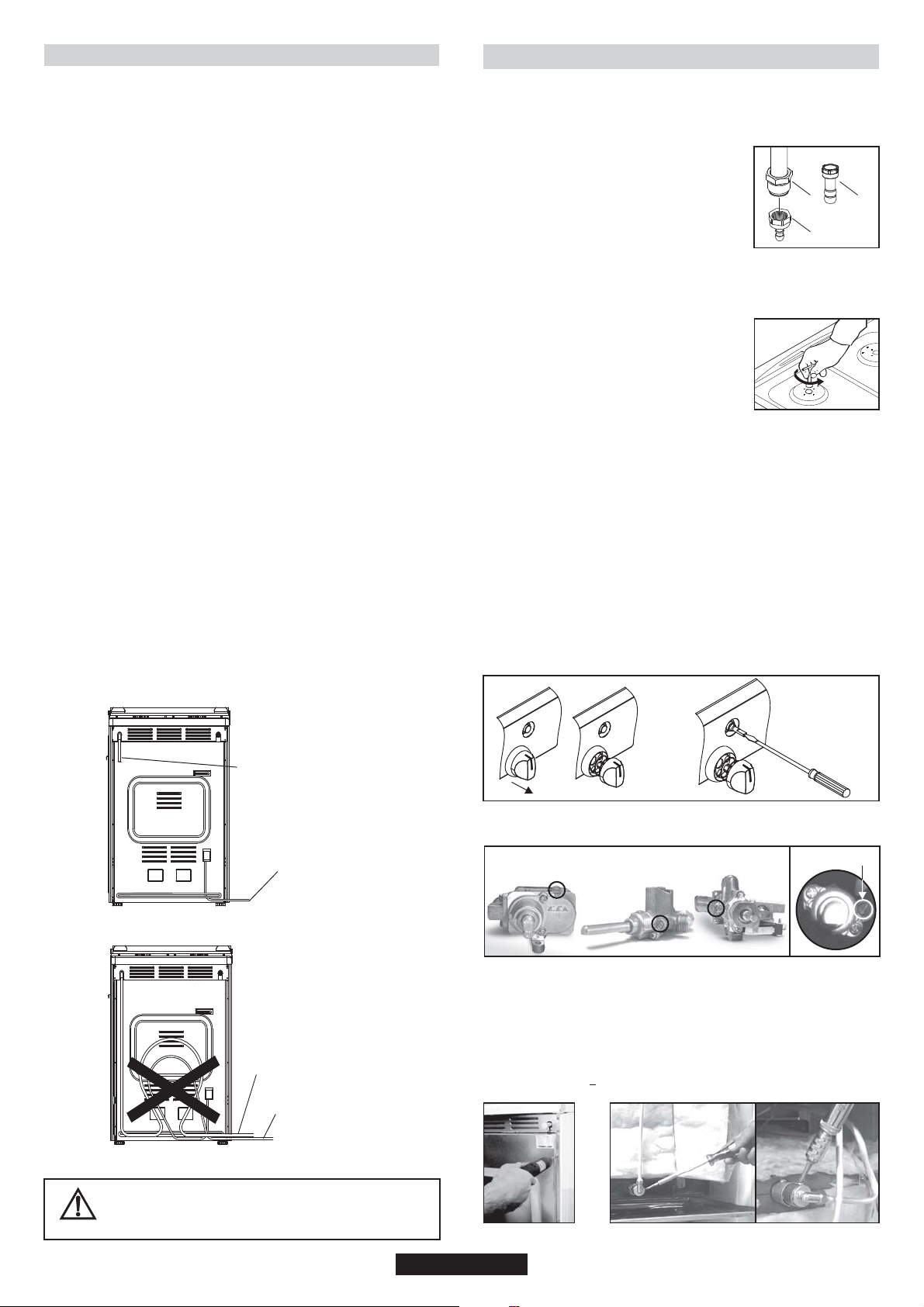
Cookers are adjusted NG and connection type
is cylindric (1). For hose type NG connection,
hose adapter (2) can be fixed to cylindrical
adapter with seal.
For LPG connection, LPG hose adapter (3) can
be fixed to cylindric adapter with seal.
Adjustments and changing injectors
Changing Injectors
•Remove grates.
•Remove burner caps and burners.
•Remove injectors by using a 7 mm wrench, then screw on the correct
injector selected from gas type category table
(last 3 pages in this user manual) according to
the gas to be used.
•Follow the above steps in the reverse order
after completing the assembly of the new
injector.
Stand by Adjustment
Stand by adjustment for the cookers
without safety devices and with safety devices and button
ingition
•Turn the burner control knob to the small flame position and remove
the knob.
•If conversion from natural gas to LPG is required, turn clockwise the
by-pass screw of the gas valves with a screw driver to their final
position.
•If conversion from LPG to natural gas is required, turn anti-clockwise
the by-pass screw of the gas valves with a screw driver till a smaller
flame of ¼ size is obtained.
•After completing the adjustment, insert the knobs again.
•Check the adjustment by turning the burner control knob quickly from
maximum to minimum position. If the flame does not go out, it means
that the adjustment is correct.
•For safety devices, idle flame setting can be done with screw on valve
body. If there is ignition on the knob for idle flame setting cooktop,
toplid and panel must be removed.
2
3
2.8. CONVERSION FOR DIFFERENT GAS TYPES
1
By-pass screw for the burner
without safety
devices
Gas Oven
•Remove rear cover ( Figure3)
•Remove injector adapter.(Figure 4)
•Remove injectors by using a 7 mm wrench, then screw on the correct
injector selected from gas type category table (last 3 pages in this
user manual) according to the gas to be used. (Figure 5)
•Follow the above steps in the reverse order after completing the
assembly of the new injector.
•Burner Gap is 4.5 + 0.3 mm for NG and LPG (Figure 6)
Figure3 Figure4
safety devices
•For thermostat valve idle frame setting cooktop, top lid and panel
must be removed.
19 GB
Loading ...
Loading ...
Loading ...