Loading ...
Loading ...
Loading ...
16
The remote thermostat-Class 2 option (Mode 6 in the
auxiliary control setting) must be turned ON to enable
remote thermostat control. Refer to installation instructions
packaged with the chassis.
Please see page 57 for installation recommendations
for the remote thermostat wiring. Compatibility of other
thermostats considered for use with GE Zoneline units
is the responsibility of the customer.
The control voltage on the remote control conductors is 24
volts AC. The AC voltage may not be compatible with some
solid-state thermostats.
The fan speed for the 4100 Series in remote thermostat
operation is selected by the connection of the fan wire from
the thermostat to either the HIGH or LOW terminal on the unit.
See the sketch of the unit terminals below for the location of
the HIGH and LOW fan-speed terminals. Operating the unit in
low fan speed reduces the operating sound level of the unit.
Freeze Sentinel and Heat Sentinel remain operational if the
unit is connected to a remote thermostat. The unit may be
connected to a Central Desk Control (CDC) system and
controlled with a remote thermostat when the CDC system
has the unit in operation. See page 15 for additional
information on the CDC system.
Unit temperature-limiting settings are not functional when
unit is connected to a remote thermostat.
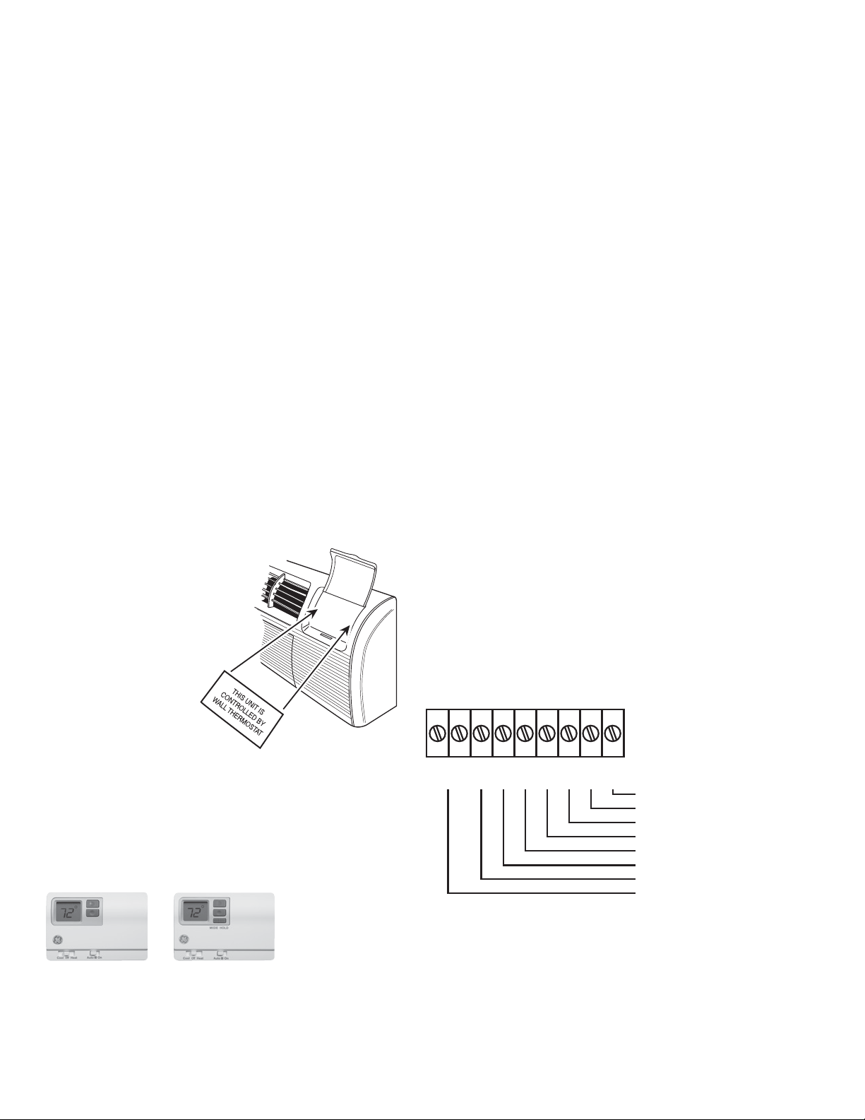
Field Wiring Terminal
R — 24V AC
GL — Low-Speed Fan
GH — High-Speed Fan
B — Not Used on 4100
Y — Compressor
W — Heater
C — Common
REMOTE THERMOSTAT CONTROL
In some installations, control of the operation of the unit
at a location remote from the unit itself may be desired. A
unit mounted high in the wall or over a door, for instance,
where the unit-mounted controls are inaccessible, can be
connected to a wall-mounted thermostat. Other installations
may use remote thermostat control for design or performance
enhancement. The unit is connected to the thermostat by
low-voltage wiring which permits the operation of the unit to
be selected and the temperature sensed at the thermostat.
Important Notes: Remote thermostat wiring should NOT be
run through the wall case. Thermostat wiring should exit the
wall below the unit and enter the unit between room cabinet
and chassis. Wire molding may be used to hide thermostat
wiring. If a sub-base is used, the thermostat wiring may be
concealed by the sub-base. Thermostat wiring should NOT
be run parallel to line voltage wires since induced current
may cause erratic operation.
All Zoneline
®
4100 and 6100 Series units are adaptable to
Class 2 remote low-voltage thermostats. The only additional
field-supplied components are the remote thermostat and
wiring necessary to connect it.
The controls on the unit are not functional when the remote
control function is used.
RAK806 Universal Control Cover Label
When a Zoneline unit is using a remote thermostat control,
the RAK806 Universal
Control Cover Label is
recommended. The
RAK806 is only
available in a
package of 10 labels.
The label is placed
over the control panel
to direct the user to
the wall thermostat
for operation of the
Zoneline unit.
Resistance Heat Models
The Zoneline 4100 resistance heat units may be connected
to a single-stage thermostat designed for use with cooling
with electric heat systems. GE offers two thermostats
compatible with the 4100 Series unit.
R
GL
GH
B
Y
W
C
Common
White — Heater
Yellow — Compressor
Black — Not Used On 4100
Green — High-Speed Fan
Green — Low-Speed Fan
Red — 24V AC
CDC Terminal
CDC
RAK164D2 —
a solid-state
digital thermostat
requiring five
connection wires.
RAK164P2 —
a solid-state digital
programmable
thermostat
requiring five
connection wires.
Loading ...
Loading ...
Loading ...