Loading ...
Loading ...
Loading ...
4
Front Panel
Power Switch
The power switch turns the amplifier on and off.
When the Sonance logo on the power switch is lit bright white, the
amplifier has power and is turned ON and ready to operate.
When the Sonance logo is slightly dimmed the amplifier is in to
sleep/all channels asleep/sleep mode active mode.
When the Sonance logo on the power switch is blinking white, the
amplifier power supply is in thermal protection. The channel LEDs
will also light red when the power supply is in thermal protect mode.
NOTE: Upon initial power up there will be an approximately 9-12
second boot up cycle. This is normal.
Input/Output Lights
When each channel is active, the LED will light green as long as a
signal is present.
When the LED blinks red, this is an indication that the channel is
being overdriven.
When the LED lights are solid red this is an indication the amplifier
is in protect mode. While in protect mode, the LED lights will
periodically light green to retest the output to determine if the short
has been removed. Protect mode could be caused by a short in the
wire, overheating of the amplifier or possibly an internal problem
with the amplifier.
NOTE: WHEN ANY OF THE LEDS ARE LIT RED TURN THE
AMPLIFIER OFF IMMEDIATELY. DETERMINE THE CAUSE OF THE
PROBLEM BEFORE TURNING THE AMPLIFIER ON.
Volume Level Control
Each channel on the amplifier has volume adjustments found in the
SONARC software. Output volume can be adjusted in SONARC
or from the front panel recessed volume controls. Output volume
will reflect the option last adjusted. The DSP 8-130 MKII amplifier
ships at the +12 or maximum volume level.
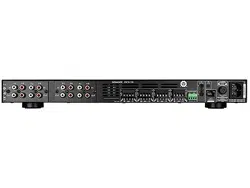
Rear Panel
Line Inputs/Loop Outputs
The DSP 8-130 MKII amplifier has four pair of LINE INPUTS and four
pair of Loop OUTPUTS.
The loop outputs are non buffered; the maximum number of
amplifiers that can be looped together will depend on the output
capability of your source component
Speaker Connections
The removable block connectors used on the Sonamp amplifiers will
accept up to 12 gauge wire.
Follow the connection layout on the rear panel of the amplifier.
Make sure no bare wires come in contact with the amplifier chassis.
When bridging channels, use the two outside connections on each
connector. The positive wire from the speaker should be on the
left side connection and the negative connection should be on the
right side.
Auto On - Voltage In/Out Trigger
The Sonamp amplifiers can be turned on and off using 3-30 volts AC
or DC. The Voltage Output supplies a 12 volt DC signal to control
additional amplifiers or other equipment. The included red wire is
to prevent the amp from accidentally entering sleep mode during
setup. Remove the red wire when using voltage trigger.
IR Control
IR control is accomplished via the IR control In/Out jacks. IR controls
global On/Off, group volume, muting and input source selections.
Connectivity can be seen with IR status light.
IP Control
IP control is accomplished via the RJ-45 input. IP controls power
On/Off, volume, muting and input source selections for either
global control or group control. For more detail see network
connection instructions.
AC Fuse Holder
To replace the fuse, unplug the power cord from the Power Cord
Connector and use a screwdriver to remove the fuse holder.
DSP 8-130 MKII - 15 amp AC (T15-AL)
CAUTION: FOR CONTINUED PROTECTION AGAINST FIRE,
REPLACE THE FUSE WITH ONLY THE SAME TYPE AND RATING.
Power Cord
The Sonamp amplifiers feature removable IEC power connectors.
Plug the female end of the power cord into the Power Cord
Connector on the amplifier rear panel and plug the male end into a
grounded wall socket.
DO NOT plug the amplifier’s power cord into a convenience outlet
on any other audio or video component. If you need to use an
extension cord, use only a heavy duty (14-GAUGE OR LARGER)
extension cord to avoid starving the amplifier of the current
necessary for full operation.
FIGURE 3: SONAMP DSP 8-130 MKII AMPLIFIER FRONT PANEL VIEW FIGURE 5: SONAMP DSP 8-130 MKII AMPLIFIER REAR PANEL VIEW
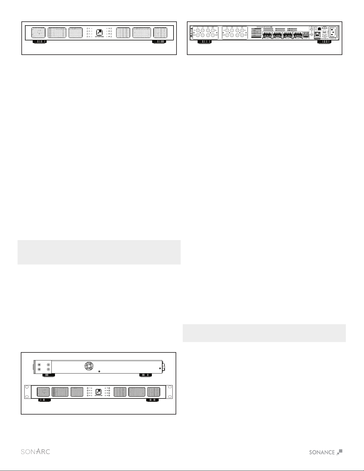
Rack Ear Installation DSP 8-130 MKII
The DSP 8-130 MKII ships with two rack ears. Unscrew the four
Phillips head screws (M4 x 0.7 pitch x 10mm long) found on each side
of the left and right forward section of the amplifier. Use these screws
to connect the included rack ears to the amplifier (see Figure 4).
FIGURE 4: RACK EAR INSTALLATION DSP 8-130 MKII
SIDE VIEW RIGHT
FRONT VIEW
Shelf Mounting
If shelf mounting, attach the four included feet by screwing them into
the threaded openings, on the bottom chassis, no tool is required.
Loading ...
Loading ...
Loading ...