
Owner’s Manual
E120v1.4
1
BaseSerialNumber:E_____________
ConsoleSerialNumber:_____________
PurchasedDate:___/___/______
Dealer’sName:__________________________
Pleaseregisteryourproductsat:
https://www.bodycraft.com/product-registration/
E1200Elliptical
Adjustable-Stride
OpenyourCamera
Appandpointitat
theQRCode
To see in
FULL COLOR
& addition information,
scan this QR code
SerialNumber

CongratulationsandWelcometotheBODYCRAFTFamily
ThankyouforselectingBODYCRAFT.Yourchoicereflectsawiseinvestmentinyouandyour
facility.Wehopeyouuseitformanyhealthyyears!
BODYCRAFT offers a complete array of high-quality fitness equipment. Please refer to our website at
www.bodycraft.com to view more ways to enhance your lifestyle.
Your BODYCRAFT machine has all the quality and design elements to make your workout extremely efficient
and comfortable. Your new unit is a serious cardio machine that will keep you motivated, challenged and
within reach of your fitness goals. Strength & cardiovascular training is vital for all ages which will provide an
effective workout, producing results that will encourage you to reach your fitness goals and maintain the
body you have always wanted.
Spending15to30minutesaday,threetimesaweek,isallyouneedtostartseeingthebenefitsof
aregularexerciseprogram.
As a premium exercise equipment manufacturer, we are committed to your complete satisfaction. If you
have questions, suggestions or find missing or damaged parts, we guarantee your complete satisfaction
through our authorized dealer network or by contacting us directly. Please call your local dealer or
BODYCRAFT.
BODYCRAFT (a division of Recreation Supply, Inc.)
7699 Green Meadows Dr.
Lewis Center, OH 43035
Phone: 800-990-5556 9 am - 5 pm EST Email: service@bodycraft.com
Proofofpurchasemustbesuppliedtovalidatewarrantyandtheproductmusthavebeen
registeredwithBODYCRAFTviaonlineatwww.bodycraft.comorbycalling800-990-5556
or740-965-2442M-F9a.m.-5p.m.EST.
Forpartsorders,owner’smanuals,software
updatefiles,exerciseguidesandcontact
informationscanthisQRcode.
Orgoto:
https://www.bodycraft.com/customer-support

Page
ProductSafetyInformation
FCCInformation………………………………………………………………5
ProductSafety…………………………………………………………….6-7
ProductOverview
ProductOverviewComponents&ToolsforAssembly.…………………...8
HardwareIdentificationChart..................................................….………..9
AssemblyParts……………………………………………………………….10
ShippingBoxesandWhat’sInsideEachOne…………………………..11
HowAssembletheElliptical
PreAssemblyTips…………............................................………….12
ProductAssemblyInstructions..........................................………….12-28
OperationInstructions
OperatingInstructions……………………………………………………..29
CleaningyourElliptical..……………………………………………………30
HeartRateMonitoringGrips&WirelessReceiver……………………....31
ErraticHeartRateReadings&ExerciseTips…………………………….32
InstallationChecklist……………………………………………………….33
EnergySavingfunction:Theseconsolesareequippedwithpowersavingfunction.
Thismeansafter10minutesofinactivityitwillautomaticallypoweroff.Pressany
keyontheconsoleforX-9LCDortouchthescreenforX-10TS/X-16TStowakeup
theconsolefrompowersavemode.
3
TableofContents
4
5-6
7
8
9
10
11
12-29
30-31
32
33
34
35

Caution:
Pleasenotethatchangesormodificationsnotexpresslyapprovedbythepartyresponsiblefor
compliancecouldvoidtheuser'sauthoritytooperatetheequipment.
ThisdevicecomplieswithPart15oftheFCCRules.Operationissubjecttothefollowingtwoconditions:
(1)Thisdevicemaynotcauseharmfulinterference,and(2)thisdevicemustacceptanyinterference
received,includinginterferencethatmaycauseundesiredoperation.
NOTE:
ThisequipmenthasbeentestedandfoundtocomplywiththelimitsforaClassBdigitaldevice,
pursuanttoPart15oftheFCCRules.Theselimitsaredesignedtoprovidereasonableprotectionagainst
harmfulinterferenceinaresidentialinstallation.Thisequipmentgenerates,usesandcanradiateradio
frequencyenergyand,ifnotinstalledandusedinaccordancewiththeinstructions,maycauseharmful
interferencetoradiocommunications.However,thereisnoguaranteethatinterferencewillnotoccurina
particularinstallation.Ifthisequipmentdoescauseharmfulinterferencetoradioortelevisionreception,
whichcanbedeterminedbyturningtheequipmentoffandon,theuserisencouragedtotrytocorrectthe
interferencebyoneormoreofthefollowingmeasures:
Reorientorrelocatethereceivingantenna.
Increasetheseparationbetweentheequipmentandreceiver.
Connecttheequipmentintoanoutletonacircuitdifferentfromthattowhichthereceiverisconnected.
Consultthedealeroranexperiencedradio/TVtechnicianforhelp.
FCCCAUTION:Changesormodificationsnotexpresslyapprovedbytheparty
responsibleforcompliancecouldvoidtheuser’sauthoritytooperatethisequipment.
Page
Maintenance&Repairs
InformationNeededPriortoContactingCustomerSupport………………34
CircuitDiagram………………………………………………………………...35
PartsLists………..………….………………………………………….….36-37
PartsExplodedViews………………………………….…………….……38-39
Warranty
ProductWarranty..........................................................….……..….……...40
ProductWarrantyRegistration............................................….…..………41
ContactUsInformation………………………………………………………..42
TableofContents
FCCInformation
36
37
38-39
40-41
42
43
44
4

SafetyandWarnings
Thereisariskassumedbyindividualswhousethistypeofequipment.
Amoment’slackofattentioncanresultinanaccident,ascanfailureto
observecertainsimplesafetyprecautions.
Read,studyandunderstandtheAssemblyInstructionsandallthewarninglabelsonthis
product.Furthermore,itisrecommendedtofamiliarizeyourselfandotherswiththeproper
operationandworkoutrecommendationsforthisBODYCRAFTproductpriortouse.
● Werecommendthattwopeoplebeavailableformovingandassemblyofthisproduct.
● KeepchildrenawayfromtheElliptical.DonotallowchildrentouseorplayontheElliptical.
● KeepchildrenandpetsawayfromtheEllipticalwhenitisinuse.
● Itisrecommendedthatyouplacethisexerciseequipmentonanequipmentmat.
● SetupandoperatetheEllipticalonasolidlevelsurface.DonotpositiontheEllipticalon
looserugsorunevensurfaces.
● InspecttheEllipticalforwornorloosecomponentspriortouse.
● Tighten/replaceanylooseorworncomponentspriortousingtheElliptical.
● Alwayschoosetheworkoutwhichbestfitsyourphysicalstrengthandflexibilitylevel.Know
yourlimitsandtrainwithinthem.
● Alwaysusecommonsensewhenexercising.
● Keephands,limbs,looseclothingandlonghairwelloutofthewayofmovingparts.
● DonotwearlooseordanglingclothingwhileusingtheElliptical.
● Neverexerciseinbarefeetorsocks;alwayswearcorrectfootwear,suchasrunning,
walking,orcross-trainingshoes.
● Becarefultomaintainyourbalancewhileusing,mounting,dismounting,orassemblingthe
Elliptical.Lossofbalancemayresultinafallandseriousbodilyinjury.
5

SafetyandWarnings
● KeepbothfeetfirmlyandsecurelyontheFootPedalswhileexercising.
● ThisEllipticalshouldnotbeusedbypersonsweighingover400pounds/181kgs.
● TheEllipticalshouldbeusedbyonlyonepersonatatime.
● Makesurethatadequatespaceisavailableforaccesstoandpassagearoundthe
Elliptical;keepatleastadistanceof3feetfromanyobjectwhileusingthemachine.
● ThisEllipticalisdesignedforcommercialandhomeusage.
● Maintenance:
○ Replaceanydefectivecomponentsimmediatelyand/orkeeptheequipmentoutofuse
untiltheequipmentiscompletelyrepaired.
○ Cleanseat,plasticandframeonaregularbasis.Werecommendwarm,soapywater.
Donotuseharshorabrasivechemicals.
WARNING:Beforeusingthisproductoranyexerciseorconditioningprogram,youshouldconsult
withyourpersonalphysiciantoseeifyourequireacompletephysicalexam.Thisisespecially
importantifyouhaveneverexercisedbefore,arepregnant,orsufferfromanyillness.Followyour
physician'srecommendationsindevelopingyourownpersonalfitnessprogram.
READANDFOLLOWTHESAFETYPRECAUTIONS.FAILURETOFOLLOWTHESE
INSTRUCTIONSCANRESULTINSERIOUSBODILYINJURY.
6
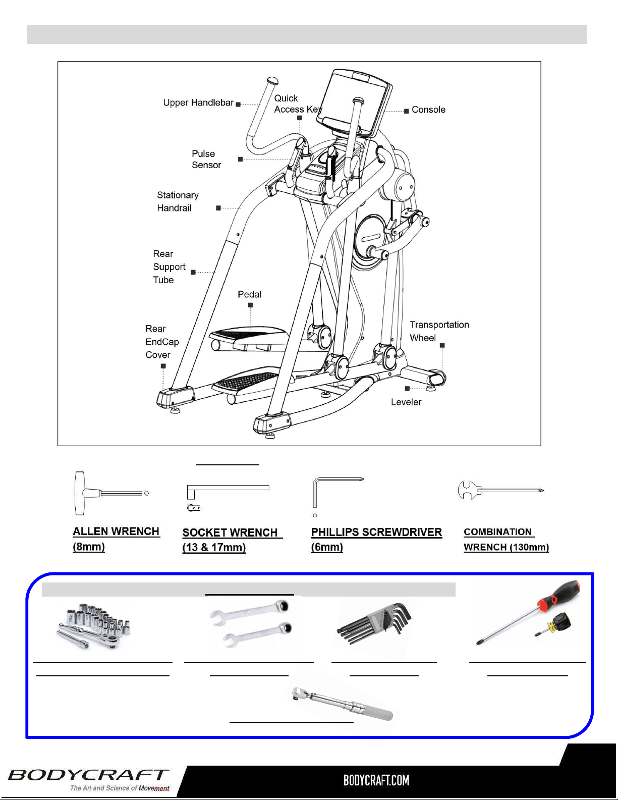
ProductOverviewComponentsandToolsforAssembly
THEFOLLOWINGTOOLSAREINCLUDEDFORASSEMBLY:
7
THEFOLLOWINGTOOLSARERECOMMENDEDFOREASIERASSEMBLY:
SOCKETSET⅜drivew/3“&6”
EXTENSIONfor13mm&17mm
OPEN&CLOSEDWRENCHES
for13mm&17mm
ALLENWRENCHESSET
4mmto10mm)
PHILLIPSSCREWDRIVERS
#2w/MagneticTIP
TORQUEWRENCH⅜DRIVE
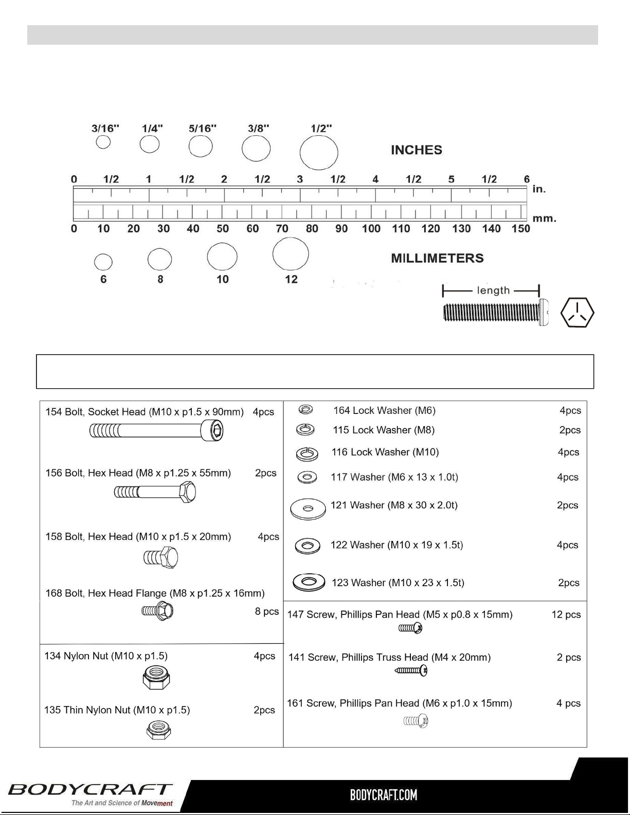
Unpacktheboxinacleararea.UsetheListofHardwarebelowtocheckthecontentsofthehardwarekit.This
chartisprovidedtohelpidentifythehardwareusedintheassemblyprocess.Placethewashers,theendofbolts,
orscrewsonthecirclestocheckforthecorrectdiameter.Usetherulertocheckthelengthoftheboltsand
screws.
NOTICE:Thelengthofallboltsandscrewsexceptthosewithflatheadsis
measuredfrombelowtheheadtotheendoftheboltorscrew.Flat
headboltsandscrewsaremeasuredfromthetopoftheheadtothe
endoftheboltorscrew.
Pleasereviewbelowtoknowthecontentofthehardwarekit.
Ifapartisnotinthehardwarebag,checktoseeifithasbeenpreassembled.
HardwareIdentificationChart
8
4
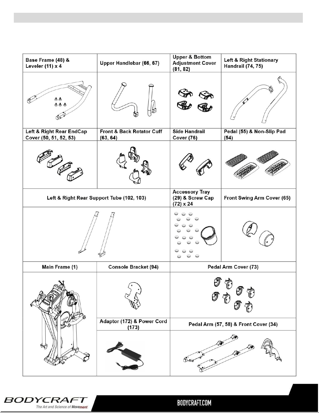
Unpacktheboxinacleararea.FollowtheListofAssemblyPartsbelowtocheckandmakesureallassemblypartsare
presentandingoodcondition.Donotdisposeofthepacking materialuntiltheassemblyprocessiscompleted.Assembly
toolsandhardwarekithaveincludedforyoutousewhenassemblingtheproduct
AssemblyParts
(12DC / 5A)
9
(5each)
BODYCRAFTreservestherighttomakeimprovementsatanytimewhichmayaffect
color,parts,materials,size,weight,oranyotheraspect.
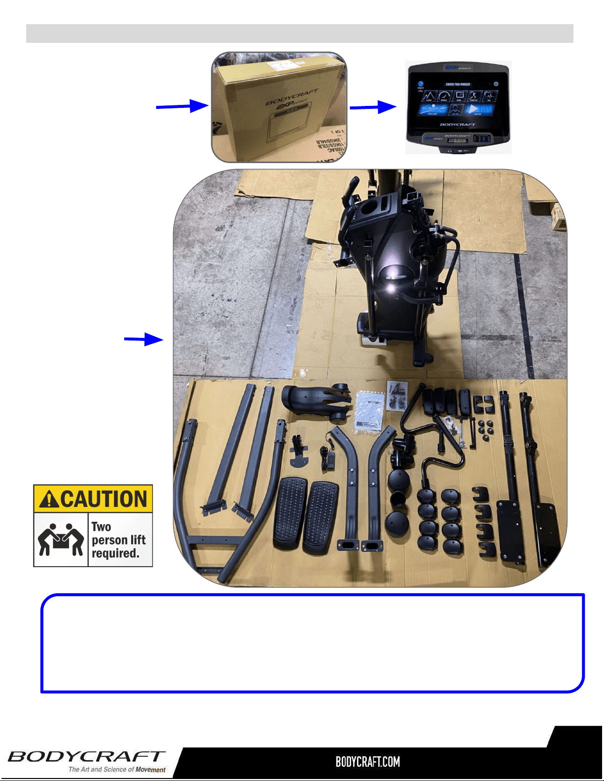
ShippingBoxesandWhat’sInsideEachOne
LargeBox2of2
SmallBox1of2
1each@9lbs
19”x6.25”x5”
(Includestheconsole
modelthatwasordered)
1each@380lbs
37”x34”x68.5”
TIP:Placeallpartsfromtheboxinaclearedareaandpositionthemonthefloorinfrontofyou.
Removeallpackingmaterialsfromyourareaandplacethembackintothebox.Donotdisposeofthe
packingmaterialsuntilassemblyiscompleted.
Readeachstepcarefullybeforebeginning.
10
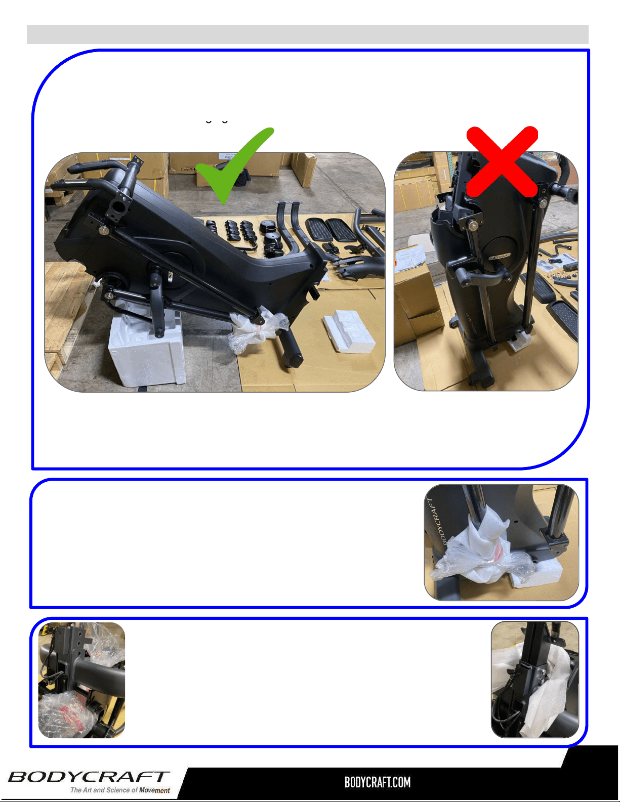
ProductAssembly-PreAssemblyTips
PREASSEMBLYTIP#1–UnPacking“TheMonster”(E1200&E1000).
Onceyouhavetakenallthepartsandmainframeoutoftheshippingbox,placethemain
frameforwardonpackagingfoam.ONLYRESTONMETALFRAMENOTPLASTIC.
VerystableandsafetostarttheAssemblySTEPS.
Thiswillensureahappierandlongerlifeoratleast
duringtherestoftheassemblyprocess!
Notstableandcaneasilyfall
over.DONOTattempttill
afterlowerframeisattached.
PREASSEMBLYTIP#2–Wrappingthemovingarmsends.
ThebottomofbothmovingarmsWILLswingbackandforthduring
theassemblySTEPS,potentiallycausingdamagetomachineorthe
assemblytech.Takesomeofthepackagingwithrubberbandsorits
shippingtapeandwraptheendsbeforeassemblySTEPS.
PREASSEMBLYTIP#3–“Fill-the-Gap”
DuringmultipleassemblySTEPShardwarecanbeeasilydropped
intothemainframe.Forextrainsurancetokeeptheassembly
processquickandlessstressful,placeextrapackagingbagsunder
assemblyareastocatchhardwareifaccidentallydropped.
11
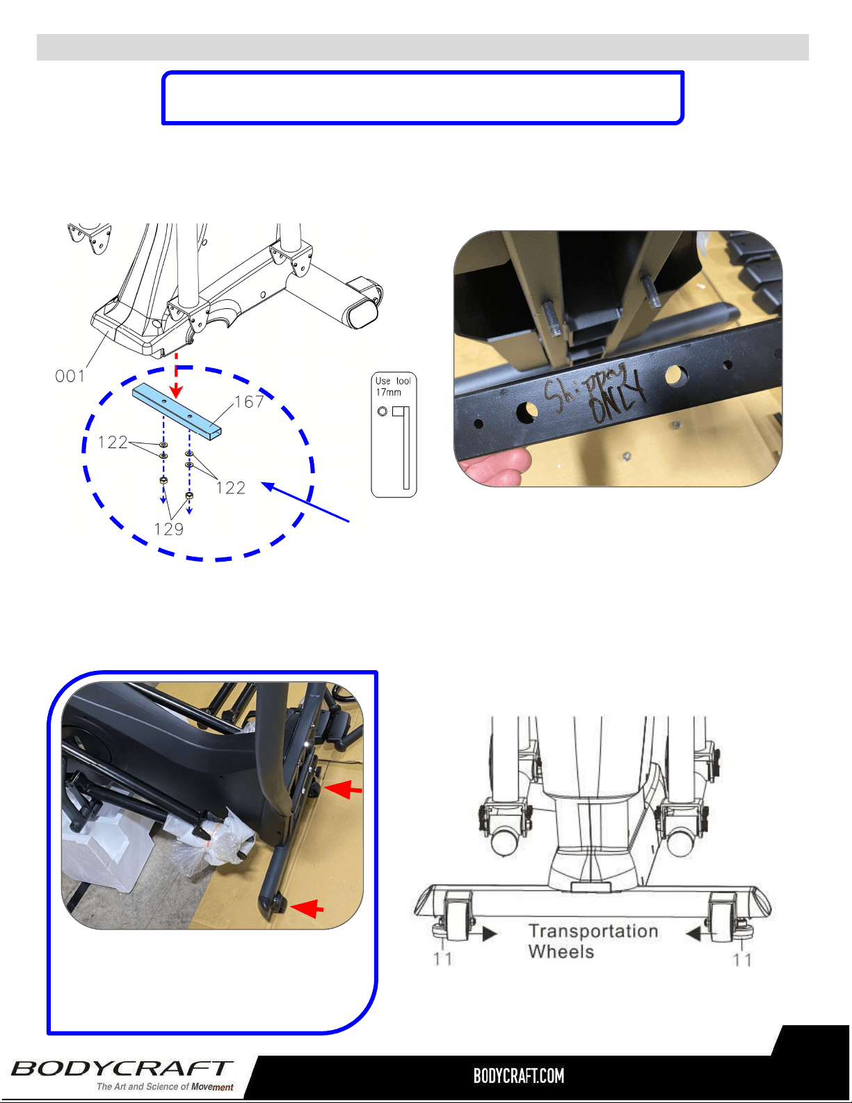
ProductAssembly
STEP1–RemovePackingTube
FollowtheleftdrawingtoremovethePackingTube(167)byunscrewing4pcsWashers(122)
and2pcsNuts(129).
STEP2–Leveler(11)&MainFrameAssembly
Followthebelowdrawingtoattach2pcsLevelers(11)undertheMainFrame’sFrontStabilizer
(transportationwheelsonthefront).Screwlevelersdowntoframewithnothreadsshowing.
NOTE:Thisstepcouldrequiretwopeople.
TIP: Easy to install the front
Levelers with Main Frame leaning
forward on packaging material
provided.
ManyImagesshownareGENERICforboththeE1200andE1000
EllipticalsonmostassemblySTEPS
12
NOTE:DONOTREUSETHISHARDWARE&PACKINGTUBE,
PLEASERECYCLE.
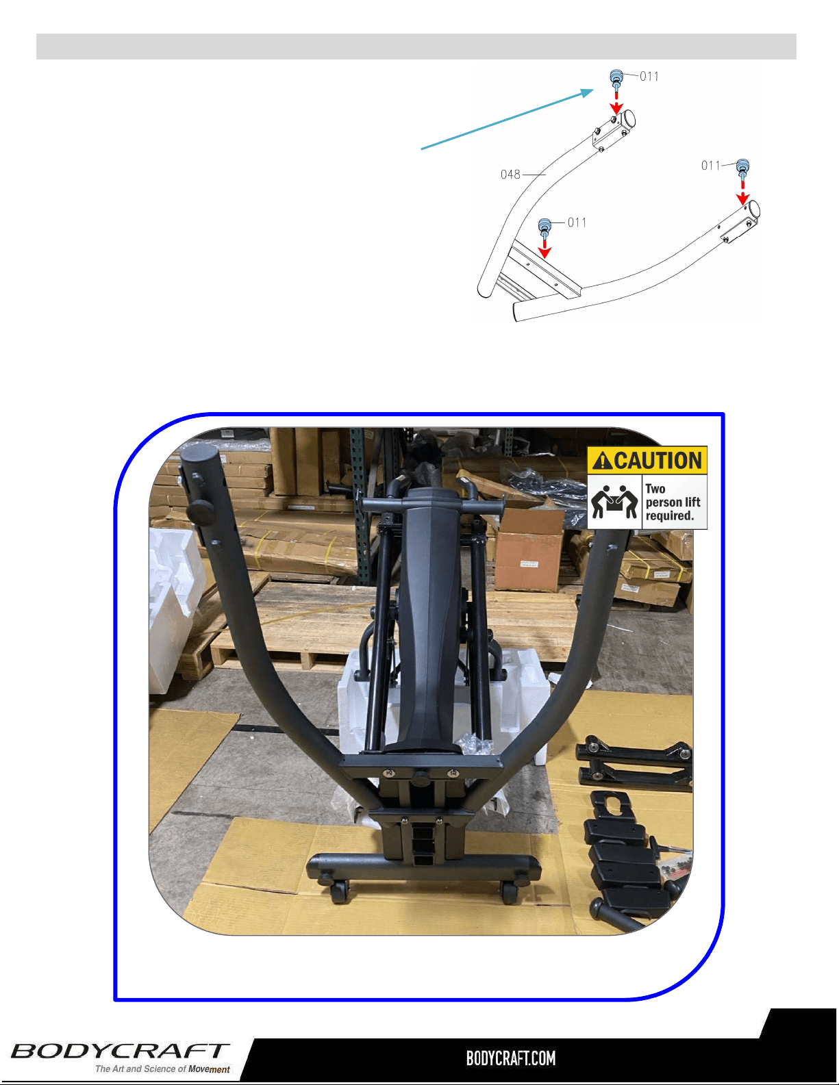
ProductAssembly
TIP: Easy to assemble Base Frame with Main Frame leaning
forward on packaging material provided. Shown assembled.
S
TEP4
–
OVERVIEWBaseFrame(48)Assembly
S
TEP3
–
Leveler(11)&BaseFrame(48)
Assembly
Followthedrawingontherighttoattach3pcs
Levelers(11)undertheBaseFrame(48).Screw
levelersdowntoframewithnothreadsshowing.
NOTE:Flipupsidedownandinstallthelevelers.
Thenflipoverwithlevelers(11)touchingtheground
fornextSTEP.
13
ProductAssembly
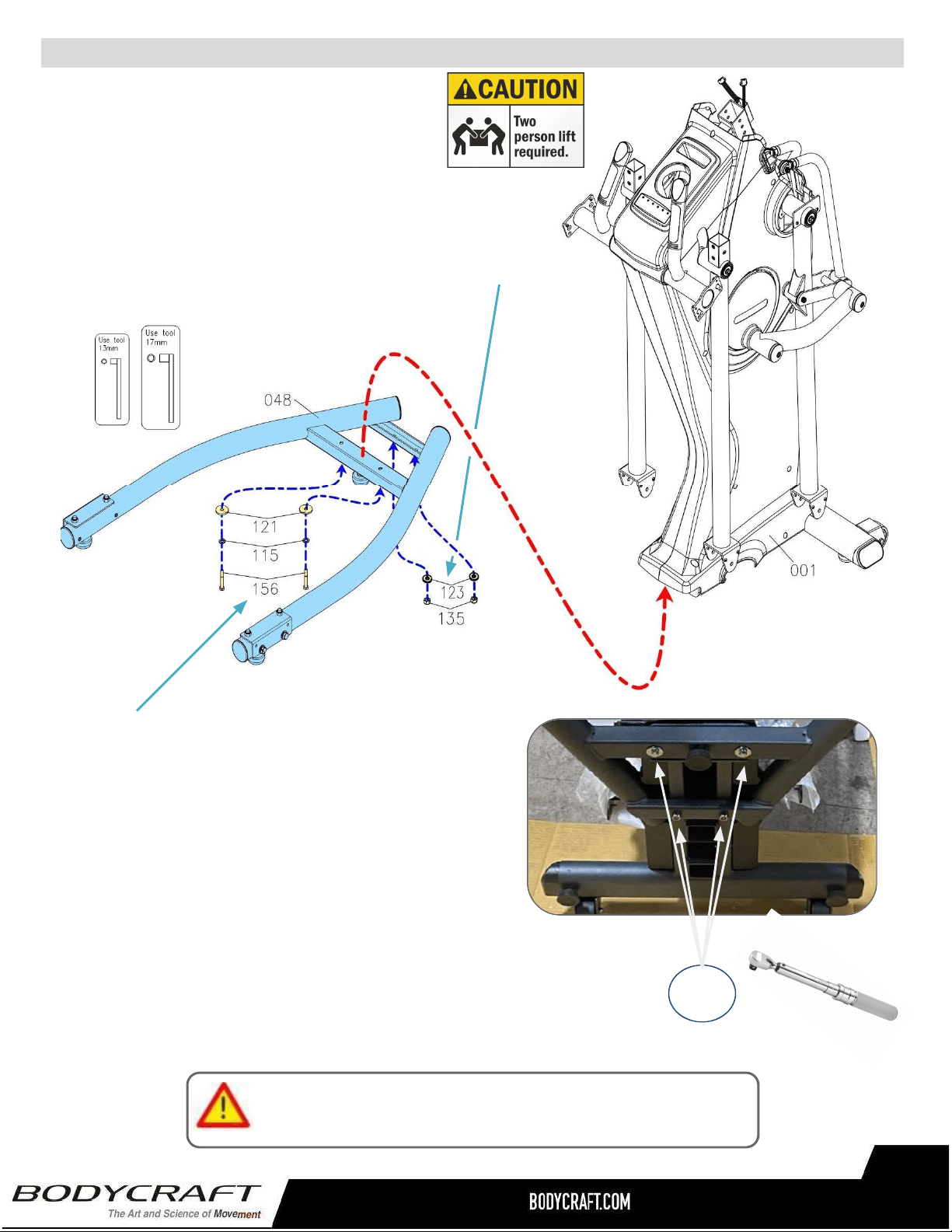
a. Followingthedrawingbelow,attachtheBaseFrame
(48)totheMainFrame(1)andslightlyattach2pcs
Washers(M10x23x2.0t)(123)and2pcsThinner
NylonNuts(M10xp1.5)(135).
S
TEP4
–
BaseFrame(48)Assembly
b.Thencontinuetoattachthe2pcsHexBolts
(M8xp1.25x55mm)(156),2pcsLock
Washers(M8)(115),2pcsWashers(M8x30x
2.0t)(121).
Pleaseconfirmallbolts/nutsaretightenedatthistime,
thencontinuetonextStep.
c.“TorqueTime”-TightentheHexBolts(156)and
ThinNylonNuts(135)totherecommended20ft-lbs+/-2lbs.
20ft-lbs
+/-2lbs
14
ProductAssembly
S
TEP5
–
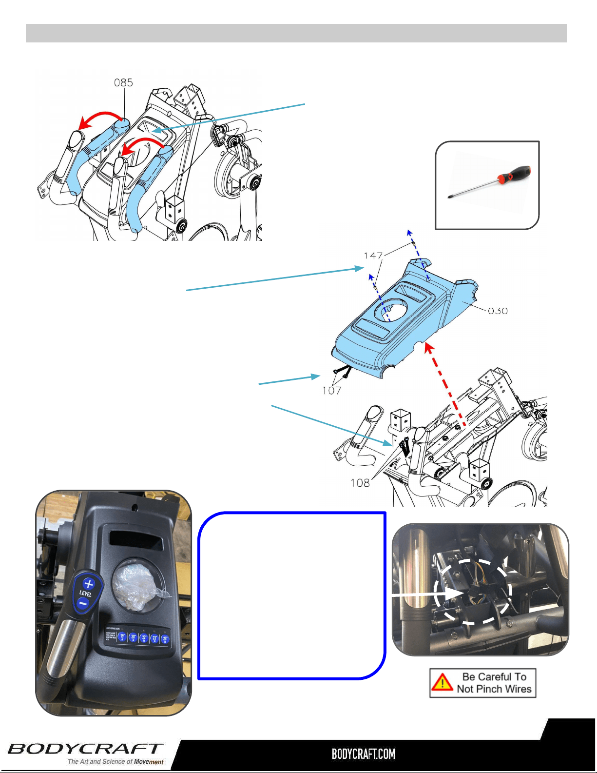
AdjusttheHandlebar&RemoveUpperCover(30)
b.ThenremovetheUpperCover(30)byfirst
removingScrews(147).
NOTE:Placethescrewsinasafeplacefor
laterinstallationduringSTEP11.
PHILLIPSSCREWDRIVERS#2
w/MagneticTIP
RecommendedTool:
TIP: When lifting the Upper
Cover (30), stop after 5” to
disconnect the two electrical
connections (107) (108). EASY
to damage cable & connectors
during installation.
* Not covered under warranty
if damaged during assembly.
15
c.SlowlyliftuptheUpperCover(30)about5”
andstop.DisconnectthetwoElectrical
Connectors(107)fromConnectors(108).
ThencompletelyremovetheUpperCover
(30)andplaceinasafeplaceforlater
installationduringSTEP11.
a.FirstRotatetheFixedHandlebar
(85)upwardasshown.
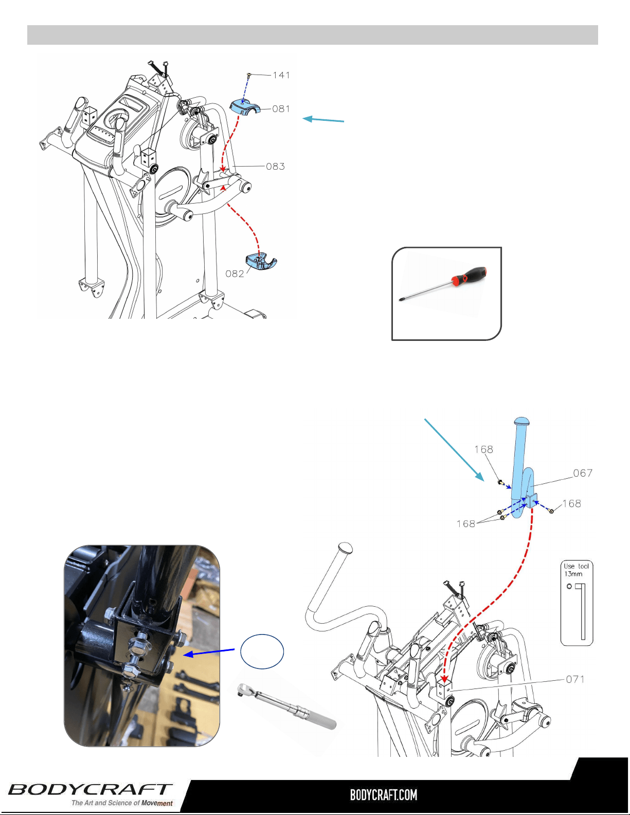
a. AttachtheRightUpperHandlebar(67)totheBackSwingArm(71)
andfullytightenwith4pcsHexFlangeBolts(M8xp1.25x16mm)
(168).
S
TEP7
–
UpperHandlebar(66,67)&RotatorCuff(63,64)Assembly
ProductAssembly
a.AttachtheUpper&Bottom
AdjustmentCovers(81,82)tothe
AdjustmentBracket(83)andfully
tightenwith1pcsPhillipsTrussScrew
(M4x20mm)(141).
b.RepeatSTEP6aforLeftside.
b.RepeatSTEP7aforLeftsidewithLeftUpperHandlebar(68).
S
TEP6
–
BaseFrame(48)Assembly
c.“TorqueTime”-TightentheHexBolts(156)totherecommended
….20ft-lbs+/-2lbs.
20ft-lbs
+/-2lbs
PHILLIPSSCREWDRIVERS#2
w/MagneticTIP
RecommendedTool:
16
ProductAssembly
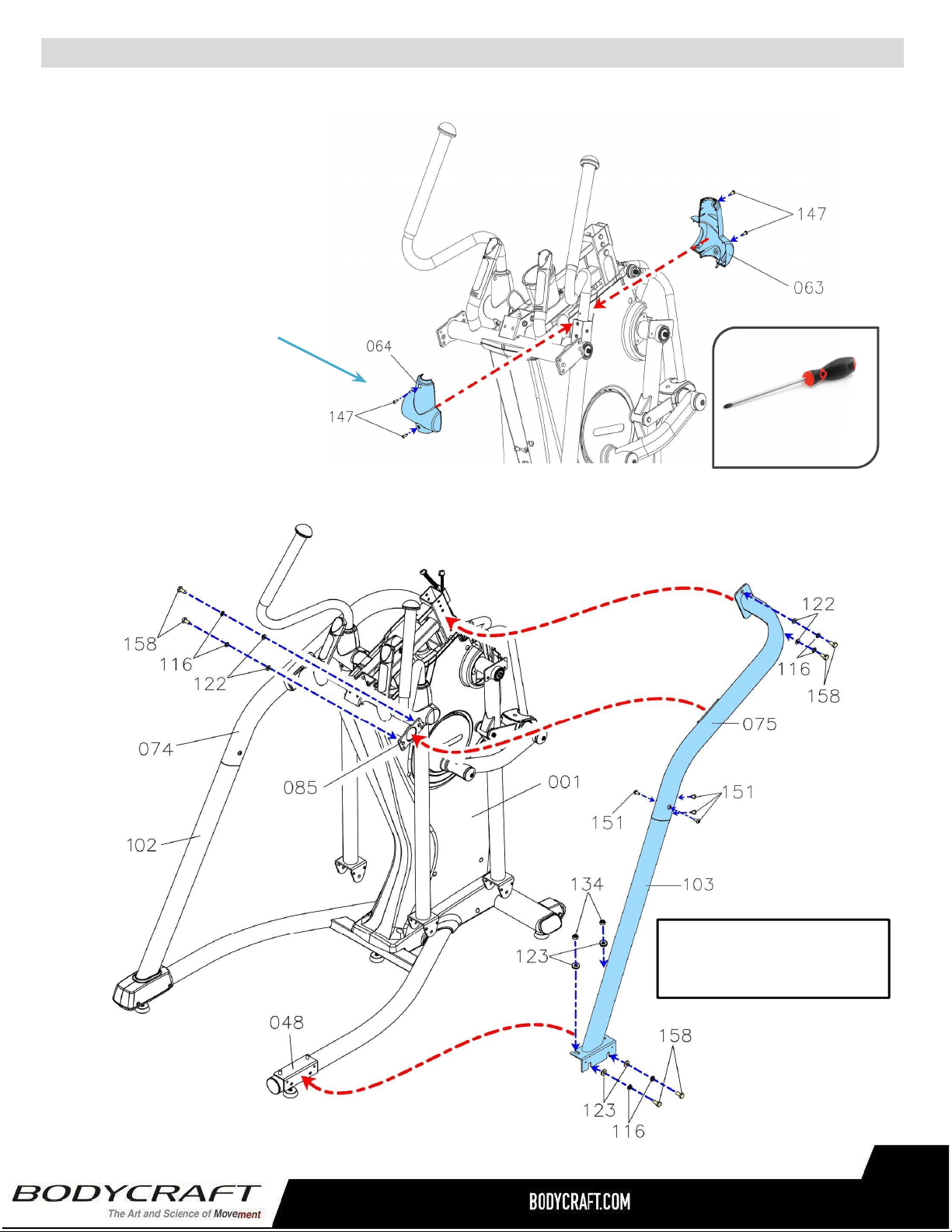
d.AttachtheFront
RotatorCuff(63)&Back
RotatorCuff(64)tothe
RightHandlebar(67)and
fullytightenwith4pcs
PhillipsPanScrews(M5
xp0.8x15mm)(147).
S
TEP7–(Continued)UpperHandlebar(66,67)&RotatorCuff(63,64)Assembly.
STEP8–OVERVIEWStationaryHandrail(74,75)&RearSupportTube(102,103)
Assembly
Overviewimagefor
STEP8athuSTEP8i
e.RepeatSTEP7dforLeft
....Side.
PHILLIPSSCREWDRIVERS#2
w/MagneticTIP
RecommendedTool:
17
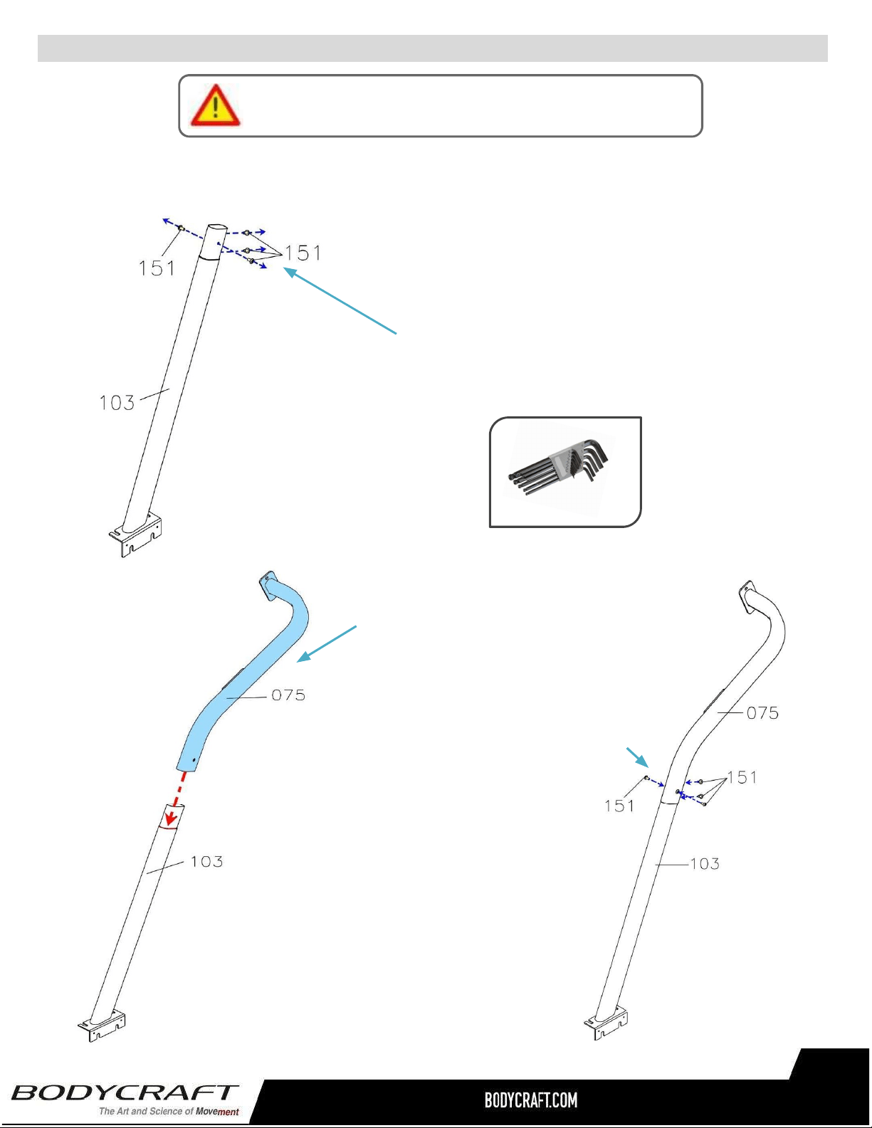
ProductAssembly
a..RemoveallPREASSEMBLEDhardwarefrom
RearSupportTube(103).
NOTE:Refertotheimageonleftwith4pcs
ButtonBolts(M8×p1.25×15mm)(151).Save
themforSTEP8c.
S
TEP8
–(
Continued)athruc.
b.AttachtheRightStationary
Handrail(75)totheRightRear
SupportTube(103).
c.Attachwith4pcsButtonBolts
(151).
PleaseHandTightenAllBoltsUntilSTEP9
18
AllenWrench5mm
RecommendedTool:
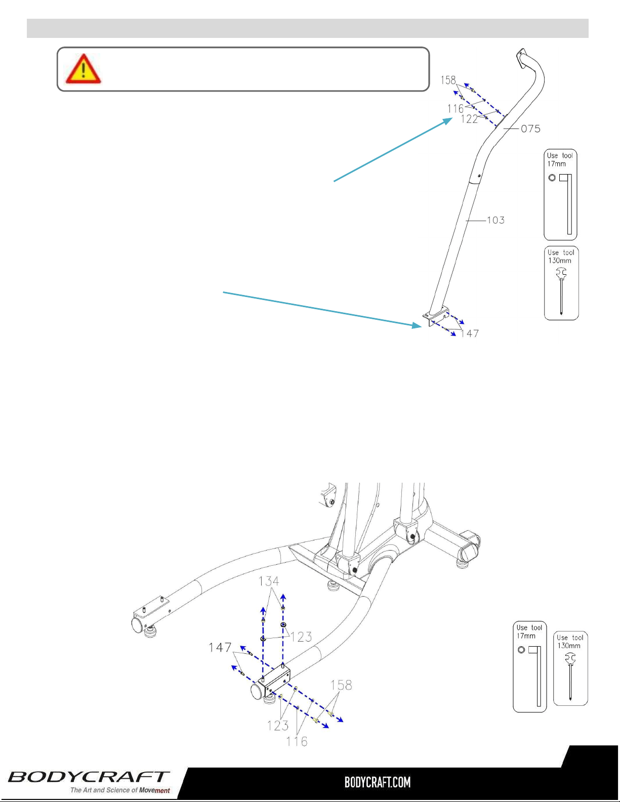
ProductAssembly
d.RemoveallPREASSEMBLEDhardwarefromStationary
Handrails(75&103).
NOTE:RefertotheimageonRightwith4pcsHexBolts(M10
×p1.5×20mm)(158),4pcsLockWashers(M10)(116),4pcs
Washers(10x19x1.5t)(122).SavethemforSTEP8f.
Alsoremovethe2pcsScrews(147).SavethemforSTEP11
wheninstallingtheplasticcovers.
e.RemoveallPREASSEMBLEDhardwarefromtheBaseFrame(48)
NOTE:RefertotheimageBelowwith2pcsNylonNuts(M10xp1.5)(134),4pcsWashers(10
x23x2.0t)(123),2pcsLockWashers(M10)(116),2pcsHexBolts(M10×p1.5×20mm)
(158),2pcsPhillipsPanScrews(M5xp0.8x15mm)(147).SavethemforSTEP8h.
S
TEP8
–(
Continued)dthrue.
PleaseHandTightenAllBoltsUntilSTEP9
19
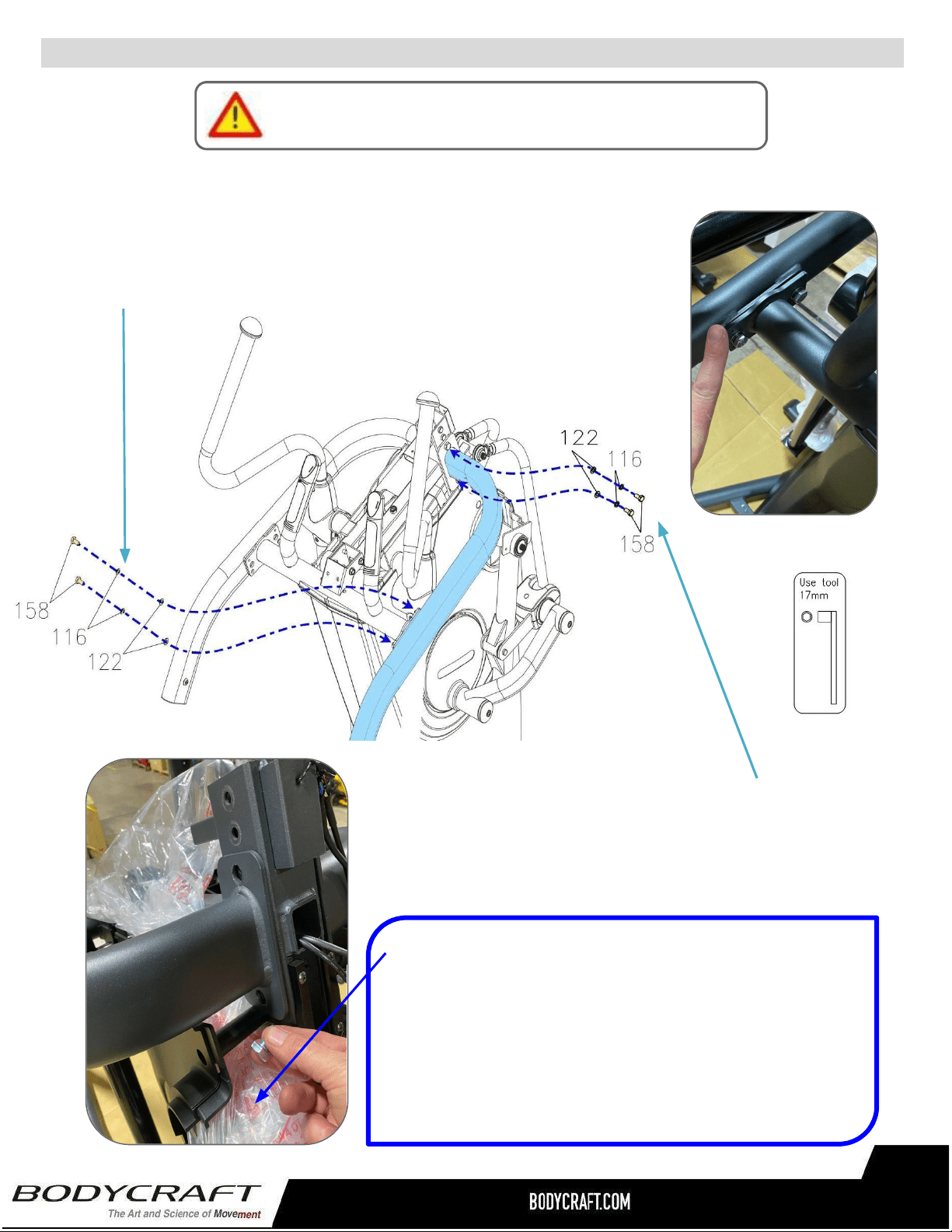
ProductAssembly
g.Continuetoattach2pcsHexBolts
(M10×p1.5×20mm)(158),2pcsLock
Washers(M10)(116),&2pcsWashers(M10
x19x1.5t)(122).
.
S
TEP8
–(
Continued)AssemblyofStationaryHandrail,fthrug.
PleaseHandTightenAllBoltsUntilSTEP9
f.AttachtheRightStationaryHandrail(75)totheMainFrame(1)
andslightlyattach2pcsHexBolts(M10×p1.5×20mm)(158),
2pcsLockWashers(M10)(116),&2pcsWashers(10x19x1.5t)
(122).
TIP–“Fill-the-Gap”
DuringSTEP8thruSTEP15hardwarecanbeeasily
droppedintothemainframe.Forextrainsurancetokeep
theassemblyprocessquickandlessstressful,placeextra
packagingbagsunderassemblyareastocatchhardwareif
accidentallydropped.
20
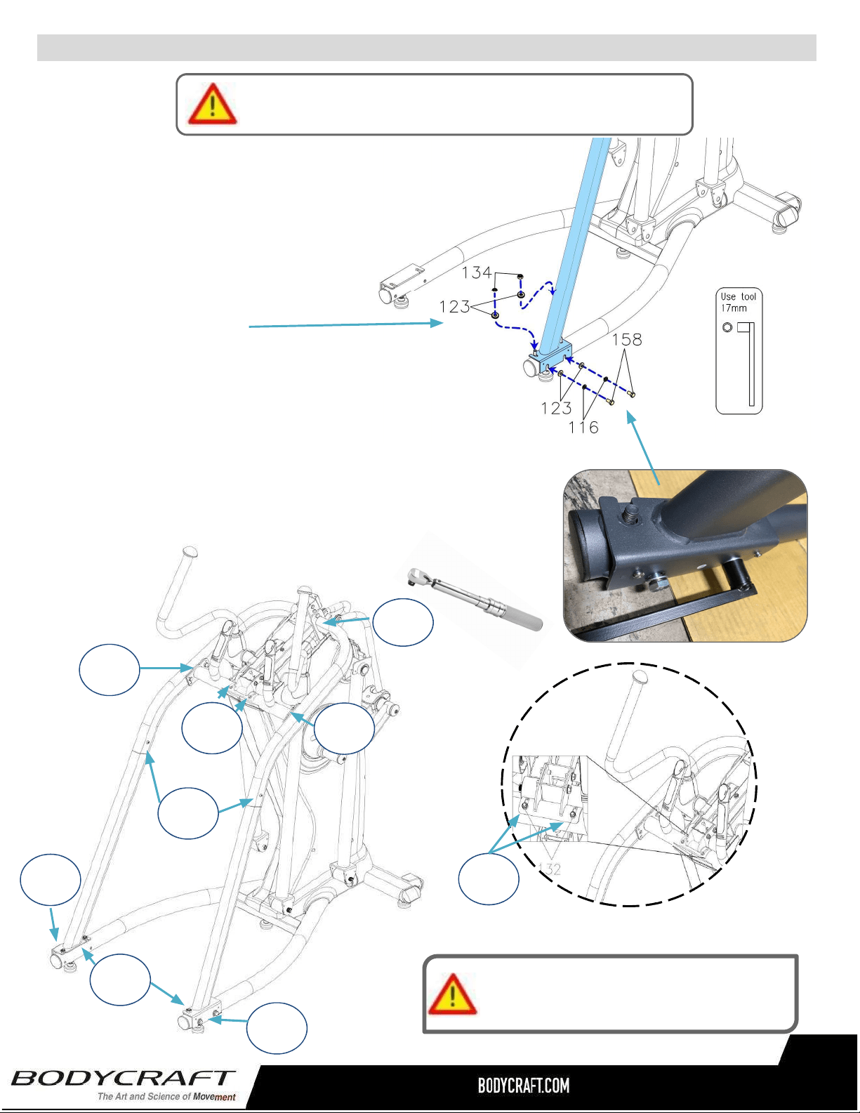
ProductAssembly
h.Thenslightlyattach2pcsNylonNuts
(M10xp1.5)(134),2pcsWashers(10x
23x2.0t)(123),2pcsLockWashers
(M10)(116),2pcsHexBolts(M10×
p1.5×20mm)(158).
i.RepeatSTEP8athru8htotheLeftside
usingtheLeftStationaryHandrail(74)&
LeftRearSupportTube(102).
S
TEP8
–
(Continued)hthrui.
PleaseHandTightenAllBoltsUntilSTEP9
TightenBolts&Nutsatthistime
totheRecommendedTorqueSpecs
25ft-lbs
+/-2lbs
25ft-lbs
+/-2lbs
25ft-lbs
+/-2lbs
10ft-lbs
+/-2lbs
15ft-lbs
+/-2lbs
25ft-lbs
+/-2lbs
25ft-lbs
+/-2lbs
25ft-lbs
+/-2lbs
15ft-lbs
+/-2lbs
STEP9–“TorqueTime”TightenallHexBolts,Nuts&
ButtonHeadScrewstotherecommendationsbelow.
21
ProductAssembly
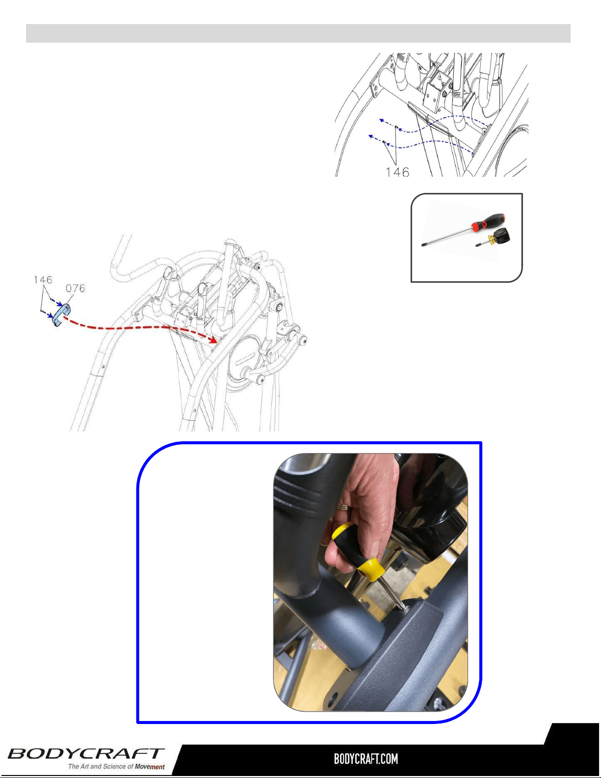
S
TEP10
–
SideHandrailCoverAssembly
c.AttachtheSideHandrailCover(76)to
theFixedHandlebar(85)andfullytighten
2pcsButtonScrews(146).
d.RepeatthesameprocessfortheLeftSide.
TIP:AShortPhillips
Screwdriverwithlarge
handleworksbestin
thetightspacesfor
theplastic
assemblies.
a. RemoveallPREASSEMBLEDhardwarefrom
theFixedHandlebar(85).
NOTE:RefertotheimageonRightwith2pcs
ButtonScrews(M5×p0.8×10mm)(146).
PHILLIPSSCREWDRIVERS#2
w/MagneticTIP
RecommendedTools:
22
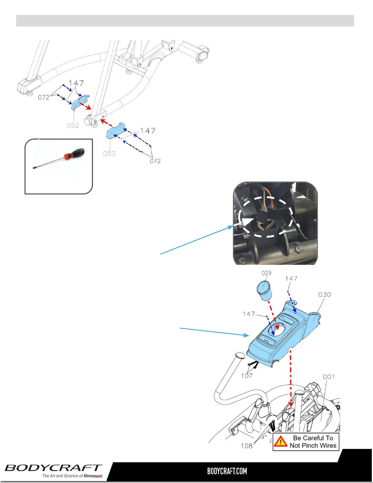
ProductAssembly
S
TEP11
–
RearEndCapCoverAssembly
a.AttachtheRightInner&
OuterRearEndCapCover
(52,53)andfully4pcsScrews
(147).
b.Thenpress4pcsScrewCaps
(72)ontotheRearSupport
Tube(103).
c.Repeattheabovesame
procedurefortheLeftSide.
a. LowertheUpperCover(30)totheMainFrame(1)
closeenoughtoattachthetwoElectrical
Connectors(107)toConnectors(108).
NOTE:Confirmthey(107)and(108)arefully
connectedandnotpinchedwhenloweringtheUpper
Cover(30)totheMainFrame(1).
b. ThencontinuetolowertheUpperCover(30)
totheMainFrame(1)andattachbyfullytighten
2pcsPhillipsPanHeadScrews(M5xp0.8x
15mm)(147).
c. FinallyinstalltheAccessoryTray(29)intothe
UpperCover(30).Justturnandlockinaclockwise
rotationtosecure.
STEP12–UpperCover
RecommendedTool:
PHILLIPSSCREWDRIVERS#2
w/MagneticTIP
23
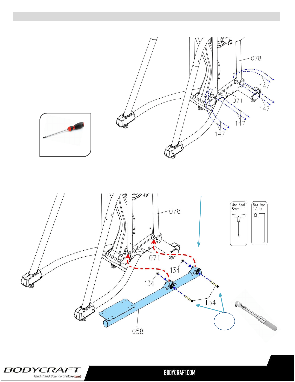
ProductAssembly
b.AttachthePedalArm(58)totheFront&BackSwingArm(78,71)andfullytighten2pcs
SocketBolts(M10xp1.5x90mm)(154)and2pcsNylonNuts(M10xp1.5)(134)
S
TEP13
–
PedalArm,PedalArmCoverAssembly
a. RemoveallPREASSEMBLED
hardwarefromtheFront&Back
SwingArms(71,78).
NOTE:RefertotheimageonRight
with8pcsPhillipsPanHeadScrews
(M5xp0.8x15mm)(147).
PHILLIPSSCREWDRIVERS#2
w/MagneticTIP
RecommendedTool:
c.“TorqueTime”-TightentheSocketBolts(154)totherecommended
….25ft-lbs+/-2lbs.
25ft-lbs
+/-2lbs
24
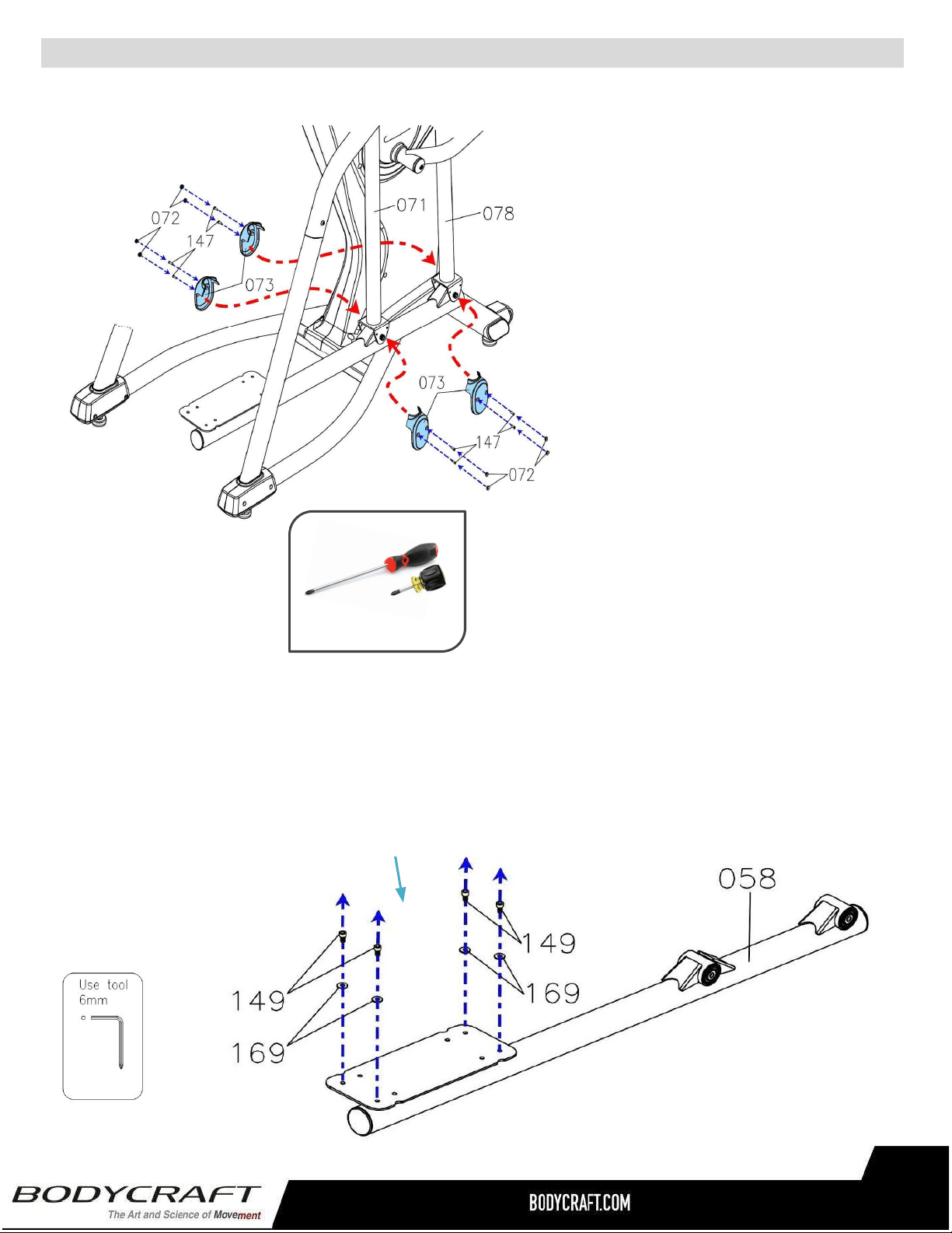
ProductAssembly
S
TEP13
–
(Continued)PedalArm,PedalArmCoverAssembly,cthrue.
c.Attachthe PedalArmCovers(73)
to the Front & Back Swing Arm
(78, 71) and fully tighten with 8pcs
Phillips Pan Head Screws (M5 x
p0.8x15mm)(147).
d.Thenpress8pcsScrewCaps(72)
ontothePedalArmCover(73).
S
TEP14
–
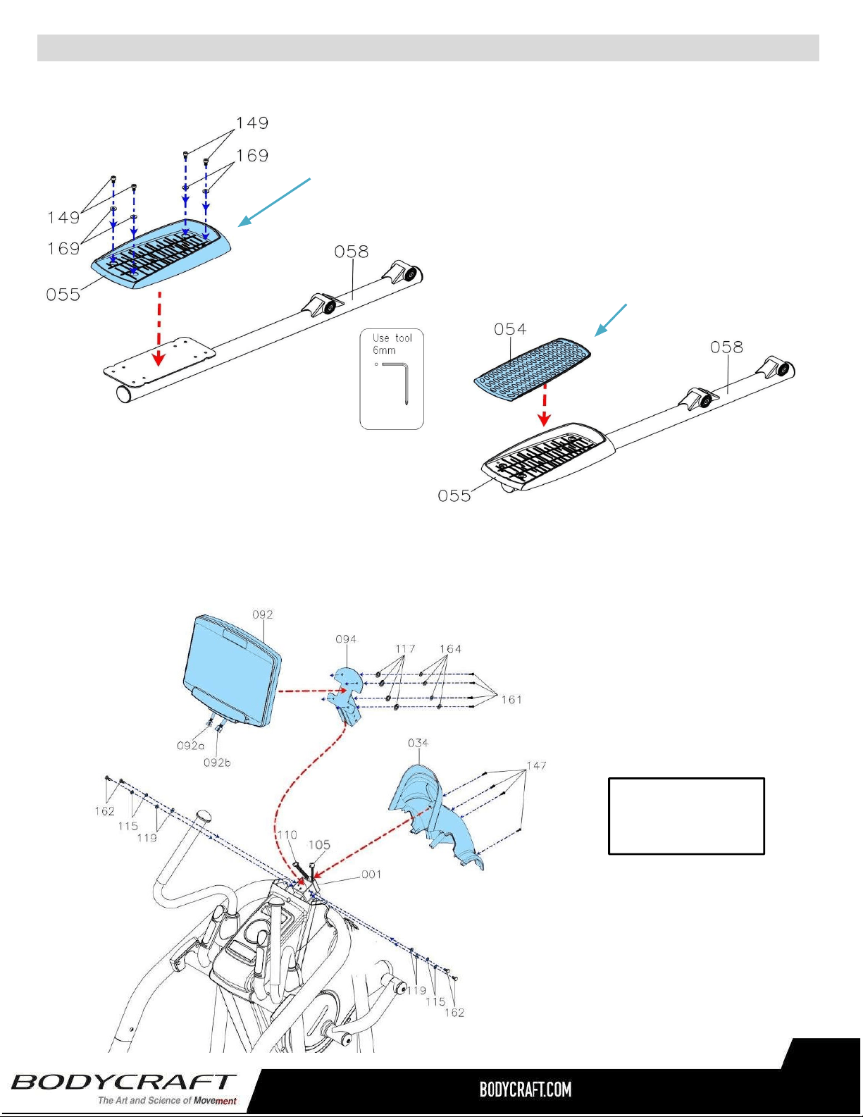
Pedal&Non-SlipPadAssembly
a. RemoveallPREASSEMBLEDhardwarefromthePedalArm(58).
NOTE:RefertotheimageonRightwith4pcsSocketBolts(M8×
p1.25×15mm)(149)and4pcsWashers(8×19×2.0t)(169)
PHILLIPSSCREWDRIVERS#2
w/MagneticTIP
RecommendedTools:
e. Repeat the same process from
STEP 13a thru 13d for the Left
Side.
25
ProductAssembly
STEP14–(Continued)Pedal&Non-SlipPadAssembly,cthrue.
Overviewimage
forSTEP15
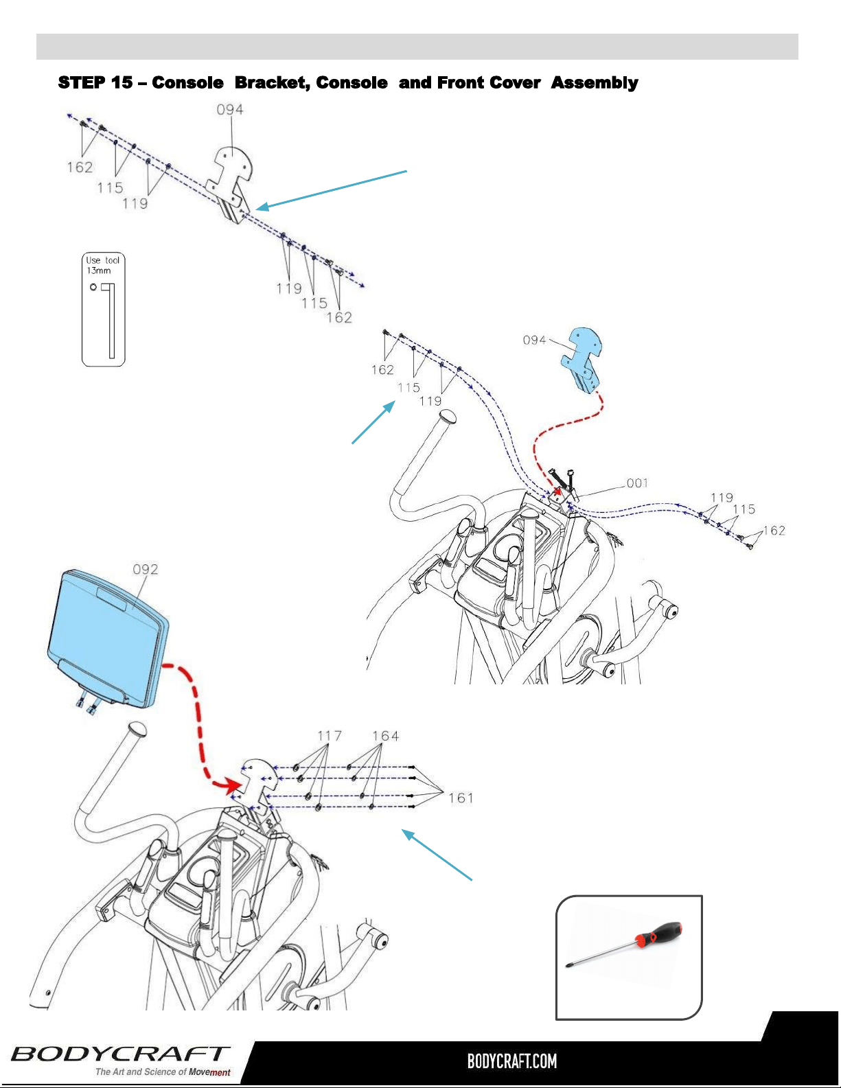
STEP15OVERVIEW–ConsoleBracket,ConsoleandFrontCoverAssembly
d.ThenPlacetheNon-SlipPad(54)ontothe
Right Pedal (55). Confirm all four inserts
arefullydepressedflatintopedalholes.
c. Repeat the same process from STEP
14athru14dfortheLeftSide.
c.Attach the Right Pedal (55) to theRight PedalArm(58)and
fullytightenwith4pcsBolts(149)and4pcsWashers(169).
26
ProductAssembly
b.AttachtheConsoleBracket(94)to
theMainFrame(1)andfullytighten
with4pcsWashers(119),4pcsLock
Washers(115)and4pcsHexBolts
(M8×p1.25×15mm)(162).
a. RemoveallPREASSEMBLEDhardwarefromthe
ConsoleBracket(94).
NOTE:Refertoimageonleftwith4pcsWashers
(8×16×2.0t)(119),4pcsLockWashers(M8)(115)
and4pcsHexBolts(M8×p1.25×15mm)(162).
c.AttachtheConsole(92)tothe
ConsoleBracket(94)andfullytighten
with4pcsScrews,PhilipsPanHead
(M6xp1.0x15mm)(161),4pcs
Washers(6x13x1.0t)(117),and
4pcsLockWashers(M6)(164).
27
PHILLIPSSCREWDRIVERS#2
w/MagneticTIP
RecommendedTool:
ProductAssembly
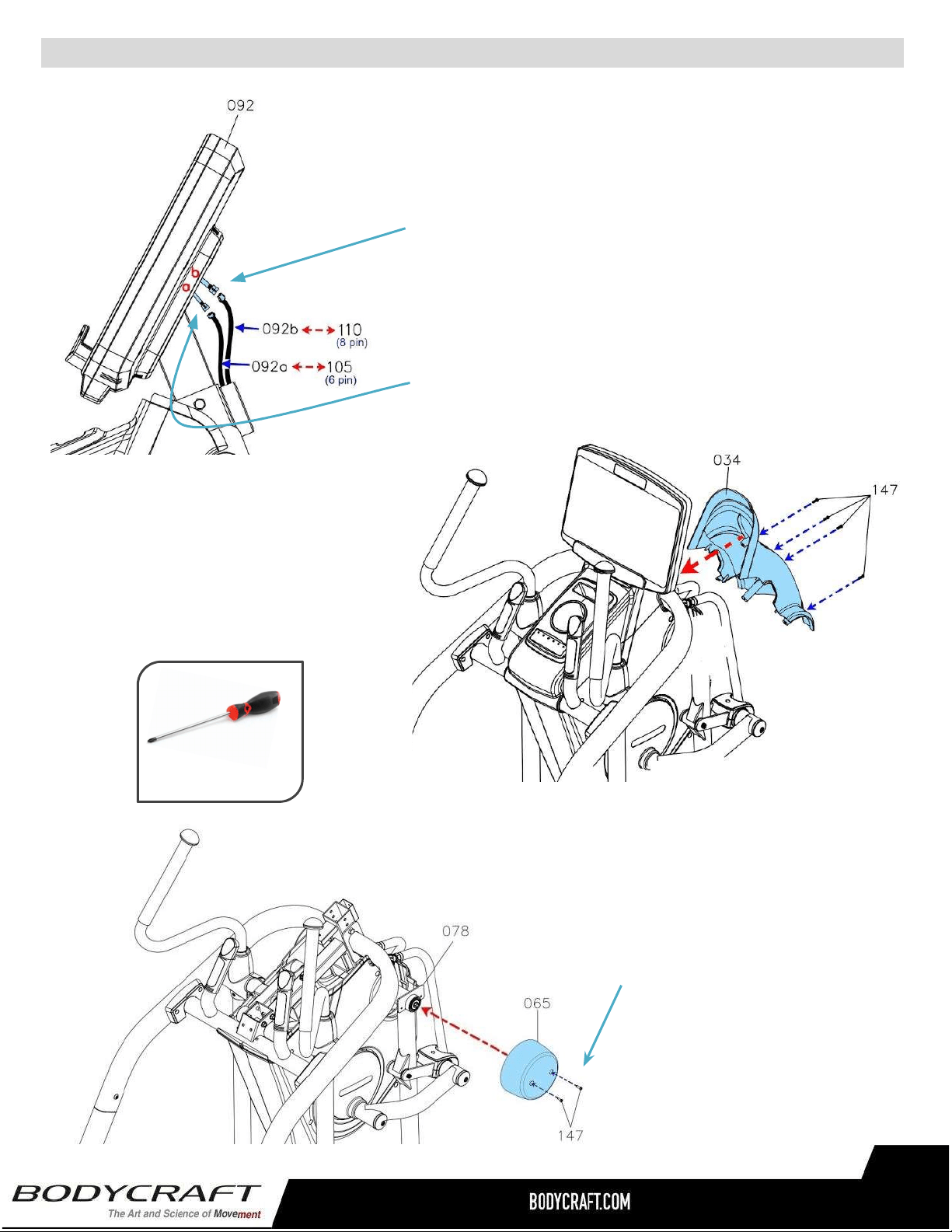
f.AttachtheFrontCover(34)tothe
MainFrame(1)andfullytighten
with4pcsScrews,PhilipsPan
Head(M5xp0.8x15mm)(147).
STEP15–(Continued)ConsoleBracket,Consoleand
FrontCoverAssembly.
STEP16–FrontSwingArmCoverAssembly
a. AttachtheUpperCover
(30)totheMainFrame(1)
andfullytighten2pcs
PhillipsPanHeadScrews
(M5xp0.8x15mm)(147).
d.ConnecttheConsolePulseSensor
Wire(92b)totheFirstPulseSensor
Wire(110).
e.AttachtheConnecttheConsole
ConnectionWire(92a)totheFirst
ConnectionWire(105).
PHILLIPSSCREWDRIVERS#2
w/MagneticTIP
RecommendedTool:
b.Repeatthe same processfor
theLeftSide.
28
29
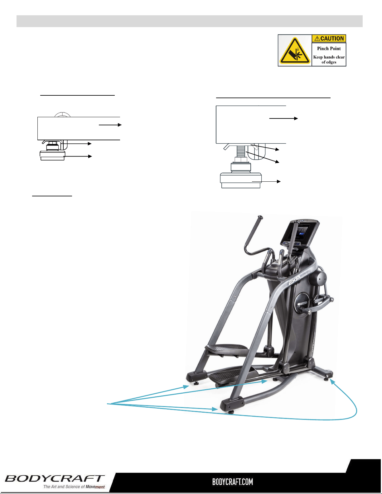
LEVELING:
Afterplacingitintheintendedlocationfor
use,checkthestabilityoftheElliptical.Ifit
isnotlevel,reviewingthefollowing
directions:
● Firststartonthesidetoside
movementonthefrontLevelers(19),
thentherearLevelers(19).
● Followuponfronttobackmovement
onrearLevelers(19).
● FinallysecurecenterLeveler(19)
beingfirmtoground.
● TightentheAdjustmentPlatesecurely
againsttheStabilizertolockthe
Leveler(19)instableposition.
Adjusteddownawayfromframe
Stabilizer
AdjustmentPlate
Leveler(19)
Adjusteduptoframe
S
TEP17“TheLastSTEP”
–
Leveler&StabilizerAssembly
a. BesuretotightentheLevelers(19)securelyagainstthe
Stabilizers(2,3)untilscrewlinesareeliminatedasshownwith
drawing#1.
NOTE:
● Forthefinalstep,makesurealltheboltsandnutsarefullytightenedbeforeusingtheitem.
● Checkwhetherthelevelersareevenonthefloor.Ifthelevelersarenotevenitwillproduce
(noise).Iftheyarenotlevel,reviewtheSTEP17again.
ProductAssembly
Stabilizer
AdjustmentPlate
Screwline
Leveler(19)
Drawing #1 - Closer to Ground
Drawing #2 - Away from Ground
29
Totalof5Levelers.
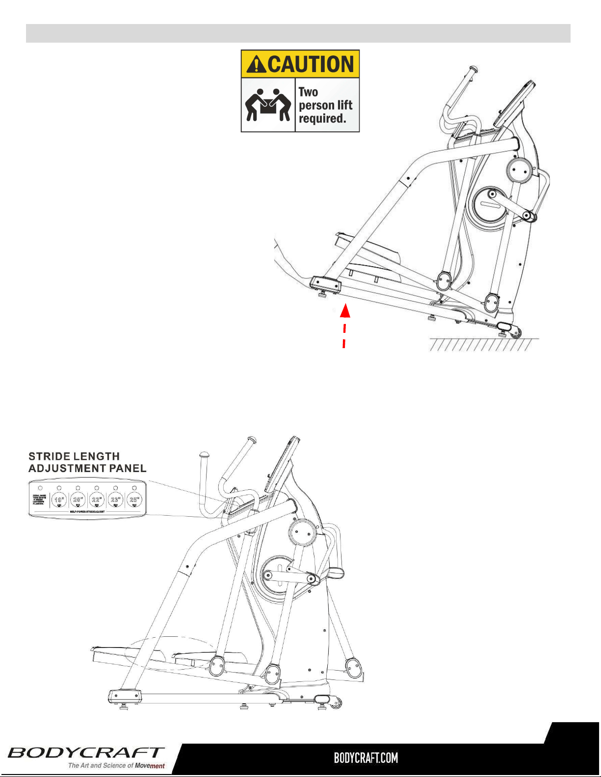
OperationalInstruction
TheE1200Ellipticalhasincluded
5auto-adjustablestrides.
PresstheSTRIDELENGTH
ADJUSTMENTPANELfrom
19’’/480mm,20’’/510mm,
22’’/560mm,23’’/590mm,
25’’/640mmandchoosethestride
lengththatsuitsyouthemost.
30
H
OWTOADJUSTTHESTRIDELENGTH
HoldtheBaseFrame(48)upwithtwo
handsandmovetheitemtothedesired
locationthencarefullybringtofloor.
NOTE:Makesuretorelevelif
unstableaftermovedtonewlocation,
seeSTEP17.
H
OWTOMOVETHEE1200ELLIPTICAL
SAFELY
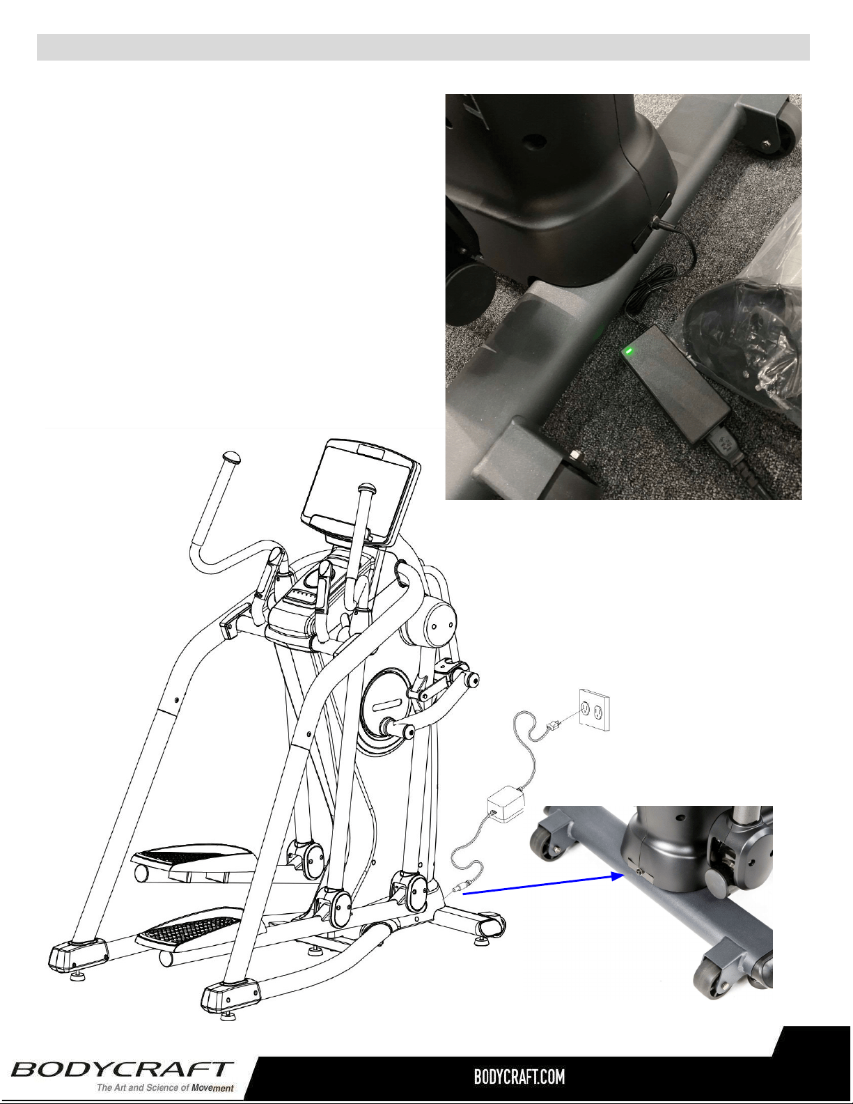
Plugging in the E1200 (E120) Elliptical -
Adaptor Usage
a. Connect the Adaptor (12DC / 5A) (172) &
Power Cord (173) to the connector located on
the front of the Main Frame (1).
b. Plug the Adaptor (12DC / 5A) (172) & Power
Cord (173) into an 120 vac/15 amp electrical
wall outlet to light up the console.
NOTE: Long-Term Storage: When the item is not in
use for any length of time, ensure that the power
adapter is unplugged from the electrical outlet for
safety..
OperationalInstruction&CleaningProductRecommendations
31
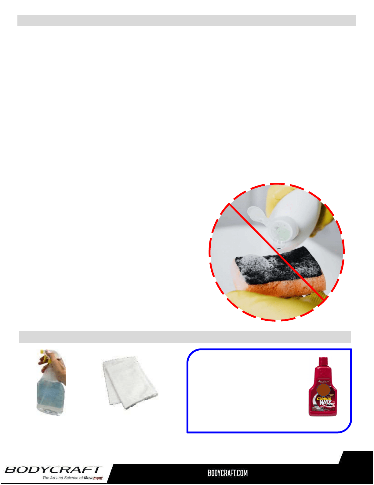
CAUTION:Donotuseanyacidiccleaners.Doingsowilldiscolortheplastics,painted
surfacesandpowdercoatings.Neverpourwaterorsprayliquidsonanypartoftheitem.
1. UnplugEllipticalbeforeusinganycleaningproduct.
2. Recommendthatyoucleantheitembeforeandaftereachexercisesession.Toremovedust
anddirtfromtheitem,wipeallexposedsurfacedwithslightlydampsoftclothonly,neveruse
solvents.
3. Cleanwithmildsoapandwatercleanersonly.
4. Alwayskeepconsoleandelectricalpartscleananddry.
5. Wipeorvacuumanydustorotherobjectthatmayhaveaccumulatedunderneaththeitem.
6. Makesurethecleaningsolutionsorbottlesarealwayslevelonthefloor.Removeanyliquid
rightawaythatmaydriporaccidentallytipoveronthefloor.
7. Onlyapplywitharagandwipetilldrywithcleancottoncloth.
CleaningyourElliptical
32
TIP ON FRAME ONLY: For extra
protection from fingerprints,
sweat stains or just plain dirt,
apply an automotive grade
cleaner wax if desired. Also
makes future cleaning easier.
ThefollowingisRECOMMENDEDforcleaningsupplies:
100%COTTON
CLEANINGCLOTHS
(Do Not Use on any Plastic or Console Glass)
MILDCLEANING
SOLUTION
● DO NOT USE ABRASIVE CLEANING
SCRUBBING PADS.
● DO NOT USE AMMONIA CLEANERS.
● DO NOT USE CITRIC CLEANERS

PulseHandGrips
Thisproductcomesstandardwithstainlesssteelpulsehandgrips.Toactivate,gentlygraspbothhand
gripstoobtainaheartratereading.(Note:ItisrecommendedtowearacheststrapforHeartRatecontrol
program,asitismoreaccurate.Ifyouwearacheststrapandusehandgripsatthesametimeforheart
ratemonitoringpurpose,pleasenotetheconsolewilltakethemeasurementofthecheststrap.)Forsafety,
itisnotrecommendedtousetheHeartRateSensorswhenexercisingathighspeeds.TheSensorsmay
notalwaysbeaccurateforanyuseratallspeeds.Individualphysiologyisafactorthatcandetermine
accuracy,oreveniftheSensorsworkforyouatall.TheTouchHeartRatereadingisnotintendedtobe
usedformedicalpurposes.
PulseGripOperatingTips:Ifyouarenotgettingaconsistentreadingwhileusingthehandpulseoption,
werecommendthefollowingsuggestions:
● Makesurethatthepalmsofthehandsaretouchingthecontactarea
ofeachhandpulsegrip.
● Maintainanevenpressureonthegrips.
● Donotholdthehandpulsegripstootightly.
● Makesureyourpalmsarewarmandslightlymoist.
● Excessive movement especially on an elliptical handrail is not
optimum for hand grips or any High Intensive Exercise while on a
machine.
BuiltinWirelessHeartRateReceiver
Note:Cheststraptransmitterdoesnotcomewiththisunit;contactBODYCRAFT,
oryourdealerforpurchase.
Thisproductisequippedwithabuilt-inreceiverforyourheartratemonitoring.Anyheartratetelemetrystrap
thattransmitsat5KHzorBluetoothiscompatible.Togetanaccuratereadingusingthesedevices,youwill
need to be within three feet of the console, and a minimum of four feet from others using a heart rate
monitoringdevice.
Note:Thetransmittermayfluctuateerraticallyifyouaretooclosetootherheartratemonitoringequipment
orthereisotherelectronicsnearby,suchasTV,Radio…
While usingheartrate controlmodes, thecomputer monitorstheexactmeasurementofyour pulse. Heart
rate frequency is displayed while the computer continually compares heart rate to the preprogrammed
personaldata.Thecomputeradjuststhewattagetomaintainheartrateatthepreprogrammedlevel.
HowtoWearYourSensor/Transmitter(ChestStrap)
○ Buckleoneendofthecheststrapontothetransmitter.
○ Adjustthebandlengthsothatthefitissnug,butnottootight.
○ Buckletheotherendofthecheststrapontothetransmitter.
○ Centerthetransmitteronyourchestbelowthepectoralmuscle(breasts).
○ Stretchthetransmitterawayfromyourchestandmoistentheconductive
electrodestripslocatednexttothebuckleswithwater.
Note:Thetransmitterisonautomaticallywhenbeingworn.Itisoffwhenitisnotconnectedtoyourbody.
However,asmoisturemayactivatethetransmitter,thoroughlydrythetransmittertoprolongbatterylife.
HeartRateMonitoringDevice&ExerciseTips
33

ErraticHeartRateReadings:
Erratic readings on the receiver can be caused by electromagnetic disturbances. If the heart rate
readings appear to be abnormal, check that your product is not within range of other strong
electromagneticsignals.Commonsourcesaretelevisions,computers,cars,cellphones,TVantennas
andhighvoltagepowerlines(bothaboveandbelowground).Pleasenote:Staticelectricityinclothing
ora flapping shirt can cause electricalinterference, so someitems of clothing,i.e. man-made fibers,
canalsobethecause.Pleasetrywettingthet-shirtintheareawherethetransmitteris.
Ifthebatteryofthetransmitterisrunninglow,thetransmissionrangedecreasesandmaycauseerrors
similartotheoneslistedaboveinthisdocument.
Heartrateisanimportantkeytoyourexercise
Medicalresearchhasshownusthatthere isan amountofexercise, whichisenoughto conditionthe
cardiorespiratorysystem andthe musclesof thebody. This amount of exercise is between 60%and
85% of your maximum heart rate measured during a training session. This range allows enough
exercisetoachievefitness,butnotanexcessiveamounttocauseinjury.Yourheartrateisanexcellent
indicatoroftheamountofstressplacedonthecardiovascularsystem.
Ifexerciseintensityistoolowortoohigh,nogainswillbemadeinfitness.Iftheintensityistoolow,the
stresslevelsareineffective.Iftheintensityistoohigh,injuryorfatiguemaysetyourexerciseprogram
back as you try to recover. Your target heart rate, the intensity needed to improve cardiovascular
fitness,dependsprimarilyonyourageandnotyourstateoffitness.Itiscalculatedasapercentageof
yourmaximumheartrate,estimatedas220minusyourage.Itismosteffectivetotrainatyourtarget
heartratebetween60%and85%ofyourmaximumheartrate.
Getasmartstartonexercising.
Anyone over the age of 35, as well as younger persons whom are overweight, should check with
his/her physician before beginning any type of exercise program. People who have diabetes or high
blood pressure, a family history of heart disease, high cholesterol or have lead a sedentary lifestyle
shouldprotect themselves with a medical check-up and a stress test, preferably administered during
exercisebyahealthcareprofessional.
● Alwaysstretchbeforeyourworkouttoloosenmuscles,andafterwardstocooldown.
● Thefirstfewminutesofyourworkoutshouldbedevotedtowarmingupmusclesbeforea
vigorousworkoutandbuildingyourheartrateslowly.
● Afteryouraerobicworkoutofabout24-32minutes,spend10minutesgraduallyreducingyour
heartratewithalowerresistancelevel.
Remember,tostartslow,withintensitylow,untilyoubuildenduranceandstrength.Andalwaysconsult
yourphysicianbeforebeginninganyexerciseprogram.
HeartRateMonitoringDevice&ExerciseTips
34

35

HeartRateMonitoringDevice&ExerciseTips
36
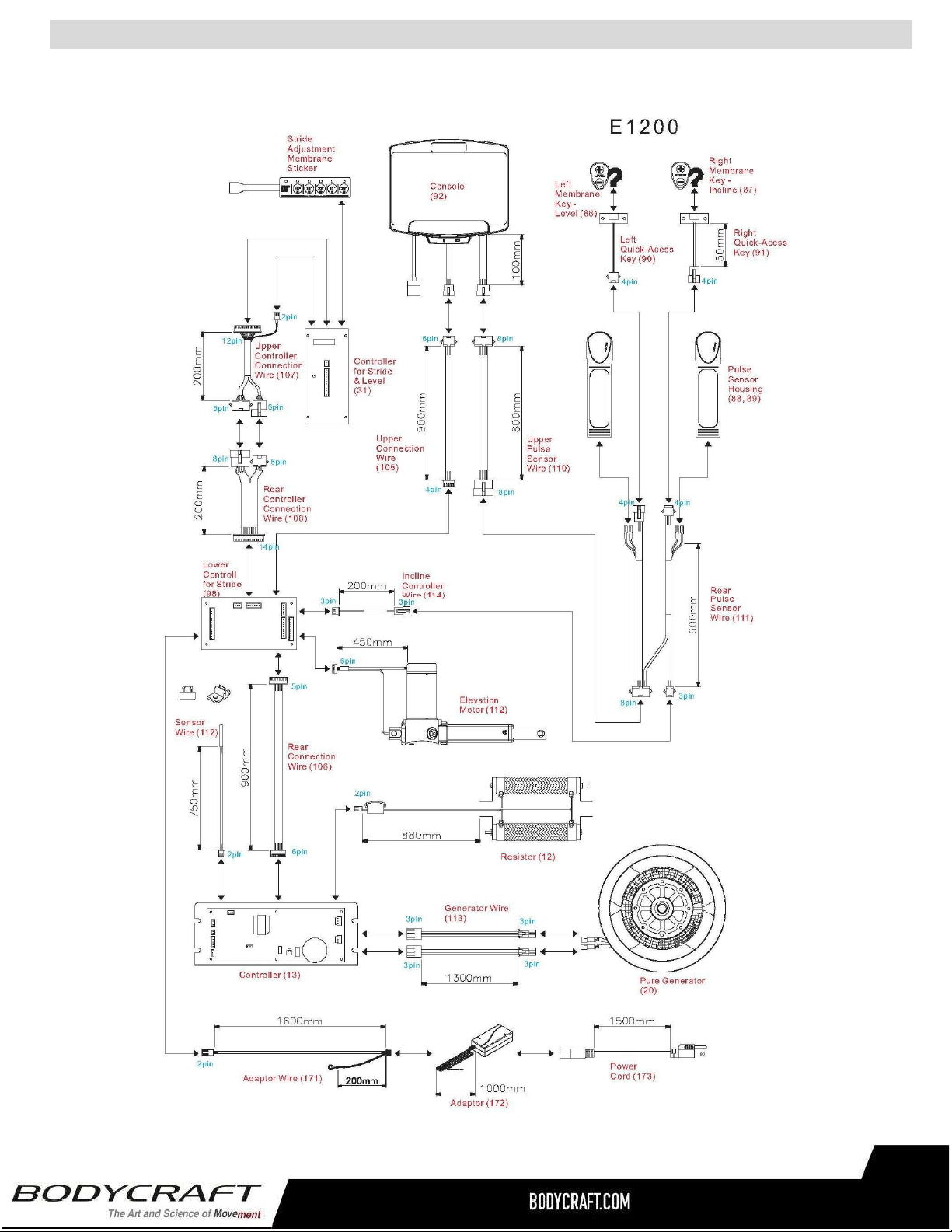
CircuitDiagram
37

PartLists-Detailed
Part# Description Qty
E120-001 MainFrame 1
E120-002 Crank 2
E120-003 Bearing(6004) 12
E120-004 Spacer(25.1x32x40mm) 1
E120-005 Magnet 1
E120-006 Pulley(235) 1
E120-007 CrankAxle 1
E120-008 Sleeve 4
E120-009 SensorWireStand 1
E120-010 EndCap 2
E120-011 Leveler 5
E120-012 Resistor 1
E120-013 Controller 1
E120-014 WheelAxle 2
E120-015 TransportationWheel 2
E120-016 DecorationBracket 1
E120-017 ElevationMotor 1
E120-018 EyeBolt(40mm) 2
E120-019 TensionBracket 4
E120-020 Generator 1
E120-021 EyeBolt(67mm) 2
E120-022 AdjustmentTubeFixedPlate 2
E120-023 Bearing(6000) 2
E120-024 Belt(762J8) 1
E120-025 Pulley(120-42) 1
E120-026 Belt(1428J8) 1
E120-027 Spacer(10x14x32mm) 1
E120-028 CrankCover 2
E120-029 AccessoryTray 1
E120-030 UpperCover 1
E120-031 ControllerforStride&Level 1
E120-032 LeftCover 1
E120-033 RightCover 1
E120-034 FrontCover 1
E120-035 WheelBearingAdapter 12
E120-036 Bearing(6201) 12
E120-037 InnerCrankLinkage 2
E120-038 WheelBearingSpacer(8x14x18mm) 2
E120-039 Bearing(6905) 20
E120-040 SwingLinkage 2
E120-041 SwingLinkageCover 2
E120-042 LeftStrideLinkage 1
E120-043 RightStrideLinkage 1
Part# Description Qty
E120-044 WheelBearingSpacer(8x14x36mm) 4
E120-045 RodEndPlainBearing 2
E120-046 StrideAdjustmentTube 1
E120-047 RoundPlug(60mm)forMainFrame 4
E120-048 BaseFrame 1
E120-049 Bearing(6005) 2
E120-050 LeftRearEndCapCover-Outer 1
E120-051 LeftRearEndCapCover-Inner 1
E120-052 RightRearEndCapCover-Inner 1
E120-053 RightRearEndCapCover-Outer 1
E120-054 Non-SlipPad 2
E120-055 Pedal 2
E120-056 RoundPlug(60mm)forPedalArm 4
E120-057 LeftPedalArm 1
E120-058 RightPedalArm 1
E120-059 SquarePlug(20x40) 4
E120-060 WheelBearingAdapterforStrideTube 4
E120-061 Bearing(6002) 2
E120-062 WheelBearingSpacer(10x25x47mm) 4
E120-063 FrontRotatorCuff 2
E120-064 BackRotatorCuff 2
E120-065 FrontSwingArmCover 2
E120-066 LeftUpperHandlebar 1
E120-067 RightUpperHandlebar 1
E120-068 FoamGripforUpperHandlebar 2
E120-069 RoundPlug(31.8mm) 2
E120-070 TubeCap 4
E120-071 BackSwingArm 2
E120-072 ScrewCap 24
E120-073 PedalArmCover 8
E120-074 LeftStationaryHandrail 1
E120-075 RightStationaryHandrail 1
E120-076 SideHandrailCover 2
E120-077 LeftFrontSwingArm 1
E120-078 RightFrontSwingArm 1
E120-079 PedalWheelBearingAdapter 8
E120-080 OuterCrankLinkage 2
E120-081 UpperAdjustmentCover 2
E120-082 BottomAdjustmentCover 2
E120-083 AdjustmentBracket 2
E120-084 FoamGripforFixedHandlebar 2
E120-085 FixedHandlebar 1
38

PartLists-Detailed
Part# Description Qty
E120-086 LeftMembraneKey-Level 1
E120-087 RightMembraneKey-Incline 1
E120-088 PulseSensorTopHousing 2
E120-089 PulseSensorBottomHousing 2
E120-090 LeftQuick-AccessKey 1
E120-091 RightQuick-AccessKey 1
E120-092 Console 1
E120-094 ConsoleBracket 1
E120-095 LockBracket 1
E120-096 WheelBearingSpacer(10x17x22mm) 1
E120-097 InclineMotorAxle 1
E120-098 LowerControllerforStride 1
E120-099 LowerControllerBracket 1
E120-100 FixedBracketforInclineMotor 1
E120-101 HexSpacer(M3×p0.5×6mm) 4
E120-102 LeftRearSupportTube 1
E120-103 RightRearSupportTube 1
E120-104 HandheldDomePlug 2
E120-105 UpperConnectionWire 1
E120-106 RearConnectionWire 1
E120-107 UpperControllerConnectionWire 1
E120-108 RearControllerConnectionWire 1
E120-110 UpperPulseSensorWire 1
E120-111 RearPulseSensorWire 1
E120-112 SensorWire 1
E120-113 GeneratorWire 2
E120-114 InclineControllerWire 1
E120-115 LockWasher(M8) 12
E120-116 LockWasher(M10) 12
E120-117 Washer(M6×13×1.0t) 8
E120-118 Washer(M8×16×1.0t) 2
E120-119 Washer(M8×16×2.0t) 4
E120-120 Washer(M8×23×2.0t) 2
E120-121 Washer(M8×30×2.0t) 12
E120-122 Washer(M10×19×1.5t) 12
E120-123 Washer(M10×23×2.0t) 12
E120-124 Washer(M21×30×1.0t) 4
E120-125 Washer(M26×34×1.0t) 10
E120-126 FlangeNut(M10×p1.25) 1
E120-127 Nut(M10×p1.25) 1
E120-128 Nut(M8×p1.25) 2
E120-129 Nut(M10×p1.5) 4
E120-130 Nut(M16×p2.0) 2
E120-131 NylonNut(M6×p1.0) 5
E120-132 NylonNut(M8×p1.25) 8
E120-133 ThinNylonNut(M8×p1.25) 4
E120-134 NylonNut(M10×p1.5) 13
E120-135 ThinNylonNut(M10×p1.5) 5
E120-136 Nut(M25xp1.25) 2
E120-137 Screw(M3×p0.5×6mm) 4
E120-138 Screw(M8×p1.25×15mm) 2
E120-139 Screw(M2×6mm) 4
E120-140 Screw(M3×10mm) 4
E120-141 Screw(M4×20mm) 2
E120-142 Screw(M5×20mm) 32
E120-143 Screw(M5×12mm) 4
E120-144 Screw(M3×p0.5×20mm) 2
E120-145 Screw(M3×p0.5×25mm) 4
E120-146 Screw(M5×p0.8×10mm) 4
E120-147 Screw(M5×p0.8×15mm) 42
E120-148 Bolt(M6×p1.0×12mm) 1
E120-149 Bolt(M8×p1.25×15mm) 16
E120-150 Bolt(M8×p1.25×75mm) 4
E120-151 Bolt(M8×p1.25×15mm) 8
E120-152 Bolt(M10×p1.5×70mm) 2
E120-153 Bolt(M8×p1.25×25mm) 4
E120-154 Bolt(M10×p1.5×90mm) 4
E120-155 Bolt(M8×p1.25×15mm) 4
E120-156 Bolt(M8×p1.25×55mm) 4
E120-157 Bolt(M8×p1.25×60mm) 2
E120-158 Bolt(M10×p1.5×20mm) 12
E120-159 Bolt(M10×p1.5×60mm) 1
E120-160 Bolt(M10×p1.5×85mm) 1
E120-161 Screw(M6xp1.0x15mm) 4
E120-162 Bolt(M8×p1.25×15mm) 4
E120-163 GeneratorSupportBracket 1
E120-164 LockWasher(M6) 6
E120-165 Bolt(M5×p0.8×10mm) 1
E120-166 Bolt(M6×p1.0×15mm) 2
E120-167 PackingTube(20x40x1.5tx270mm) 1
E120-168 Bolt(M8×p1.25×16mm) 16
E120-169 Washer(M8×19×2.0t) 8
E120-170 Washer(M17x23.5x1.0t) 8
E120-171 AdaptorWire 1
E120-172 Adaptor 1
E120-173 PowerCord 1
Part# Description Qty
39
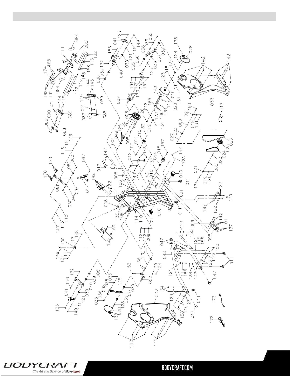
ProductPartsExplodedView-A
40
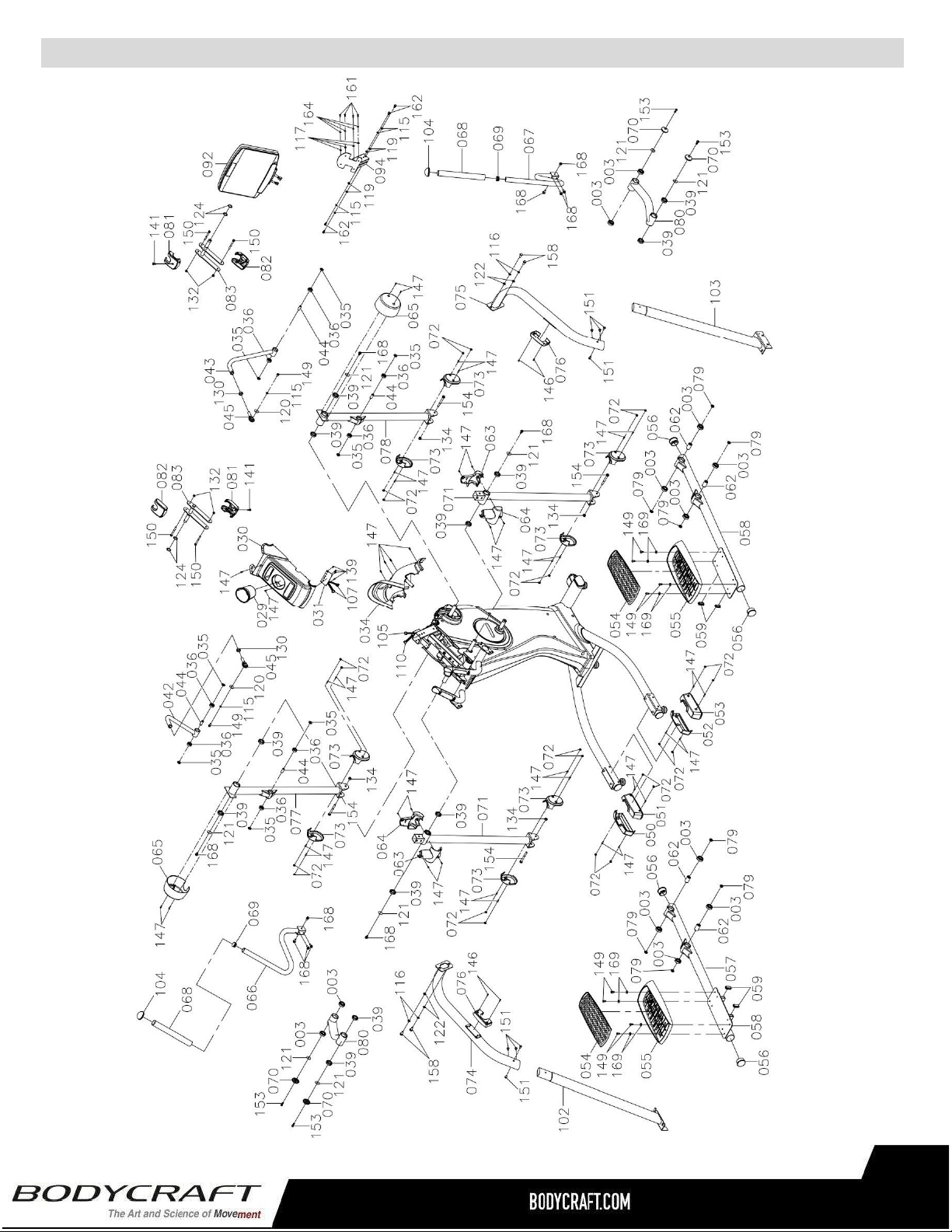
ProductPartsExplodedView-B
41

ResidentialWarranty:
Frame:Lifetime,Parts:10years,Console:3years,Labor:2years
HeadphoneJack,HDMI,CSAFE,ETHERNET&USBPort:90daysandLabor:None
CommercialWarranty:
Frame:10years,Parts:5years,Console:3years,andLabor:1year.
HeadphoneJack,HDMI,CSAFE,ETHERNET&USBPort:90daysandLabor:None
Thiswarrantyexcludesthefollowing:
1. Thewarrantydoesnotcovernormalmaintenanceorlaborchargesunlesslabortermsarelisted
above.
2. Normalcosmeticwearonpartssuchaspaint,seatcoverings,footrails,labelsandlogos.
3. Consumablessuchasbatteriesandheartratebeltsthatdonothaveareplaceablebattery.
4. Eprom/Softwareversionupgradesunlessdeterminedasnecessary.
5. Anyaccessoriesnotincludedintheoriginalpackaging.
*Thiswarrantyisinlieuofallwarranties,expressedorimplied,and/orallotherobligationsorliabilitieson
ourpart,andweneitherassumenorauthorizeanypersontoassumeforusanyotherobligationorliability
inconnectionwiththesaleofyourBODYCRAFTproduct.Undernocircumstancesshallwebeliableby
virtueofthiswarrantyorotherwisefordamagetoanypersonorpropertywhatsoeverforanyspecial,
indirect,incidental,secondaryorconsequentialdamageofanynaturewhatsoeverarisingoutoftheuseor
inabilitytousetheBODYCRAFTproduct.
Registeryourproduct’swarrantyatwww.bodycraft.com/product-registration.html
VALIDFORUSAANDCANADAONLY
(Pleaseconsultwithyourlocaldistributorforwarrantyinfospecifictoyourregion).
BODYCRAFTwarrantsitsproductstobefreeofdefectsinmaterialsandworkmanshipforthetimestated
belowtotheoriginalpurchaser.
Registeryourproductwithin30daysofpurchaseatwww.bodycraft.comorcall800-990-5556This
warrantyisvalidonlyinaccordancewiththefollowingconditions:
Thewarrantybeginsontheoriginalpurchasedateatretailandendswhentheoriginalowner
disposesofit,eitherthroughsale,gift,orotherwise.Thiswarrantyisnottransferableandisonlyvalidto
theoriginalpurchaser.
Thiswarrantyisavailableonlyforpurchasesmadewithinandtheoriginalpurchasercurrentlyresidingin
theUSAandCanada.Pleaseconsultwithyourlocaldistributorforwarrantyinformationspecifictoyour
region.Theproductmusthavebeenregisteredwithin30daysoftheoriginalpurchasedateorsupply
proofofpurchasetovalidatewarranty(originalsalesinvoice).
Thiswarrantydoesnotextendtoanylossesordamagesduetoaccident,misuse,abuse,neglect,
negligence,unauthorizedmodificationoralteration,usebeyondratedcapacity,unsuitablepowersourcesor
environmentalconditions,water,tampering,cosmeticdamages,orimproperinstallation,handling,repair,
maintenance,orapplication,orlackofpropermaintenance.
Iftheitemexhibitssuchadefect,BODYCRAFTwill,atitsoption,repairorreplaceitwithoutcostforparts.
Shippingandhandlingchargesmayapply.(BODYCRAFTmayrequirereturnofthepart(s)orphotographic
evidenceofthedamagedpart(s)priortoreplacement.)Serialnumberisrequired.
Partsrepairedorreplacedwillbewarrantedfortheremainderoftheoriginalwarrantyperiodonly.
ProductWarranty
42
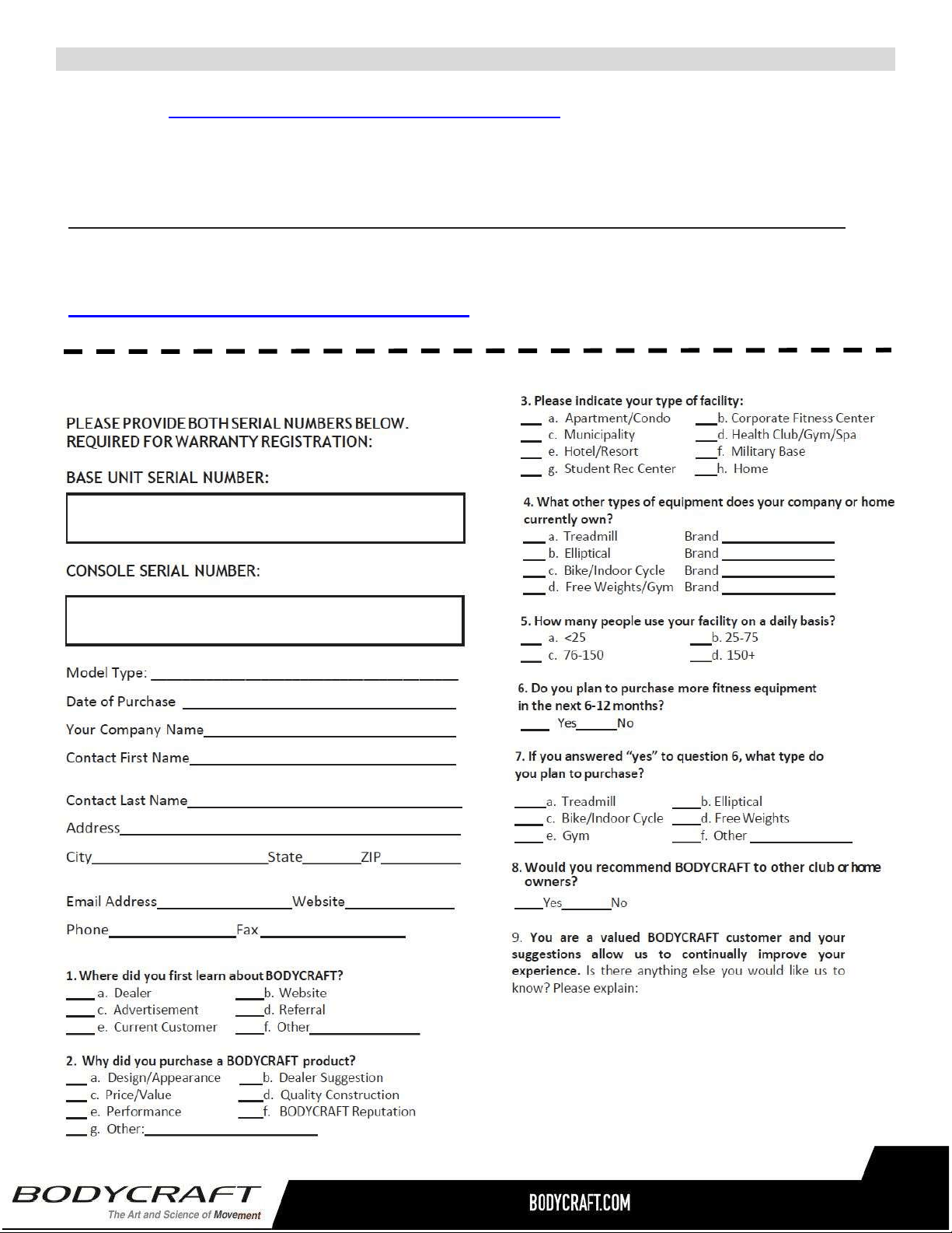
WarrantyRegistration
Thank you for purchasing a BODYCRAFT product. To validate the product warranty the fast and easy way, please go
on-line now to https://www.bodycraft.com/product-registration.html and register your product. The information
you provide will never be distributed to any other individuals or agencies for any purpose. If you prefer to mail
your warranty card, have the owner of the product complete the information below and return it to BODYCRAFT
within 30 days from the date of equipment installation.
PleaseNote:Failuretoregisterthisproductwillresultinnoservicingorauthorizationofpartstobeshipped.
To mail your warranty information, please fill in the information below and mail to: Service Dept., BODYCRAFT ,
7699 Green Meadows Dr. Lewis Center, Ohio 43035 (or save postage and register online at
https://www.bodycraft.com/product-registration.html )
WarrantyRegistration
43