ACC-CF-EH5C
고정형
천장마운트 키트
사용설명서
www.lge.co.kr
사용설명서를 읽고 난 후 사용하는 사람이 언제라도 볼 수 있는 장소에
보관하세요.
*MFL69532001*
P/No: MFL69532001 (1605-REV00)
Printed in Korea
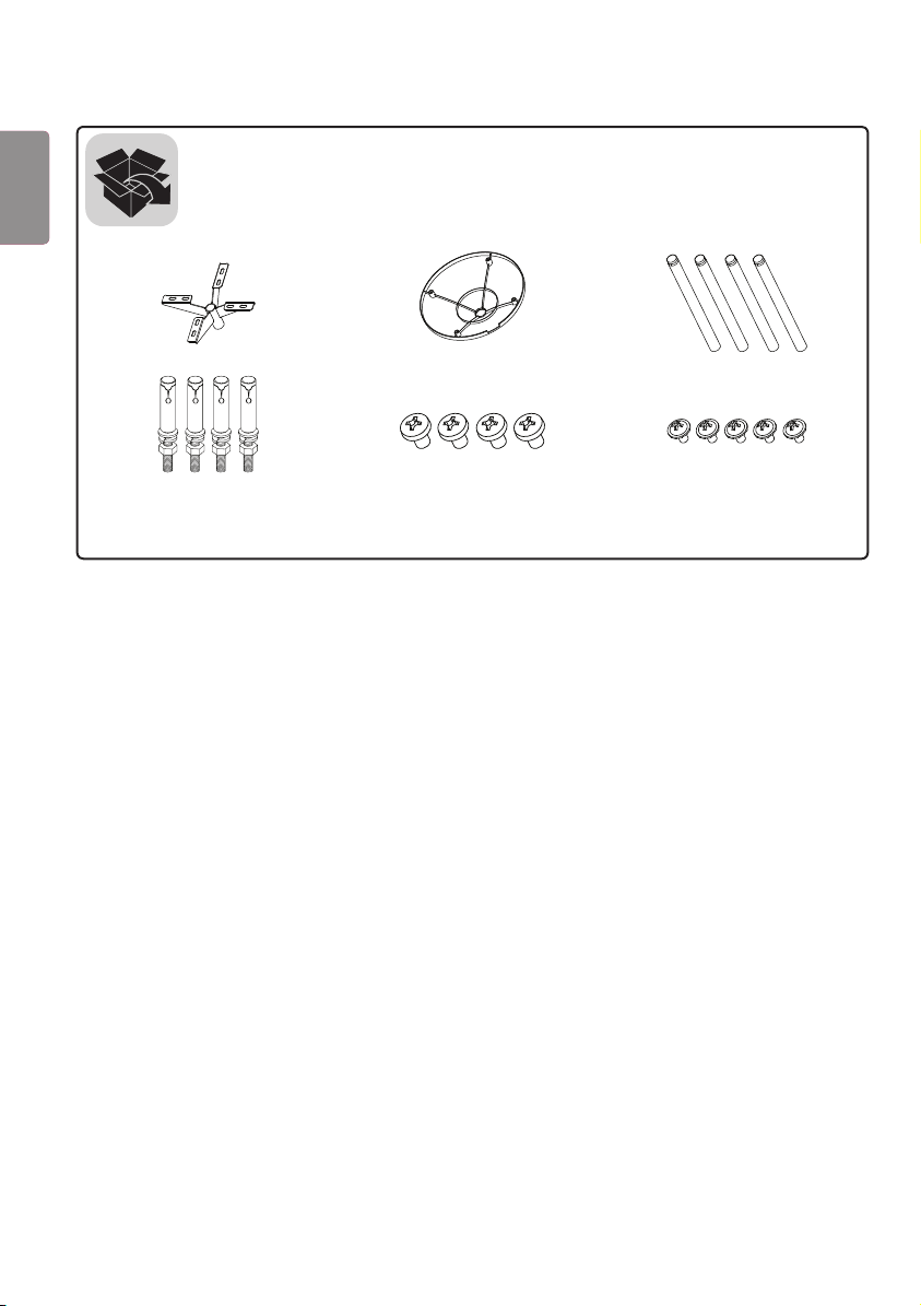
(M4 x L6) (M3 x L5.5)
2
ENG
한국어
주의
• 제품을 설치할 때 또는 제품 설치 후 높이 조정 시에는 반드시 두 사람 이상이 함께 하세요. 혼자서 하게 되면 제품이
떨어져 부상 또는 제품 파손의 원인이 될 수 있습니다.
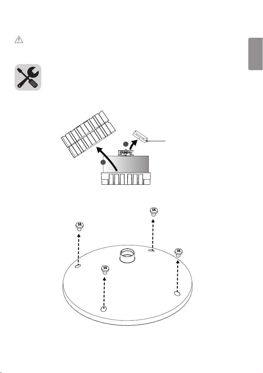
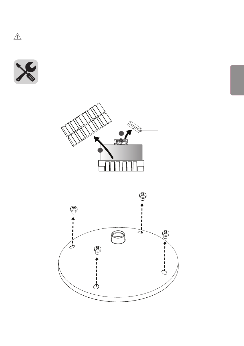
1 상자를 열고 위에 있는 포장 및 T-con 박스를 순서대로 제거합니다.
1
2
T-con 박스
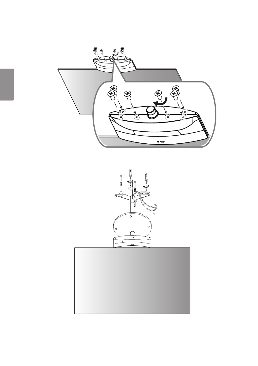
2 나사(M4 x L6) 4개를 풀어, 커버를 분리 합니다.
3
ENG한국어
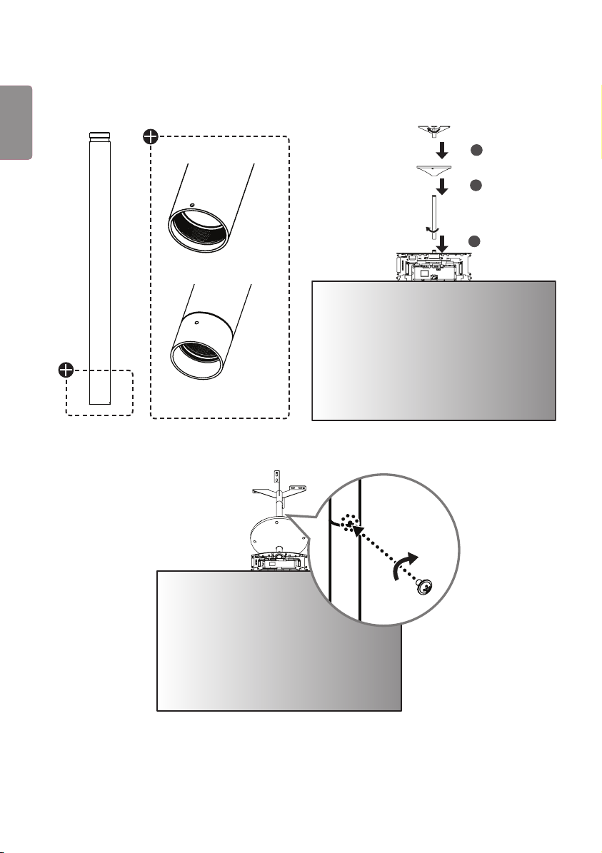
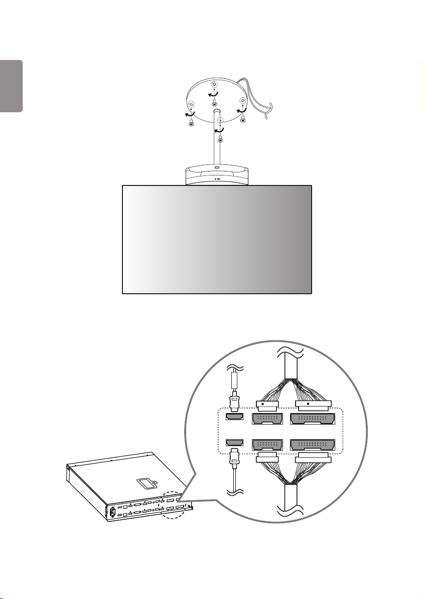
3 세트에 B 타입 파이프, 커버, 천장형 마운트를 순서대로 조립합니다. A 타입 파이프의 연결 개수 및 커버 설치는 선택
사항입니다.
1
2
3
A 타입
B 타입
4 파이프 연결부마다 고정용 나사 홀에 나사 (M3 x L5.5)를 체결하여 파이프를 고정시킵니다.
4
ENG
한국어
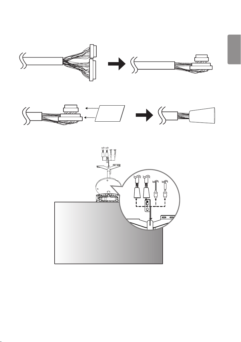
5 16/22 핀 케이블의 반대쪽 부분의 connector를 케이블과 일직선이 되도록 꺾어줍니다.
22
16
16
22
22
16
16
22
6 16/22 핀 connector를 함께 튜브에 삽입합니다.
16
22
16
22
7 정리된 16/22핀 케이블과 HDMI 케이블을 삽입하여 통과시키고, 분리된 세트를 재조립합니다.
FRONT
FRONT
5
ENG한국어
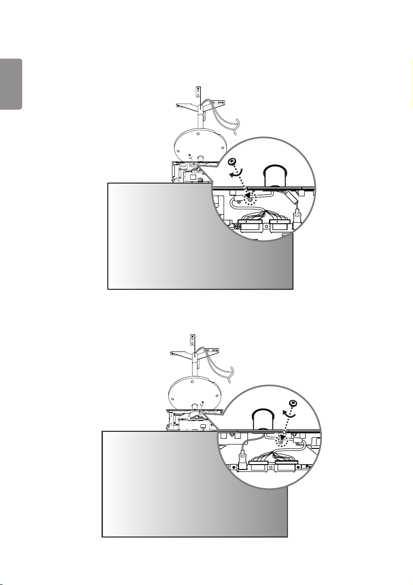
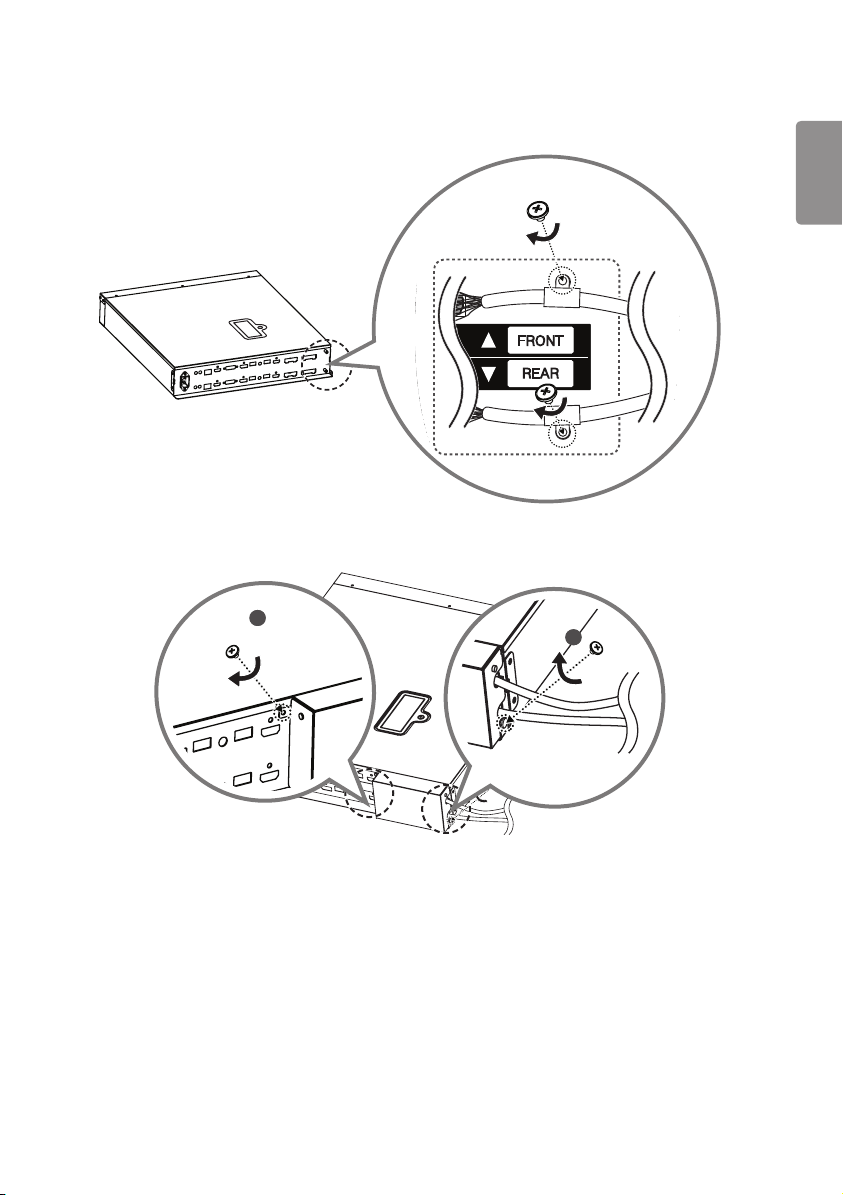
8 FRONT 라벨이 붙은 HDMI 케이블을 FRONT 면에 연결합니다. 붉은색 표시가 있는 16/22 핀 케이블에 케이블
홀더를 끼우고 나사 (M3 x L4.5)를 이용해 조립한 후 연결합니다.
22
FRONT
16
RR
22
FRONT
16
RR
9 FRONT 라벨이 없는 HDMI 케이블을 REAR 면에 연결합니다. 붉은색 표시가 없는 16/22 핀 케이블에 케이블
홀더를 끼우고 나사 (M3 x L4.5)를 이용해 조립한 후 연결합니다.
16
22
16
22
6
ENG
한국어
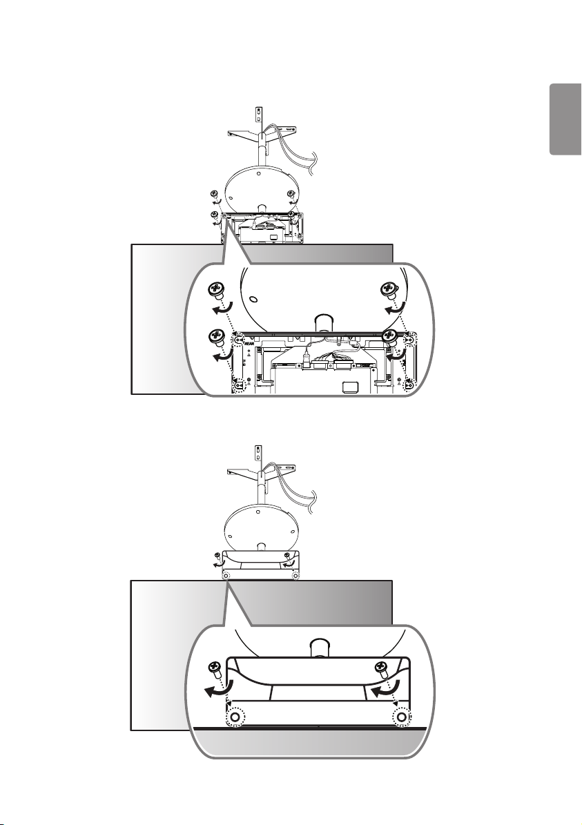
10 T-con 박스의 IR 수신부가 있는 면을 FRONT 면에 덮고, 반대쪽에서 나사 (Φ3 x L6) 4개로 체결합니다.
16
22
16
22
11
나머지 T-con 커버를 REAR 면에 덮고, 나사 (Φ3 x L10) 2개로 체결합니다.
7
ENG한국어
12
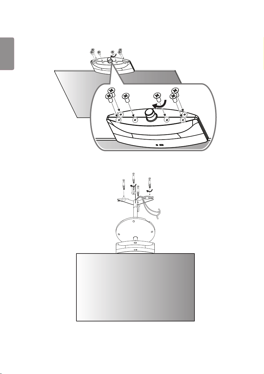
T-con 커버 하단에 나사 (M4 x L8) 6개를 체결합니다.
13
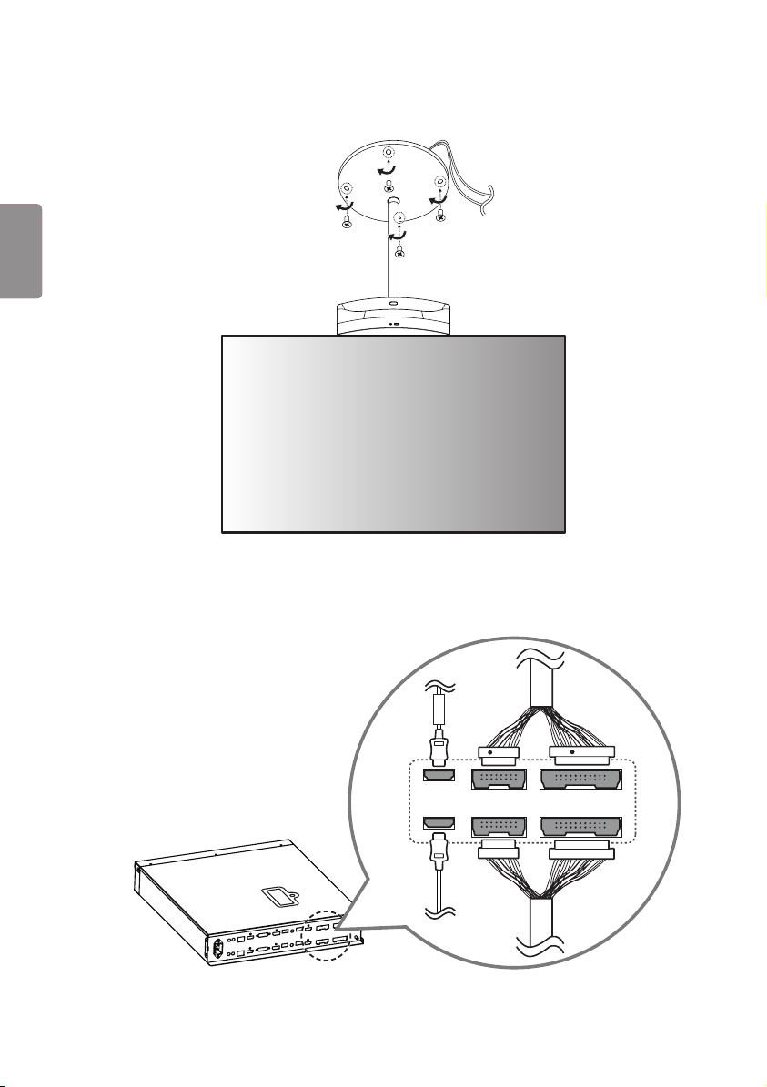
앵커 볼트 4개로 천장에 설치합니다.
8
ENG
한국어
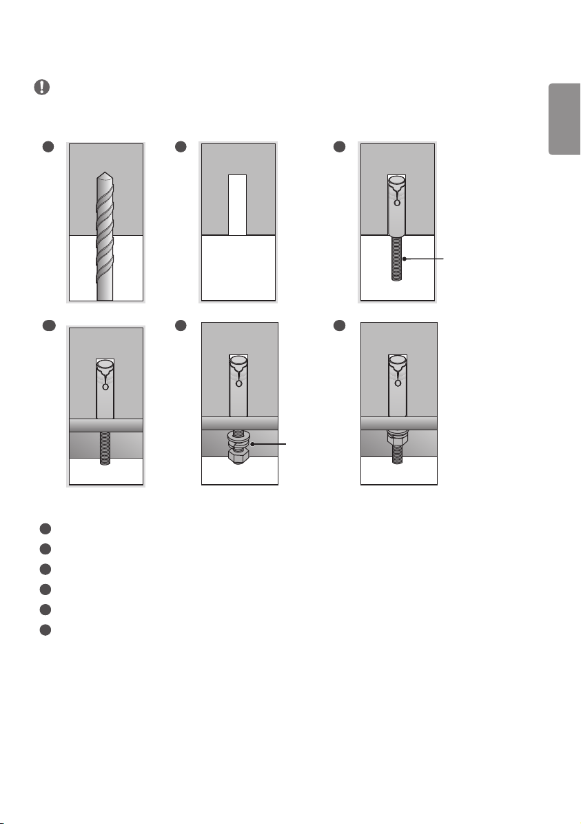
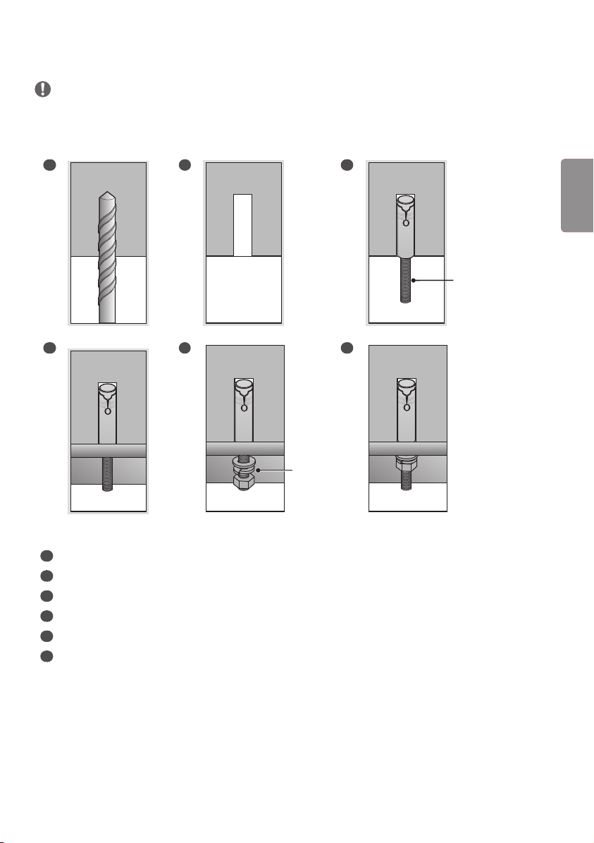
앵커 나사의 고정 방법
• 천장의 재질 및 마감재의 두께를 확인하세요. 천장의 재질이 금가지 않는 콘크리트 재질일 때만 동봉된 앵커 나사를
사용할 수 있습니다. 석고보드 또는 종이/나무 가루를 압축한 재질 (MDF)로 만들어진 천장에는 절대 설치하지 마세요.
1 2 3
천장 부착판 고정용
앵커 나사
4 5
와셔/
너트
6
1
앵커 위치에 구멍을 드릴 비트 (직경 14.5 mm)를 사용해 깊이 45 mm에서 55 mm 이내로 뚫으세요.
2
뚫은 구멍을 청소하세요.
3
구멍에 동봉된 앵커 나사를 삽입하세요.
4
나사의 위치에 맞게 천장부착판을 천장쪽으로 밀착시키세요.
5
와셔 및 너트를 순서대로 체결하세요. 이 때, 나사는 Torque 45 kgf/cm 이상으로 조이세요.
6
와셔 및 너트가 완전히 밀착 될 때까지 조이세요.
9
ENG한국어
14
나사 (M4 x L6) 4개로 커버를 고정합니다.
15
사이니지 박스에 케이블을 연결합니다. 이때, FRONT 라벨이 붙은 HDMI 케이블은 위에, FRONT 라벨이 없는 HDMI
케이블은 아래에 체결합니다. 16/22 핀 케이블의 경우 붉은색 표시가 있는 케이블을 위에 체결합니다.
16
16
22
22
FRONT
R
R
10
ENG
한국어
16
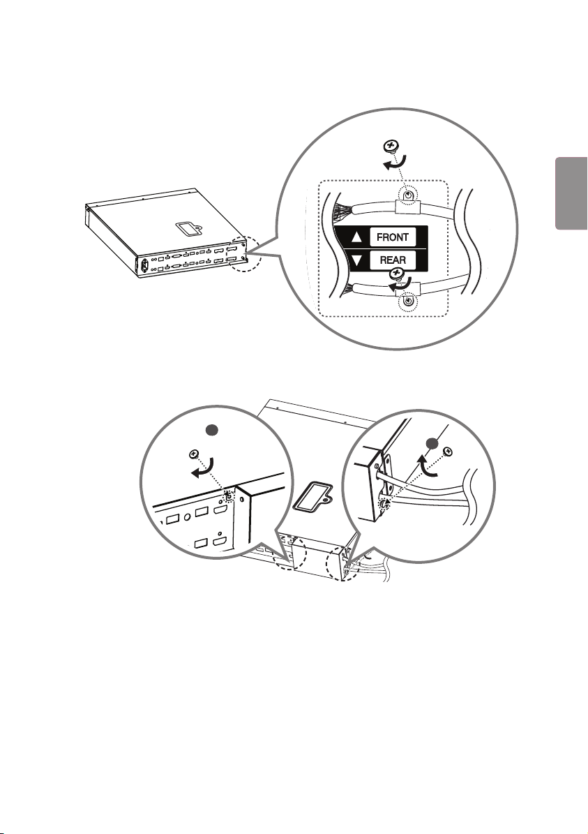
16/22 핀 케이블을 나사 (M3 x L4.5) 2개로 각각 체결합니다.
22
16
22
16
17
잭커버의 홈을 케이블에 맞춰 덮고 나사 (M3 x L4.5) 2개로 체결합니다.
1
2
11
ENG한국어
18
마운팅 브래킷을 나사 (M4 x L8) 4개로 사이니지 박스에 조립하여 설치합니다.
사이니지 박스에 전원코드를 연결합니다.
1
2
12
ENG
한국어


www.lg.com
Please read this manual carefully before operating your set and retain it
for future reference.
ACC-CF-EH5C
Fixed Ceiling
Mount Kit
OWNER’S MANUAL
(M4 x L6) (M3 x L5.5)
2
ENG
ENGLISH
CAUTION
• When installing or adjusting the height of this product, two or more people are required. If you try to install or adjust
the product alone, it may fall, causing personal injury or product damage.
1 Open the product box and remove the packaging materials and the T-con box in the order they appear.
1
2
T-con box
2 Loosen the four screws and remove the cover from ceiling mount.
3
ENGENGLISH
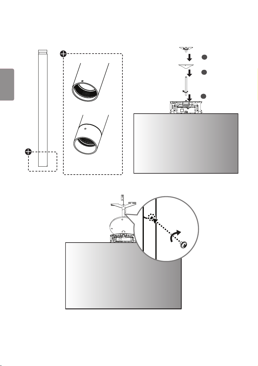
3 Assemble the B Type pipe, cover and ceiling mount in order. Additional A Type pipes and covers are optional.
1
2
3
A Type
B Type
4 Fasten a screw (M3 x L5.5) in each screw hole between the pipes to affix them together.
4
ENG
ENGLISH
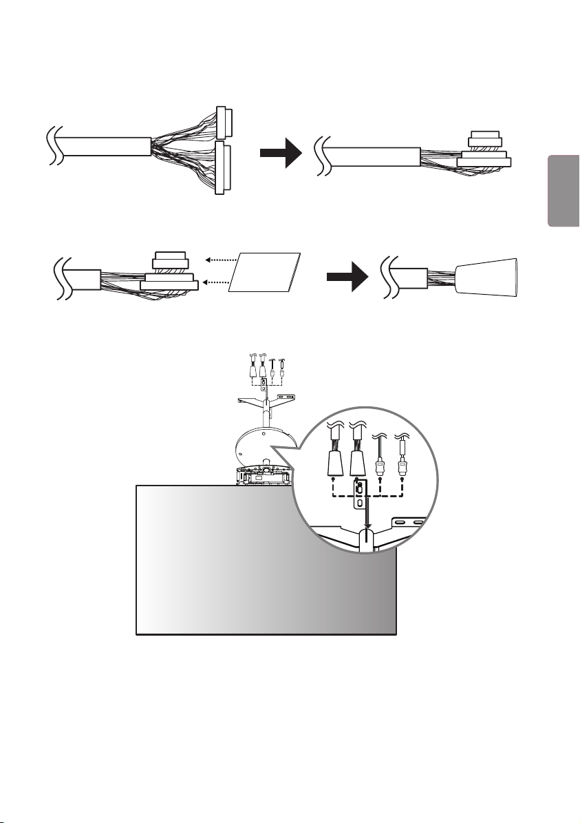
5 Fold the connectors on the opposite side of the 16/22-pin cables to make them parallel to the cable.
22
16
16
22
22
16
16
22
6 Insert the connectors of the 16/22-pin cables into the tubes.
16
22
16
22
7 Pass the arranged 16/22-pin cables and HDMI cables through the pipe, and reassemble the set.
FRONT
FRONT
5
ENGENGLISH

8 Connect the HDMI cable with the label marked "FRONT" to the FRONT side. Insert the 16/22-pin cable with the
red mark into the cable holder and attach it using a screw (M3 x L4.5).
22
FRONT
16
RR
22
FRONT
16
RR
9 Connect the HDMI cable without the label marked "FRONT" to the REAR side. Insert the 16/22-pin cable without
the red mark into the cable holder and attach it using a screw (M3 x L4.5).
16
22
16
22
6
ENG
ENGLISH
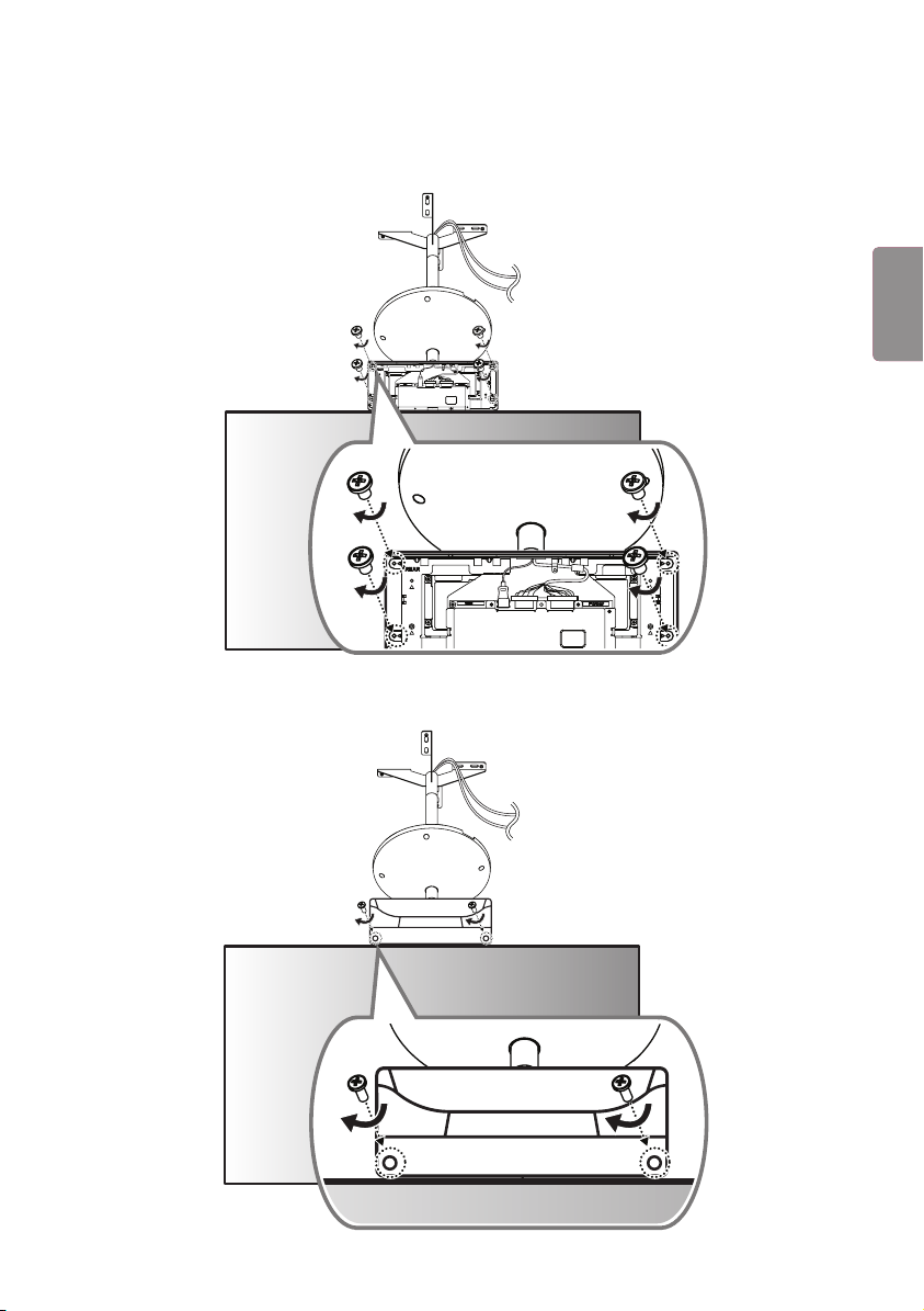
10 Cover the FRONT side with the side of the T-con box cover that has the IR receiver and attach it using four screws
(Φ3 x L6) on the opposite side.
16
22
16
22
11
Cover the REAR side with the other T-con box cover and attach it using two screws (Φ3 x L10).
7
ENGENGLISH
12
Fasten six screws (M4 x L8) to the bottom part of the T-con cover.
13
Install the device on the ceiling using four anchor bolts.
8
ENG
ENGLISH
FIXING THE ANCHOR SCREWS
• Check the ceiling material and the thickness of the finish material. The provided anchor screws can only be used if the
ceiling is made of concrete. Do not mount the device on ceilings made of plaster board or medium-density fiberboard
(MDF).
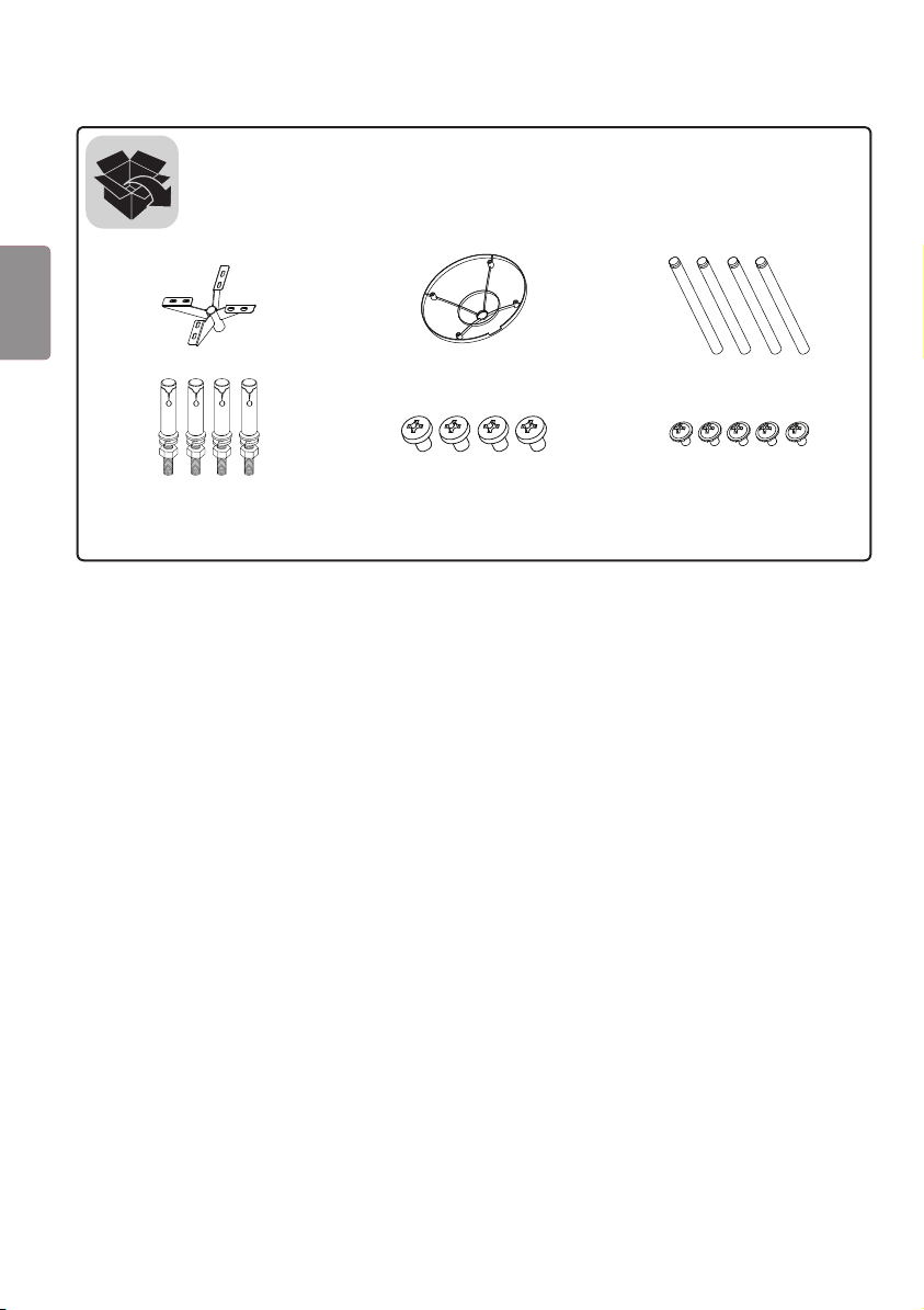
1 2 3
Anchor screw for
ceiling mount
4 5
Washer/
Nut
6
1
Drill a hole 45 mm to 55 mm deep using a 14.5 mm drill bit on the position you want to install your anchor.
2
Clean out the drilled hole.
3
Insert the provided anchor screw into the hole.
4
Place the ceiling mount close to the ceiling so it matches the position of the screws.
5
Fasten the washers and nuts in order. Tighten the screws using a torque of at least 45 kgf/cm.
6
Tighten the washers and nuts until they are completely fastened.
9
ENGENGLISH
14
Fix the cover in place using four screws (M4 x L6).
15
Connect the cables to the Signage box. Here, the HDMI cable with the FRONT label is attached to the top, and the
HDMI cable without the FRONT label is attached to the bottom. The 16/22-pin cable with the red mark must be
connected to the upper part.
16
16
22
22
FRONT
R
R
10
ENG
ENGLISH
16
Attach the 16/22-pin cables using two screws (M3 x L4.5).
22
16
22
16
17
Position the jack cover so the cables fit into the cut spaces and attach it using two screws (M3 x L4.5).
1
2
11
ENGENGLISH
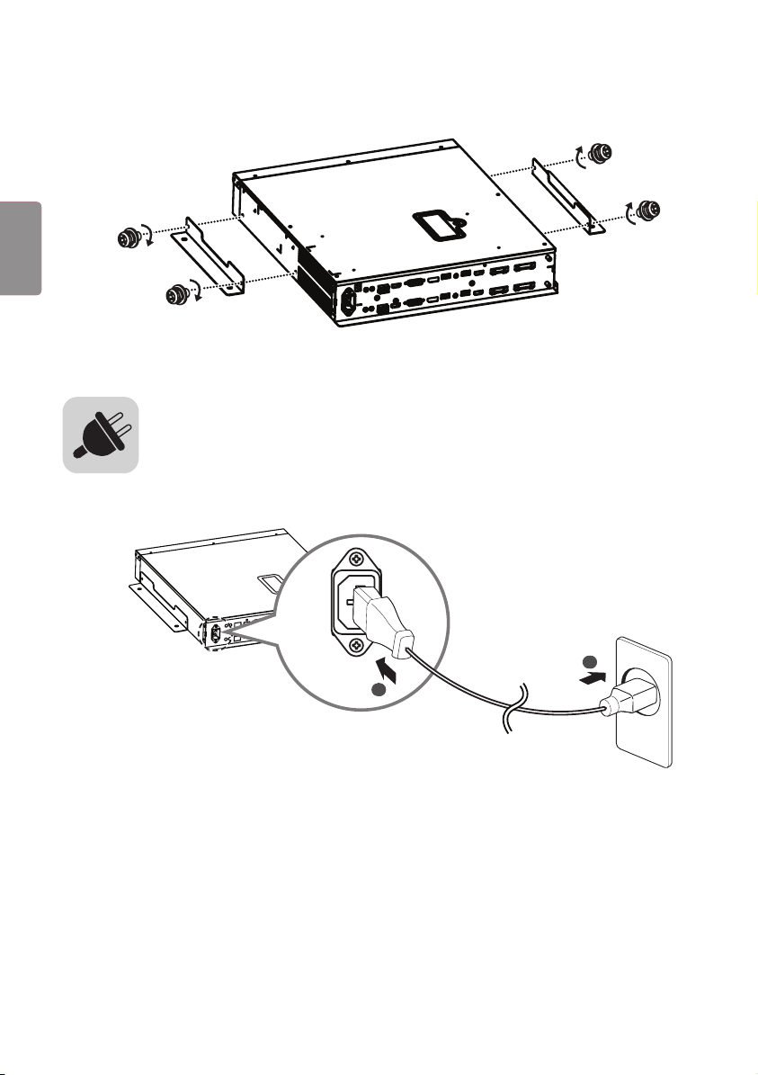
18
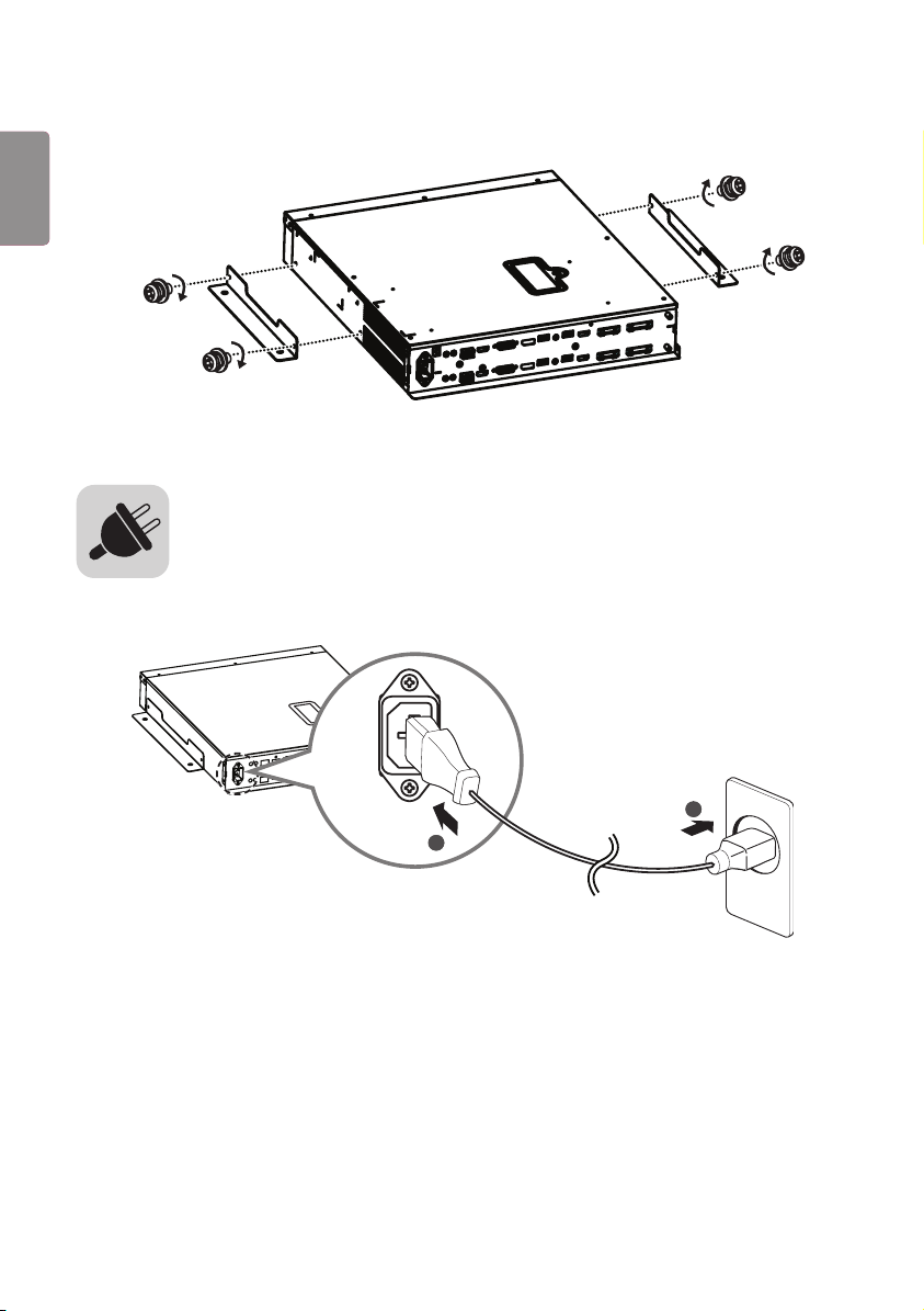
Attach the mounting brackets to the Signage box using four screws (M4 x L8).
Connect the power cable to the Signage box.
1
2
12
ENG
ENGLISH