Loading ...
Loading ...
Loading ...
HE240, HE280 HUMIDIFIER AND INSTALLATION KIT
11 69-2685ES—01
d. Insert the tubing into the saddle valve fitting and support the valve while
tightening the compression nut.
e. Insert plastic supply tubing into quick connect fitting. Insert fully, and apply
modest pull pressure to ensure a tight fit.
4. Use the following steps to install a
1/2 in. (13 mm) drain tube between the
humidifier and the floor drain (see Fig. 10).
a. Slide the drain clamp over the tubing.
b. Push the tubing over the drain nipple on
the humidifier.
c. Hand-tighten the clamp around the
tubing to secure it to the humidifier
drain. The clamp is tightened by
compressing the two sides together so
that one side fits into the ridged grove
on the other side.
d. Secure the tubing (can use foil tape)
along the route to prevent movement
and ensure downward slope for correct
drainage.
Fig. 10. Installing the drain tubing.
NOTE: Cut tubing to correct length so the tubing terminates at the drain.
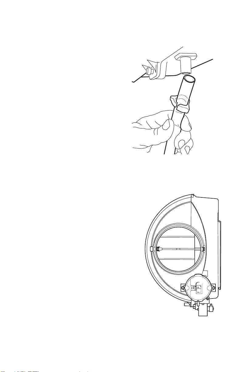
Connecting the Pressure Switch
1. If the humidifier is installed on the
supply duct (as is recommended),
the pressure switch needs to have
the tubing fed to the return duct.
If the humidifier is installed on the
return duct, the pressure switch
needs to have the tubing fed to
the supply duct.
2. Drill a 3/4-in. (19 mm) diameter
hole in the duct within 10 ft. (3 m)
of the switch to ensure the
provided tubing reaches the
pressure tap elbow.
Fig. 11. Pressure switch.
M20177
M33405
69-2685ES_A.book Page 11 Thursday, August 8, 2019 11:09 AM
Loading ...
Loading ...
Loading ...