
E:\STR-DA5500ES\4145850131\4145850131STRDA5500ESCEL\00COV-
STRDA5500ESCEL\120BCO.fm
masterpage: Left
STR-DA5500ES
4-145-850-13(1)
Printed in Malaysia
120BCO.fm Page 154 Thursday, July 23, 2009 6:03 PM
E:\STR-DA5500ES\4145850131\4145850131STRDA5500ESCEL\00COV-
STRDA5500ESCEL\010COV.fm
Master: Right
4-145-850-13(1)
STR-DA5500ES
©2009 Sony Corporation
STR-DA5500ES
4-145-850-13(1)
Operating Instructions
Multi Channel
AV Receiver
010COV.fm Page 1 Thursday, July 23, 2009 4:57 PM
2
GB
To reduce the risk of fire or electric
shock, do not expose this apparatus to
rain or moisture.
To reduce the risk of fire, do not cover the ventilation
opening of the apparatus with newspapers,
tablecloths, curtains, etc. Do not place the naked
flame sources such as lighted candles on the
apparatus.
Do not install the appliance in a confined space, such
as a bookcase or built-in cabinet.
To reduce the risk of fire or electric shock, do not
expose this apparatus to dripping or splashing, and
do not place objects filled with liquids, such as
vases, on the apparatus.
As the main plug is used to disconnect the unit from
the mains, connect the unit to an easily accessible
AC outlet. Should you notice an abnormality in the
unit, disconnect the main plug from the AC outlet
immediately.
Do not expose batteries or apparatus with battery-
installed to excessive heat such as sunshine, fire or
the like.
The unit is not disconnected from the mains as long
as it is connected to the AC outlet, even if the unit
itself has been turned off.
Excessive sound pressure from earphones and
headphones can cause hearing loss.
This symbol is intended to alert
the user to the presence of the Hot
Surface that may be hot if it is
touched during the normal
operation.
This equipment has been tested and found to comply
with the limits set out in the EMC Directive using a
connection cable shorter than 3 meters.
For customers in the United
States and Canada
This symbol is intended to alert the
user to the presence of uninsulated
“dangerous voltage” within the
product’s enclosure that may be of
sufficient magnitude to constitute a
risk of electric shock to persons.
This symbol is intended to alert the
user to the presence of important
operating and maintenance
(servicing) instructions in the
literature accompanying the
appliance.
ENERGY STAR
®
is a U.S. registered
mark.
As an ENERGY STAR
®
partner, Sony
Corporation has determined that this
product meets the ENERGY STAR
®
guidelines for energy efficiency.
For customers in the United
States
Owner’s Record
The model and serial numbers are located on the rear
of the unit. Record these numbers in the space
provided below. Refer to them whenever you call
upon your Sony dealer regarding this product.
Model No.
Serial No.
Important Safety Instructions
1) Read these instructions.
2) Keep these instructions.
3) Heed all warnings.
4) Follow all instructions.
5) Do not use this apparatus near water.
6) Clean only with dry cloth.
7) Do not block any ventilation openings. Install in
accordance with the manufacturer’s instructions.
8) Do not install near any heat sources such as
radiators, heat registers, stoves, or other
apparatus (including amplifiers) that produce
heat.
9) Do not defeat the safety purpose of the polarized
or grounding-type plug. A polarized plug has
two blades with one wider than the other. A
grounding type plug has two blades and a third
grounding prong. The wide blade or the third
prong are provided for your safety. If the
provided plug does not fit into your outlet,
WARNING

3
GB
consult an electrician for replacement of the
obsolete outlet.
10)Protect the power cord from being walked on or
pinched particularly at plugs, convenience
receptacles, and the point where they exit from
the apparatus.
11)Only use attachments/accessories specified by
the manufacturer.
12)Use only with the cart, stand, tripod, bracket, or
table specified by the manufacturer, or sold with
the apparatus. When a cart is used, use caution
when moving the cart/apparatus combination to
avoid injury from tip-over.
13)Unplug this apparatus during lightning storms or
when unused for long periods of time.
14)Refer all servicing to qualified service personnel.
Servicing is required when the apparatus has
been damaged in any way, such as power-supply
cord or plug is damaged, liquid has been spilled
or objects have fallen into the apparatus, the
apparatus has been exposed to rain or moisture,
does not operate normally, or has been dropped.
To reduce the risk of electric shock, the speaker cord
should be connected to the apparatus and the
speakers in accordance with the following
instructions.
1) Disconnect the AC power cord from the MAINS.
2) Strip 10 to 15 mm of the wire insulation of the
speaker cord.
3) Connect the speaker cord to the apparatus and
the speakers carefully so as not to touch the core
of speaker cord by hand. Also disconnect the AC
power cord from the MAINS before
disconnecting the speaker cord from the
apparatus and the speakers.
The following FCC statement
applies only to the version of
this model manufactured for
sale in the U.S.A. Other
versions may not comply with
FCC technical regulations.
NOTE:
This equipment has been tested and found to comply
with the limits for a Class B digital device, pursuant
to Part 15 of the FCC Rules. These limits are
designed to provide reasonable protection against
harmful interference in a residential installation.
This equipment generates, uses and can radiate radio
frequency energy and, if not installed and used in
accordance with the instructions, may cause harmful
interference to radio communications. However,
there is no guarantee that interference will not occur
in a particular installation. If this equipment does
cause harmful interference to radio or television
reception, which can be determined by turning the
equipment off and on, the user is encouraged to try
to correct the interference by one or more of the
following measures:
– Reorient or relocate the receiving antenna.
– Increase the separation between the equipment
and receiver.
– Connect the equipment into an outlet on a circuit
different from that to which the receiver is
connected.
– Consult the dealer or an experienced radio/TV
technician for help.
CAUTION
You are cautioned that any changes or modifications
not expressly approved in this manual could void
your authority to operate this equipment.
For customers in Europe
Notice for the customers:
the following information is only
applicable to equipment sold in
countries applying EU directives
The manufacturer of this product is Sony
Corporation, 1-7-1 Konan Minato-ku, Tokyo, 108-
0075 Japan. The Authorized Representative for
EMC and product safety is Sony Deutschland
GmbH, Hedelfinger Strasse 61, 70327 Stuttgart,
Germany. For any service or guarantee matters,
please refer to the addresses given in separate
service or guarantee documents.
Disposal of Old
Electrical & Electronic
Equipment (Applicable
in the European Union
and other European
countries with separate
collection systems)
This symbol on the product or
on its packaging indicates that
this product shall not be treated as household waste.
Instead it shall be handed over to the applicable
collection point for the recycling of electrical and
continued

4
GB
electronic equipment. By ensuring this product is
disposed of correctly, you will help prevent potential
negative consequences for the environment and
human health, which could otherwise be caused by
inappropriate waste handling of this product. The
recycling of materials will help to conserve natural
resources. For more detailed information about
recycling of this product, please contact your local
Civic Office, your household waste disposal service
or the shop where you purchased the product.
Disposal of waste
batteries (applicable in
the European Union and
other European
countries with separate
collection systems)
This symbol on the battery or on
the packaging indicates that the battery provided
with this product shall not be treated as household
waste. On certain batteries this symbol might be
used in combination with a chemical symbol. The
chemical symbols for mercury (Hg) or lead (Pb) are
added if the battery contains more than 0.0005%
mercury or 0.004% lead. By ensuring these batteries
are disposed of correctly, you will help prevent
potentially negative consequences for the
environment and human health which could
otherwise be caused by inappropriate waste
handling of the battery. The recycling of the
materials will help to conserve natural resources. In
case of products that for safety, performance or data
integrity reasons require a permanent connection
with an incorporated battery, this battery should be
replaced by qualified service staff only. To ensure
that the battery will be treated properly, hand over
the product at end-of-life to the applicable collection
point for the recycling of electrical and electronic
equipment. For all other batteries, please view the
section on how to remove the battery from the
product safely. Hand the battery over to the
applicable collection point for the recycling of waste
batteries. For more detailed information about
recycling of this product or battery, please contact
your local Civic Office, your household waste
disposal service or the shop where you purchased
the product.
About This Manual
• The instructions in this manual are for model
STR-DA5500ES (the receiver). Check your model
number by looking at the lower right corner of the
front panel.
• In this manual, the USA/Canadian model is used
for illustration purpose unless stated otherwise.
Any differences in operation are clearly indicated
in the text, for example, “European model only.”
• The instructions in this manual describe mostly the
controls on the supplied simple remote. You can
also use the controls on the receiver if they have
the same or similar names as those on the remote.
This receiver incorporates Dolby* Digital and Pro
Logic Surround and the DTS** Digital Surround
System.
* Manufactured under license from Dolby
Laboratories.
Dolby and the double-D symbol are trademarks
of Dolby Laboratories.
** Manufactured under license under U.S. Patent
#'s: 5,451,942; 5,956,674; 5,974,380; 5,978,762;
6,226,616; 6,487,535; 7,212,872; 7,333,929;
7,392,195; 7,272,567 & other U.S. and
worldwide patents issued & pending. DTS is a
registered trademark and the DTS logos,
Symbol, DTS-HD and DTS-HD Master Audio
are trademarks of DTS, Inc. © 1996-2008 DTS,
Inc. All Rights Reserved.
“Neural-THX” and “neural THX” introduced in the
Operating Instructions and displayed in the display
window and on the GUI menu screen mean Neural-
THX Surround.
This product using Neural-THX
®
Surround is
manufactured under license from Neural Audio
Corporation and THX Ltd. Sony Corporation hereby
grants the user a non-exclusive, non-transferable,
limited right of use to this product under USA and
foreign patent, patent pending and other technology
or trademarks owned by Neural Audio Corporation
and THX Ltd. “Neural Surround”, “Neural Audio”,
“Neural” and “NRL” are trademarks and logos
owned by Neural Audio Corporation, THX is a
trademark of THX Ltd., which may be registered in
some jurisdictions. All rights reserved.
On Copyrights

5
GB
This receiver incorporates High-Definition
Multimedia Interface (HDMI™) technology.
HDMI, the HDMI logo and High-Definition
Multimedia Interface are trademarks or registered
trademarks of HDMI Licensing LLC.
SIRIUS, XM and all related marks and logos are
trademarks of Sirius XM Radio Inc. and its
subsidiaries. All rights reserved. Service not
available in Alaska and Hawaii.
The font type (Shin Go R) installed in this receiver
is provided by MORISAWA & COMPANY LTD.
These names are the trademarks of MORISAWA &
COMPANY LTD., and the copyright of the font also
belongs to MORISAWA & COMPANY LTD.
iPod is a trademark of Apple Inc., registered in the
U.S. and other countries.
All other trademarks and registered trademarks are
of their respective holders. In this manual, ™ and ®
marks are not specified.
The Bluetooth word mark and logos are owned by
the Bluetooth SIG, Inc. and any use of such marks
by Sony Corporation is under license.
Other trademarks and trade names are those of their
respective owners.
“BRAVIA” Sync is a trademark of Sony
Corporation.
DLNA and DLNA CERTIFIED are trademarks and/
or service marks of the Digital Living Network
Alliance.
VAIO is a trademark of Sony Corporation.
Microsoft, Windows, Windows Vista, and Windows
Media are trademarks or registered trademarks of
Microsoft Corporation in the United States and/or
other countries.
Intel, Intel Core, and Pentium are trademarks or
registered trademarks of Intel Corporation or its
subsidiaries in the United States and other countries.
Rhapsody & the Rhapsody logo are trademarks and/
or registered trademarks of RealNetworks, Inc.
SHOUTcast
®
is a registered trademark of AOL
LLC.
THIS PRODUCT IS LICENSED UNDER THE
VC-1 PATENT PORTFOLIO LICENSE FOR THE
PERSONAL AND NON-COMMERCIAL USE OF
A CONSUMER TO
(i) ENCODE VIDEO IN COMPLIANCE WITH
THE VC-1 STANDARD (“VC-1 VIDEO”)
AND/OR
(ii) DECODE VC-1 VIDEO THAT WAS
ENCODED BY A CONSUMER ENGAGED IN A
PERSONAL AND NON-COMMERCIAL
ACTIVITY AND/OR WAS OBTAINED FROM A
VIDEO PROVIDER LICENSED TO PROVIDE
VC-1 VIDEO.
NO LICENSE IS GRANTED OR SHALL BE
IMPLIED FOR ANY OTHER USE. ADDITIONAL
INFORMATION MAY BE OBTAINED FROM
MPEG LA, L.L.C. SEE HTTP://
WWW.MPEGLA.COM
MPEG Layer-3 audio coding technology and patents
licensed from Fraunhofer IIS and Thomson.
“x.v.Color (x.v.Colour)” and “x.v.Color
(x.v.Colour)” logo are trademarks of Sony
Corporation.
This product incorporates copyright protection
technology that is protected by U.S. patents and
other intellectual property rights.
Use of this copyright protection technology must be
authorized by Macrovision, and is intended for
home and other limited viewing uses only unless
otherwise authorized by Macrovision.
Reverse engineering or disassembly is prohibited.

6
GB
Table of Contents
Description and location of parts ..................8
Getting Started
1: Installing speakers ..................................21
2: Connecting the monitor ..........................25
3a: Connecting the audio components ........27
3b: Connecting the video components .......32
3c: Connecting the IR Blaster .....................42
4: Connecting the antennas (aerials) ...........44
5: Connecting to the network .....................45
6: Preparing the receiver and the remote ....47
7: Setting the speakers ................................48
8: Calibrating the appropriate speaker settings
automatically (Auto Calibration) ...........50
9: Configuring the network settings of the
receiver ..................................................57
10: Preparing a computer to use as a
server .....................................................58
Guide to on-screen display operation .........59
Playback
Enjoying sound/images from the component
connected to the receiver .......................62
Enjoying sound/images from the components
connected to the DIGITAL MEDIA
PORT .....................................................64
Operating the TDM-iP50 using the GUI menu
of the receiver ........................................65
Tuning
Listening to FM/AM radio .........................68
Presetting FM/AM radio stations ...............71
Listening to satellite radio
(USA/Canadian model only) .................73
Connecting a satellite radio tuner ...............74
Preparing to listen to a satellite radio .........74
Selecting a channel of the satellite radio ....75
Presetting satellite radio channels ..............77
Restricting access to specific channels
(Parental Lock) (SIRIUS only) ............. 78
Enjoying Surround Sound
Playing back with 2-channel sound ........... 82
Playing back with multi-channel
surround ................................................ 83
Enjoying a surround effect for music ......... 86
Enjoying a surround effect for movies ....... 88
Using Network Features
About the network functions of the
receiver .................................................. 92
What you can do with the home network
function ................................................. 93
Enjoying content stored on the server ........ 96
Listening to Rhapsody ............................... 98
Listening to SHOUTcast .......................... 101
Features of the ES Utility application
software ............................................... 103
Using Multi-zone Features
What you can do with the Multi-zone
function ............................................... 105
Making a multi-zone connection ............. 106
Setting the speakers in zone 2 .................. 108
Switching the zone setting of the
remote ................................................. 109
Operating the receiver from another zone
(ZONE 2/ZONE 3 operations) ............ 109
Listening to the same music in different zone
(Party Mode) ....................................... 110

7
GB
Using Other Features
Using “BRAVIA” Sync features .............. 112
Switching the monitors that output the HDMI
video signals ........................................ 116
Outputting the HDMI signals even when the
receiver is in standby mode
(Pass Through) .................................... 117
Switching between digital and analog
audio .................................................... 118
Enjoying the sound/images from other inputs
(Input Assign) ..................................... 119
Using the sleep timer ................................ 121
Enjoying the surround effect at low volume
levels ................................................... 122
Recording using the receiver .................... 123
Switching the command mode of the receiver
and the remote ..................................... 124
Using a bi-amplifier connection ............... 126
Adjusting Settings
Using the setting menu ............................. 127
Auto Calibration ....................................... 128
Speaker settings ........................................ 130
Surround settings ...................................... 134
EQ settings ............................................... 136
Multi Zone settings .................................. 136
Audio settings .......................................... 138
Video settings ........................................... 140
HDMI settings .......................................... 142
Network settings ...................................... 144
Quick Click settings ................................. 145
System settings ......................................... 146
Operating without connecting to a TV ..... 147
Operating Each Component
Using the On-screen Remote
(Quick Click)
Operating components or lighting connected
to the receiver using the on-screen remote
(Quick Click) ...................................... 153
Using Quick Click .................................... 154
Setting components that are operated by the
on-screen remote .................................160
Performing several commands in sequence
automatically with Quick Click (Macro
Play) ....................................................165
Setting remote control codes that are not
stored in Quick Click ...........................167
Resetting the remote code for Quick
Click ....................................................168
Operating Each Component
Using the Multifunction
Remote
Operating each component using the
multifunction remote ...........................170
Programming the remote ..........................172
Performing several commands in sequence
automatically (Macro Play) .................175
Setting remote commander codes that are not
stored in the remote .............................177
Clearing all the contents of the remote’s
memory ................................................179
Additional Information
Glossary ....................................................180
Precautions ...............................................184
Troubleshooting ........................................185
Specifications ...........................................192
Index .........................................................195
8
GB
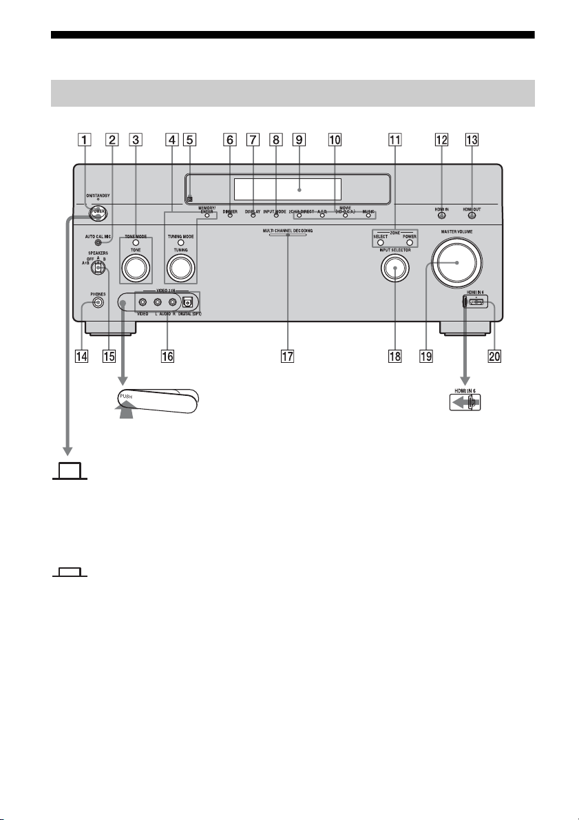
Description and location of parts
Front panel
Status of the POWER button
Off
The receiver is turned off (initial
setting).
Press POWER to turn the receiver on.
You cannot turn the receiver on using
the remote.
On/Standby
Press
?/1 on the remote to turn the
receiver on or set it to the standby mode.
When you press POWER on the
receiver, the receiver will be turned off.
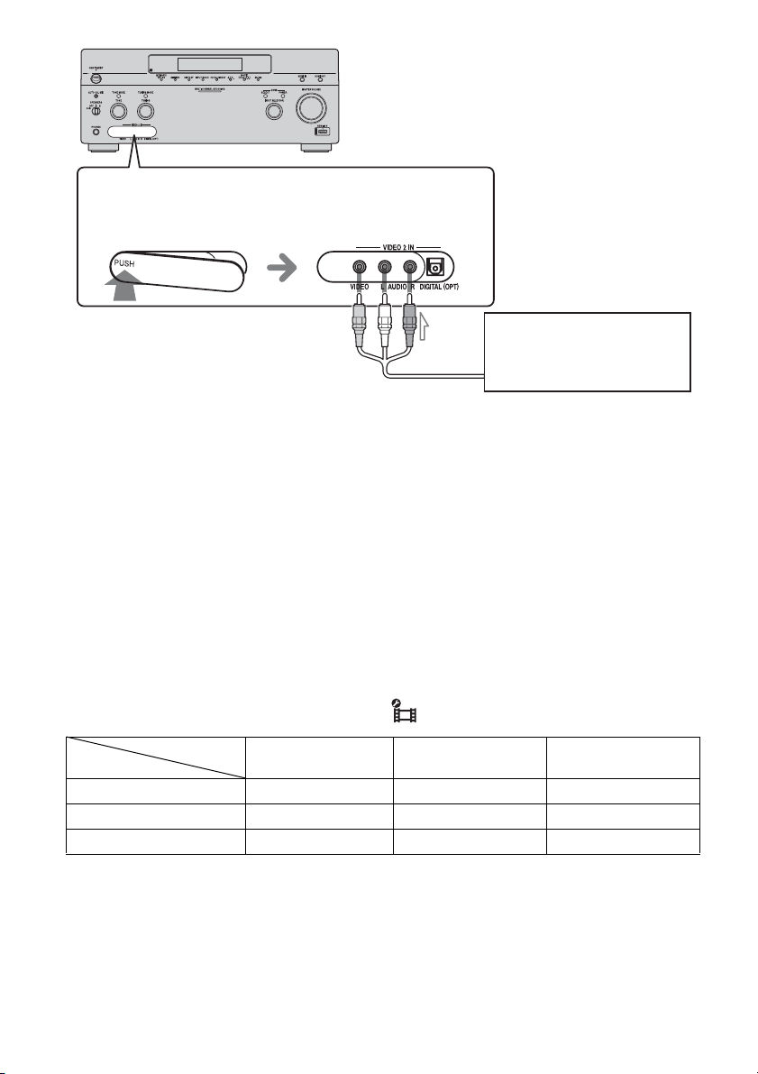
To remove the cover
Press PUSH.
When you remove the cover, keep it out
of reach from children.
To open the cover
Slide the cover to the
left.

9
GB
Name Function
A POWER Press to turn the
receiver on or off.
B AUTO CAL MIC
jack
Connects to the
supplied optimizer
microphone for the
Digital Cinema Auto
Calibration function
(page 51).
C TONE MODE Adjusts FRONT,
CENTER,
SURROUND/
SURROUND BACK
BASS and TREBLE.
Press TONE MODE
repeatedly to select
BASS or TREBLE,
then turn TONE to
adjust the level.
TONE
D MEMORY/
ENTER
Press to operate a tuner
(FM/AM) and satellite
radio (XM/SIRIUS)
(USA/Canadian model
only).
TUNING MODE
TUNING
E Remote sensor Receives signals from
remote commander.
F DIMMER Press repeatedly to
adjust brightness of the
display.
G DISPLAY Press repeatedly to
select information
displayed on the
display.
H INPUT MODE Press to select the input
mode when the same
components are
connected to both
digital and analog jacks
(page 118).
I Display
window
The current status of
the selected component
or a list of selectable
items appears here
(page 11).
J 2CH/A.DIRECT Press to select sound
field (page 82, 83, 86,
88).
A.F.D.
MOVIE
(HD-D.C.S.)
MUSIC
K ZONE/
SELECT,
POWER
Press SELECT
repeatedly to select
zone 2, zone 3 or main
zone. Each time you
press POWER, the
output signals for the
selected zone will be
turned on or off
(page 105).
L HDMI IN Press to select the input
signal from the
component connected
to the HDMI IN jacks
(page 33).
M HDMI OUT Press to select output
signal to the component
connected to the HDMI
OUT jacks (page 33).
N PHONES jack Connects to
headphones.
O SPEAKERS
(OFF/A/B/A+B)
Switch to OFF, A, B,
A+B of the front
speakers (page 50).
P VIDEO 2 IN
jacks
Connect to a portable
audio/video component
such as a camcorder or
video game.
Q MULTI
CHANNEL
DECODING
lamp
Lights up when multi-
channel audio signals
are decoded.
Name Function
continued

10
GB
R INPUT
SELECTOR
Turn to select the input
source to play back.
To select the input
source for zone 2 or
zone 3, press ZONE
SELECT (
qa) to select
zone 2 or zone 3 first
(“ZONE 2 INPUT” or
“ZONE 3 INPUT”
appears on the display),
then turn INPUT
SELECTOR to select
the input source.
S MASTER
VOLUME
Turn to adjust the
volume level of all
speakers at the same
time.
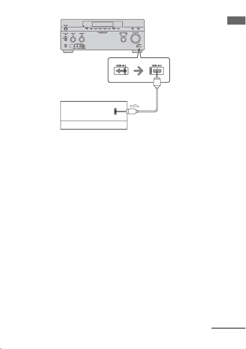
T HDMI IN 6 Connect to a
camcorder. The video
and sound from your
camcorder is input
(page 33).
Name Function
11
GB
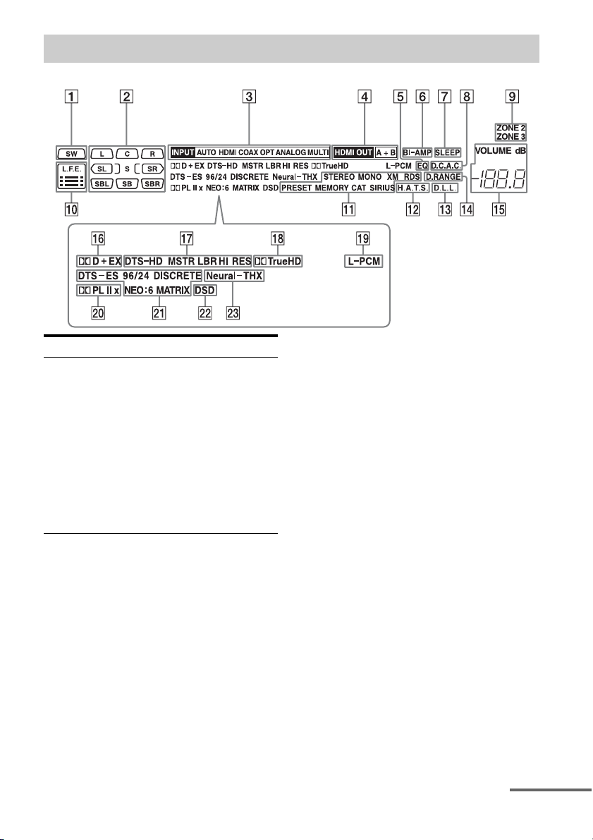
Indicators on the display
Name Function
A SW Lights up when subwoofer
is connected and the audio
signal is output from the
SUBWOOFER jack. While
this indicator lights up, the
receiver creates a
subwoofer signal based on
the L.F.E. signal in the disc
being played back or the
low frequency components
of the front channels.
continued

12
GB
B Playback
channel
indicators
The letters (L, C, R, etc.)
indicate the channels being
played back. The boxes
around the letters vary to
show how the receiver
downmixes the source
sound (based on the speaker
settings).
L Front Left
RFront Right
C Center (monaural)
SL Surround Left
SR Surround Right
S Surround (monaural or the
surround components
obtained by Pro Logic
processing)
SBL Surround Back Left
SBR Surround Back Right
SB Surround Back (the
surround back components
obtained by 6.1 channel
decoding)
Example:
Recording format (Front/
Surround): 3/2.1
Output channel: Surround
speakers are set to “NO.”
Sound Field: A.F.D. AUTO
Name Function
LSW
SL
SR
CR
C Input
indicators
Light up to indicate the
current input.
INPUT Lights up constantly with
either following the
corresponding indicators
that indicate the current
input status.
AUTO Lights up with the
corresponding indicators
that indicate the current
input when INPUT MODE
is set to “Auto.”
HDMI The receiver recognizes a
component connected via
an HDMI IN jack.
COAX Digital signal is input
through the COAXIAL
jack.
OPT Digital signal is input
through the OPTICAL jack.
ANALOG No digital signal is being
input. When INPUT
MODE is set to “Analog,”
or when the “2ch Analog
Direct” is being selected, it
also lights up.
MULTI The multi-channel input is
selected.
D HDMI OUT
A+B
Lights up when the signals
are output from the HDMI
OUT A or B jack. + also
lights up, along with A and
B when the signals are
output from both jacks.
E EQ Lights up when the
equalizer is activated.
F BI-AMP Lights up when surround
back speakers selection is
set to “BI-AMP.”
G SLEEP Lights up when the sleep
timer is activated.
Name Function

13
GB
H D.C.A.C. Lights up when auto
calibration is activated.
I ZONE 2/
ZONE 3
Lights up while operation in
zone 2/zone 3 is being
enabled.
J L.F.E. Lights up when the disc
being played back contains
an L.F.E. (Low Frequency
Effects) channel. The L.F.E.
channel signal is actually
being reproduced, the bars
underneath the letters light
up to indicate the level.
Since the L.F.E. signal is
not recorded in all parts of
the input signal, the bar
indication will fluctuate
(and may turn off) during
playback.
Name Function
K Tuning
indicators
Lights up when the receiver
tunes in radio stations, or
satellite radio stations.
STEREO Stereo broadcast
MONO Monaural broadcast
XM
(USA/
Canadian
model only)
The XM Mini-Tuner and
Home Dock are connected
and “XM” is selected.
SIRIUS
(USA/
Canadian
model only)
The SiriusConnect Home
tuner is connected and
“SIRIUS” is selected.
CAT
(USA/
Canadian
model only)
The category mode is
selected during the satellite
radio operation.
RDS
(European
model only)
RDS information is
received.
PRESET The tuning mode is set to
the preset mode.
MEMORY A memory function, such as
Name Input, etc., is
activated.
L H.A.T.S. Lights up when the
H.A.T.S. (High quality
digital Audio Transmission
System) function is
activated.
M D.L.L. Lights up when the D.L.L.
(Digital Legato Linear)
function is activated.
N D.RANGE Lights up when dynamic
range compression is
activated.
O VOLUME Displays the current
volume.
Name Function
continued

14
GB
P Dolby
Digital
Surround
indicators
Lights up one of the
respective indicators when
the receiver is decoding the
corresponding Dolby
Digital format signals.
;D Dolby Digital
;D+ Dolby Digital Plus
;D EX Dolby Digital Surround EX
Note
When playing a Dolby Digital
format disc, be sure that you
have made digital connections
and that INPUT MODE is not
set to “Analog.”
Q DTS-HD
indicators
Light up when the receiver
is decoding DTS-HD.
DTS-HD Lights up constantly with
the one of the following
indicators.
MSTR DTS-HD Master Audio
LBR DTS-HD Low Bit Rate
Audio
HI RES DTS-HD High Resolution
Audio
R ;TrueHD Lights up when the receiver
is decoding Dolby TrueHD.
S L-PCM Lights up when Linear
PCM (Pulse Code
Modulation) signals are
input.
Name Function
T Dolby
Pro Logic
indicators
Lights up one of the
respective indicators when
the receiver performs Dolby
Pro Logic processing. This
matrix surround decoding
technology can enhance
input signals.
;PL Dolby Pro Logic
;PLII Dolby Pro Logic II
;PLIIx Dolby Pro Logic IIx
Note
This indicator does not light
when either the center speaker
and surround speaker is not
connected.
U DTS(-ES)
indicators
Light up when DTS or
DTS-ES signals are input.
DTS Lights up when the receiver
is decoding DTS signals.
Either 96/24 or NEO:6 also
lights up depending on the
input signal format or
decoding format.
96/24 DTS 96/24 (96 kHz/24 bit)
decoding
NEO:6 DTS Neo:6 Cinema/Music
DTS-ES Lights up with the either
following indicator
depending on the input
signal decoding format.
DISCRETE DTS-ES Discrete 6.1
MATRIX DTS-ES Matrix 6.1
Note
When playing a DTS format
disc, be sure that you have
made digital connections and
that INPUT MODE is not set to
“Analog.”
V DSD Lights up when the receiver
is receiving DSD (Direct
Stream Digital) signals.
W Neural-THX Lights up when the receiver
applies Neural-THX
processing to input signals.
Name Function
15
GB
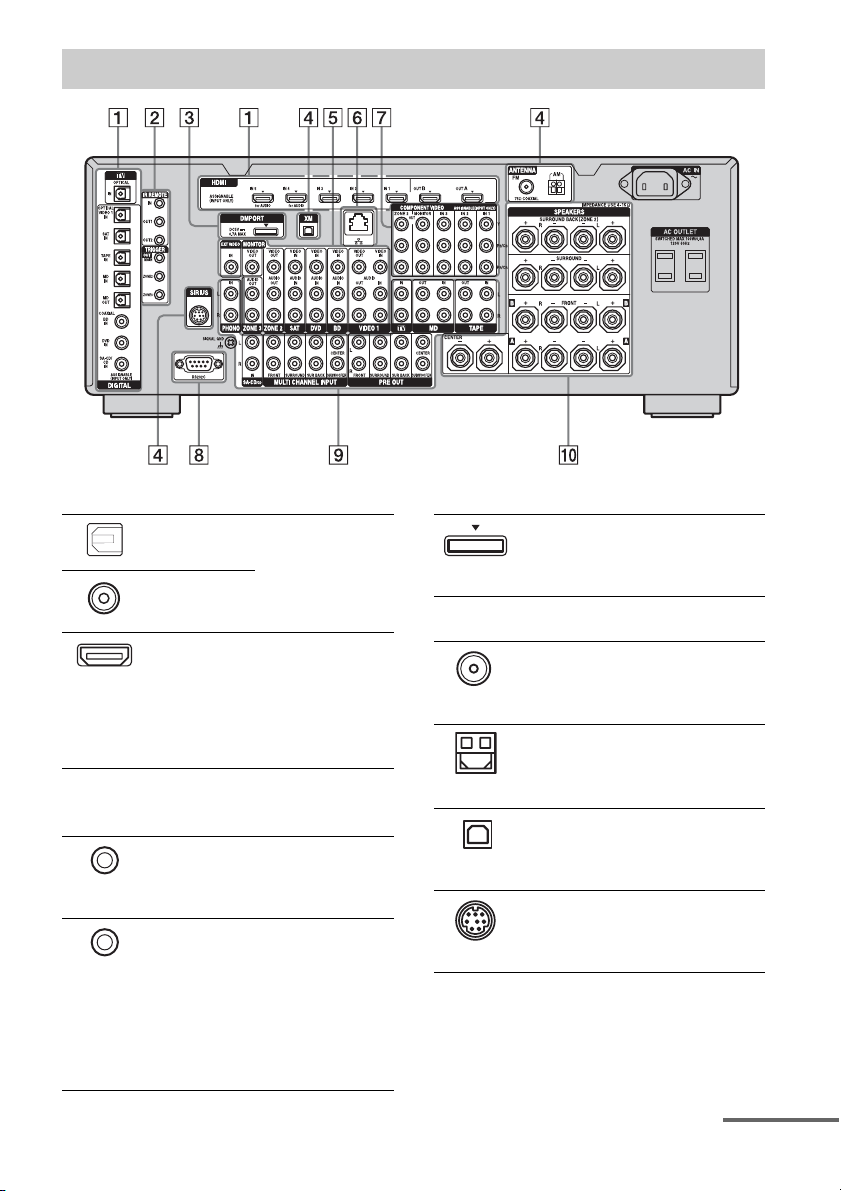
Rear panel
A DIGITAL INPUT/OUTPUT section
OPTICAL IN/
OUT jacks
Connect to a DVD
player, Super Audio
CD player, etc. (page
25, 28, 34, 37, 38).
COAXIAL IN
jacks
HDMI IN/
OUT* jacks
Connect to a DVD
player, Blu-ray Disc
Player, or a satellite
tuner. An image and
the sound are output
to TV or a projector
(page 25, 33).
B Control jacks for Sony equipment
and other external components
IR REMOTE
IN/OUT jacks
Connect an IR
repeater (page 105)
or an IR Blaster
(page 42).
TRIGGER
OUT jacks
Connect to interlock
on/off of the power
supply of other 12V
TRIGGER
compliant
components, or the
amplifier/receiver of
zone 2 or zone 3
(page 137).
C DMPORT
Connect to a Sony
DIGITAL MEDIA
PORT adapter
(page 28).
D ANTENNA section
FM ANTENNA
jack
Connects to the FM
wire antenna (aerial)
supplied with this
receiver (page 44).
AM
ANTENNA
jack
Connects to the AM
loop antenna (aerial)
supplied with this
receiver (page 44).
XM jack
(USA/Canadian
model only)
Connects to the XM
Mini-Tuner and
Home Dock (not
supplied) (page 74).
SIRIUS jack
(USA/Canadian
model only)
Connects to a
SiriusConnect Home
tuner (not supplied)
(page 74).
continued
16
GB
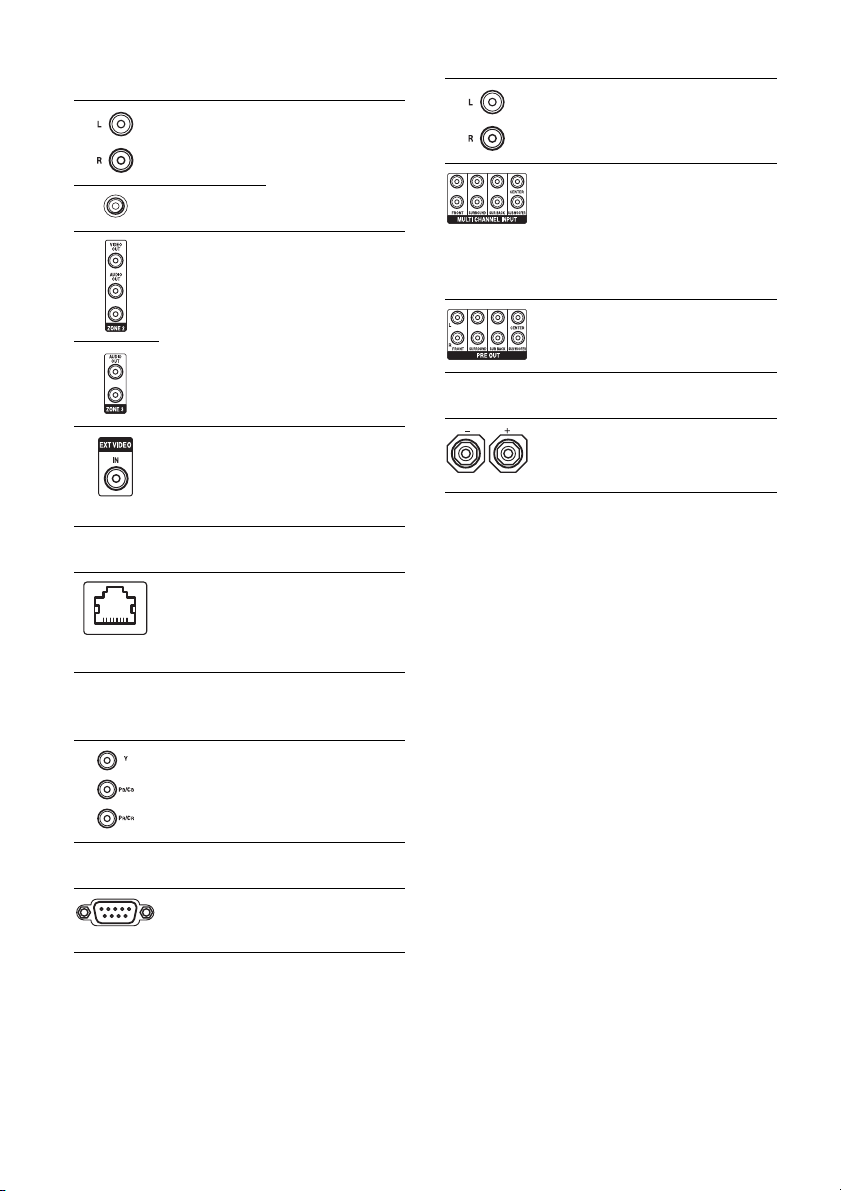
* You can watch the selected input image when you
connect the HDMI OUT or MONITOR OUT jacks
to a TV (page 25).
E VIDEO/AUDIO INPUT/OUTPUT
section
AUDIO IN/
OUT jacks
Connect to a VCR or
a DVD player etc.
(page 25, 37, 38, 39).
VIDEO IN/
OUT* jacks
AUDIO OUT
jacks
VIDEO OUT
jack
Connect to the
component in zone 2
or zone 3 (page 105).
EXT VIDEO IN
jack
Connects to the
component when
you want to watch in
PIP (Picture in
Picture) window.
F LAN port
Connects to the
router when you
want to connect the
receiver to your
network.
G COMPONENT VIDEO INPUT/
OUTPUT section
Y, P
B
/C
B
, P
R
/
C
R
IN/OUT*
jacks
Connect to a DVD
player, TV, or a
satellite tuner (page
25, 37, 38).
H RS232C port
Used for
maintenance and
service.
I AUDIO INPUT/OUTPUT section
AUDIO IN/
OUT jacks
Connect to a tape
deck or MD deck, etc
(page 31).
MULTI
CHANNEL
INPUT jacks
Connect to a Super
Audio CD player or
DVD player with an
analog audio jack for
7.1 channel or 5.1
channel sound
(page 30).
PRE OUT jacks Connect to an
external power
amplifier.
J SPEAKERS section
Connects to speakers
(page 23).
17
GB
You can use the supplied remote to operate the
receiver and to control the Sony audio/video
components that the remote is assigned to
operate.
Simple remote commander
(RM-AAU061)
This remote can only be used to operate the
receiver. You can control the main functions of
the receiver with simple operations using this
remote.
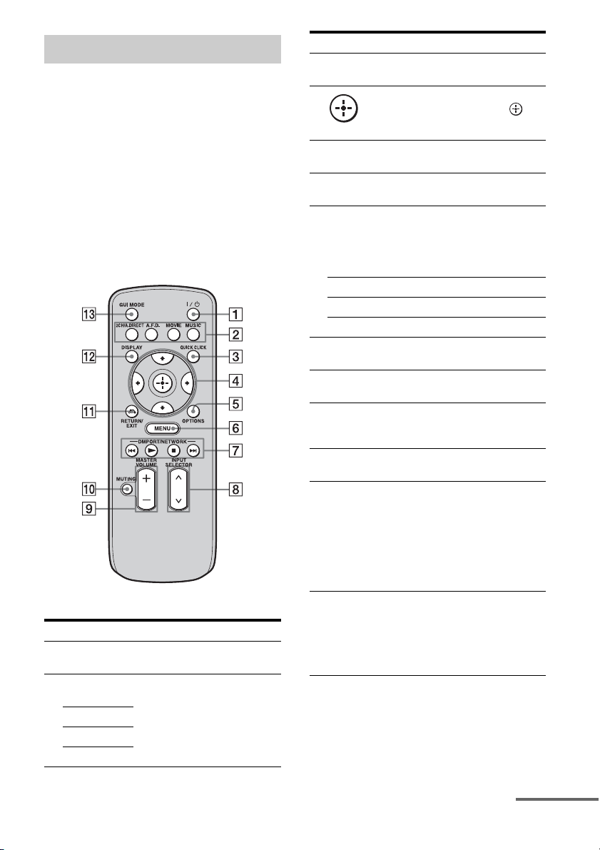
Remote commander
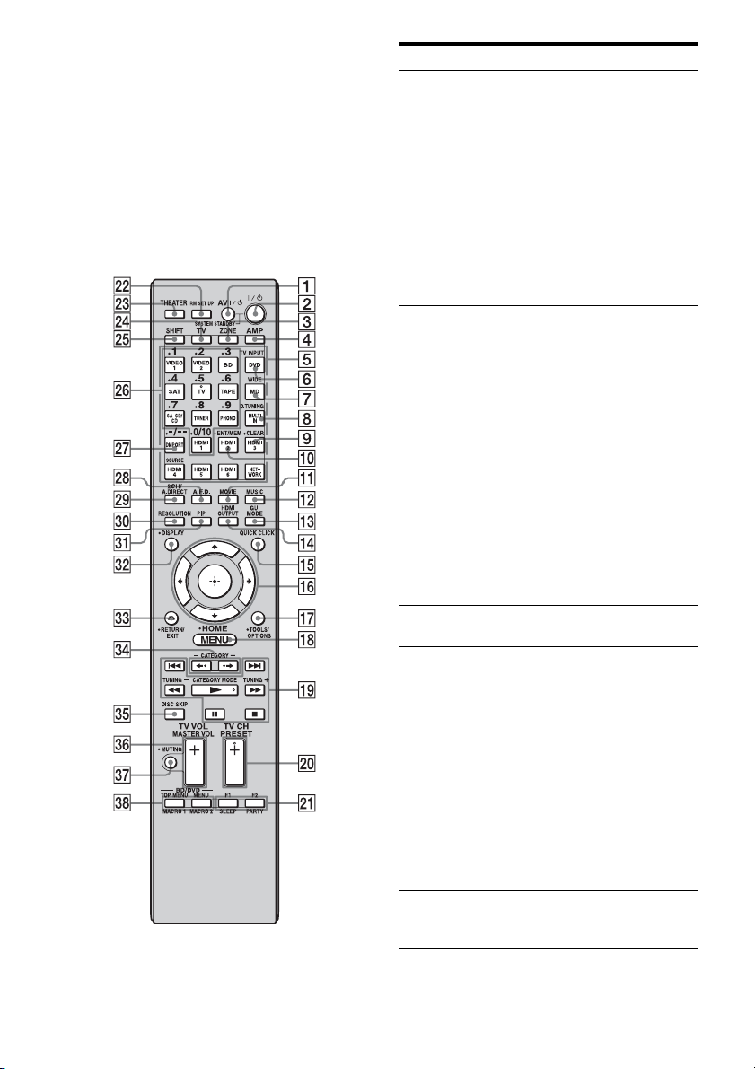
Name Function
A ?/1 (on/
standby)
Press to turn a receiver on or off.
B 2CH/
A.DIRECT
Press to select sound field
(page 82, 83, 86, 88).
A.F.D.
MOVIE
MUSIC
C QUICK
CLICK
Press to display the on-screen
remote on the TV screen.
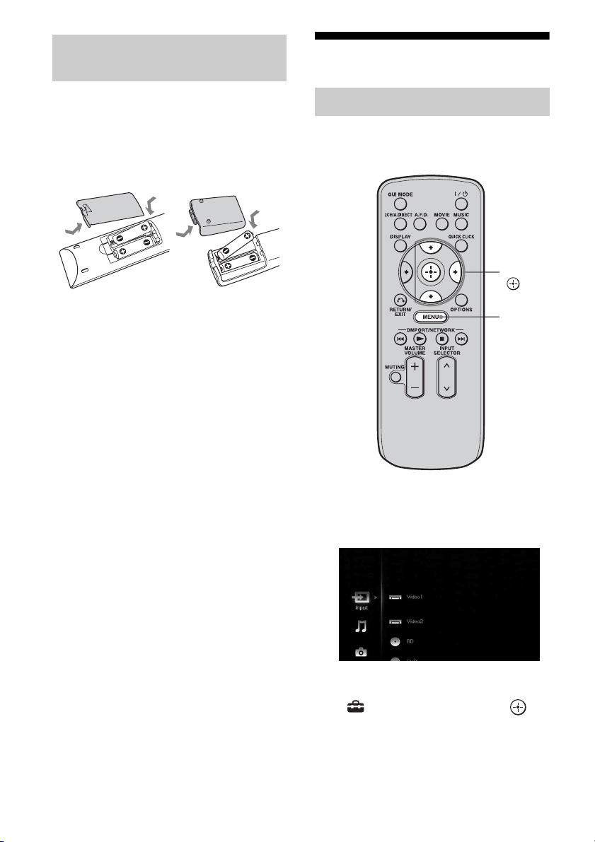
D
V/v/B/b
Press V/v/B/b to select the
menu item. Then press to
enter the selection.
E OPTIONS Press to display and select items
from option menus.
F MENU Press to display the menu to
operate the receiver.
G DMPORT/
NETWORK
Press to operate the component
connected to the DIGITAL
MEDIA PORT adapter
(page 64), or to play back
content on the server (page 97).
N Starts play.
x Stops play.
./> Skips tracks.
H INPUT
SELECTOR
Press to select the input source
to play back.
I MASTER
VOLUME +/–
Press to adjust the volume level.
J MUTING Press to turn off the sound
temporarily. Press the button
again to restore the sound.
K RETURN/
EXIT O
Press to return to the previous
menu or exit the menu.
L DISPLAY Press to display the current
status of or information on
components connected to the
receiver.
Note
In the GUI MODE, press the
button to display the menu on
the TV screen.
M GUI MODE Press to switch the display
mode of the menu between GUI
MODE (to display the menu on
the TV screen) and DISPLAY
MODE (to display the menu in
the display window).
Name Function
continued
18
GB
Multifunction remote
commander
(RM-AAL021/RM-AAL022)
The RM-AAL021 remote is supplied with the
European model only and RM-AAL022 is
supplied with the USA/Canadian model only.
The RM-AAL022 remote is used for
illustration purpose. Any differences in
operation are clearly indicated in the text, for
example, “USA/Canadian model only.”
Name Function
A AV ?/1 (on/
standby)
Press to turn on or off the audio/
video components that the
remote is assigned to operate
(page 172).
If you press ?/1 (2) button at
the same time, it will turn off
the receiver and other Sony
components (SYSTEM
STANDBY).
Note
The function of the AV ?/1
switch changes automatically
each time you press the input
button (5).
B ?/1 (on/
standby)
Press to turn the receiver on or
off.
If zone 2 or zone 3 is selected,
only the main receiver is turned
on or off with this button. To
turn off all components
including an amplifier in zone 2
or zone 3, press ?/1 and AV ?/
1 (1) at the same time
(SYSTEM STANDBY).
Saving the power in
standby mode.
When “Control for HDMI”
(page 142) and “Installer
Mode” (page 146) are set to
“OFF,” and the power for
zone 2/zone 3 is turned off.
C ZONE Press to switch the zone 2 or
zone 3 operation (page 105).
D AMP Press to enable the receiver
operation.
E Input
buttons
Press one of the buttons to
select the component you want
to use. When you press any of
the input buttons, the receiver
turns on. The buttons are
factory assigned to control Sony
components (page 62). You can
program the remote to control
non-Sony components
following the steps in
“Programming the remote”
(page 172).
F TV INPUT Press TV (wf), then press TV
INPUT to select the input signal
of a TV.
19
GB
G WIDE Press TV (wf), then press
WIDE repeatedly to select the
wide picture mode.
H D.TUNING Press SHIFT (wg), then press to
enter direct tuning mode
(page 69, 76).
I CLEAR Press SHIFT (wg), then press to
– clear a mistake when you
press the incorrect numeric
button.
– return to continuous
playback, etc. of the satellite
tuner or DVD player.
J ENT/MEM Press SHIFT (wg), then press
ENT/MEM to enter the value
after selecting a channel, disc,
or track using the numeric
buttons, or to store a station
during tuner operation.
K MOVIE Press to select sound field for
movies (page 88).
L MUSIC Press to select sound field for
music (page 86).
M GUI MODE Press to switch the display
mode of the menu between GUI
MODE (to display the menu on
the TV screen) and DISPLAY
MODE (to display the menu in
the display window).
N HDMI
OUTPUT
Press to select an HDMI jack
you want to output HDMI video
signals to (page 33).
O QUICK
CLICK
Press to display the on-screen
remote on the TV screen.
P
V/v/B/b
Press V/v/B/b to select the
menu items. Then press to
enter the selection.
Q TOOLS/
OPTIONS
Press to display and select items
from option menus for receiver,
DVD player, TV, or Blu-ray
Disc Player, etc.
R MENU
HOME
Press to display the menu used
to operate audio/video
components or a TV.
Name Function
S m/M
a)
x
a)
X
a)
N
a) b)
./>
a)
Press to operate the DVD
player, Blu-ray Disc Player, CD
player, MD deck, tape deck, or
component connected to the
DIGITAL MEDIA PORT
adapter etc.
CATEGORY
MODE
(USA/
Canadian
model only)
Press to select the category
mode for satellite tuner.
TUNING +/– Press to select station.
T PRESET
+
b)
/–
Press to register FM/AM/
satellite tuner stations or to
select preset stations.
TV CH +
b)
/– Press TV (wf), then press TV
CH +/– to operate the TV,
satellite tuner, VCR, etc.
U F1/F2 Press BD or DVD (5), then
press F1 or F2 to select a
component to operate.
• HDD/DISC combo
F1: HDD
F2: DVD disc, Blu-ray Disc
• DVD/VHS combo
F1: DVD disc, Blu-ray Disc
F2: VHS
PARTY Press to display confirmation
screen to start party mode
(page 110).
SLEEP Press AMP (4), then press
SLEEP to activate the sleep
timer function and the duration
which the receiver turns off
automatically (page 121).
V RM SET UP Press to set up the remote
(page 124).
W THEATER Press to turn the Theater mode
on and off when connecting the
receiver to products featuring
“BRAVIA” Sync.
X TV Press to enable the TV
operation.
Y SHIFT Press to light up the button. It
changes the remote button
function to activate the buttons
with pink printing.
Name Function
continued
20
GB
a)
See the table on page 171 for information on the
buttons that you can use to control each
component.
b)
The tactile dot is attached to these buttons (TV/5,
N, PRESET +/TV CH +). Use as a mark of
operation.
Notes
• Some functions explained in this section may not
work depending on the model.
• The above explanation is intended to serve as an
example only. Therefore, depending on the
component, the above operation may not be
possible or may operate differently than described.
Z Numeric
buttons
Press SHIFT (wg), then press to
– preset/tune to preset stations.
– select track numbers of the
CD player, DVD player,
Blu-ray Disc Player or MD
deck. Press -/-- (wj) to select
track number 10.
– select channel numbers of
the VCR or satellite tuner.
– After pressing TV (wf),
press the numeric buttons to
select the TV channels.
wj -/-- Press to
– select track numbers over 10
of the CD player, DVD
player, Blu-ray Disc Player,
or MD deck.
– select channel numbers over
10 of the TV, Satellite tuner
or the VCR.
wk A.F.D. Press to select sound field
(page 83).
wl 2CH/
A.DIRECT
Press to select sound field or to
switch the audio of the selected
input to analog signal without
any adjustment (page 82).
e;
RESOLUTION
Press RESOLUTION
repeatedly to change the
resolution of signals output
from the HDMI OUT or
COMPONENT VIDEO
MONITOR OUT jack.
ea PIP Press PIP to switch the image of
the PIP (Picture in Picture)
window. The image of the PIP
window is the one from the
EXT VIDEO IN jack. You can
swap the position of the main
screen and the PIP window by
pressing (qh).
Note
When the HDMI input is
selected on the main screen, you
cannot swap the position of the
main screen and the PIP window.
es DISPLAY Press to display the current
status of or information on
components connected to the
receiver.
Note
In the GUI MODE, press the
button to display the menu on
the TV screen.
Name Function
ed RETURN/
EXIT O
Press to return to the previous
menu or exit the menu while the
menu or on-screen guide of the
VCR, DVD player, or satellite
tuner is displayed on the TV
screen.
ef CATEGORY
+/–
(USA/
Canadian
model only)
Press to select the category for
satellite tuner.
B·/·b Press to select an album.
eg DISC SKIP Press to skip a disc when using
a multi-disc changer.
eh MASTER
VOL +/–
Press to adjust the volume level
of all speakers at the same time.
TV VOL +/– Press TV (wf), then press TV
VOL +/– to adjust the volume
level of the TV.
ej MUTING Press to turn off the sound
temporarily. Press the button
again to restore the sound.
ek BD/DVD/
TOP MENU,
MENU
Press to display the menus of
the DVD player on the TV
screen. Then use V/v/B/b and
to perform a menu
operations.
MACRO1,
MACRO2
Press AMP (4), then press
MACRO 1 or MACRO 2 to set
up the macro function
(page 175).
Name Function
21
GB
Getting Started
1: Installing speakers
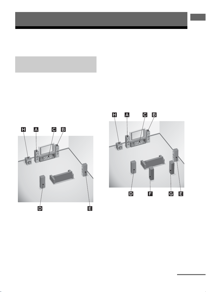
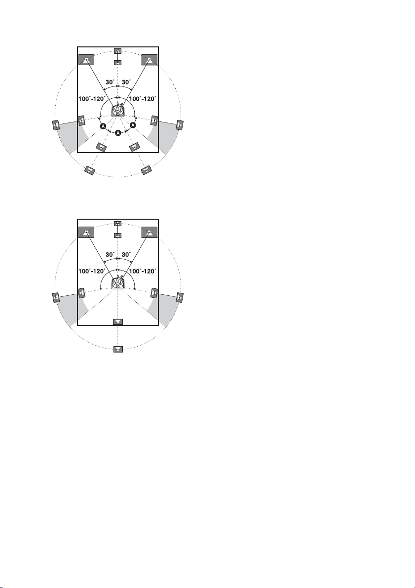
This receiver allows you to use a 7.1 channel system (7 speakers and one subwoofer).
To fully enjoy theater-like multi-channel
surround sound requires five speakers (two
front speakers, a center speaker, and two
surround speakers) and a subwoofer (5.1
channel system).
Example of a 5.1 channel
speaker system configuration
AFront left speaker
BFront right speaker
CCenter speaker
DSurround left speaker
ESurround right speaker
HSubwoofer
You can enjoy high fidelity reproduction of
DVD or Blu-ray Disc software recorded sound
in the Surround EX format if you connect one
additional surround back speaker (6.1 channel
system) or two surround back speakers (7.1
channel system)
.
Example of a 7.1 channel
speaker system configuration
AFront left speaker
BFront right speaker
CCenter speaker
DSurround left speaker
ESurround right speaker
FSurround back left speaker
GSurround back right speaker
HSubwoofer
Getting Started
Enjoying a 5.1/7.1 channel
system
continued
22
GB
Tips
•The angle A should be the same.
• When you connect a 6.1 channel speaker system,
place the surround back speaker behind the seating
position.
• Since the subwoofer does not emit highly
directional signals, you can place it wherever you
want.
23
GB
Getting Started
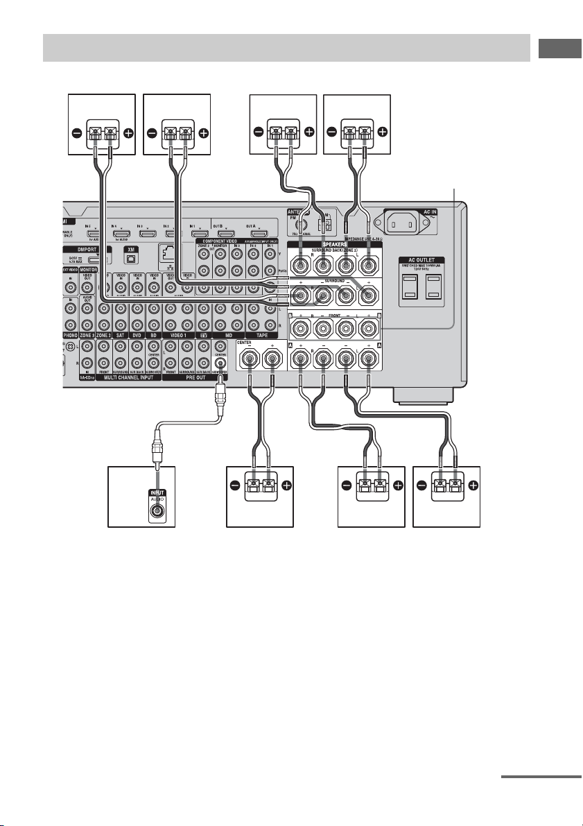
Before connecting cords, make sure to disconnect the AC power cord (mains lead).
AFront speaker A (L)
BFront speaker A (R)
CCenter speaker
DSubwoofer
b)
ESurround back speaker (L)
c)
FSurround back speaker (R)
c)
GSurround speaker (L)
HSurround speaker (R)
a)
If you have an additional front speaker
system, connect them to the FRONT
SPEAKERS B terminals. You can select
the front speaker system you want to use
with the SPEAKERS switch (OFF/A/B/
A+B) on the front panel (page 50).
Connecting speakers
HG F
BAD
E
C
A
B
FRONT SPEAKERS
B terminals
a)
A Monaural audio cord (not supplied)
B Speaker cords (not supplied)
BB
B
continued

24
GB
b)
When you connect a subwoofer with an auto
standby function, turn off the function when
watching movies. If the auto standby
function is set to on, it turns to standby mode
automatically based on the level of the input
signal to a subwoofer, then sound may not be
output.
c)
If you connect only one surround back
speaker, connect it to the SURROUND
BACK SPEAKERS L terminals.
Notes
• When you connect all the speakers with a nominal
impedance of 8 ohms or higher, set “Impedance” in
the Speaker settings menu to “8 Ω.” In other
connections, set it to “4 Ω.” For details, see “7:
Setting the speakers” (page 48).
• Before connecting the AC power cord (mains
lead), make sure that metallic wires of the speaker
cords are not touching each other between the
SPEAKERS terminals.
Tip
To connect certain speakers to another power
amplifier, use the PRE OUT jacks. The same signal
is output from both the SPEAKERS terminals and
the PRE OUT jacks. For example, if you want to
connect just the front speakers to another amplifier,
connect that amplifier to the PRE OUT FRONT L
and R jacks.
ZONE 2 connection
You can assign the SURROUND BACK
SPEAKERS terminals E and F to the
speakers of the zone 2. Set “Sur Back Assign”
to “ZONE2” in the Speaker settings menu.
See “Using Multi-zone Features” (page 105)
for details on connection and operation in zone
2.
25
GB
Getting Started
2: Connecting the monitor
You can watch the selected input image when you connect the HDMI OUT or MONITOR OUT
jacks to a TV. You can operate this receiver using a GUI (Graphical User Interface).
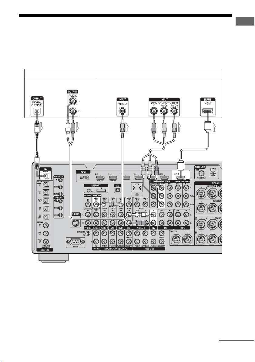
It is not necessary to connect all the cables. Connect audio and video cords according to the jacks
of your components.
TV monitor
AB
A Optical digital cord (not supplied)
B Audio cord (not supplied)
C Video cord (not supplied)
D Component video cord (not supplied)
E HDMI cable (not supplied)
Audio signals
CD E
Video signals
continued

26
GB
Notes
• Before connecting cords, make sure to disconnect
the AC power cord (mains lead).
• Connect image display components such as a TV
monitor or a projector to the MONITOR VIDEO
OUT jack on the receiver. You may not be able to
record, even if you connect recording components.
• Turn on the receiver when the video and audio of a
playback component are being output to a TV via
the receiver. If the power supply of the receiver is
not turned on, neither video nor audio is
transmitted.
• Depending on the status of the connection between
the TV and the antenna (aerial), the image on the
TV screen may be distorted. In this case, place the
antenna (aerial) farther away from the receiver.
Tips
• The receiver has a video conversion function. For
details, see “Notes on converting video signals”
(page 41).
• The sound of the TV is output from the speakers
connected to the receiver if you connect the audio
output jack of the TV and the TV IN jacks of the
receiver. In this configuration, set the sound output
jack of the TV to “Fixed” if it can be switched
between either “Fixed” or “Variable.”
• The screen saver is activated when the GUI menu
is displayed on the TV screen and there has been no
operation attempted for 15 minutes.

27
GB
Getting Started
3a: Connecting the audio components
This section describes how to hook up your
components to this receiver. Before you begin,
see “Component to be connected” below for
the pages which describe how to connect each
component.
After hooking up all your components,
proceed to “4: Connecting the antennas
(aerials)” (page 44).
How to hook up your
components
Component to be connected Page
Super Audio CD
player/ CD player
With digital audio
output
28
With multi-channel
audio output
30
With analog audio
output only
31
MD player With digital audio
output
28
With analog audio
output only
31
Tape deck, Analog disc turntable 31
28
GB
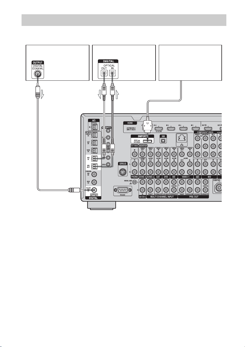
The following illustration shows how to connect a Super Audio CD player, CD player, an MD deck
and DIGITAL MEDIA PORT adapter.
Notes
• When connecting optical digital cords, insert the
plugs straight in until they click into place.
• Do not bend or tie optical digital cords.
• Before connecting cords, make sure to disconnect
the AC power cord (mains lead).
• To disconnect the DIGITAL MEDIA PORT
adapter, observe the following precautions.
– Remove the DIGITAL MEDIA PORT adapter
after removing the cord when cords are
connected to the COMPONENT VIDEO jack.
– Remove the DIGITAL MEDIA PORT adapter
by squeezing the sides of the connector, since
the connector is locked in place.
Tip
All the digital audio jacks are compatible with
32 kHz, 44.1 kHz, 48 kHz, 88.2 kHz and 96 kHz
sampling frequencies.
Connecting components with digital audio input/output jacks
Super Audio CD
player, CD player
DIGITAL MEDIA PORT
adapter
A
A Coaxial digital cord (not supplied)
B Optical digital cord (not supplied)
B
MD deck

29
GB
Getting Started
Notes on playing a Super Audio
CD on a Super Audio CD player
• No sound is output when playing a Super
Audio CD on a Super Audio CD player
connected to only the COAXIAL SA-CD/
CD IN jack on this receiver. When you play
a Super Audio CD, connect the player to the
MULTI CHANNEL INPUT or SA-CD/CD
IN jacks. Refer to the operating instructions
supplied with the Super Audio CD player.
• Connect a player which can output DSD
signals from the HDMI jack to the receiver
using an HDMI cable.
• You cannot make digital recordings of a
Super Audio CD.
If you want to connect several
digital components, but cannot
find an unused input
See “Enjoying the sound/images from other
inputs (Input Assign)” (page 119).
30
GB
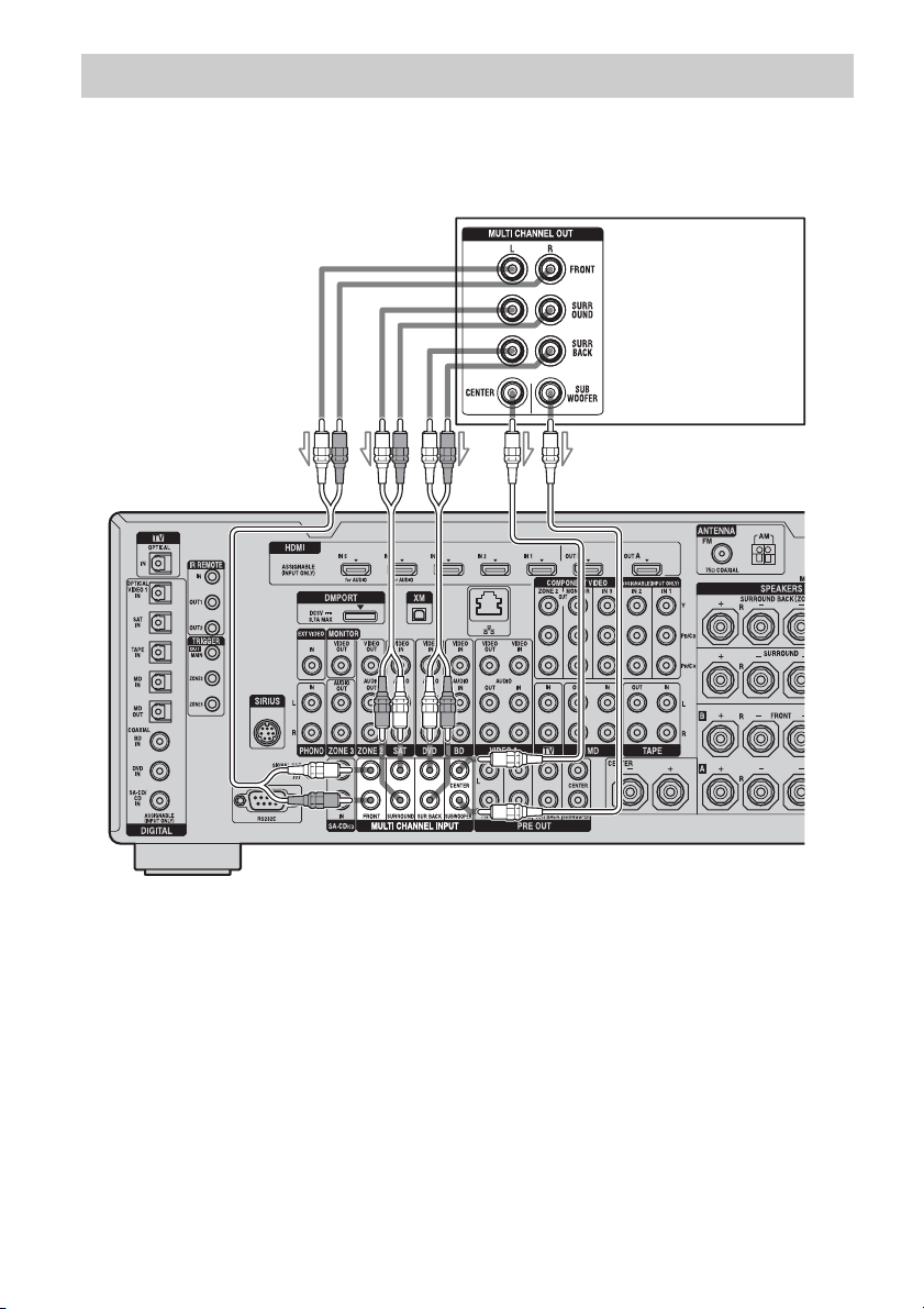
If your DVD player, Blu-ray Disc Player or Super Audio CD player is equipped with multi-channel
output jacks, you can connect them to the MULTI CHANNEL INPUT jacks of this receiver to
enjoy multi-channel sound. Alternatively, the multi-channel input jacks can be used to connect an
external multi-channel decoder.
Notes
• Before connecting cords, make sure to disconnect
the AC power cord (mains lead).
• DVD player, Blu-ray Disc Player and Super Audio
CD players may not have the SURROUND BACK
jacks.
• When “Sur Back Assign” is set to “BI-AMP” or
“ZONE2” in the Speaker settings menu, the input
to the SUR BACK jacks is invalid.
• Audio input signals from MULTI CHANNEL
INPUT jacks are not output to any audio output
jacks. The signals cannot be recorded.
Connecting components with multi-channel output jacks
DVD player,
Blu-ray Disc Player,
Super Audio CD player,
etc.
A
B
A Audio cord (not supplied)
B Monaural audio cord (not supplied)
31
GB
Getting Started
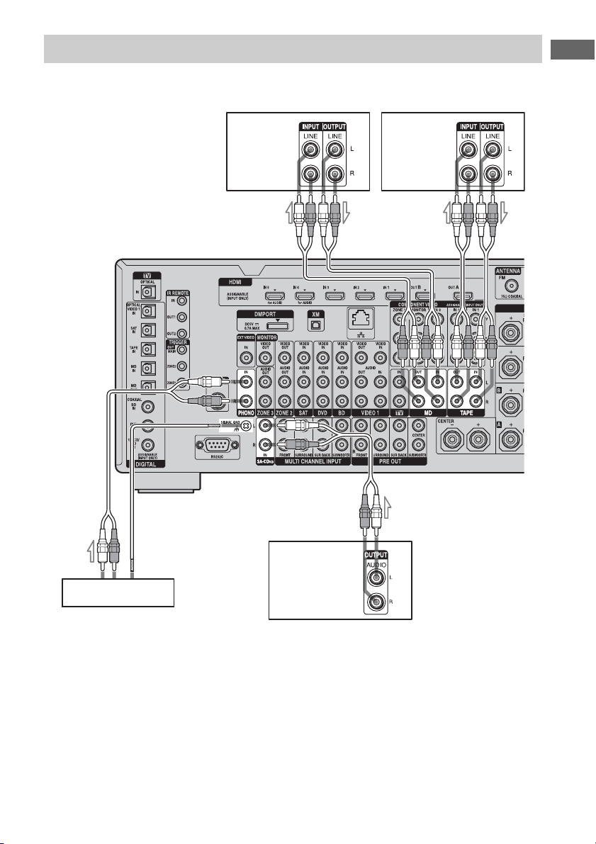
The following illustration shows how to connect a component with analog jacks, such as Super
Audio CD, CD player, MD deck, tape deck and turntable, etc.
Notes
• If your turntable has a ground (earth) wire, connect
it to the (U) SIGNAL GND terminal.
• Before connecting cords, make sure to disconnect
the AC power cord (mains lead).
Connecting components with analog audio jacks
Super Audio CD
player, CD player
Tur ntable
A
Tape deck
A Audio cord (not supplied)
A
A
MD deck
A
32
GB
3b: Connecting the video components
This section describes how to hook up your
components to this receiver. Before you begin,
see “Component to be connected” below for
the pages which describe how to connect each
component.
After hooking up all your components,
proceed to “4: Connecting the antennas
(aerials)” (page 44).
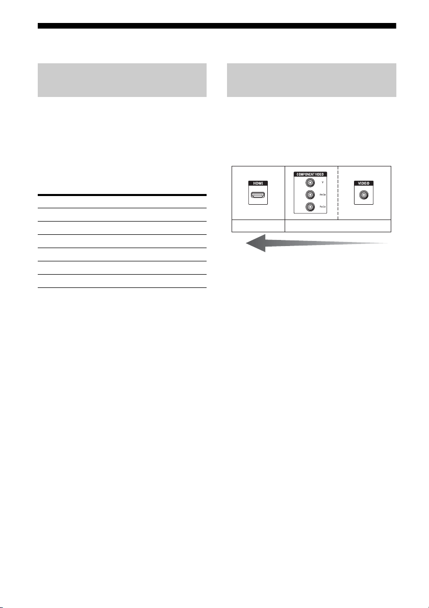
The image quality depends on the connecting
jack. See the illustration that follows. Select
the connection according to the jacks on your
components.
How to hook up your
components
Component to be connected Page
TV monitor 25
With HDMI jack 33
DVD player, Blu-ray Disc Player 37
Satellite tuner, Set-top box 38
DVD recorder, VCR 39
Camcorder, video game, etc. 39
Video input/output jacks to be
connected
High quality image
Digital Analog

33
GB
Getting Started
HDMI is the abbreviated name for High-
Definition Multimedia Interface. It is an
interface which transmits video and audio
signals in digital format.
HDMI features
• A digital audio signals transmitted by HDMI
can be output from the speakers and the PRE
OUT jacks on this receiver. This signal
supports Dolby Digital, DTS, DSD, and
Linear PCM.
• Linear PCM (sampling frequency less than
192 kHz) with digital audio signals of up to
8 channels can be received with this receiver
using the HDMI IN jack.
• Analog video signals input to the VIDEO
jack, or COMPONENT VIDEO jacks can be
output as HDMI signals. Audio signals are
not output from HDMI OUT jacks when the
image is converted.
• This receiver supports DSD transmission
(Super Audio CD), extended by HDMI
ver1.2.
• This receiver supports High Bitrate Audio
(DTS-HD Master Audio, Dolby TrueHD),
Deep Color and x.v.Color (x.v.Colour)
transmission, extended by HDMI ver1.3.
• The HDMI jacks of this receiver support the
Control for HDMI function. The HDMI
OUT B jack, however, does not support the
Control for HDMI function.
• HDMI IN 4 and IN 5 are inputs which are
considered sound quality. Input IN 4 or IN 5
when you need higher quality sound. You
can also use IN 4 or IN 5 jacks in the same
manner as the HDMI IN 3.
• The HDMI IN 1, IN 2, and IN 6 jacks are
used for connecting a camcorder. Use the
HDMI IN 1, IN 2, and IN 6 jacks when you
connect a camcorder to the receiver.
Connecting components with
HDMI jacks
continued
34
GB
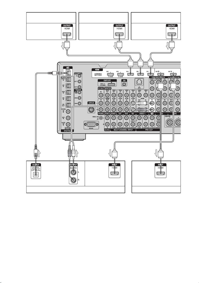
DVD player Satellite tuner/Set-top box
Blu-ray Disc Player, PS3™,
hard disk recorder
A
Audio/video
signals
Audio/video
signals
Audio/video
signals
TV monitor, projector, etc.
Audio
signals
AA
A
Audio/
video
signals
To TV OPTICAL
IN jacks
CB
Projector, etc.
Audio/
video
signals
A
A HDMI cable (not supplied)
We recommend that you use a Sony HDMI cable.
B Optical digital cord (not supplied)
C Audio cord (not supplied)
35
GB
Getting Started
To enjoy TV multi channel
surround sound broadcasting
You can listen to TV multi channel surround
sound broadcasting from the speakers
connected to the receiver.
Connect the OPTICAL output jack of the TV
to the OPTICAL IN jack of the receiver.
Tips
• Connect to at least one of the audio cords (B or
C).
• You can watch the image of the camcorder easily
with connecting your camcorder to the HDMI
IN 1, IN 2, and IN 6 jacks (page 114).
A
Camcorder
Audio/video signals
A HDMI cable (not supplied)
We recommend that you use a Sony HDMI cable.
continued

36
GB
Notes on connecting cables
• Use a High Speed HDMI cable. If you use a
Standard HDMI cable, 1080p or Deep Color
images may not be displayed properly.
• Sony recommends that you use an HDMI-
authorized cable or Sony HDMI cable.
• We do not recommend using an HDMI-DVI
conversion cable. When you connect an
HDMI-DVI conversion cable to a DVI-D
component, the sound and/or the image may
not be output. Connect other audio cords or
digital connecting cords, then set “Input
Assign” in the Input Option menu when the
sound is not output correctly.
• Before connecting cables, make sure to
disconnect the AC power cord (mains lead).
Notes on HDMI connections
• Check the setup of the connected component
if an image is poor or the sound does not
come out of a component connected via the
HDMI cable.
• An audio signal input to the HDMI IN jack
is output from the speaker output jacks,
PHONES jack, HDMI OUT jack and PRE
OUT jacks. It is not output from any other
audio jacks.
• A video signal input to the HDMI IN jack
can only be output from the HDMI OUT
jack. The video input cannot be output from
the VIDEO OUT jacks or MONITOR
VIDEO OUT jacks.
• When you want to listen to the sound from
the TV speaker, set “Audio Out” to
“TV+AMP” in the HDMI settings menu. If
set to “AMP,” the sound is not output from
the TV speaker.
• Be sure to turn on the receiver when video
and audio signals of a playback component
are being output to a TV through this
receiver. If you set “Pass Through” to
“OFF,” unless the power is on, neither video
nor audio signals will be transmitted.
• Audio signals (sampling frequency, bit
length, etc.) transmitted from an HDMI jack
may be suppressed by the connected
component. Check the setup of the
connected component if an image is poor or
the sound does not come out of a component
connected via the HDMI cable.
• Sound may be interrupted when the
sampling frequency, the number of channels
or audio format of audio output signals from
the playback component is switched.
• When the connected component is not
compatible with copyright protection
technology (HDCP), the image and/or the
sound from the HDMI OUT jack may be
distorted or may not be output.
In this case, check the specification of the
connected component.
• Refer to the operating instructions of each
component connected for details.
• Set the image resolution of the player to
more than 720p/1080i to enjoy High Bitrate
Audio (DTS-HD Master Audio, Dolby
TrueHD).
• The image resolution of player may need
certain settings be made before you can
enjoy DSD and multi-channel Linear PCM.
Refer to the operating instructions of the
player.
• Not every HDMI component supports all
functions that are defined by the specified
HDMI version. For example, components
that support HDMI, ver. 1.3a, may not
support Deep Color.
37
GB
Getting Started
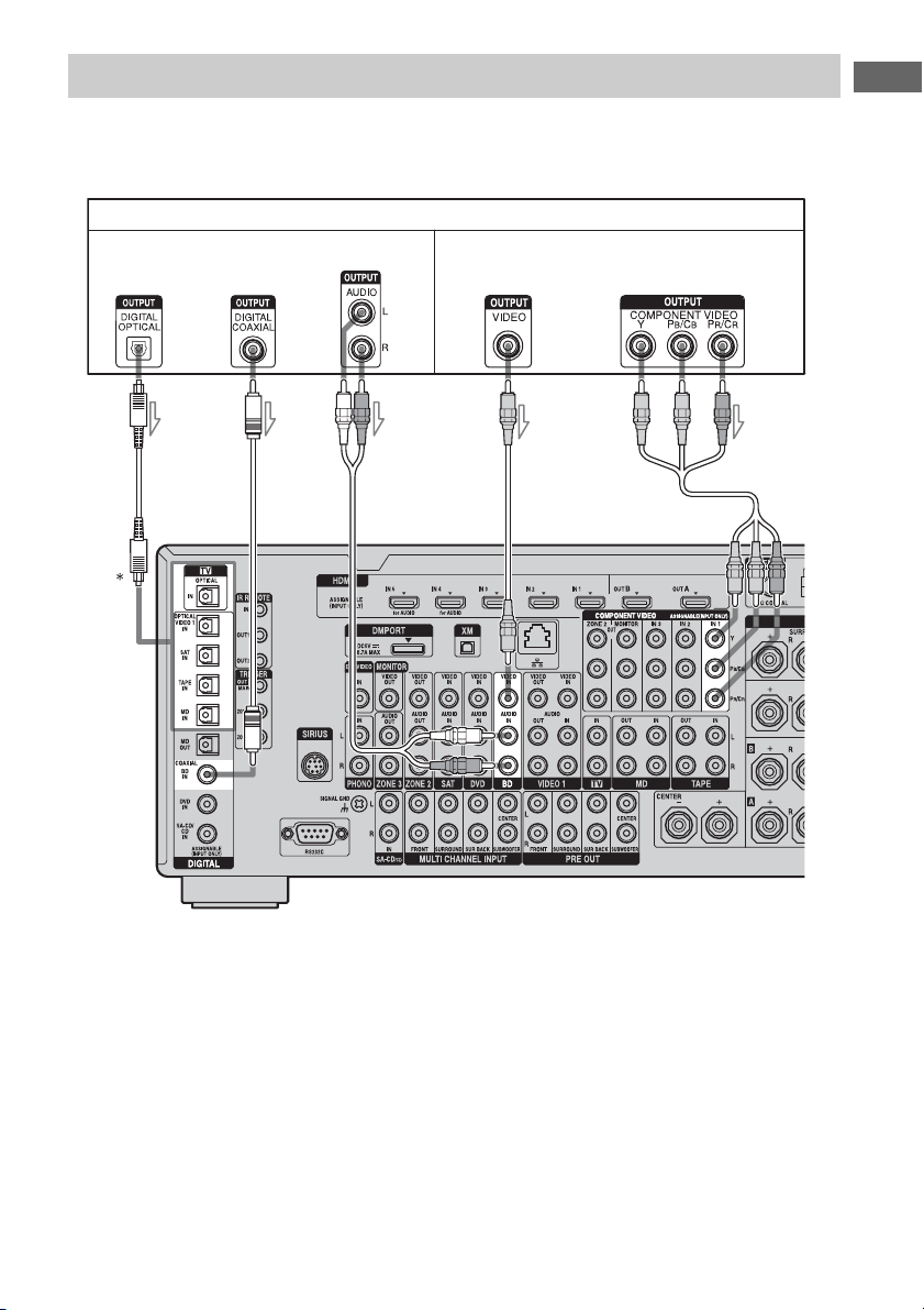
The following illustration shows how to connect a DVD player, Blu-ray Disc Player.
It is not necessary to connect all the cables. Connect audio and video cords according to the jacks
of your components.
* When you connect a component equipped with an
OPTICAL jack, set “Input Assign” in the Input
menu.
Notes
• To output multi-channel digital audio, set the
digital audio output setting on the DVD player,
Blu-ray Disc Player. Refer to the operating
instructions supplied with the DVD player, Blu-ray
Disc Player.
• Before connecting cords, make sure to disconnect
the AC power cord (mains lead).
Connecting a DVD player, Blu-ray Disc Player
DVD player, Blu-ray Disc Player
ABC
A Optical digital cord (not supplied)
B Coaxial digital cord (not supplied)
C Audio cord (not supplied)
D Video cord (not supplied)
E Component video cord (not supplied)
D
Audio signals Video signals
E
38
GB
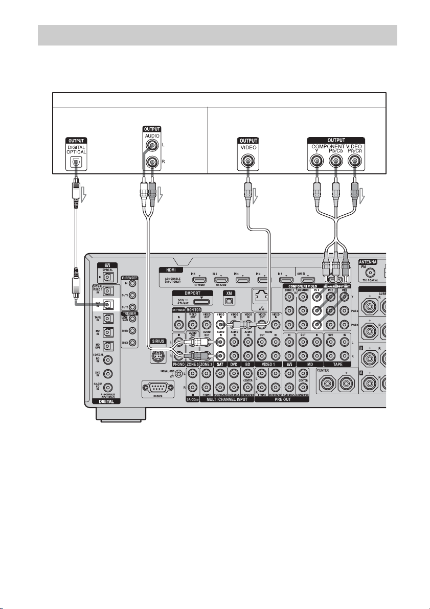
The following illustration shows how to connect a satellite tuner, Set-top box.
It is not necessary to connect all the cables. Connect audio and video cords according to the jacks
of your components.
Note
Before connecting cords, make sure to disconnect
the AC power cord (mains lead).
Connecting a satellite tuner, Set-top box
Satellite tuner, Set-top box
AB C D
A Optical digital cord (not supplied)
B Audio cord (not supplied)
C Video cord (not supplied)
D Component video cord (not supplied)
Audio signals Video signals
39
GB
Getting Started
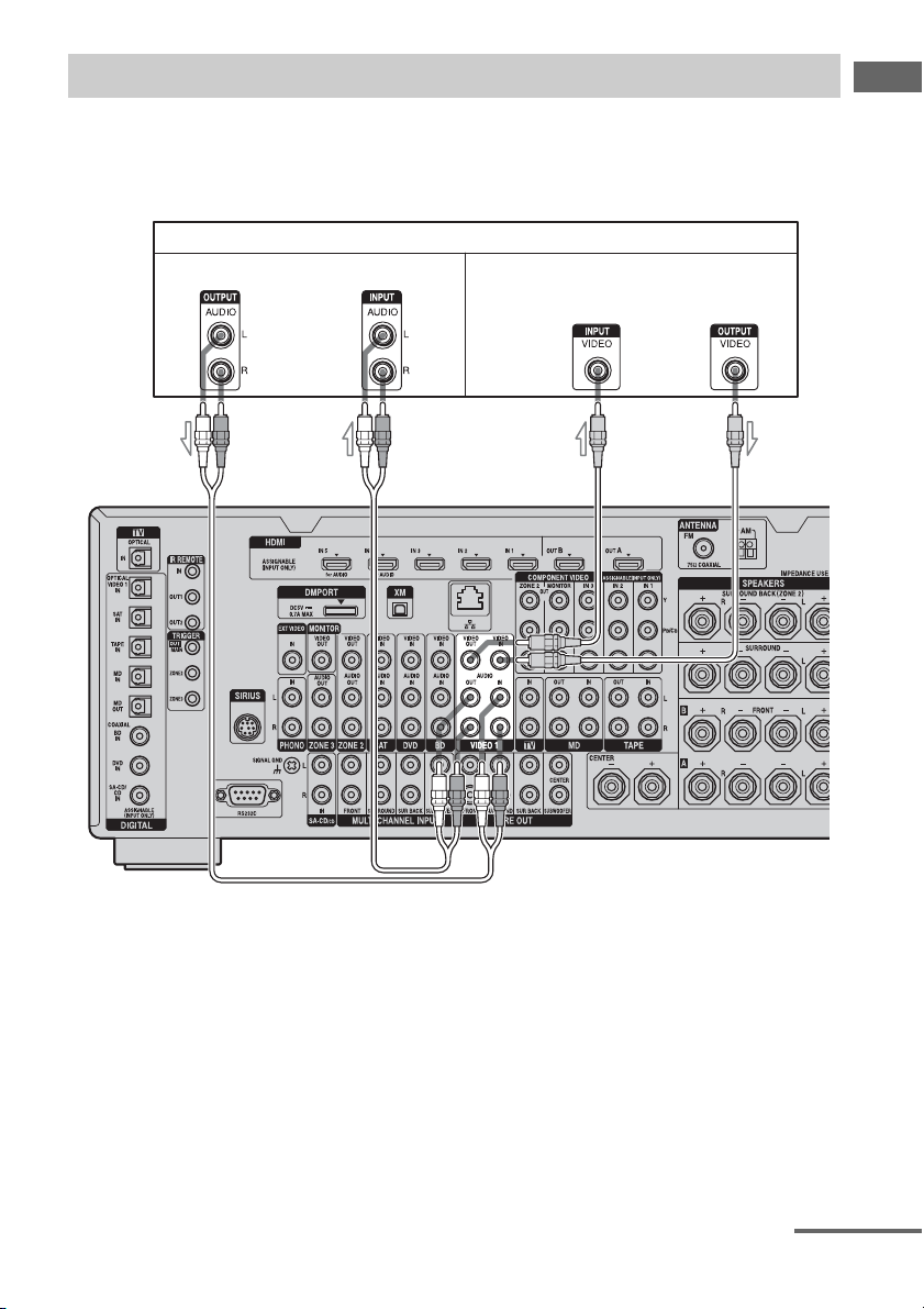
The following illustration shows how to connect a component which has analog jacks such as a
DVD recorder or VCR, etc.
It is not necessary to connect all the cables. Connect audio and video cords according to the jacks
of your components.
Connecting components with analog video and audio jack
DVD recorder, VCR
AB
Audio signals Video signals
A Audio cord (not supplied)
B Video cord (not supplied)
continued
40
GB
Function for conversion of video signals
This receiver is equipped with a function for converting video signals.
• Composite video signals can be output as HDMI video and component video signals.
• Component video signals can be output as HDMI video and video signals.
As the initial setting, video signals input from the connected component are output to the HDMI
OUT or MONITOR OUT jacks as shown in the table below.
We recommend you set the video conversion function to match the resolution of the monitor you
are using.
For details on the video converting function, see “ Video settings” (page 140).
a : Video signals are output.
– : Video signals are not output.
To the VIDEO 2 IN jacks
C Audio/video cord (not supplied)
Camcorder,
video game
Note
Before connecting cords, make sure to disconnect
the AC power cord (mains lead).
C
HDMI OUT A/B
COMPONENT VIDEO
MONITOR OUT
MONITOR VIDEO OUT
HDMI IN 1/2/3/4/5/6 a ––
VIDEO IN aa a
COMPONENT VIDEO IN aa a
INPUT jack
OUTPUT jack

41
GB
Getting Started
Notes on converting video
signals
• When video signals from a VCR, etc., are
converted on this receiver and then output to
your TV, depending on the status of the
video signal output, the image on the TV
screen may appear distorted horizontally or
no image may be output.
• HDMI video signals cannot be converted to
component video signals and video signals.
• The converted video signals are not output
from the VIDEO OUT jack.
• When you play a VCR with an image
improvement circuit, such as TBC, the
images may be distorted or may not be
output. In this case, set the image
improvement circuit function to off.
• The resolution of the signals output to the
COMPONENT VIDEO MONITOR OUT
jacks is converted up to 1080i. The
resolution of the signals output to the HDMI
OUT jacks are converted up to 1080p.
• COMPONENT VIDEO MONITOR OUT
jacks have restrictions on resolution when
the resolution of video signals protected by
copyright technology is converted.
Resolution of up to 480p can be output to the
COMPONENT VIDEO MONITOR OUT
jacks. The HDMI OUT jacks have no
restriction on resolution.
• Video signals for which the resolution has
been converted cannot be output from either
the COMPONENT VIDEO MONITOR
OUT jacks or the HDMI OUT jacks. The
video signals are output from the HDMI
OUT jacks when both are connected.
• Set “Resolution” to “AUTO” or “480i/576i”
in the Video settings menu to output the
video signals from the MONITOR VIDEO
OUT, COMPONENT VIDEO MONITOR
OUT jacks when both are connected.
To display Closed Caption
Set “Resolution” to “DIRECT” in the Video
settings menu when receiving a signal that
supports Closed Captions.
Use the same kind of cords for the input/output
signals.
To connect a recording
component
When recording, connect the recording
component to the VIDEO OUT jacks of the
receiver. Connect cords for input and output
signals to the same type of jack, as VIDEO
OUT jacks do not have an up-conversion
function.
Note
Signals output from the HDMI OUT or MONITOR
OUT jacks may not be recorded properly.
42
GB
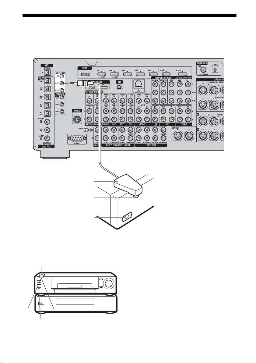
3c: Connecting the IR Blaster
Attach the supplied IR Blaster to components connected to the receiver. You can control
components connected to the receiver via the IR Blaster using the on-screen remote control.
Place the components and the IR Blaster as
follows when you want to operate two
components with the IR Blaster.
If the infrared receivers on the two
components do not line up as shown in the
illustration on the left, you must purchase an
optional IR Blaster (VM-50, not supplied) and
install it.
Note
For details on how to set up a component, refer to the
operating instructions of the component.
Tip
If the IR Blaster cable is too short, use a 3.5 mm jack
extension cable (not supplied).
IR Blaster
(supplied)
Infrared transmitter
Remote sensor
IR Blaster
Remote sensors

43
GB
Getting Started
After referring to the operating instructions of
the components connected to the receiver,
make sure to place the IR Blaster just above or
below the remote sensor. Remote sensors on
Sony Recorders and other products are
identified by the symbol.
Note
Do not remove the backing paper from the IR
Blaster yet.
After configuring the settings, remove the backing
paper from the IR Blaster and fix it in place.
44
GB
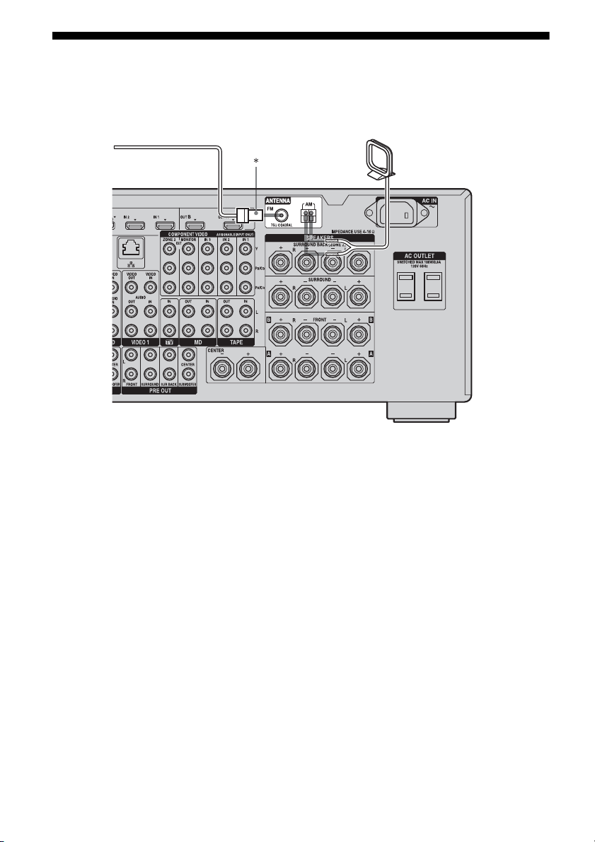
4: Connecting the antennas (aerials)
Connect the supplied AM loop antenna (aerial) and FM wire antenna (aerial).
* The shape of the connector varies depending on
the area.
Notes
• To prevent noise pickup, keep the AM loop antenna
(aerial) away from the receiver and other
components.
• Be sure to fully extend the FM wire antenna
(aerial).
• After connecting the FM wire antenna (aerial),
keep it as horizontal as possible.
• Before connecting cords, make sure to disconnect
the AC power cord (mains lead).
FM wire antenna (aerial) (supplied)
AM loop antenna (aerial)
(supplied)

45
GB
Getting Started
5: Connecting to the
network
Configuring your home network with DLNA-
compliant devices.
If your computer is connected to the Internet,
you can connect this receiver to the Internet as
well, through the wired LAN connection.
Note
The method used to connect your computer to the
Internet depends on the devices, your ISP, your
computer, and the router used.
The following system environment is required
to use the network function of the receiver.
A Broadband line connection
A Broadband line connection to the Internet is
required in order to listen to Rhapsody
®
or
SHOUTcast and to use the firmware update
function of the receiver. Rhapsody is only
available in the US.
Modem
This is the device that is connected to the
broadband line to communicate with the
Internet. Some of these devices are integrated
with the router.
Router
• Use a router compatible with 100 Mbps or
greater transmission speeds to enjoy content
on your home network.
• We recommend that you use a router
equipped with the built-in DHCP (Dynamic
Host Configuration Protocol) server.
This function automatically assigns IP
addresses on the LAN.
LAN cable (CAT-5)
• We recommend that you use this type of
cable for a wired LAN.
Some flat-type LAN cables are easily
affected by noise. We recommend that you
use normal-type cables.
• If the receiver is used in an environment in
which there is power supply noise from
electric products or in a noisy network
environment, use a shielded-type LAN
cable.
System requirements
46
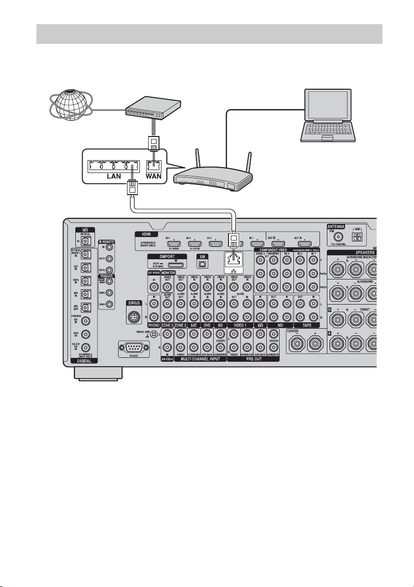
GB
The following illustration is a configuration example of a home network with the receiver, a
computer.
We recommend that you use a wired connection.
Note
A audio or video playback on the computer may
occasionally be interrupted when you use a wireless
connection.
Configuration example
Internet Modem
Computer
Router
LAN cable
(not supplied)
LAN cable
(not supplied)
47
GB
Getting Started
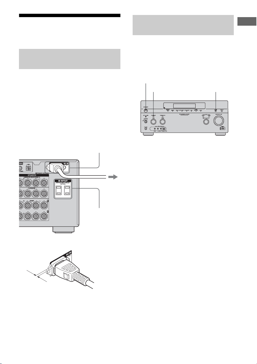
6: Preparing the receiver
and the remote
Connect the supplied AC power cord (mains
lead) to the AC IN terminal on the receiver,
then connect the AC power cord (mains lead)
to a wall outlet.
Notes
• Before connecting the AC power cord (mains
lead), make sure that metallic wires of the speaker
cords are not touching each other between the
SPEAKERS terminals.
• Connect the AC power cord (mains lead) firmly.
A several space is left between the plug and the
rear panel even when the power cord (mains
lead) is inserted firmly. The cord is supposed
be connected this way. This is not malfunction.
Before using the receiver for the first time,
initialize the receiver by performing the
following procedure. This procedure can also
be used to return settings you have made to
their factory defaults.
1 Press POWER to turn off the
receiver.
2 Hold down POWER while
pressing TONE MODE and
HDMI IN to turn on the receiver.
3 Release the TONE MODE and
HDMI IN after a few seconds.
After “MEMORY CLEARING...”
appears on the display for a while,
“MEMORY CLEARED.” appears.
All the settings you have changed or
adjusted are reset to the initial settings.
Note
It takes about 30 seconds for the memory to be
cleared completely. Do not turn the receiver off until
“MEMORY CLEARED.” appears on the display.
Connecting the AC power cord
(mains lead)
AC IN terminal
To the wall outlet
AC OUTLET
(USA/Canadian
model only)
AC power cord
(mains lead)
(supplied)
Performing initial setup
operations
POWER
TONE MODE HDMI IN
48
GB
Insert two R6 (size-AA) batteries in the RM-
AAL021 or RM-AAL022 remote commander.
Insert two R6 (size-AA) batteries in the RM-
AAU061 remote control.
Observe the correct polarity when installing
batteries.
Notes
• Do not leave the remote in an extremely hot or
humid place.
• Do not use a new battery with old ones.
• Do not mix manganese batteries and other kinds of
batteries.
• Do not expose the remote sensor to direct sunlight
or lighting apparatuses. Doing so may cause a
malfunction.
• If you do not intend to use the remote for an
extended period of time, remove the batteries to
avoid possible damage from battery leakage and
corrosion.
• When you replace the batteries, the programmed
remote codes may be cleared. If this happens,
program the remote codes again (page 172).
Tip
When the remote no longer operates the receiver,
replace all the batteries with new ones.
7: Setting the speakers
Set the appropriate speaker impedance for the
speakers you are using.
1 Press MENU.
The menu is displayed on the TV screen.
2 Press V/v repeatedly to select
“ Settings,” then press or
b.
The Settings menu list appears on the TV
screen.
Inserting batteries into the
remote
RM-AAL021
RM-AAL022
RM-AAU061
Setting the speaker impedances
V/v/b,
MENU
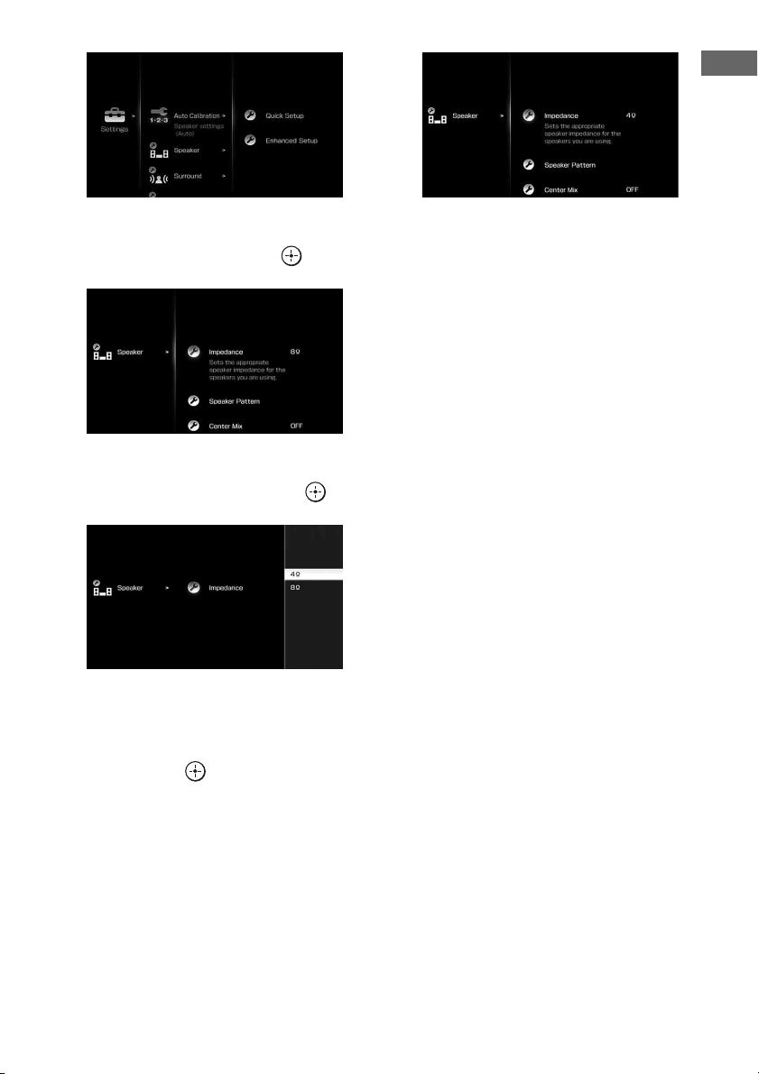
49
GB
Getting Started
3 Press V/v repeatedly to select
“Speaker,” then press or b.
4 Press V/v repeatedly to select
“Impedance,” then press .
5 Press V/v repeatedly to select
“4 Ω” or “8 Ω” depending on
the speakers you are using,
then press .
The parameter you have selected is
entered.
To exit the menu
Press MENU.
Notes
• If you are not sure of the impedances of the
speakers, refer to the operating instructions
supplied with your speakers. (This information is
often on the back of the speaker.)
• When you connect all speakers with a normal
impedance of 8 ohms or higher, set “Impedance” to
“8 Ω.” When connecting other types of speakers,
set it to “4 Ω.”
• When you connect front speakers to both the
SPEAKERS A and B terminals, connect the
speakers with a normal impedance of 8 ohms or
higher.
– When you connect speakers with impedance of
16 ohms or higher in both “A” and “B”
configuration:
Set “Impedance” to “8 Ω” in the Speaker
settings menu.
– For other types of speakers in other
configurations:
Set “Impedance” to “4 Ω” in the Speaker
settings menu.
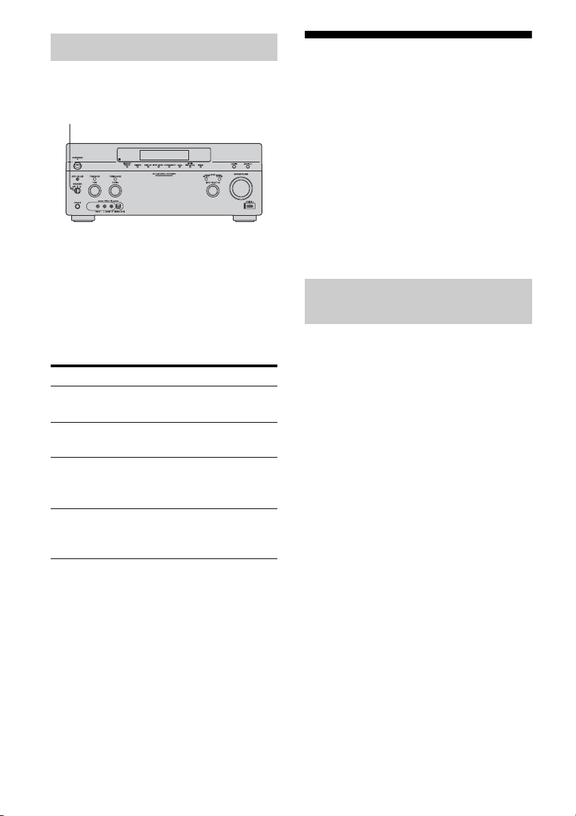
50
GB
You can select the front speakers you want to
drive.
Set the SPEAKERS switch to select
the front speaker system you want
to drive.
Note
This setting is not available when headphones are
connected.
8: Calibrating the
appropriate speaker
settings automatically
(Auto Calibration)
The DCAC (Digital Cinema Auto Calibration)
function allows you to perform automatic
calibration, such as checking the connection
between each speaker and the receiver,
adjusting the speaker level, and measuring the
distance of each speaker from your seating
position automatically.
Before you perform the auto calibration, set up
and connect the speakers (page 21-24).
• The AUTO CAL MIC jack is used for the
supplied optimizer microphone only. Do not
connect other microphones. Doing so may
damage the receiver and the microphone.
• During the measurement, the sound that
comes out of the speakers is very loud. The
volume of the sound cannot be adjusted. Pay
attention to the presence of children or to the
effect on your neighborhood.
• Perform the measurement in a quiet
environment to avoid the effect of noise and
get a more accurate measurement.
• If there are any obstacles in the path between
the optimizer microphone and the speakers,
the calibration cannot be performed
correctly. Remove any obstacle from the
measurement area to avoid measurement
error.
• When you use a bi-amplifier connection, set
“Sur Back Assign” to “BI-AMP” in the
Speaker settings menu before you perform
auto calibration.
Notes
• The auto calibration function does not work if
headphones are connected.
• Cancel MUTING if it is set to on.
Selecting the front speakers
Set to To select
A The speakers connected to the
FRONT SPEAKERS A terminals.
B The speakers connected to the
FRONT SPEAKERS B terminals.
A+B The speakers connected to both the
FRONT SPEAKERS A and B
terminals (parallel connection).
OFF No audio signals are output from
any speaker terminals, or the PRE
OUT jacks.
SPEAKERS switch
Before you perform the auto
calibration
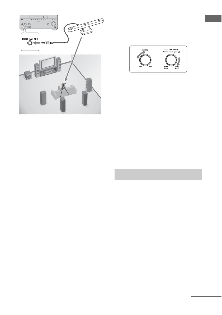
51
GB
Getting Started
1 Connect the supplied optimizer
microphone to the AUTO CAL
MIC jack.
2 Set up the optimizer
microphone.
Place the optimizer microphone at your
seating position. Use a stool or tripod so
that the optimizer microphone remains at
the same height as your ears. Orient the L
end of the optimizer microphone toward
the front left speaker and the R end of the
optimizer microphone toward the front
right speaker.
Note
When you position the optimizer microphone
at the center of the two speakers, if the angle
between the two speakers is too narrow, the
optimizer microphone cannot measure the left
and right speakers properly.
On setting up the active
subwoofer
• When a subwoofer is connected, turn on the
subwoofer and turn up the volume
beforehand. Turn the MASTER VOLUME
knob to just before the mid-point.
• If you connect a subwoofer with the
crossover frequency function, set the value
to maximum.
• If you connect a subwoofer with an auto
standby function, set it to off (deactivated).
Note
Depending on the characteristics of the subwoofer
you are using, the setup distance value may be
further away from the actual position.
To use the receiver as a pre-
amplifier
You can use the auto calibration function when
you use the receiver as a pre-amplifier.
In this case, the distance value shown on the
display may differ from the actual distance
value. However, there will be no problems
even if you continue to use the receiver with
that value.
The auto calibration function allows you to
measure the following:
• Speaker connections
a)
• Polarity of speakers
• Speaker distance
b)
• Speaker size
b)
• Speaker level
• Frequency characteristics
b) c)
a) This receiver corrects signals by analog
downmix processing only for the center speaker
and subwoofer when the multi-channel input is
selected. The correction is invalid for other
speakers.
b) The measurement result is not utilized in the
following cases.
– The multi-channel input is selected.
– “2ch Analog Direct” is being used.
Optimizer microphone
Performing auto calibration
continued
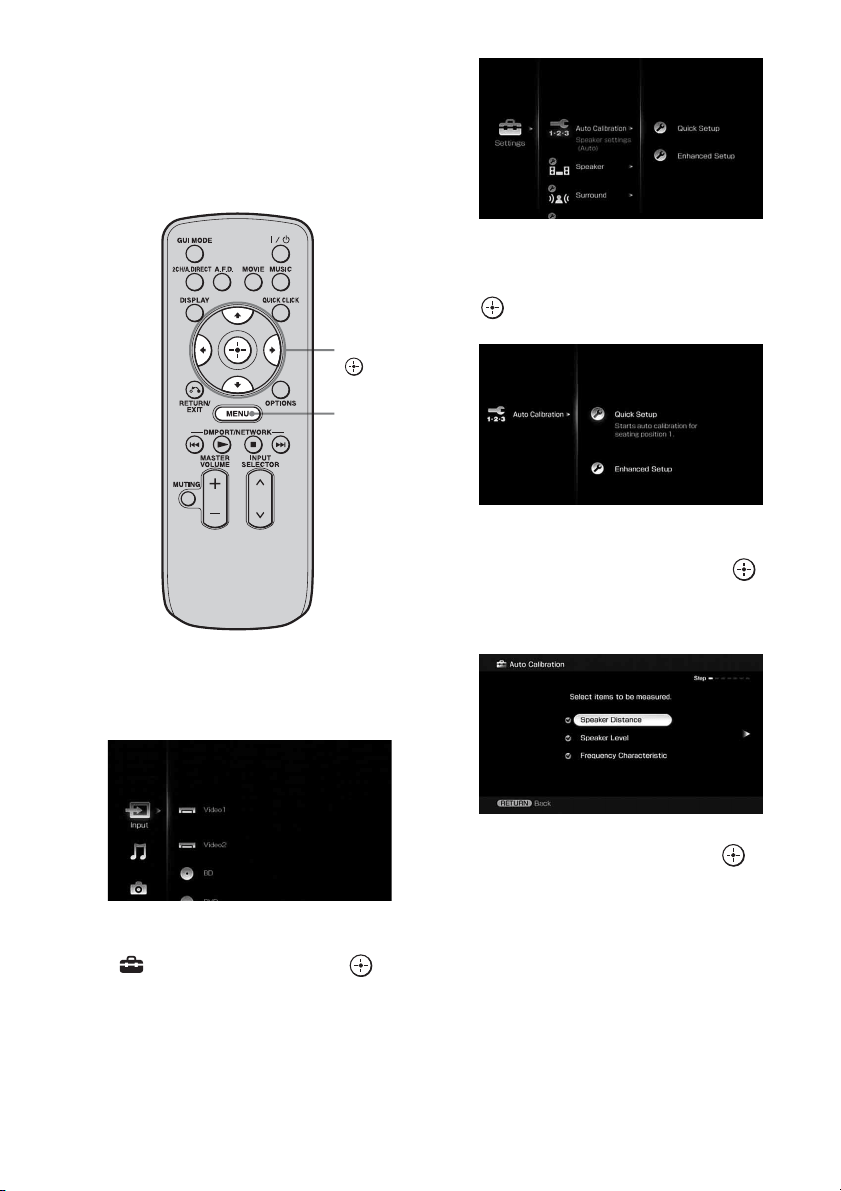
52
GB
c) • Signals with a sampling frequency of 88.2 kHz
and higher are always played back at either
44.1 kHz or 48 kHz.
• The measurement result is not utilized when
Dolby TrueHD signals with a sampling
frequency of 176.4 kHz and higher are being
received.
1 Press MENU.
The menu is displayed on the TV screen.
2 Press V/v repeatedly to select
“ Settings,” then press or
b.
The Settings menu list appears on the TV
screen.
3 Press V/v repeatedly to select
“Auto Calibration,” then press
or b.
4 Press V/v repeatedly to select
“Quick Setup,” then press .
The screen on which you can select the
item to be measured appears.
5 Press V/v repeatedly and to
un-check the items you do not
want to measure, then press b.
The confirmation screen, asking whether
you are ready to start measurement,
appears.
V/v/B/b,
MENU
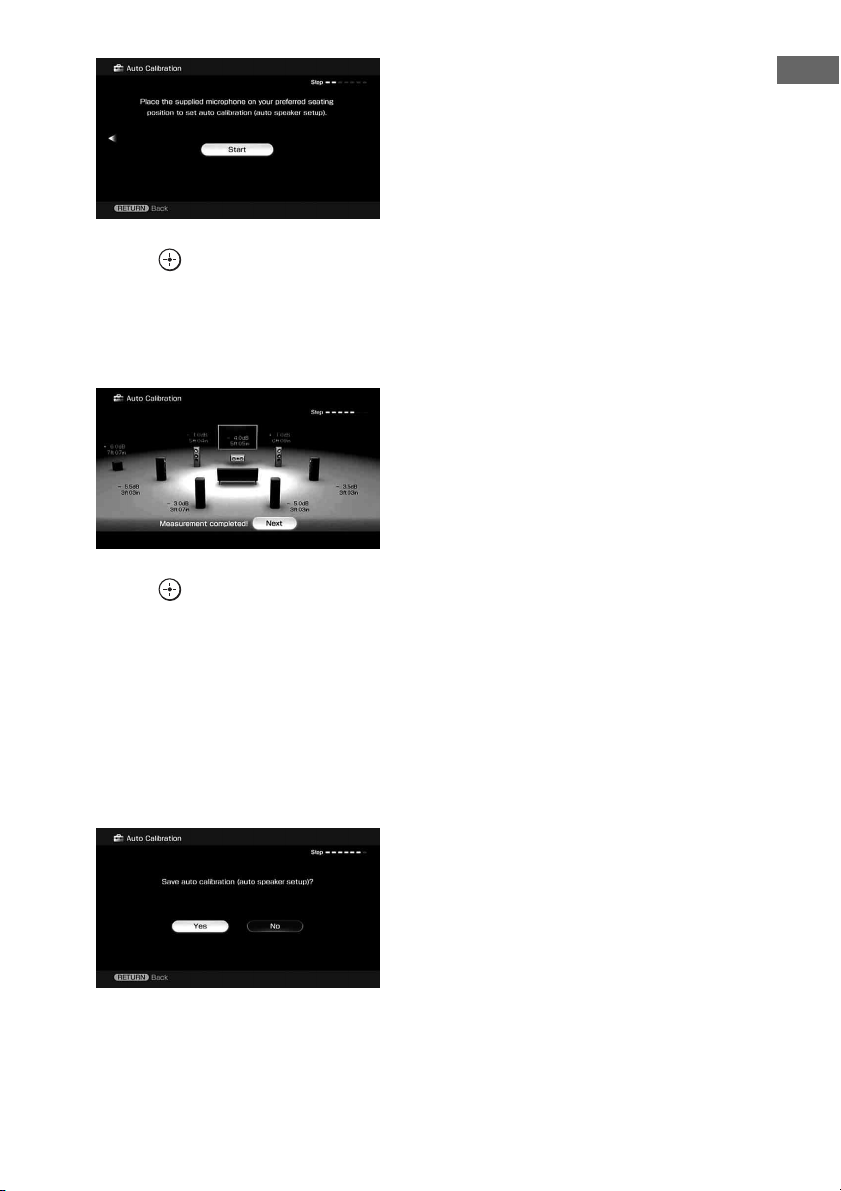
53
GB
Getting Started
6 Press to select “Start.”
The measurement starts in five seconds.
When the measurement ends, a beep
sounds and the measurement result
appears on the TV screen.
7 Press to select “Next.”
“Save auto calibration (auto speaker
setup)?” appears. To save the
measurement results, follow the steps in
“Saving the measurement results”
(page 54).
If a warning message or error code
appears on the screen, see “Message list
after auto calibration measurement”
(page 55).
Note
When the speaker(s) is (are) out of the phase, “Out
Phase” is displayed on the TV screen. The “+” and
“–” terminals of the speaker may be connected the
other way around. However, depending on the
speakers, “Out Phase” appears on the TV screen
even though the speakers are connected properly.
This is because of the speakers’ specifications. In
this case, you can continue to use the receiver.
Tips
• Operations other than turning the receiver on or off
are deactivated during the measurement.
• In the following situations, the measurements have
not been performed correctly or auto calibration
cannot be performed.
– when connecting special speakers, such as
dipole speakers.
– when using the zone 2/zone 3 function in zone 2/
zone 3.
• You can change the unit of distance use in
“Distance Unit” in the Speaker settings menu.
To cancel the measurement
The measurement is cancelled when you
change the volume, switch functions, change
the setting of the SPEAKERS switch, or
connect headphones.
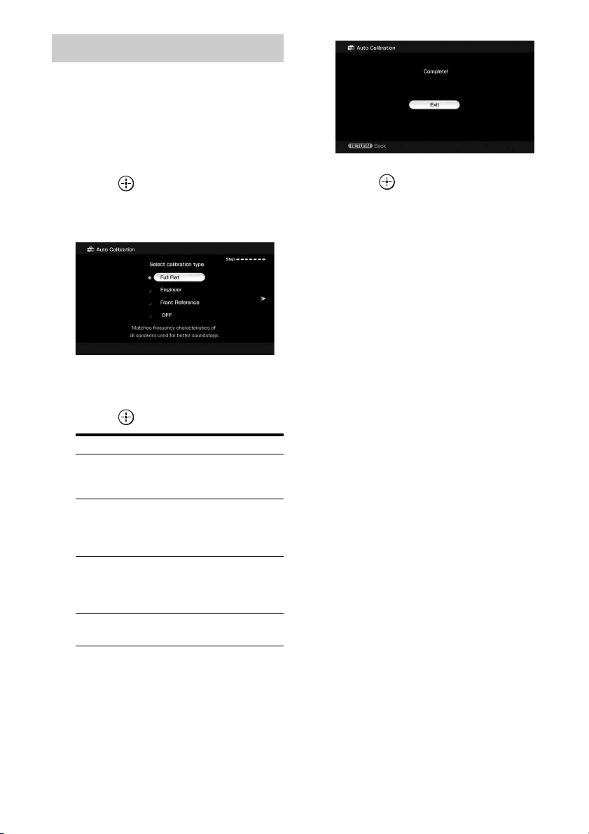
54
GB
To save the measurement results obtained in
“Performing auto calibration” (page 51),
proceed with the following steps.
1 Press B/b to select “Yes” in
step 7 in “Performing auto
calibration” (page 51), then
press .
The selecting screen of the calibration
type appears.
2 Press V/v repeatedly to select
the auto calibration type, then
press .
The measurement results are saved.
3 Press b.
The exit screen appears.
4 Press .
Notes
• After reflecting the results of a compensation for a
frequency characteristic, signals with a sampling
frequency of 88.2 kHz and higher are always
played back at either 44.1 kHz or 48 kHz.
• The frequency response measurement result is not
utilized in the following cases.
– The multi-channel input is selected.
– “2ch Analog Direct” is being used.
– Dolby TrueHD signals with a sampling
frequency of 176.4 kHz and higher are being
received.
Tip
The size of a speaker (LARGE/SMALL) is
determined by the low characteristics. The
measurement results may vary, depending on the
position of the optimizer microphone and speakers,
and the shape of the room. It is recommended that
you follow the measurement results. However, you
can change those settings in the Speaker settings
menu. Save the measurement results first, then try to
change the settings if you want.
Saving the measurement results
Parameter Explanation
Full Flat Makes the measurement of
frequency from each
speaker flat.
Engineer Sets the frequency to one
that matches that of the
Sony listening room
standard.
Front Reference Adjusts the characteristics
of all the speakers to match
the characteristics of the
front speaker.
OFF Sets the auto calibration EQ
to off.
55
GB
Getting Started
If a warning message or error code appears in
step 7 of “Performing auto calibration”
(page 51), check the problem of the error and
perform auto calibration again.
1 Press B/b to select “Yes,” then
press when “Error occurred
during calibration, press to
investigate.” appears on the
screen.
Confirm the details of the measurement
results, then proceed with the appropriate
remedy.
2 Press B/b to select “Retry,”
then press .
3 Repeat steps 5 to 7 in
“Performing auto calibration”
(page 51).
To save measurement results
that caused an error without
taking a remedy
1
Press B/b to select “No”, then press
when “Error occurred during
calibration, press to investigate.”
appears on the screen.
2 Follow the steps in “Saving the
measurement results” (page 54) to
save the measurement results.
Message list after auto calibration measurement
Checking the auto calibration
results
Display Explanation
Code 30 Headphones are connected. Remove the headphones and perform the auto calibration again.
Code 31 SPEAKERS (OFF/A/B/A+B) is set to OFF. Set it to others and re-perform the measurement.
Code 32 None of the speakers were detected. Make sure that the optimizer microphone is connected
properly and reperform the measurement.
If the optimizer microphone is connected properly but the error code appears, the optimizer
microphone cable may be damaged or improperly connected.
Code 33 • None of the front speakers are connected or only one front speaker is connected.
• The optimizer microphone is not connected.
• Either the left or right surround speaker is not connected.
• Surround back speakers are connected even though surround speakers are not connected.
Connect the surround speaker(s) to the SURROUND terminals.
• The surround back speaker is connected only to the SURROUND BACK SPEAKERS R
terminals. When you connect only one surround back speaker, connect it to the
SURROUND BACK SPEAKERS L terminals.
Code 34 Speakers are not placed in the proper position. Speakers or an optimizer microphone on the
right or left may be placed wrongly. See “1: Installing speakers” (page 21) and check the
speaker position.
Warning 40 The measurement has completed. However, the noise level is high. You may be able to
perform the measurement properly if you try it again, even though the measurement cannot
be performed in all environments. Try to perform the measurement in a quiet environment.
Warning 41
Warning 42
The input from the microphone is too big.
• It may be too close the distance between the speaker and the microphone.
Retry the measurement after setting apart from each other.
• It may be that the volume is too big when you use the receiver as a preamp.
Warning 43 The distance and position of a subwoofer cannot be detected. Or the angle of the speaker
position cannot be detected. This may be caused by noise. Try to perform the measurement
in a quiet environment.
continued

56
GB
Tip
Depending on the position of the subwoofer, the
measurement results for polarity may vary.
However, there will be no problems even if you
continue to use the receiver with that value.
Warning 44 Measurement has been completed. However the speakers are not placed in the proper position
with respect to each other. See “1: Installing speakers” (page 21) and check the relative
positions of the speakers.
NO WARNING There is no warning information.
---------- No speakers are connected.
Display Explanation
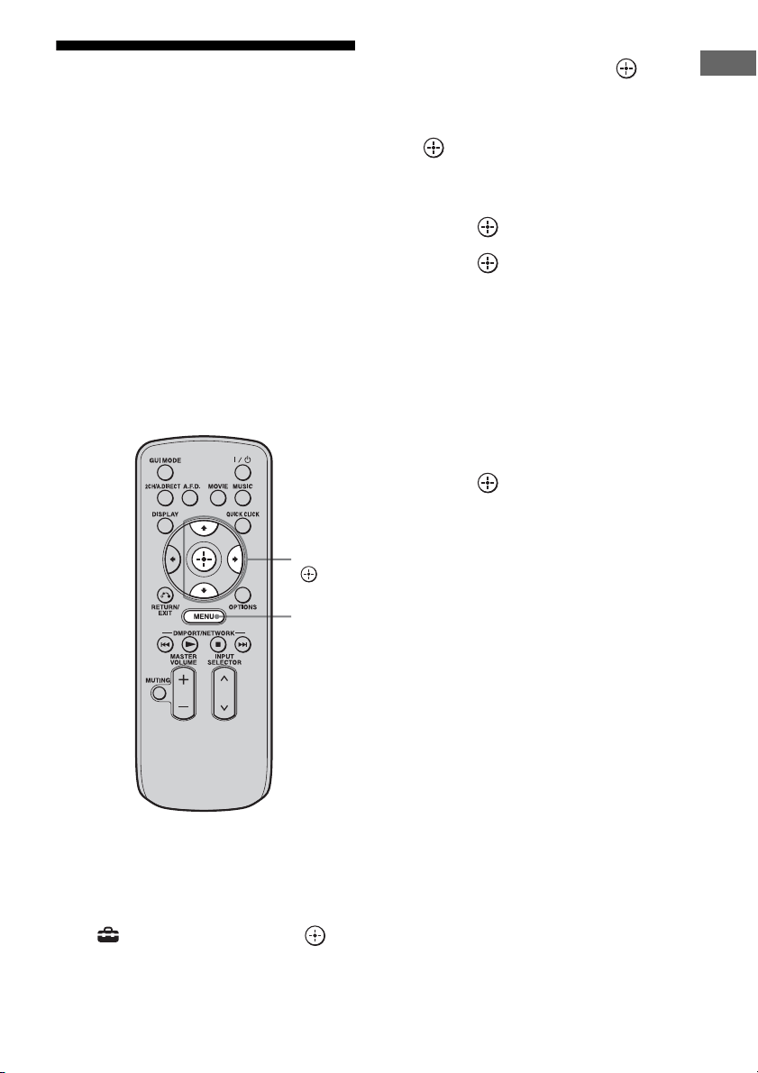
57
GB
Getting Started
9: Configuring the
network settings of the
receiver
The network settings for the receiver must be
set correctly to use the network functions of
the receiver.
You can make the required network settings
for the receiver by following the instructions
provided by an initial setup wizard.
The procedure used to set up the IP address
automatically (DHCP) is explained below.
In this case, the router that is connected to the
receiver or the Internet provider must support
DHCP.
1 Press MENU.
The menu is displayed on the TV screen.
2 Press V/v repeatedly to select
“ Settings,” then press or
b.
3 Press V/v repeatedly to select
“Network,” then press or b.
4 Press V/v repeatedly to select
“Network Setup,” then press
.
“Start Network function Setup Wizard”
appears on the TV screen.
5 Press to select “Next.”
6 Press to select “Connect
Automatically (DHCP).”
“Success! The receiver is now connected
to network.” appears on the TV screen
when you have succeeded in making a
connection.
If the failure screen is displayed, perform
the process referring to “Network Setup”
(page 144), after you have completed this
process.
7 Press to select “Finish.”
To set the network settings
manually
See “To set the IP address manually”
(page 144) or “To set the Proxy server
manually” (page 144).
Note
The wizard screen appears on the TV screen each
time you use the network function, until the network
function setup has been completed.
V/v/b,
MENU

58
GB
10: Preparing a computer
to use as a server
A server is a device which delivers content
(music, photos, and videos) to a DLNA device
on a home network.
You can play back content stored on a
computer on a home network with this receiver
via that network after you have installed
application software such as VAIO Media plus
which has a DLNA compliant sever function.
VAIO Media plus is an application software
that enables you to quickly find content on
your home network, such as music, photos,
and videos, and view the content on the
computer through the home network.
By connecting other devices to VAIO Media
plus, you can also find and view the content on
the connected devices through the home
network. For example, you can enjoy photos
and music, stored on your computer, on your
TV and audio device or play a TV program,
recorded with a hard disk recorder, on your
computer.
If you use a VAIO computer, you can deliver
content saved on an external hard disk drive or
in Network-Attached Storage (NAS).
Note
If you use a computer other than a VAIO, you can
only deliver content saved on the internal disk drive
of that computer.
Operating System
Windows XP Home Edition/Professional/
Media Center Edition 2004/Media Center
Edition 2005 (SP3, 32 bit)
Windows Vista Home Basic/Home Premium/
Business/Ultimate (SP1, 32 bit/64 bit)
Computer
Note
Sony does not guarantee trouble-free operation on
all computers that satisfy the system requirements.
Other software operating on background may affect
the operation of this software.
When you use VAIO Media plus as server
software, install on your computer the VAIO
Media plus application software provided on
the CD-ROM supplied with the receiver by
following steps below.
If an older version of VAIO Media plus has
already been installed on your computer,
uninstall the following three programs using
“Programs and Features” (for Windows Vista)
or “Add or Remove Programs” (for Windows
XP) in Control Panel beforehand.
• VAIO Media plus
• VAIO Content Folder Watcher
• VAIO Content Folder Setting
What you can do with VAIO
Media plus
System Requirements
Windows XP Windows Vista
Computer IBM PC/AT compatible
CPU Intel Celeron M
processor
1.40 GHz or higher
(Intel Core 2 Duo
1.80 GHz or higher
is recommended.)
Intel Core Duo
1.33 GHz or higher
(Intel Core 2 Duo
2.26 GHz or higher
is recommended.)
Memory 512 MB or more
(1 GB or more is
recommended.)
1 GB or more
(2 GB or more is
recommended.)
Graphic
chip
Equipped with graphic chip by Intel,
NVIDIA or ATI.
DirectX 9.0c compatible video card
(DirectX 9.0c/128 MB compatible
video card and the latest driver are
recommended.)
Display 800 × 600 or higher resolution
HDD 500 MB or more is recommended.
Network 100Base-TX or higher
Sound
card
Direct Sound compatible sound card
Installing the VAIO Media plus
application software on a
computer
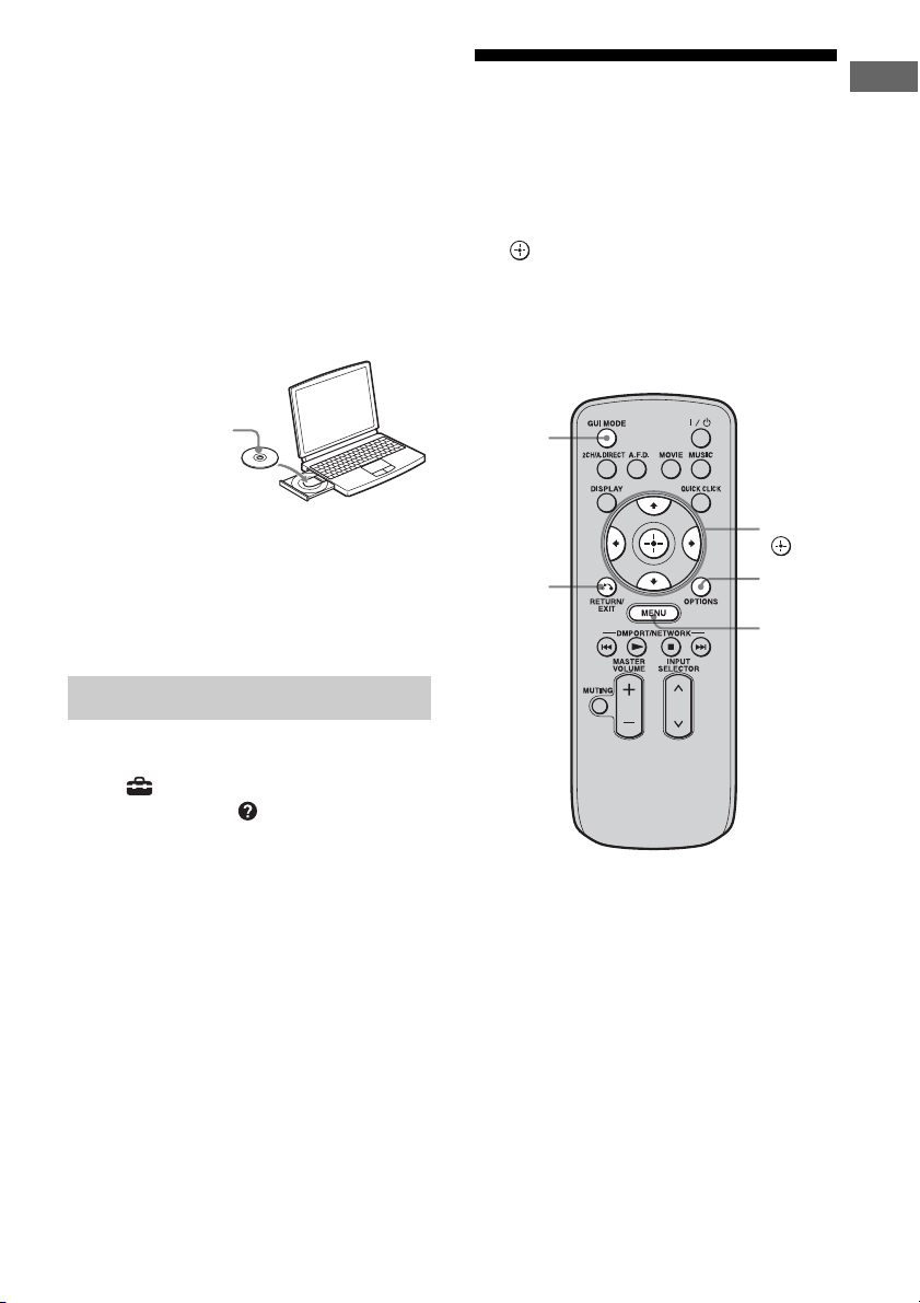
59
GB
Getting Started
1 Turn on your computer and
login as an administrator.
2 Insert the supplied CD-ROM
into the CD-ROM drive of your
computer.
The installation launcher starts
automatically, then a Software Setup
window appears on the screen.
If installation launcher does not start
automatically, double-click
“SetupLauncher.exe” on the disc.
3 Install the VAIO Media plus
application software following
the instructions given in the
message on the screen.
For VAIO Media plus operations, refer to the
help files.
Click “ Settings” in the Home Menu
window, then select “ Help” to display help
files.
Guide to on-screen
display operation
You can display the menu of the receiver on
the TV screen and select the function you want
to use on the TV screen by pressing V/v/B/b
and on the remote.
To display the menu of the receiver on the TV
screen, make sure that the receiver is in “GUI
MODE” following the step in “To turn “GUI
MODE” on and off” (page 60).
Referring to help files
CD-ROM (VAIO Media
plus application
software) (supplied)
V/v/B/b,
MENU
RETURN/
EXIT O
OPTIONS
GUI
MODE
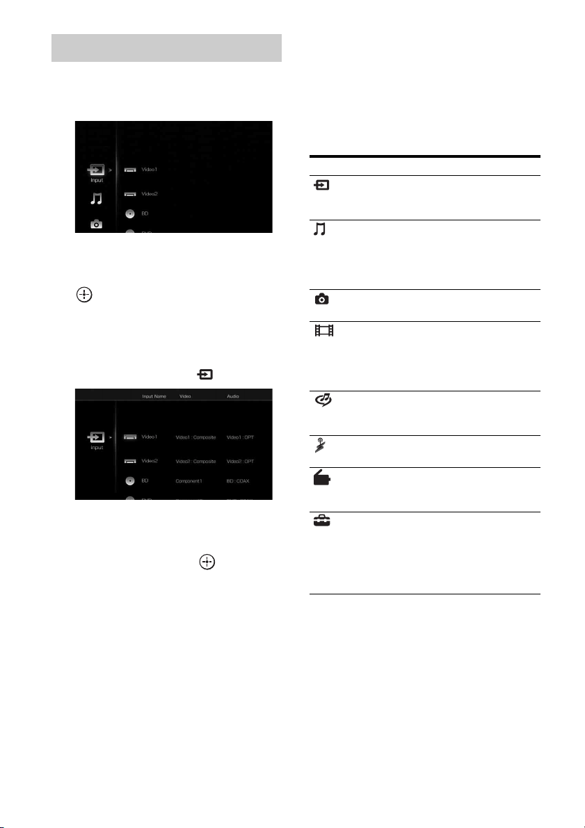
60
GB
1 Press MENU.
The menu is displayed on the TV screen.
2 Press V/v repeatedly to select
the menu you want, then press
or b to enter the menu
mode.
The menu item list appears on the TV
screen.
Example: When you select “ Input”
3 Press V/v repeatedly to select
the menu item you want to
adjust, then press to enter
the menu item.
4 Repeat steps 2 and 3 to select
the parameter you want.
To return to the previous screen
Press RETURN/EXIT O.
To exit the menu
Press MENU.
To turn “GUI MODE” on and off
Press GUI MODE. “GUI MODE ON” or
“GUI MODE OFF” is displayed in the
display window of the receiver, depending
on the mode selected.
Overview of the main menus
Using the menu
Menu icon Description
Input Selects the input source
component connected to the
receiver (page 62).
Music Selects the music from the
audio component connected
to the DIGITAL MEDIA
PORT adapter (page 64) or
server on the home network.
Photo Select the photos from the
server on the home network.
Video Select the images from the
video component connected
to the DIGITAL MEDIA
PORT adapter (page 64) or
server on the home network.
Rhapsody Selects the Rhapsody radio
service (page 98). Rhapsody
is only available in the US.
SHOUTcast Selects the SHOUTcast radio
service (page 101).
FM/AM/XM/
SIRIUS
Selects the built-in FM/AM
radio or satellite tuner
connected (page 68, 73).
Settings You can adjust the settings of
the speakers, the surround
effect, equalizer, audio,
video and other inputs
connected to the HDMI jacks
(page 127).

61
GB
Getting Started
When you press OPTIONS, the option menus
for the selected main menu are displayed. You
can select a related function without
reselecting the menu.
1 Press MENU.
The menu is displayed on the TV screen.
2 Press V/v repeatedly to select a
menu you want, then press
or b to enter the menu mode.
The menu item list appears on the TV
screen.
Example: When you select “ Input”
3 Press OPTIONS while the menu
item list is displayed.
The option menu appears.
4 Press V/v repeatedly to select
the option menu item you want,
then press .
5 Press V/v repeatedly to select
the parameter you want, then
press .
To exit the menu
Press MENU.
Using the option menus
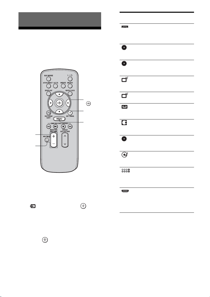
62
GB
Enjoying sound/images
from the component
connected to the receiver
1
Press MENU.
The menu is displayed on the TV screen.
2 Press V/v repeatedly to select
“ Input,” then press or b.
The menu item list appears on the TV
screen.
3 Press V/v repeatedly to select
the component you want, then
press .
The menu screen disappears and the
playback screen of the external input
appears.
4 Turn on the component and
start playback.
5 Press MASTER VOLUME +/– to
adjust the volume.
Tips
• You can adjust the volume differently depending
on the speed with which you turn the MASTER
VOLUME knob.
Playback
MASTER
VOLUME
MUTING
OPTIONS
MENU
V/v/B/b,
Selected input Components that
can be used
Video1,
Video2
VIDEO 1, 2 VCR, etc.,
connected to the
VIDEO 1 or VIDEO 2
jack.
BD Blu-ray Disc Player,
etc., connected to the
BD jack.
DVD DVD player, etc.,
connected to the DVD
jack.
SAT Satellite tuner, etc.,
connected to the SAT
jack.
TV TV connected to the TV
jack.
Tape Tape deck, etc.,
connected to the TAPE
jack.
MD MD deck, etc.,
connected to the MD
jack.
SA-CD/CD Super Audio CD or CD
player, etc., connected
to the SA-CD/CD jack.
Phono Turntable, etc.,
connected to the
PHONO jack.
Multi in Component connected
to the MULTI
CHANNEL INPUT
jack.
HDMI1, 2, 3,
4, 5, 6
HDMI components
connected to the
HDMI1, HDMI2,
HDMI3, HDMI4,
HDMI5, or HDMI6 jack.
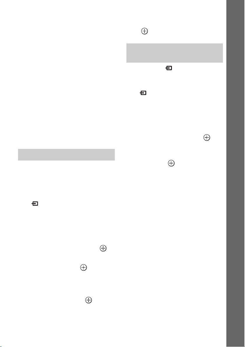
63
GB
Playback
To turn the volume up or down quickly: turn the
knob quickly.
To make fine adjustment: turn the knob slowly.
• You can adjust the volume differently depending
on the length of time you press and hold the
MASTER VOLUME +/– button on the remote.
To turn the volume up or down quickly: press and
hold the button.
To make a fine adjustment: press the button and
release it immediately.
To activate the muting function
Press MUTING on the remote. To cancel,
press MUTING on the remote again or press
MASTER VOLUME + to raise the volume.
To avoid damaging your
speakers
Before you turn off the receiver, be sure to turn
down the volume level.
You can enter a name of up to 8 characters for
inputs and display it.
This is convenient for labeling the jacks with
the names of the connected components.
1 Press V/v repeatedly on the
“ Input” screen to select the
input you want to name.
2 Press OPTIONS.
The option menu appears.
3 Press V/v repeatedly to select
“Name Input,” then press .
The soft keyboard appears on the screen.
4 Press V/v/B/b and to select
a character one by one to enter
the name.
5 Press V/v/B/b to select
“Finish,” then press .
The name you entered is registered.
To cancel naming input
Press V/v/B/b to select “Cancel,” then
press .
When you select “ Input,” you can change
the items to be displayed.
1 Press V/v repeatedly on the
“ Input” screen to select the
input you want.
2 Press OPTIONS.
The option menu appears.
3 Press V/v repeatedly to select
“List Mode,” then press .
4 Press V/v repeatedly to select
the item you want to display,
then press .
• Input Assign
Input name and audio/video input jack
assigned to the input are displayed in a
list.
• Sound Field
Input name and the sound field selected
for the input are displayed in a list.
•A/V Sync
Input name and the delay set on the “A/
V Sync” menu for the input are
displayed in a list.
Naming the input (Name Input)
Changing the display items (List
Mode)
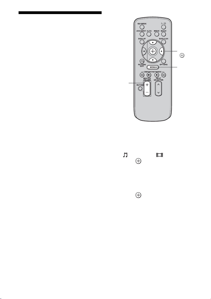
64
GB
Enjoying sound/images
from the components
connected to the DIGITAL
MEDIA PORT
The DIGITAL MEDIA PORT is for enjoying
sound/images from a portable audio source or
computer by connecting a DIGITAL MEDIA
PORT adapter.
Available DIGITAL MEDIA PORT adapters
vary in each area.
For details on connecting the DIGITAL
MEDIA PORT adapter, see “Connecting
components with digital audio input/output
jacks” (page 28).
You can use the following Sony DIGITAL
MEDIA PORT adapters:
• TDM-BT1/BT10 Bluetooth™ Wireless
Audio Adapter
• TDM-NW10 DIGITAL MEDIA PORT
Adapter
• TDM-iP10/iP50 DIGITAL MEDIA PORT
Adapter
• TDM-MP10 DIGITAL MEDIA PORT
Adapter
The DIGITAL MEDIA PORT adapter is an
optional product.
Notes
• Do not connect an adapter other than the DIGITAL
MEDIA PORT adapter.
• Before disconnecting the DIGITAL MEDIA PORT
adapter, make sure to turn the receiver off using the
remote.
• Do not connect or disconnect the DIGITAL
MEDIA PORT adapter to/from the receiver while
the system is turned on.
• Depending on the type of DIGITAL MEDIA
PORT adapter, the images are also output.
• Do not connect to the receiver a DIGITAL MEDIA
PORT adapter that uses a network function such as
TDM-NC1 Wireless Network Audio Client.
You can use the network function of the receiver
without using a DIGITAL MEDIA PORT adapter.
1 Press MENU.
The menu is displayed on the TV screen.
2 Press V/v repeatedly to select
“ Music” or “ Video,” then
press or b.
3 Press V/v repeatedly to select
“DMPORT” or a component
connected to the DIGITAL
MEDIA PORT adapter, then
press .
The component connected to the
DIGITAL MEDIA PORT adapter is
recognized and “DMPORT” on the screen
will change to the respective component’s
name with an icon. If the adapter
connected cannot be recognized,
“DMPORT” is displayed on the TV
screen.
MASTER
VOLUME
V/v/b,
MENU
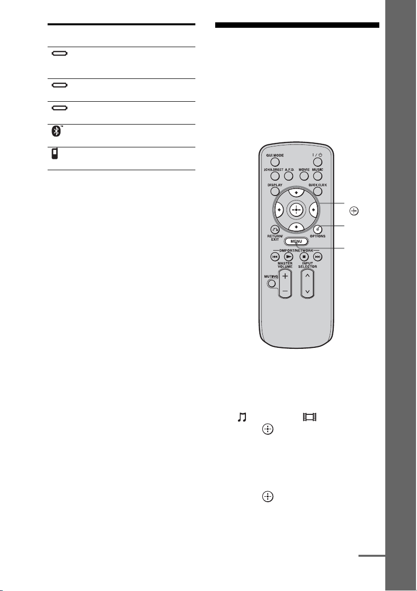
65
GB
Playback
4 Select a track you want to play
using the component
connected to the DIGITAL
MEDIA PORT adapter.
5 Press MASTER VOLUME +/– to
adjust the volume.
Operating the TDM-iP50
using the GUI menu of the
receiver
Make sure that “System GUI” is selected in
step 4 in “Changing the operation screen using
the DIGITAL MEDIA PORT” (page 67).
1 Press MENU.
The menu is displayed on the TV screen.
2 Press V/v repeatedly to select
“ Music” or “ Video,” then
press or b.
3 Press V/v repeatedly to select
the component connected to
the DIGITAL MEDIA PORT
adapter you want to play, then
press .
The contents list appears.
Icon Component that is
connected
DMPORT
A component other than one
of the following is
connected.
iPod The iPod model recognized
is connected.
Walkman The Network Walkman
recognized is connected.
Bluetooth The Bluetooth drive
recognized is connected.
Mobile
Phone
The Mobile Phone
recognized is connected.
OPTIONS
MENU
V/v/B/b,
continued

66
GB
4 Press V/v/B/b and to select
track or content from the
contents list.
The following content lists are just
examples. They may vary depending on
the components connected to the receiver.
In case of iPod
5 Press MASTER VOLUME +/– to
adjust the volume.
1 Play back the track you want to
listen to following the steps
outlined in “Operating the TDM-
iP50 using the GUI menu of the
receiver” (page 65).
2 Press OPTIONS.
The option menu appears.
3 Press V/v repeatedly to select
“Shuffle,” “Repeat,” or
“Audiobook Speed,” then press
.
4 Press V/v repeatedly to select
the mode you want to select
from the following, then press
.
x Shuffle
Plays all the tracks in random order.
•Off
Deactivates the shuffle play mode.
•Albums
Plays all the tracks on an album in random
order.
• Songs
Plays all the tracks in “Songs” in random
order.
x Repeat
Plays one or all the tracks repeatedly.
•Off
Deactivates the repeat play mode.
•One
Plays one track repeatedly.
•All
Plays all the tracks repeatedly.
x Audiobook Speed
Selects the display speed of the Audiobook.
•Low
Slows the display speed.
•Normal
Sets the display speed to standard.
•High
Increases the display speed.
DIGITAL MEDIA PORT message
list
Music Playlists > Playlist > Track
Artists > Artist > Album > Track
Albums > Album > Track
Songs > Track
Genres > Genre > Artist > Album > Track
Composers > Composer > Album > Track
Audiobooks > Track
Video Movies > Content
TV Shows > Episode > Content
Music Videos > Artist > Content
Video Podcast > Episode > Content
Selecting the playback mode
Message appears Explanation
No Adapter The adapter is not connected.
No Device There is no device connected
to the adapter.
No Audio No audio file was found.
Loading The data is being read.
No Item No item was found.
67
GB
Playback
You can change the operation screen using the
GUI menu. The DMPORT Control mode is
supported by the DIGITAL MEDIA PORT
adapters like TDM-iP50. This mode is not
supported by other adapters.
1 Press V/v repeatedly on the
“ Music” or “ Video”
screen to select the DIGITAL
MEDIA PORT adapter you want,
then press or b.
2 Press OPTIONS.
The option menu appears.
3 Press V/v to select “DMPORT
Control,” then press .
If “DMPORT Control” is not displayed,
refer to the operating instructions
supplied with component for details on
operating that component.
4 Press V/v repeatedly to select
the mode you want, then press
.
You can select the following modes in this
menu;
• System GUI
This mode is for the TDM-iP50. The list
of tracks will be displayed on the GUI
screen of the receiver. You can select a
track you want and play back it on each
GUI screen.
• Adapter GUI
This mode is for the TDM-iP50. The
menu of the adapter will be displayed on
the TV screen.
•iPod
This mode can be selected only when
the TDM-iP50 is connected.
To operate the TDM-iP50 using
the adapter menu
Make sure that “Adapter GUI” is selected in
step 4 in “Changing the operation screen using
the DIGITAL MEDIA PORT” (page 67).
For details on operating the adapter using the
adapter GUI menu, refer to the operating
instructions supplied with the adapter you are
using.
To operate the TDM-iP50 using
the iPod menu
Make sure that “iPod” is selected in step 4 in
“Changing the operation screen using the
DIGITAL MEDIA PORT” (page 67).
For details on operating the iPod, refer to the
operating instruction supplied with the iPod.
Changing the operation screen
using the DIGITAL MEDIA PORT
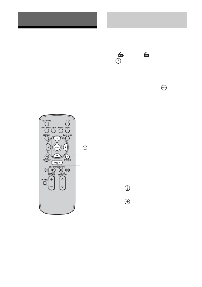
68
GB
Listening to FM/AM radio
You can listen to FM and AM broadcasts
through the built-in tuner. Before operation,
make sure you have connected the FM and
AM antennas (aerials) to the receiver
(page 44).
Tip
The tuning scale for direct tuning is shown below.
• FM band 100 kHz (USA/Canadian model)
50 kHz (European model)
• AM band 10 kHz* (USA/Canadian model)
9 kHz (European model)
* The AM tuning scale can be changed (page 71).
1 Press MENU.
The menu is displayed on the TV screen.
2 Press V/v repeatedly to select
“ FM” or “ AM,” then press
or b.
The FM or AM menu list appears on the
TV screen.
3 Press V/v to select “Auto
Tuning,” then press .
4 Press V/v.
Press V to scan from low to high, press v
to scan from high to low.
The receiver stops scanning whenever a
station is received.
In case of poor FM stereo
reception
1
Tune in the station you want to listen to
using Auto Tuning, Direct Tuning
(page 69), or select the preset station
you want (page 72).
2 Press OPTIONS.
The option menu appears.
3 Press V/v to select “FM Mode,” then
press .
4 Press V/v to select “MONO,” then
press .
Tuning
OPTIONS
MENU
V/v/b,
Tuning into a station
automatically (Auto Tuning)
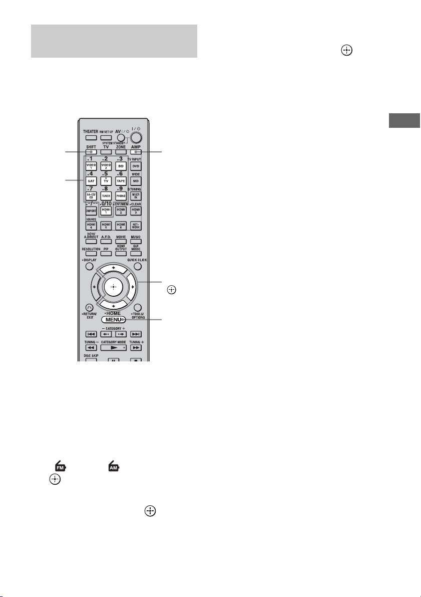
69
GB
Tuning
Enter the frequency of a station directly by
using the numeric buttons on the multifunction
remote. This operation cannot be performed
using the simple remote.
1 Press AMP.
The receiver can be operated using the
remote.
2 Press MENU.
The menu is displayed on the TV screen.
3 Press V/v repeatedly to select
“FM” or “AM,” then press
or b.
4 Press V/v to select “Direct
Tuning,” then press .
5 Press SHIFT, then press the
numeric buttons to enter the
frequency, then press .
Example 1: FM 102.50 MHz
Select 1 b 0 b 2 b 5 (b 0*)
Example 2: AM 1,350 kHz
Select 1 b 3 b 5 b 0
*Press the numeric button 0 when you are
using the European model.
Tip
If you have tuned in an AM station, adjust the
direction of the AM loop antenna (aerial) for
optimum reception.
If you cannot tune in a station
“– – – .– – MHz” appears and then the display
returns to the current frequency.
Make sure you have entered the right
frequency. If not, repeat step 5. If you still
cannot tune in a station, the frequency is not
used in your area.
Tuning into a station directly
(Direct Tuning)
AMP
V/v/b,
MENU
Numeric
buttons
SHIFT

70
GB
This receiver also allows you to use RDS
(Radio Data System), which enables radio
stations to send additional information along
with the regular program signal. You can
display RDS information.
Select a station on the FM band you
want to listen to using Auto Tuning
(page 68) or Direct Tuning.
When you tune in a station that provides RDS
services, the Program Service Name and
Program Type are displayed on the TV screen.
Notes
• RDS is operable only for FM stations.
• Not all FM stations provide RDS service, nor do
they provide the same type of services. If you are
not familiar with the RDS services in your area,
check with your local radio stations for details.
• RDS may not work properly if the station you
tuned to is not transmitting the RDS signal
properly or if the signal strength is weak.
• If there is an emergency announcement by
government authorities, “Alarm-Alarm!” flashes in
the display.
• If a station does not provide a particular RDS
service, “No XX” (such as “No Clock Time”)
appears on the display.
Receiving RDS broadcasts
(European model only)
Program type
indication
Description
News News programs
Current Affairs Topical programs that expand on
current news
Information Programs offering information on
a wide spectrum of subjects,
including consumer affairs and
medical advice
Sport Sports programs
Education Educational programs, such as
“how-to” and advice programs
Drama Radio plays and serials
Cultures Programs about national or
regional culture, such as language
and social concerns
Science Programs about the natural
sciences and technology
Varied Speech Other types of programs such as
celebrity interviews, panel
games, and comedy
Pop Music Popular music programs
Rock Music Rock music programs
Easy Listening Easy Listening
Light Classics M Instrumental, vocal, and choral
music
Serious Classics Performances of major
orchestras, chamber music,
opera, etc.
Other Music Music that does not fit into any
categories above, such as Rhythm
& Blues and Reggae
Weather & Metr Weather information
Finance Stock market reports and trading,
etc.
Children’s Progs Programs for children
Social Affairs Programs about people and the
things that affect them
Religion Programs of religious content
Phone In Programs where members of the
public express their views by
phone or in a public forum
Travel & Touring Programs about travel. Not for
announcements that are located
by TP/TA.
Leisure &
Hobby
Programs on recreational
activities such as gardening,
fishing, cooking, etc.
Jazz Music Jazz programs
Country Music Country music programs
National Music Programs featuring the popular
music of the country or region
Oldies Music Programs featuring oldies music
Folk Music Folk music programs
Documentary Investigative features
None Any programs not defined above
Program type
indication
Description
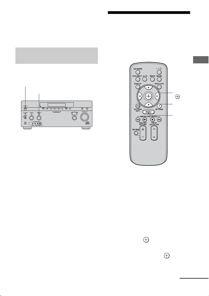
71
GB
Tuning
• When a station broadcasts radio text data, it is
displayed at the same rate at which it is sent from
the station. Any change in this rate is reflected in
the display rate of the data.
• The RDS information is shown on the display of
this receiver.
You can change the AM tuning scale to either
9 kHz or 10 kHz on the receiver.
1 Press POWER to turn off the
receiver.
2 While holding down TUNING
MODE, press POWER on the
receiver.
3 Change the current AM tuning
scale to 9 kHz (or 10 kHz).
To reset the scale to 10 kHz (or 9 kHz),
repeat the procedure above.
Note
All preset stations will be erased when you change
the tuning scale.
Presetting FM/AM radio
stations
You can preset up to 30 FM and 30 AM
stations. Then you can easily tune in the
stations you often listen to.
1 Tune in the station that you
want to preset using Auto
Tuning (page 68) or Direct
Tuning (page 69).
In case of poor FM stereo reception,
switch the FM reception mode (page 68).
2 Press OPTIONS.
The option menu appears.
3 Press V/v to select “Memory,”
then press .
4 Press V/v to select a preset
number, then press .
The station is stored as the selected preset
number.
Changing the AM tuning scale
(USA/Canadian model only)
POWER
TUNING MODE
V/v/B/b,
MENU
OPTIONS
continued
72
GB
5 Repeat steps 1 to 4 to preset
another station.
You can store stations as follows:
• AM band: AM1 to AM30
• FM band: FM1 to FM30
1 Press MENU.
The menu is displayed on the TV screen.
2 Press V/v repeatedly to select
“ FM” or “ AM,” then press
or b.
3 Press V/v to select the preset
number station you want.
Preset numbers from 1 to 30 are available.
1 On “FM” or “AM” screen,
press V/v to select the preset
number on which you want to
name.
2 Press OPTIONS.
The option menu appears.
3 Press V/v repeatedly to select
“Name Input,” then press .
The soft keyboard appears on the screen.
4 Press V/v/B/b and to select
a character one by one to enter
the name.
5 Press V/v/B/b to select
“Finish,” then press .
The name you entered is registered.
To cancel naming input
Press V/v/B/b to select “Cancel,” then
press .
Tuning to preset stations
Naming preset stations (Name
Input)

73
GB
Tuning
Listening to satellite
radio
(USA/Canadian model only)
To listen to Satellite Radio, you’ll need to
connect either a SIRIUS or XM Satellite Radio
tuner (sold separately) to your satellite-ready
receiver. Satellite Radio is available to
residents of the US (except Alaska and
Hawaii) and Canada.
Satellite Radio delivers a variety of
commercial-free music from categories
ranging from Pop, Rock, Country, R&B,
Dance, Jazz, Classical and many more plus
coverage of all the top professional and college
sports including play by play games from
select leagues and teams. Additional
programming includes expert sports talk,
uncensored entertainment, comedy, family
programming, local traffic and weather and
news from your most trusted sources.
Whether you purchase a SIRIUS or XM tuner,
you’ll need to activate and subscribe to begin
enjoying the service. Easy to follow
installation and setup instructions are provided
with the satellite tuners. Whichever service
you choose, there are a variety of
programming packages available, including
the option of adding “The Best of SIRIUS”
programming to your XM tuner or “The Best
of XM” programming to your SIRIUS tuner,
enabling you to enjoy the most popular
programming among both services. The “Best
of” packages are not available to SIRIUS or
XM Canada subscribers at this time.
Family friendly packages are also available to
restrict channels featuring content that may be
inappropriate for children.
To subscribe to XM, U.S. customers should
visit xmradio.com or call 1-800-XMRADIO
(1-800-967-2346); Canadian customers
should visit xmradio.ca or call XM Listener
Care at 1-877-GETXMSR (1-877-438-9677).
To subscribe to SIRIUS, U.S. and Canadian
customers can call 1-888-539-SIRI (1-888-
539-7474) or visit sirius.com (US) or
siriuscanada.ca (Canada).
SIRIUS, XM and all related marks and logos are
trademarks of Sirius XM Radio Inc. and its
subsidiaries. All other marks and logos are the
property of their respective owners. All rights
reserved. SIRIUS and XM subscriptions sold
separately. Taxes and a one-time activation fee may
apply. XM tuners and home docks or SIRIUS tuners
(each sold separately) are required to receive the
SIRIUS or XM satellite radio service. All
programming and fees subject to change. It is
prohibited to copy, decompile, disassemble, reverse
engineer, hack, manipulate or otherwise make
available any technology or software incorporated in
receivers compatible with the SIRIUS or XM
Satellite Radio Systems. Service not available in
Alaska and Hawaii.
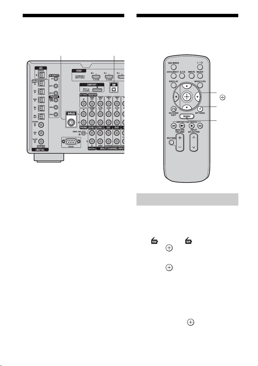
74
GB
Connecting a satellite
radio tuner
To connect to the XM jack
Before operating the system, connect the XM
Mini-Tuner and Home Dock to the XM jack.
Note
To ensure optimal reception of XM’s satellite signal,
move your antenna to various window locations
around your home to see where the best reception
will be received. Most XM customers place the
antenna in a south-facing window with a clear view
to the sky.
To connect to the SIRIUS jack
Connect the SiriusConnect Home tuner. When
you use the SiriusConnect Home tuner with
this receiver, be sure to connect the AC power
adaptor supplied with the tuner to a wall outlet.
Keep the SiriusConnect Home tuner, antenna,
and AC power adaptor away from the speaker
cords and the power cord to avoid picking up
noise.
Preparing to listen to a
satellite radio
1
Press MENU.
The menu is displayed on the TV screen.
2 Press V/v repeatedly to select
“ XM” or “ SIRIUS,” then
press or b.
3 Press V/v to select “ALL,” then
press or b.
When the “Preset Mode” screen is
displayed, change the tuning mode to
“Category Mode,” then select “ALL.”
Press OPTIONS, then press V/v
repeatedly to select “Category Mode.”
4 Press V/v to select the channel
0, then press .
XM jackSIRIUS jack
Checking the ID number
V/v/b,
MENU
OPTIONS
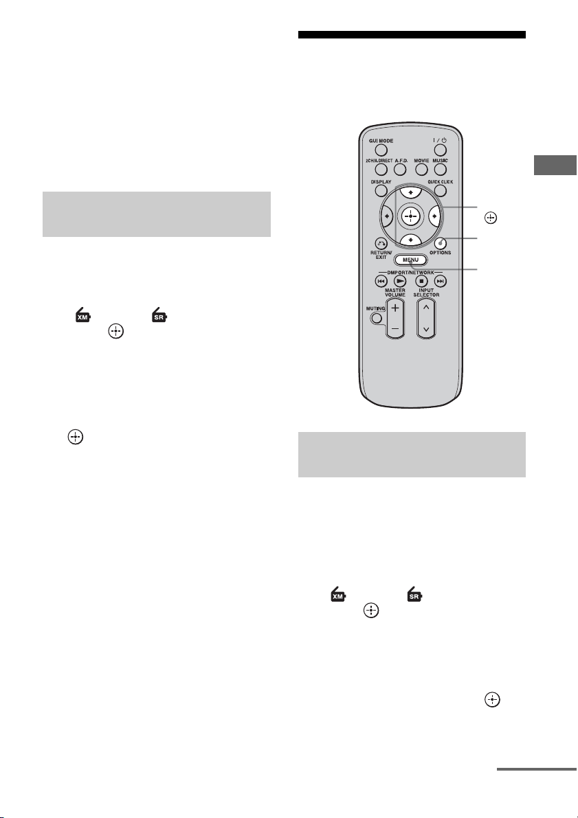
75
GB
Tuning
5 Check the XM Radio ID or Sirius
ID on the TV screen and write it
in the space provided here.
XM Radio ID:_____________________
Sirius ID:_________________________
You can also check the XM Radio ID and
Sirius ID using the display on the
receiver.
1 Press MENU.
The menu is displayed on the TV screen.
2 Press V/v repeatedly to select
“XM” or “SIRIUS,” then
press or b.
3 Press OPTIONS.
The option menu appears.
4 Press V/v repeatedly to select
“Antenna Aiming,” then press
.
The Antenna Aiming screen appears.
5 While checking the quality of
the reception, adjust the
direction of the antenna to
obtain the best reception.
To exit the menu
Press MENU.
Selecting a channel of the
satellite radio
You can select a channel from one category or
all the categories.
1 Press MENU.
The menu is displayed on the TV screen.
2 Press V/v repeatedly to select
“ XM” or “ SIRIUS,” then
press or b.
3 Press OPTIONS.
The option menu appears.
4 Press V/v repeatedly to select
the category, then press .
• ALL: You can select a channel from all
the categories.
Checking receiving conditions
(Antenna Aiming)
Selecting a channel by category
(Category Mode)
V/v/b,
MENU
OPTIONS
continued
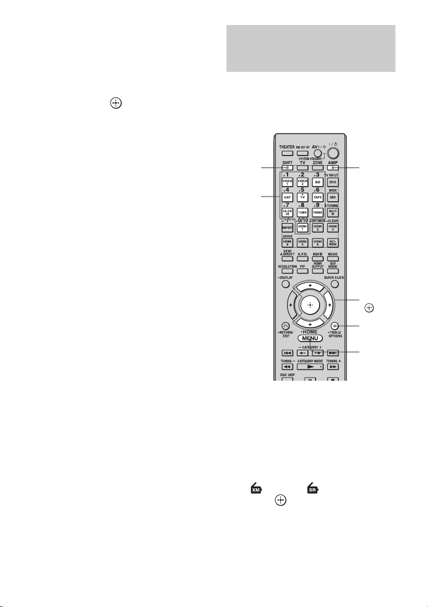
76
GB
• (category name): You can select a
channel from one category.
When the “Preset Mode” screen is
displayed, press OPTIONS, then press V/
v repeatedly to select “Category Mode.”
5 Press V/v to select the channel,
then press .
The selected channel is being received.
The channel information is displayed on
the TV screen.
Note
When you select a channel in the “Category Mode,”
the channel you selected may not be the one in the
category you want. This is because one channel may
belong to more than one category.
Enter the channel number directly by using the
numeric buttons on the multifunction remote.
This operation cannot be performed using the
simple remote.
1 Press AMP.
The receiver can be operated using the
remote.
2 Press MENU.
The menu is displayed on the TV screen.
3 Press V/v repeatedly to select
“ XM” or “ SIRIUS,” then
press or b.
4 Press OPTIONS.
The option menu appears.
Selecting a channel by inputting
the channel number directly
(Direct Tuning)
AMP
V/v/b,
MENU
Numeric
buttons
SHIFT
OPTIONS
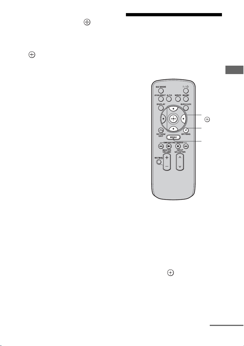
77
GB
Tuning
5 Press V/v to select “Direct
Tuning,” then press .
6 Press SHIFT, then press the
numeric buttons to enter the
channel number, then press
.
The selected channel is tune in.
Presetting satellite radio
channels
You can select the channels you want directly
by presetting them using the preset numbers.
You can preset up to 30 XM Radio channels
and 30 SIRIUS Satellite Radio channels.
1 Select a channel you want to
preset using Category Mode
(page 75) or Direct Tuning
(page 76).
2 Press OPTIONS.
The option menu appears.
3 Press V/v to select “Memory,”
then press .
The preset number selection screen
appears.
V/v/b,
MENU
OPTIONS
continued
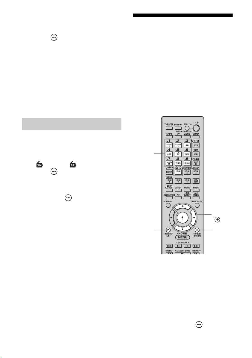
78
GB
4 Press V/v repeatedly to select
the preset number you want to
use as the preset channel, then
press .
Preset channels from 1 to 30 are available,
and a default channel is preset for all the
preset channels when you purchase the
receiver.
The selected channel is registered as the
preset channel you selected in step 1.
5 Repeat steps 1 to 4 to preset
another channel.
You can store channels from 1 to 30.
1 Press MENU.
The menu is displayed on the TV screen.
2 Press V/v repeatedly to select
“ XM” or “ SIRIUS,” then
press or b.
3 Press V/v to select the preset
number from the preset list,
then press .
You can select stored preset channels
from 1 to 30.
Notes
• The channel information you have preset may be
changed if XM Satellite Radio Inc. or SIRIUS
Satellite Radio Inc. change their channel
programming.
• When the “Category Mode” screen is displayed,
press OPTIONS, then press V/v to select “Preset
Mode.”
Restricting access to
specific channels
(Parental Lock) (SIRIUS only)
You can restrict access to certain channels
using your own lock code. The lock code is set
to “0000” as the default. Use the multifunction
remote for this operation. This operation
cannot be performed using the simple remote.
Change the lock code before you use this
function for the first time. See “To change the
lock code (Lock Code)” (page 79).
1 Select a channel you want to
lock using Category Mode
(page 75) or Direct Tuning
(page 76).
2 Press OPTIONS.
The option menu appears.
3 Press V/v to select “Parental
Lock,” then press or b.
Selecting preset channels
V/v/b,
OPTIONS
Numeric
buttons
RETURN/
EXIT O

79
GB
Tuning
4 Press V/v repeatedly to select
“ON,” then press .
“Enter your 4-digit lock code.” appears.
5 Enter your 4-digit lock code
using the numeric buttons.
“The channel has been locked.” appears
and the Parental Lock is set.
To delete the numbers you have entered,
go back to step 2 by pressing RETURN/
EXIT O, and then repeat the procedure
above from step 2.
To change the lock code (Lock
Code)
1
Select any channel using Category
Mode (page 75) or Direct Tuning
(page 76).
2 Press OPTIONS.
The option menu appears.
3 Press V/v to select “Lock Code,” then
press .
“Enter your 4-digit lock code.” appears.
4 Enter your 4-digit lock code using the
numeric buttons.
“Enter a new lock code.” appears.
5 Enter a new 4-digit lock code using the
numeric buttons.
“To confirm, enter your new lock code
again.” appears.
6 Reenter the new lock code with the
numeric buttons.
“The lock code has been changed.”
appears.
To listen to the locked channels
1
Select a locked channel you want to
listen to using Direct Tuning (page 76).
“The channel is locked. Enter your 4-digit
lock code.” appears.
2 Enter your 4-digit lock code using the
numeric buttons.
The channel is tuned in.
To cancel the Parental Lock
1
Select a channel you want to unlock
using Direct Tuning (page 76).
2 Press OPTIONS.
The option menu appears.
3 Press V/v to select “Parental Lock,”
then press or b.
4 Press V/v repeatedly to select “OFF,”
then press .
“Enter your 4-digit lock code.” appears.
5 Enter your 4-digit lock code using the
numeric buttons.
“The channel has been unlocked.” appears
and the channel is unlocked.
Notes
• You can set only one lock code on the receiver. You
cannot set individual lock codes for each channel.
• When you select a channel using Category Mode,
locked channels are skipped.
• When the receiver is reset to the factory settings,
the lock code returns to the default (0000), but the
Parental Lock settings are not removed.
• You cannot preset locked channels. If you set the
Parental Lock for a preset channel, the preset
information for that channel returns to the default.
• You cannot set the Parental Lock for channel 0 or
channel 184.

80
GB
SIRIUS Satellite Radio message list
Message list
Message
appears
Explanation Remedies
Antenna Error The antenna is not connected properly. Check the connection between the SiriusConnect
Home tuner and the antenna.
Acquiring Signal The receiving condition is not good. Try moving the antenna to another location. For
details about the antenna location, refer to the
instructions supplied with the SiriusConnect
Home tuner.
Call 888-539-
SIRI
You have not subscribed for the selected
channel.
—
Check Sirius
Tuner
The SiriusConnect Home tuner is not
connected properly.
Check all the connections, and then turn the
system on again. Also make sure if the AC adaptor
supplied with the SiriusConnect Home tuner is
connected to a wall socket.
Invalid Channel You have entered an invalid channel
number.
The channel to be tuned in is void due to the
change by the broadcast service, or the receiving
condition is not good.
Locked
Channel
The selected channel is locked. —
Subscription
Updated
The subscription information has been
updated.
—
Updating
Channels
xx%
Completed
(xx are for
integers)
Channel information is being updated. —
Firmware
Updating
The SiriusConnect Home tuner
firmware is being updated.
—
––––– There is no text information in the
channel.
This is not an error. The text information may not
be displayed depending on the system condition,
for example, right after the system has received a
channel.

81
GB
Tuning
XM Radio message list
Message
appears
Explanation Remedies
Check Antenna The XM antenna is not connected to the
XM Mini-Tuner Dock or the XM
antenna cable is damaged.
Check that the XM antenna is securely connected
to the XM Mini-Tuner Dock and check the
antenna cable for damage.
Replace the XM antenna if the cable is damaged.
CH Unauthorized You selected an XM channel that is
blocked or cannot be received with your
XM subscription package.
Consult the latest channel guide at
www.xmradio.com for the current list of channels.
For information on receiving this channel, visit
www.xmradio.com or contact XM Satellite Radio
at 1-800-967-2346.
No Signal The XM Mini-Tuner is not receiving the
XM satellite signal. Something may be
blocking the XM antenna’s view of the
satellites or the antenna is not properly
aimed.
Check for antenna obstructions and reposition the
XM antenna to get better signal reception. Use the
Antenna Aiming option to optimize the antenna
position (page 75).
Refer to instructions supplied with the XM Mini-
Tuner and Home Dock for antenna installation
information.
Loading The XM Mini-Tuner is acquiring audio
or program information from the XM
satellite signal. This message can also
occur in weak XM signal conditions.
Note that the receiver may not respond
to some buttons while this message is
displayed.
This message should disappear in a few seconds in
good signal conditions.
If you see this message often, reposition the XM
antenna for better signal reception.
Use the Antenna Aiming option to optimize the
antenna position (page 75).
Off Air You selected an XM channel is not
currently broadcasting.
Check back later; in the mean time, select another
channel.
(space)–––– No artist name or song title is available
for this selection.
No action required.
CH Unavailable The selected channel is not available.
The channel may have been reassigned
to a different channel number.
This message may occur initially with a
new radio or a radio that has not received
XM’s signal for an extended period.
Consult the latest channel guide at
www.xmradio.com for the current list of channels.
For cases of a new radio or a radio that has not
received XM’s signal for an extended period,
allow the radio to receive the XM satellite signal
for at least 5 minutes and then try to select the
channel again.
Check XM Tuner The XM Mini-Tuner is not installed or
not fully seated in the XM Mini-Tuner
Dock or the XM Mini-Tuner dock is not
connected to the receiver.
Confirm the XM Mini-Tuner is fully seated in the
dock and check the XM Mini-Tuner dock cable is
connected to the receiver.
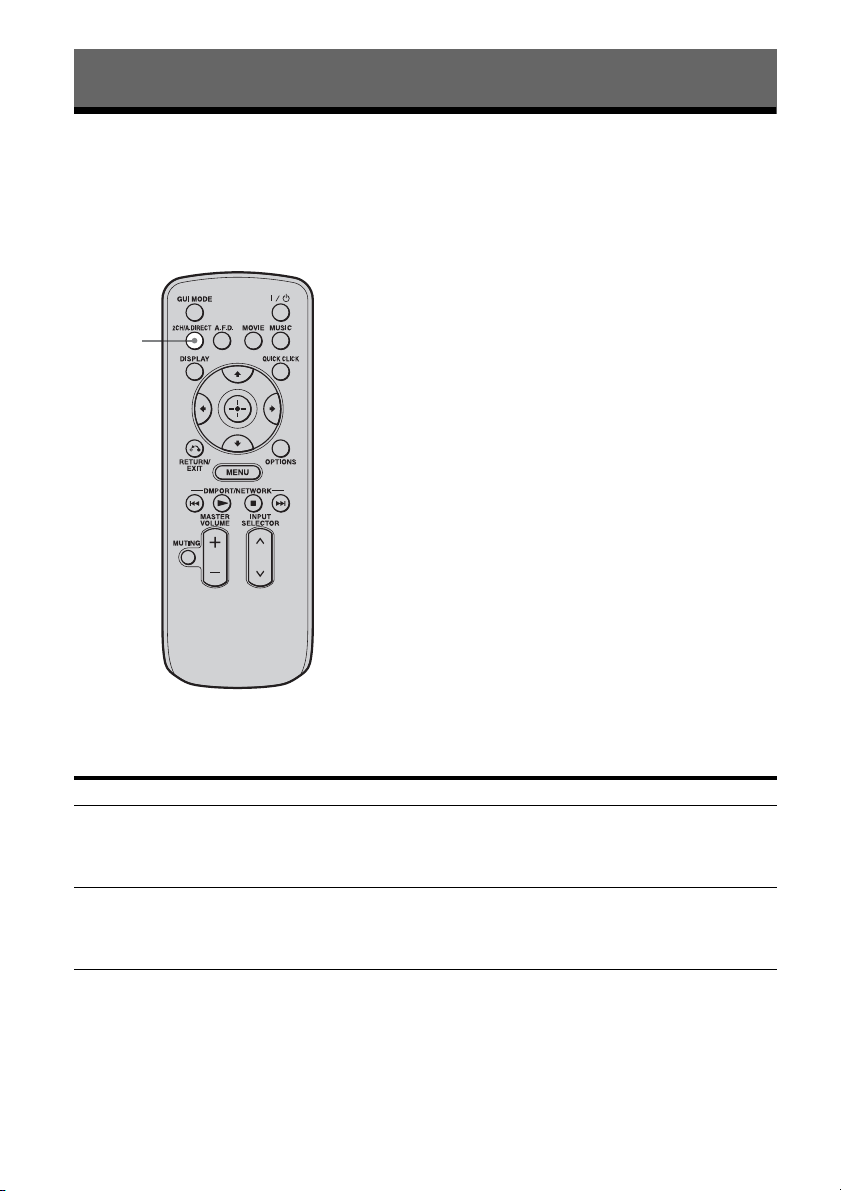
82
GB
Playing back with 2-channel sound
You can switch the output sound to 2-channel sound regardless of the recording formats of the
software you are using, the playback component connected, or the sound field settings of the
receiver.
Press 2CH/A.DIRECT repeatedly to select the 2-channel sound mode of the
sound output you want.
Enjoying Surround Sound
2CH mode Effect
2ch Stereo The receiver outputs the sound from the front left/right speakers only. There is
no sound from the subwoofer.
Standard 2 channel stereo sources completely bypass the sound field processing
and multi-channel surround formats are downmixed to 2 channel.
2ch Analog Direct You can switch the audio of the selected input to 2 channel analog input. This
function enables you to enjoy high quality analog sources.
When using this function, only the volume and front speaker balance can be
adjusted.
2CH/
A.DIRECT
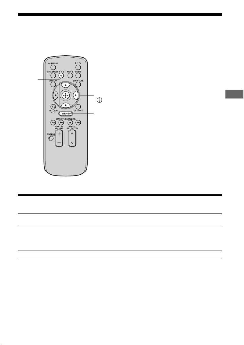
83
GB
Enjoying Surround Sound
Playing back with multi-channel surround
The Auto Format Direct (A.F.D.) mode allows you to listen to higher fidelity sound and select the
decoding mode for listening to a 2 channel stereo sound as multi-channel sound.
Press A.F.D. repeatedly to select the A.F.D. mode you want.
A.F.D. mode Multi-channel
audio after
decoding
Effect
A.F.D. Auto (Detecting
automatically)
Presets the sound as it was recorded/encoded without
adding any surround effects.
Enhanced Surround – You can select the surround sound effect you want. For
details on available surround sound effects and how to
set one, see “Setting a multi-channel surround sound
effect” (page 84).
Multi Stereo (Multi Stereo) Outputs 2 channel left/right signals from all speakers.
A.F.D.
V/v/b,
MENU
84
GB
1 Start playing a sound source
you want to listen to (CD, DVD,
etc.).
2 Press MENU.
The menu is displayed on the TV screen.
3 Press V/v repeatedly to select
“ Settings,” then press or
b.
The Settings menu list appears on the TV
screen.
4 Press V/v repeatedly to select
“Surround,” then press or b.
5 Press V/v repeatedly to select
“Enhanced Sur Mode,” then
press .
The menu for surround sound effect
appears.
6 Press V/v repeatedly to select
the Enhanced Sur Mode you
want, then press .
* You can select “Pro Logic II” when there is no surround back speaker on the Speaker Pattern menu, or you
can select “Pro Logic IIx” when there is a surround back speaker. You cannot select both settings at the same
time.
Setting a multi-channel
surround sound effect
Enhanced Sur Mode Multi-channel
audio after
decoding
Effect
Pro Logic II* 5-channel signals Performs Dolby Pro Logic II mode decoding. A source
recorded in 2 channel format is decoded into 5.1
channels. This setting is ideal for movies encoded in
Dolby Surround. In addition, this mode can reproduce
sound in 5.1 channel system for watching videos of
overdubbed or old movies.
Pro Logic IIx* 7-channel signals Performs Dolby Pro Logic IIx mode decoding. A source
recorded in 2 channel or 5.1 channel format is decoded
into 7.1 channels. This setting is ideal for movies
encoded in Dolby Surround. In addition, this mode can
reproduce sound in 7.1 channel system for watching
videos of overdubbed or old movies.
Neo:6 Cinema 7-channel signals Performs DTS Neo:6 Cinema mode decoding. A source
recorded in 2 channel format is decoded into 7 channels.
Neo:6 Music 7-channel signals Performs DTS Neo:6 Music mode decoding. A source
recorded in 2 channel format is decoded into 7 channels.
This setting is ideal for normal stereo sources such as
CDs.
Neural-THX 7-channel signals Next generation of Neural-THX
®
Surround. In addition
to stereo enhancement processing and pure discrete 5.1
surround sound, now capable of full 360° 7.1 surround
sound playback from Neural-THX
®
Surround encoded
content.

85
GB
Enjoying Surround Sound
Notes
• This function does not work when the multi-
channel input is selected.
• Neural-THX is not effective when DTS-HD
signals with a sampling frequency of 88.2 kHz and
higher are being received.
• This function does not work when Dolby TrueHD
signals with a sampling frequency of 176.4 kHz
and higher are being received.
• The beginning of the sound stream may be dropped
out when Neural-THX processing is turned on or
off.
Tips
• We usually recommend “A.F.D. Auto.”
• You can identify the encoding format of DVD
software, etc., by looking at the logo on the
package.
• Dolby Pro Logic IIx decoding is effective, when
2 channel or 5.1 channel signals are input.
• Neural-THX is effective when 2 channel or
5.1 channel signals are input.
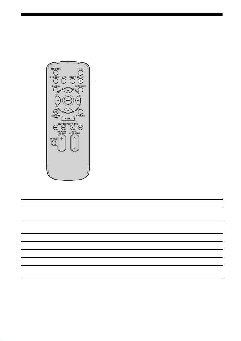
86
GB
Enjoying a surround effect for music
You can take advantage of surround sound simply by selecting one of the receiver’s pre-
programmed sound fields. They bring the exciting and powerful sound of concert halls into your
home.
Press MUSIC repeatedly to select the surround effect you want for music.
Sound field Effect
D.Concert Hall A Uses 3D sound imaging to reproduce the sound characteristics of a concert hall,
which simulates a large sound stage produced by reflectivity.
D.Concert Hall B Uses 3D sound imaging to reproduce the sound characteristics of a concert hall,
which simulates resonant and unique reverberative sound.
Jazz Club Reproduces the acoustics of a jazz club.
Live Concert Reproduces the acoustics of a 300-seat live house.
Stadium Reproduces the feeling of a large open-air stadium.
Sports Reproduces the feeling of sports broadcasting.
Portable Audio Reproduces a clear enhanced sound image from your portable audio device.
This mode is ideal for MP3 and other compressed music.
MUSIC

87
GB
Enjoying Surround Sound
To listen to music through headphones connected to the receiver
To turn off the surround effect for MUSIC
Press 2CH/A.DIRECT or A.F.D.
Notes
• The sound fields for music do not work when the
multi-channel input is selected.
• The sound fields for music do not work when DTS-
HD signals with a sampling frequency of 88.2 kHz
and higher are being received.
• The sound fields for music do not work when
Dolby TrueHD signals with a sampling frequency
of 176.4 kHz and higher are being received.
• If you set up the sound field during DTS 96/24
signal reception, the signal will be played back
only at 48 kHz.
• If you set up the sound field effect while the
receiver is receiving signals with a sampling
frequency of 88.2 kHz and higher, the signals will
always be played back at either 44.1 kHz or
48 kHz.
• When one of the sound fields for music is selected,
no sound is output from the subwoofer if all the
speakers are set to “LARGE” in the Speaker
settings menu. However, the sound will be output
from the subwoofer if the digital input signal
contains L.F.E. signals, or if the front or surround
speakers are set to “SMALL,” the sound field for
movie is selected, or “Portable Audio” is selected.
• If there is any noise present, the noise may be
different depending on the sound field you select.
Sound field Effect
Headphone (2ch) This mode is selected automatically if you use headphones when “2ch Stereo”
mode or A.F.D. mode is selected. Standard 2 channel stereo sources completely
bypass the sound field processing and multi-channel surround formats are
downmixed to 2 channels.
Headphone (Direct) Outputs the analog signals without processing by the tone, sound field, etc.
Headphone (Multi) This mode is selected automatically if you use headphones when the multi-
channel input is selected. Outputs the front analog signals from the MULTI
CHANNEL INPUT jacks.
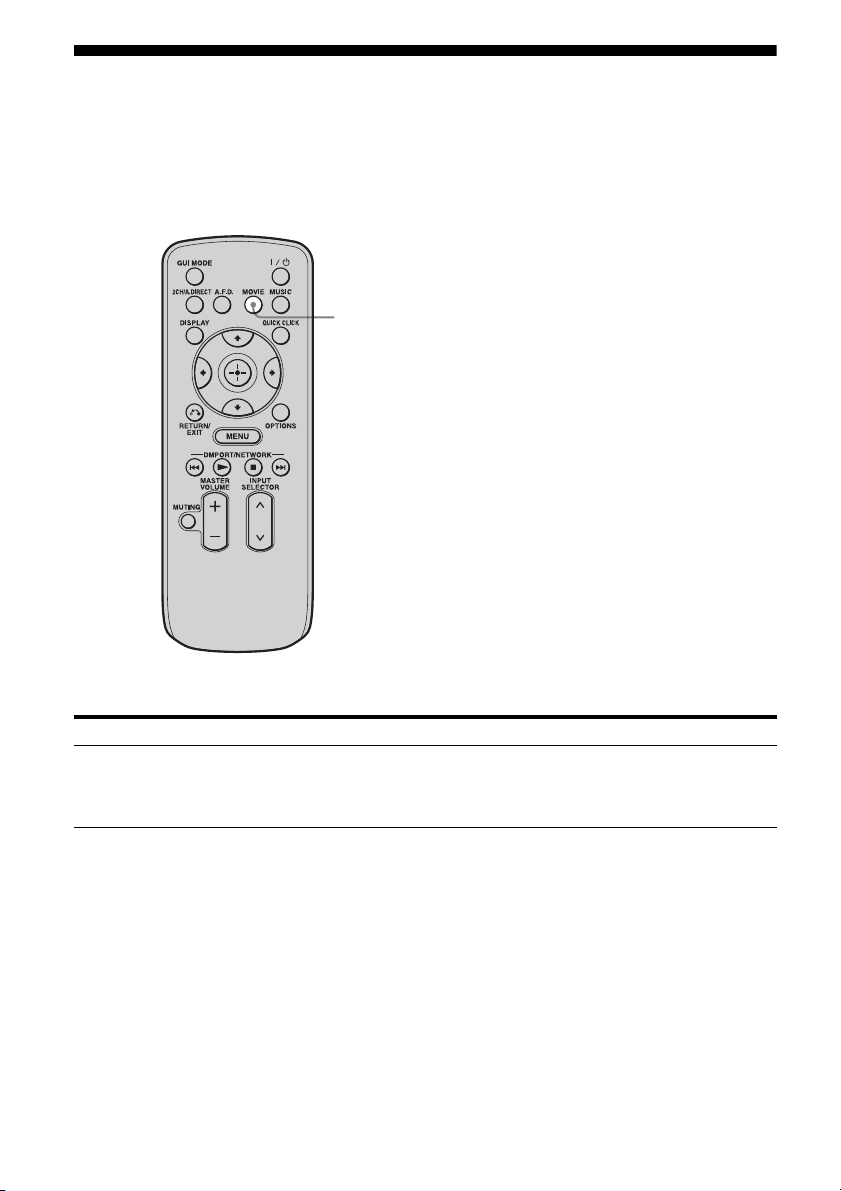
88
GB
Enjoying a surround effect for movies
You can take advantage of surround sound simply by selecting the receiver’s preprogrammed HD-
D.C.S. (HD Digital Cinema Sound) sound field. It brings the exciting and powerful sound of movie
theaters into your home.
For details on HD-D.C.S. technology, see “Glossary” (page 180).
Press MOVIE.
To turn off the surround effect for MOVIE
Press 2CH/A.DIRECT or A.F.D.
Sound field Effect
HD-D.C.S. HD-D.C.S. can realize precisely sound effect on the movies watching through
Blu-ray and DVD software, etc. like how Movie Sound Designers’ intended to
be. You can select the Effect Type for HD-D.C.S. For details, see “Sound Field
Setup” (page 134).
MOVIE

89
GB
Enjoying Surround Sound
Notes
• HD-D.C.S. does not work when the multi-channel
input is selected.
• HD-D.C.S. does not work when DTS-HD signals
with a sampling frequency of 88.2 kHz and higher
are being received.
• HD-D.C.S. does not work when Dolby TrueHD
signals with a sampling frequency of 176.4 kHz
and higher are being received.
• If you set up the sound field during DTS 96/24
signal reception, the signal will be played back
only at 48 kHz.
• If you set up the sound field effect while the
receiver is receiving signals with a sampling
frequency of 88.2 kHz and higher, the signals will
always be played back at either 44.1 kHz or
48 kHz.
• If there is any noise present, the noise may be
different depending on the sound field you select.
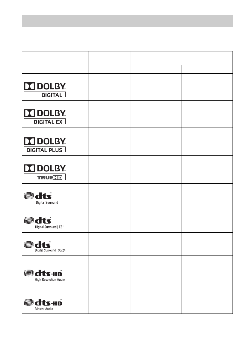
90
GB
Digital audio formats that this receiver can decode depend on digital audio input jacks for the
components connected.
This receiver supports the following audio formats.
Digital audio formats supported by the receiver
Audio format
Maximum number
of channels
Connection of the playback component and
the receiver
COAXIAL/OPTICAL HDMI
Dolby Digital
5.1ch
aa
Dolby Digital EX
6.1ch
aa
Dolby Digital Plus
a)
7.1ch
× a
Dolby TrueHD
a)
7.1ch
× a
DTS
5.1ch
aa
DTS-ES
6.1ch
aa
DTS 96/24
5.1ch
aa
DTS-HD
High Resolution Audio
a)
7.1ch
× a
DTS-HD
Master Audio
a) b)
7.1ch
× a

91
GB
Enjoying Surround Sound
a)Audio signals are output in another format if the playback component does not correspond to the format. For
details, refer to the operating instructions of the playback component.
b)Signals with a sampling frequency of 176.4 kHz and higher are played back at 96 kHz or 88.2 kHz.
DSD
a)
5.1ch
× a
Multi channel Linear PCM
a)
7.1ch
× a
Audio format
Maximum number
of channels
Connection of the playback component and
the receiver
COAXIAL/OPTICAL HDMI

92
GB
About the network
functions of the receiver
• The home network function of the receiver
supports the DLNA (Digital Living Network
Alliance) standard.
You can also enjoy content (music, photos,
and videos) which have been stored on a
DLNA-compliant device (DLNA
CERTIFIED™ Products) that has an
authorized DLNA logo displayed on the
device.
• With an Internet connection, you can listen
to Rhapsody and SHOUTcast and upgrade
the firmware of the receiver. Rhapsody is
only available in the US.
About DLNA
DLNA (Digital Living Network Alliance) is a
standards organization made up of
manufacturers of various products, such as
computers, AV components, and mobile
computing devices which exchange content
(music, photos, and videos). DLNA decides
upon standards and publishes an authorized
logo to be displayed on devices which support
DLNA standards.
Using Network Features
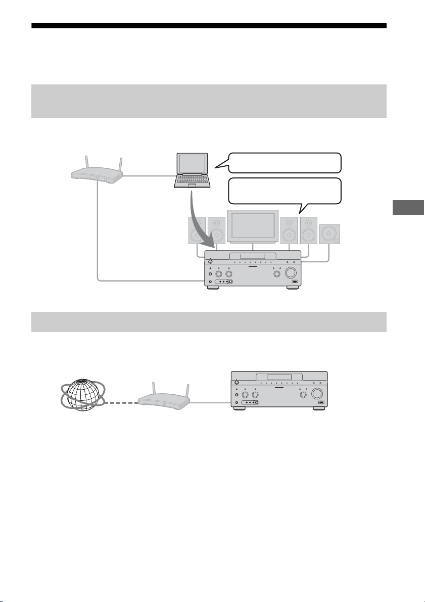
93
GB
Using Network Features
What you can do with the home network function
You can do the following using the network function of the receiver.
You can play back music, photos, and videos stored on other devices such as a computer on your
home network using this receiver (page 96).
You can listen to Rhapsody or SHOUTcast using the receiver (page 98, 101). Rhapsody is only
available in the US.
Playing back content (music, photos, and videos) on devices on a
home network
Listening to Rhapsody or SHOUTcast over the Internet
Delivers content
Plays back content
Computer
STR-DA5500ES
STR-DA5500ESInternet
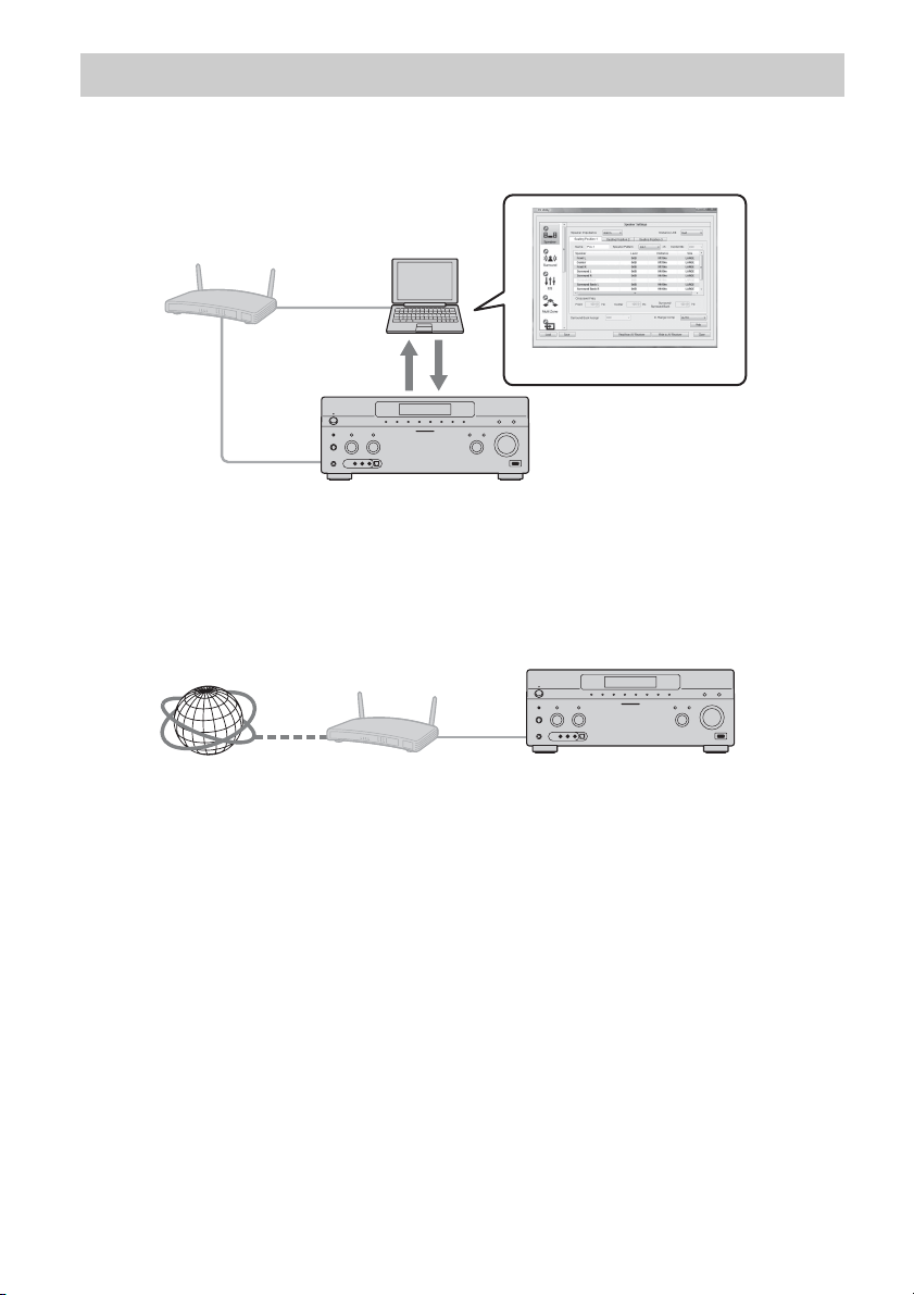
94
GB
Changing the settings using a computer
You can change the settings of the receiver using a computer on your home network (page 103).
Firmware update
You can update the firmware of the receiver over the Internet.
A) Update the firmware directly over the Internet (page 146)
Other features
Computer
STR-DA5500ES
ES Utility application software
STR-DA5500ES
Internet
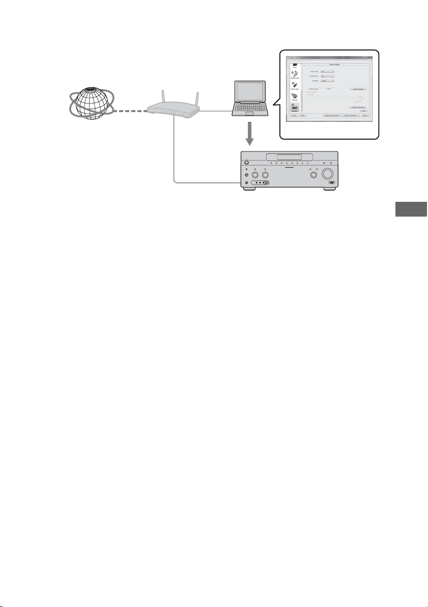
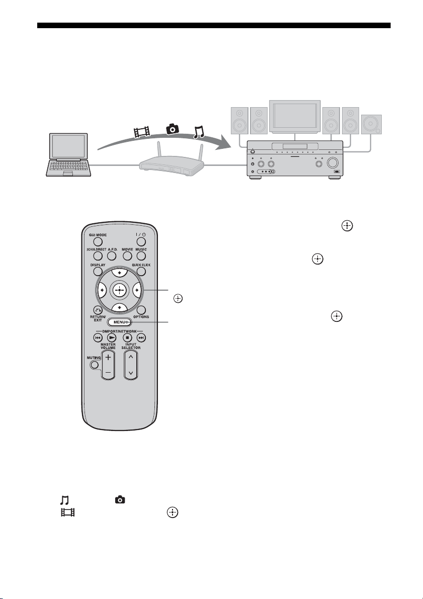
96
GB
Enjoying content stored on the server
A server is a device which delivers content (music, photos, and videos) to a DLNA device on a
home network.
You can play back music, photos, and videos stored on the server using the receiver.
1 Press MENU.
The menu is displayed on the TV screen.
2 Press V/v repeatedly to select
“ Music,” “ Photo,” or
“ Video,” then press or b.
3 Press V/v repeatedly to select
“Server,” then press .
The server list appears on the TV screen.
4 Press V/v and to select the
server which holds the content
you want to play.
The content list appears on the TV screen.
5 Press V/v/B/b and
repeatedly to select content
you want to play from the
content list.
The playback screen appears on the TV
screen, and content you selected is played
back.
Computer STR-DA5500ES
V/v/B/b,
MENU
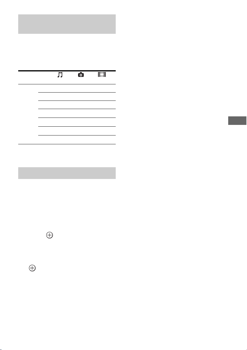
97
GB
Using Network Features
You can enjoy content on the server by using
the following buttons on the multifunction
remote.
Press AMP to operate the receiver using the
remote.
* This button may not work depending on the
connected server or the content type.
You can select the playback mode of the Music
category.
1 Press OPTIONS while listening
to the music content.
2 Press V/v repeatedly to select
“Repeat,” or “Shuffle,” then
press .
3 Press V/v repeatedly to select
the mode you want to select
from the following, then press
.
x Repeat
Plays one or all the tracks repeatedly.
•Off
Deactivates the repeat play mode.
•One
Plays one track repeatedly.
•All
Plays all the tracks repeatedly.
x Shuffle
Plays all the tracks in random order.
•Off
Deactivates the shuffle play mode.
•On
Activates the shuffle play mode.
Using the multifunction remote
to play back content
Content
Type Music Photo Video
Remote
button
Nz z z
xz z z
Xz z z
>z z
.z z
Mz* z*
mz* z*
Selecting the playback mode

98
GB
Listening to Rhapsody
You can enjoy the Rhapsody Digital Music
Service, without turning on a computer, by
connecting your receiver to the internet.
Rhapsody is only available in the US.
Rhapsody Digital Music Service
Play all the music you want with Rhapsody
®
Thousands of artists. Millions of songs.
Rhapsody is the critically-acclaimed digital
music service that gives you unlimited access
to a massive music catalog of millions of songs
and thousands of artists. You’ll also get
exclusive content, personalized
recommendations, DJ/ad-free listening on
“Rhapsody Channels” and more.
Try Rhapsody Now – Free 30 day Trial
For more information go to:
www.rhapsody.com/sonystr
Before using the Rhapsody Digital Music
Service, it is necessary to register an account
using your computer.
Refer to www.rhapsody.com/sonystr for
details.
Sign in using your account on the receiver.
1 Press MENU.
The menu is displayed on the TV screen.
2 Press V/v repeatedly to select
“ Settings,” then press or
b.
3 Press V/v repeatedly to select
“Network,” then press or b.
4 Press V/v repeatedly to select
“Rhapsody Account,” then
press .
The confirmation screen for account input
appears on the TV screen.
5 Press B/b repeatedly to select
“Yes,” then press .
The account input screen appears on the
TV screen.
6 Press V/v to select the user
name box, then press .
The soft keyboard appears on the TV
screen.
7 Press V/v/B/b and to select
a character one by one to enter
your user name.
8 Press V/v/B/b repeatedly to
select “Finish,” then press .
9 Press V/v repeatedly to select
the password box, then press
.
V/v/B/b,
MENU
OPTIONS
Setting an account
99
GB
Using Network Features
10Press V/v/B/b and to select
a character one by one to enter
your password.
11Press V/v/B/b repeatedly to
select “Finish,” then press .
12Press V/v repeatedly to select
“Finish,” then press .
Note
Repeat the process again from step 6 if the sign in
fails.
To delete an account
1
Press MENU.
The menu is displayed on the TV screen.
2 Press V/v repeatedly to select
“ Settings,” then press or b.
3 Press V/v repeatedly to select
“Network,” then press or b.
4 Press V/v repeatedly to select
“Rhapsody Account,” then press .
5 Press OPTIONS to select “Remove
Account,” then press .
6 Press B/b repeatedly to select “Yes,”
then press .
The user name and the password are
deleted.
You can select the channel you want to listen
using the Rhapsody Channels list.
1 Press MENU.
The menu is displayed on the TV screen.
2 Press V/v repeatedly to select
“ Rhapsody,” then press
or b.
3 Press V/v repeatedly to select
“Rhapsody Channels,” then
press .
4 Press V/v/B/b repeatedly to
select the channel you want to
listen to, then press .
The reception screen appears on the TV
screen and the channel you selected is
received.
Note
You can listen to only the same channel in both the
main zone and the 2nd zone.
Priority is given to the channel which has most
recently been selected, even if other channel is
currently being selected in one of zones.
The Music Guide displays a variety of music
selections to sample, including top tracks and
artists, and recommendations.
Select genre names, charts, and new releases
anywhere in the Music Guide pages to browse
more.
1 Press MENU.
The menu is displayed on the TV screen.
2 Press V/v repeatedly to select
“ Rhapsody,” then press
or b.
3 Press V/v repeatedly to select
“Rhapsody Music Guide,” then
press .
4 Press V/v repeatedly to select
“Genres,” “Charts,” “New
Releases,” or “Rhapsody
Recommends,” then press .
Selecting the channel from the
Rhapsody Channels list
Selecting the track using Music
Guide
continued

100
GB
5 Press V/v/B/b to select the
track you want to listen to from
the list, then press .
The playback screen appears on the TV
screen and the track you selected is
played back.
Note
You can listen to only the same track in both the
main zone and the 2nd zone.
Priority is given to the track which has most recently
been selected, even if other track is currently being
selected in one of zones.
You can search for a track, album, or artist
using the search function.
1 Press MENU.
The menu is displayed on the TV screen.
2 Press V/v repeatedly to select
“ Rhapsody,” then press
or b.
3 Press V/v repeatedly to select
“Search,” then press .
4 Press V/v repeatedly to select
“Artists,” “Albums,” or
“Tracks” you want to search for,
then press .
The soft keyboard appears on the TV
screen.
5 Press V/v/B/b and to select
a character one by one to enter
the title or name you want to
search for.
6 Press V/v/B/b to select
“Finish,” then press .
Wait until the search result is displayed.
7 Press b to select the search
results.
8 Press V/v/B/b repeatedly to
select the track you want to
listen to from the search result,
then press .
The playback screen appears on the TV
screen, and track you selected is played
back.
Note
You can listen to only the same track in both the
main zone and the 2nd zone.
Priority is given to the track which has most recently
been selected, even if other track is currently being
selected in one of zones.
You can register your favorite track, album, or
channel in “My Library” while playing back
the track or during reception.
You can select the track, album or channel that
you registered in “My Library” from “My
Artists,” “My Albums,” “My Genres,” “My
Tracks,” “My Playlists,” or “My Channels.”
1 Press OPTIONS while a track is
playing back or you are
selecting a channel.
2 Press V/v repeatedly to select
“Add track to My Library,” “Add
album to My Library,” or “Add
channel to My Library,” then
press .
The track, album, or channel you chose
will be registered in “My Library.”
To remove a track, album, or
channel you registered
You can remove a track, album, or channel you
registered in “My Library.”
1 Press OPTIONS while a track is playing
back or you are selecting a channel.
Searching for a track, album, or
artist you want to listen to
Registering your favorite track,
album, or channel
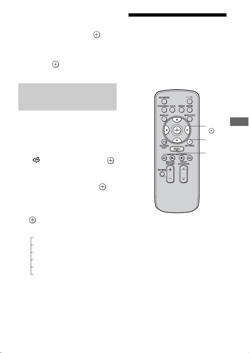
101
GB
Using Network Features
2 Press V/v repeatedly to select “Delete
album from My Library,” “Delete track
from My Library,” or “Delete channel
from My Library,” then press .
The confirmation screen of deletion
appears on the screen.
3 Press B/b repeatedly to select “Yes,”
then press .
The deletion is completed.
You can select a track, playlist or channel you
registered in “My Library.”
1 Press MENU.
The menu is displayed on the TV screen.
2 Press V/v repeatedly to select
“ Rhapsody,” then press
or b.
3 Press V/v repeatedly to select
“My Library,” then press .
4 Press V/v/B/b to select the
track you want to listen to using
the My Library list, then press
.
*The number of lists displayed on the screen
depends on the status of the Rhapsody Digital
Music Service you are using.
The playback screen appears on the TV
screen and the track you selected is
played back.
Listening to SHOUTcast
SHOUTcast is a digital audio streaming
technology-based radio service.
SHOUTcast is a directory of internet radio
stations, allowing users to access thousands of
free online radio stations from DJs and
broadcasters around the world.
Refer to http://www.shoutcast.com for details.
Selecting a track, playlist or
channel you registered for My
Library
My Library list
My Artists > artist(s)
*
> albums(s)
*
> track(s)
*
My Albums > album(s)
*
> track(s)
*
My Genres > genre(s)
*
> artist(s)
*
> album(s)
*
> track(s)
*
My Tracks > track(s)
*
My Playlists > playlist(s)
*
> track(s)
*
My Channels > channel(s)
*
V/v/B/b,
MENU
OPTIONS
102
GB
1 Press MENU.
The menu is displayed on the TV screen.
2 Press V/v repeatedly to select
“ SHOUTcast,” then press
or b.
3 Press V/v repeatedly to select
“Preset List,” “0-9,” or A to Z,
then press .
4 Press V/v repeatedly to select
the genre you want to listen to,
then press .
5 Press V/v/B/b to select the
station you want to listen to,
then press .
The reception screen appears on the TV
screen, and the station you selected is
received.
Notes
• When the number of stations is large, up to 100
stations can be displayed (in order) on this receiver.
• The audio supplied in a format that is not supported
by this receiver does not appear on the list.
• You can listen to only the same station in both the
main zone and the 2nd zone.
Priority is given to the station which has most
recently been selected, even if other station is
currently being selected in one of zones.
You can register your favorite SHOUTcast
stations on the receiver.
1 Press OPTIONS while listening
to the radio station.
2 Press to select “Add to
Preset List.”
The preset number list appears on the TV
screen.
3 Press V/v repeatedly to select
the preset number you want to
preset, then press .
Note
If you select a list number for which a station has
already been registered, the previously registered
station will be overwritten.
Tip
You can register one station for different list
numbers.
To return to the previous screen
Press RETURN/EXIT O.
You can select your favorite stations from
among the stations you registered.
1 Press MENU.
The menu is displayed on the TV screen.
2 Press V/v repeatedly to select
“ SHOUTcast,” then press
or b.
3 Press V/v repeatedly to select
“Preset List,” then press .
4 Press V/v repeatedly to select
the preset number station you
want to listen to, then press .
The reception screen appears on the TV
screen, and the station you selected is
received.
Selecting a SHOUTcast station
Presetting favorite stations
Selecting preset stations
103
GB
Using Network Features
Features of the ES Utility
application software
You can check the settings of the receiver, and
adjust those settings using your computer, as
well as using the receiver, after installing the
ES Utility application software provided on
the CD-ROM supplied with the receiver.
The following settings cannot be set using the
computer with the ES Utility application
software.
• Auto Calibration
–Quick Setup
–Enhanced Setup
• Speaker
–Test Tone
• Multi Zone
– Zone Power ON/OFF
– Zone Input Change
– Zone Volume Adjust
Operating System
Windows XP Home Edition/Professional/
Media Center Edition 2005 (SP3, 32 bit)
Windows Vista Home Basic/Home Premium/
Business/Ultimate (SP1, 32 bit/64 bit)
Computer
CPU: Celeron, Pentium III or higher
Clock Speed: 1 GHz or higher
RAM: 512 MB or more
HDD: 20 MB or more free disk space
(280 MB free disk space is required when
.NET Framework 2.0 is not installed.)
Monitor: 1024 × 768, High Color
(65536 colors)
Network: 100Base-TX or higher
1 Turn on your computer and
login as an administrator.
2 Insert the supplied CD-ROM
into the CD-ROM drive of your
computer.
The installation launcher starts
automatically, then a Software Setup
screen appears on the screen.
If the installation launcher does not start
automatically, double-click
“SetupLauncher.exe” on the disc.
3 Install the ES Utility application
software following the
instructions given in the
message on the screen.
You can update the receiver firmware using the
ES Utility application software provided on
the CD-ROM supplied with the receiver. Refer
to the HELP of the ES Utility for details on
operations of the ES Utility.
1 Download the update program
from the support website on the
computer to which you
installed the ES Utility.
2 Press MENU.
The menu is displayed on the TV screen.
System Requirements
Installing the ES Utility
application software on a
computer
Updating the receiver firmware
using the ES Utility
CD-ROM (ES Utility
application software)
(supplied)
continued

104
GB
3 Press V/v repeatedly to select
“ Settings,” then press or
b.
4 Press V/v repeatedly to select
“System,” then press or b.
5 Press V/v repeatedly to select
“System Update,” then press
.
6 Press V/v repeatedly to select
“PC Update,” then press .
A confirmation screen appears on the TV
screen.
7 Press V/v repeatedly to select
“Start,” then press .
The status of waiting for the data from the
PC is displayed on the TV screen.
8 Click “System” in the ES Utility
window on the computer
screen, then click “Browse...”
and specify the path of the
update program, and click
“Start Update.”
Receiver updating starts.
When updating complete, the receiver
will restart automatically.
Notes
• Do not turn the receiver off or disconnect the
network cable during firmware updating. It may
cause a malfunction.
• It may take 30 minutes for the firmware updating to
complete.
To check the HELP
When you want to check the HELP of the ES
Utility application software,
click [Start] – [All Programs] – [ES Utility] –
[Help for ES Utility], in that order.

105
GB
Using Multi-zone Features
What you can do with the
Multi-zone function
You can enjoy images and sounds from a
component connected to the receiver in a zone
other than the main zone. For example, you
can watch the DVD in the main zone and listen
to the CD in zone 2 or zone 3.
When using an IR repeater (not supplied), you
can operate both a component in the main zone
and Sony receiver in zone 2 or zone 3 from
zone 2 or zone 3.
Use the multifunction remote in zone 2 or
zone 3. You cannot use the simple remote in a
zone (zone 2 or zone 3) other than the main
zone.
To operate the receiver from
zone 2 or zone 3
You can operate the receiver without pointing
the remote toward the IR repeater of the
receiver if you connect an IR repeater (not
supplied) to the IR REMOTE jack.
Use an IR repeater when you install the
receiver in a place where signals from the
remote cannot reach.
Using Multi-zone Features
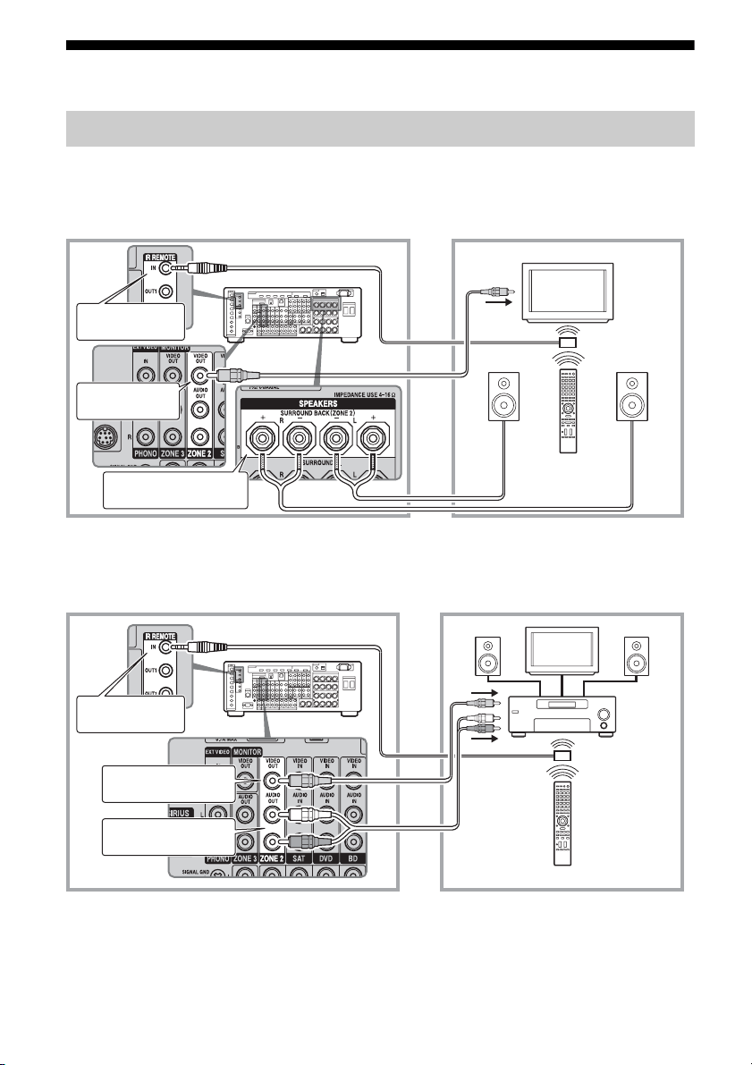
106
GB
Making a multi-zone connection
1 Outputs sound from speakers in zone 2 using the SURROUND
BACK SPEAKERS terminals of the receiver.
2 Outputs sound from speakers in zone 2 using the receiver and
another amplifier.
A IR repeater (not supplied)
B Speakers
C Sony Amplifier/Receiver
* You can also connect to the COMPONENT VIDEO ZONE 2 OUT jack.
1:Zone 2 connections
Main zone Zone 2
TV
monitor
ZONE 2 VIDEO
OUT*
B
STR-DA5500ES
B
SURROUND BACK
SPEAKERS
A
Multifunction remote
IR REMOTE IN
Main zone Zone 2
TV
monitor
ZONE 2 AUDIO OUT
A
BB
C
STR-DA5500ES
Multifunction remote
IR REMOTE IN
ZONE 2 VIDEO OUT*
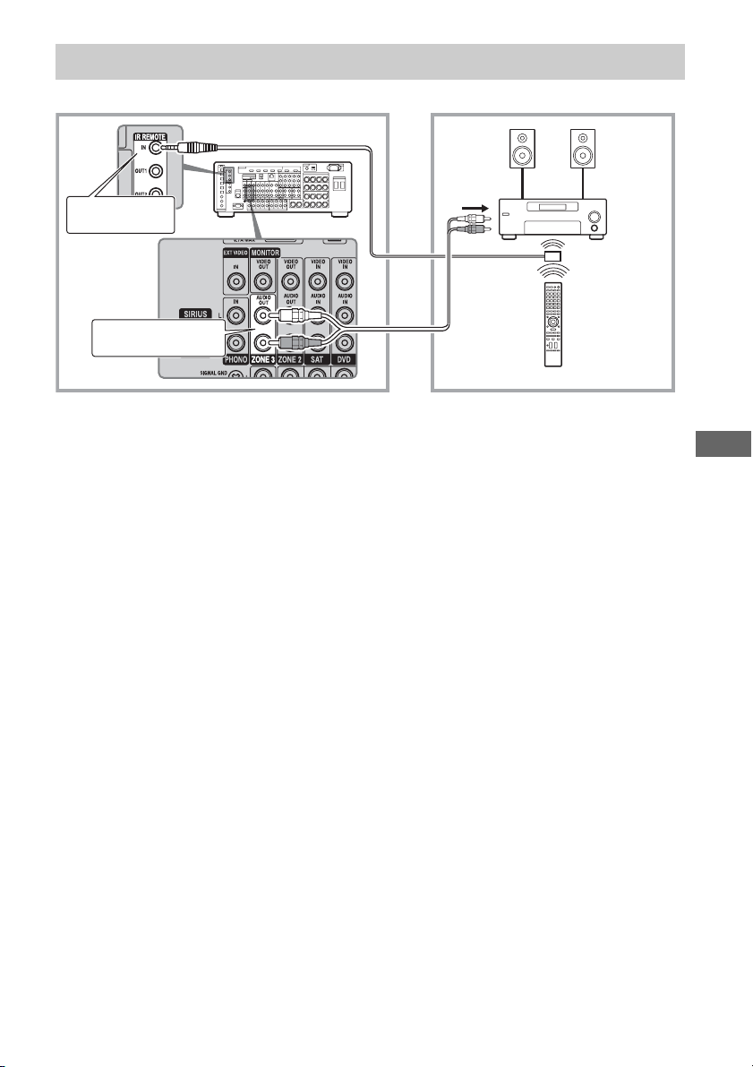
107
GB
Using Multi-zone Features
2:Zone 3 connections
BB
C
STR-DA5500ES
Main room Zone 3
A IR repeater (not supplied)
B Speakers
C Sony Amplifier/Receiver
Multifunction remote
A
IR REMOTE IN
ZONE 3 AUDIO OUT
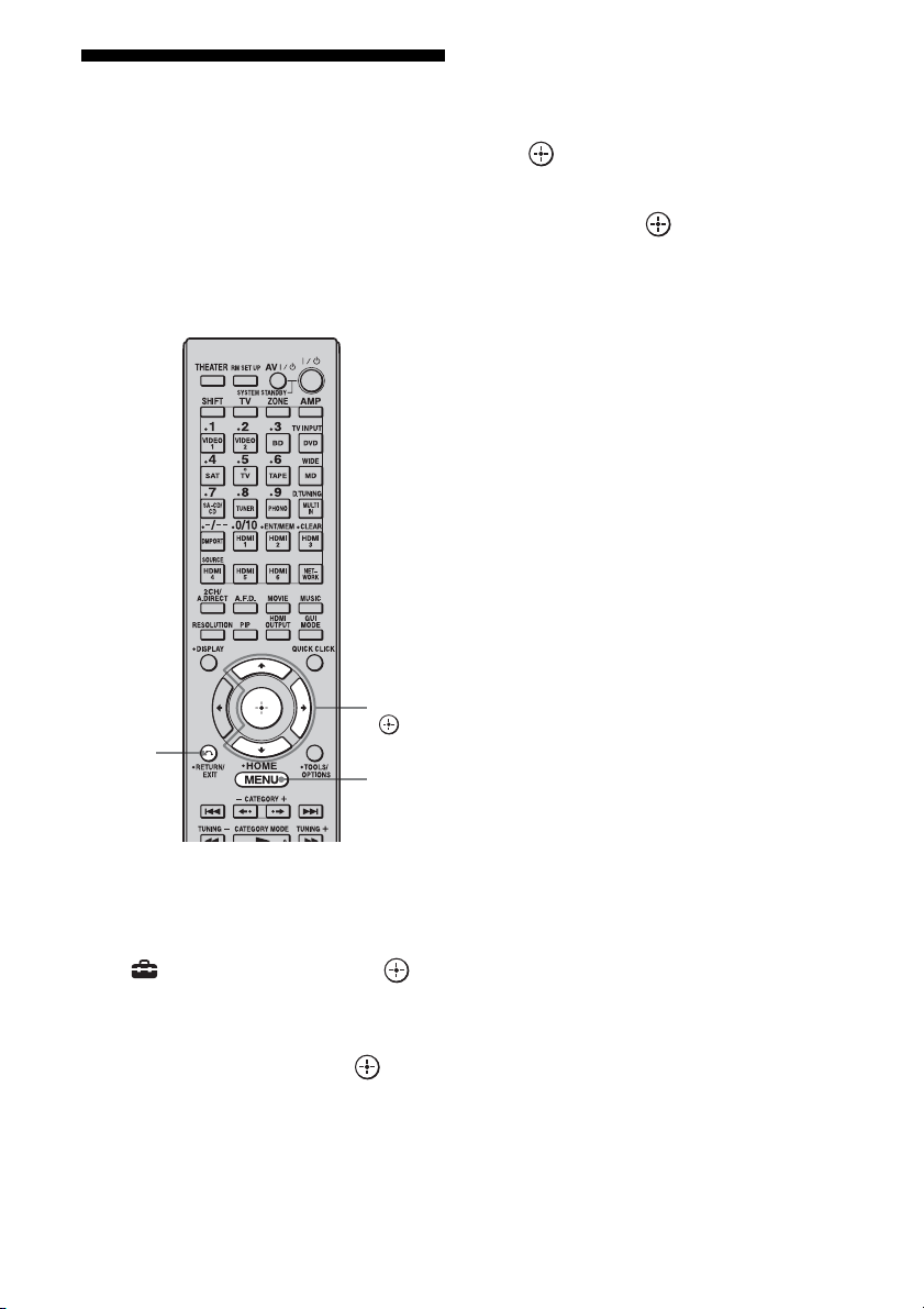
108
GB
Setting the speakers in
zone 2
When the speakers in zone 2 are connected to
the SURROUND BACK SPEAKERS
terminals of the receiver (page 106), make the
setting so that the sound selected in zone 2 is
output from the speakers connected to the
SURROUND BACK SPEAKERS terminals.
1 Press MENU.
The menu is displayed on the TV screen.
2 Press V/v repeatedly to select
“ Settings,” then press or
b.
3 Press V/v repeatedly to select
“Speaker,” then press or b.
4 Press V/v to select “Speaker
Pattern,” to select the pattern
that has no surround back
speakers.
5 Press RETURN/EXIT O.
6 Press V/v repeatedly to select
“Sur Back Assign,” then press
.
7 Press V/v to select “ZONE2,”
then press .
To exit the menu
Press MENU.
RETURN/
EXIT O
V/v/b,
MENU
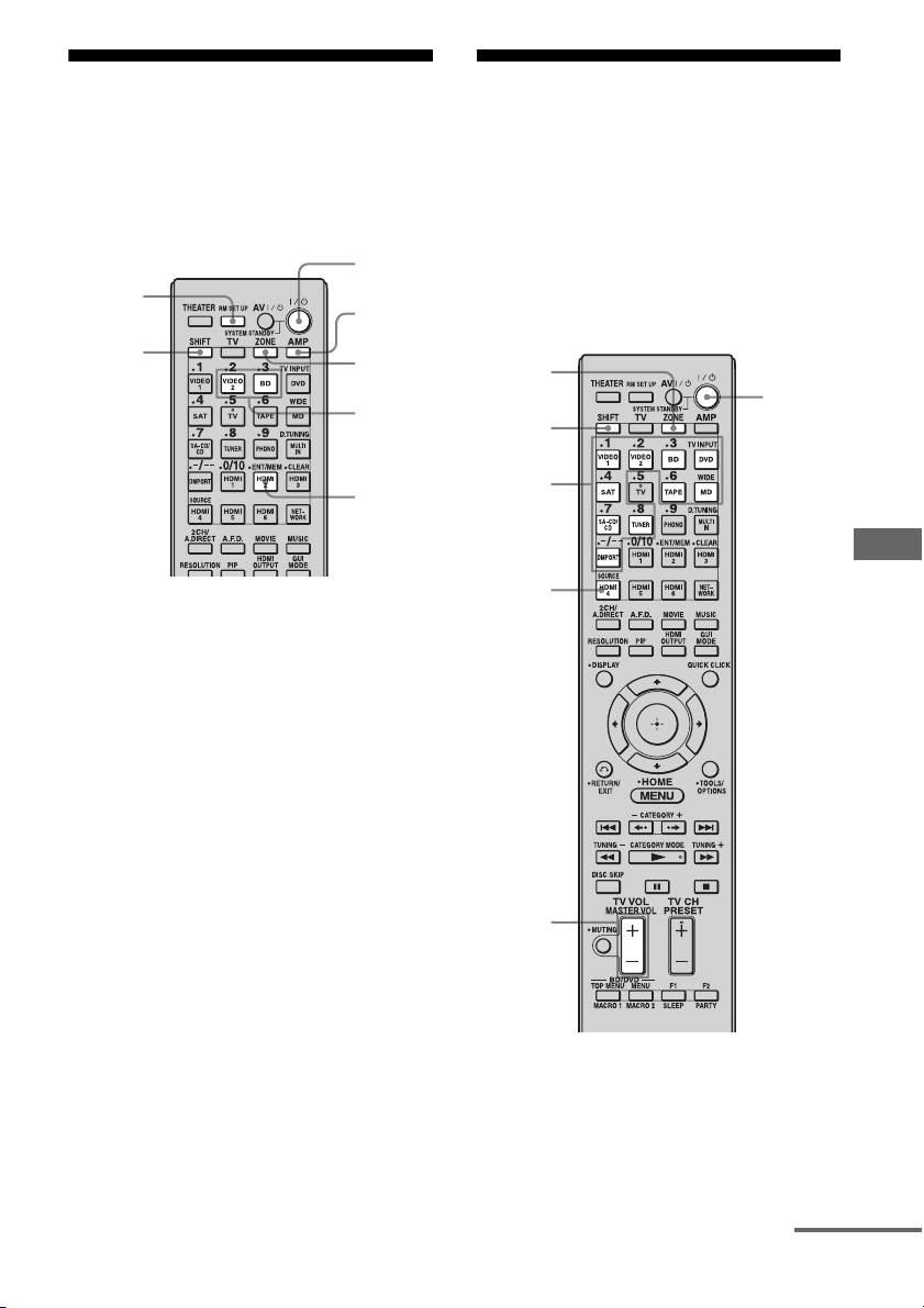
109
GB
Using Multi-zone Features
Switching the zone
setting of the remote
The remote commander is initially set to be
used in zone 2. If you want to use it in zone 3,
switch the zone setting of the remote.
1 Press ?/1 while pressing RM
SET UP.
The AMP and ZONE buttons flash.
2 Press ZONE.
The AMP button goes off, the ZONE
button keeps flashing and the SHIFT
button lights up.
3 Press the numeric button 2 for
the zone 2, or 3 for the zone 3
while the ZONE button is
flashing.
The ZONE button lights up.
4 Press ENT/MEM.
The ZONE button flashes twice and the
remote switches to zone 2 or zone 3
mode.
Operating the receiver
from another zone
(ZONE 2/ZONE 3 operations)
The following operations are described for
connecting an IR repeater and operating the
receiver in zone 2 or zone 3. When an IR
repeater is not connected, use this receiver in
the main zone.
1 Turn on the main receiver (this
receiver) and the amplifier in
zone 2 or zone 3.
ZONE
AMP
2, 3
ENT/
MEM
SHIFT
RM SET
UP
?/1
ZONE
?/1
MASTER
VOL
Input
buttons
SOURCE
SHIFT
continued
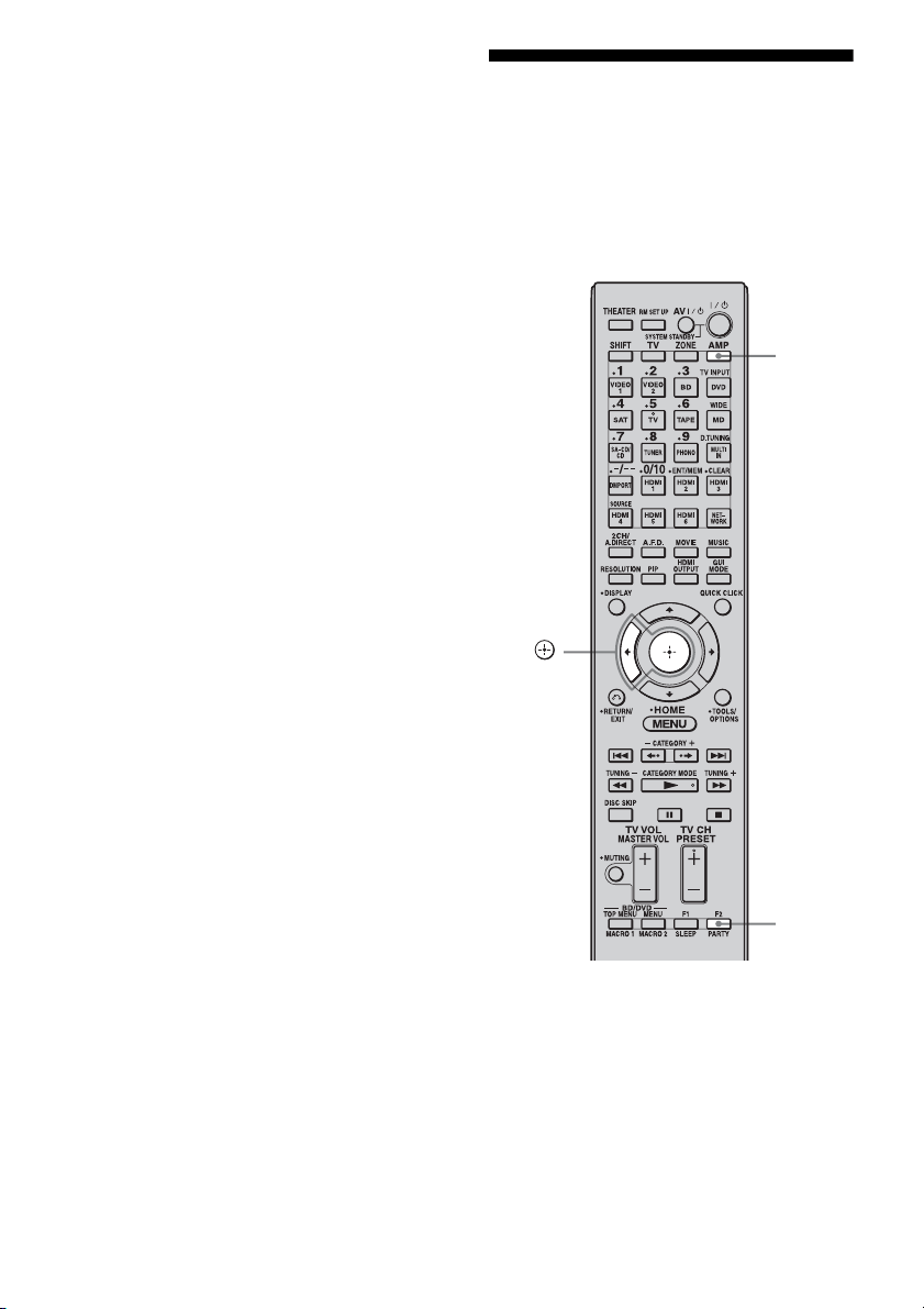
110
GB
2 Press ZONE.
The remote switches to zone 2 or zone 3.
Change the zone setting of the remote to
zone 2 or zone 3 in advance (page 109).
3 Press ?/1.
The zone function is activated.
4 Press one of the input buttons
on the remote to select the
source signals you want to
output.
For zone 2, analog video and audio
signals are output. For zone 3, only
analog audio signals are output. When
you select SOURCE, the signals of the
current input are output.
5 Adjust to a suitable volume.
• In the case of illustration 1-1
(page 106), adjust the volume using
MASTER VOL +/– on the remote.
• In the case of illustration 1-2
(page 106), adjust the volume using the
receiver in zone 2 or zone 3.
To finish the zone 2/zone 3
operation
Press ?/1 after pressing ZONE.
Tips
• Even when this receiver is standby mode (press
?/1 on the remote to turned off this receiver), the
receiver in zone 2 or zone 3 remains turned on. To
turn off all receivers, press ?/1 and AV ?/1 on the
multifunction remote at the same time (SYSTEM
STANDBY).
• Only signals from components connected to the
analog input jacks are output through the ZONE 2
or ZONE 3 jacks. No signals are output from
components connected to only the digital input
jacks.
• When SOURCE is selected, the signals input to the
MULTI CHANNEL INPUT jacks are not output
from the ZONE 2 OUT or ZONE 3 OUT jacks
even when the multi-channel input is selected. The
analog audio signals of the current function are
output.
Listening to the same
music in different zone
(Party Mode)
You can enjoy listening to the same music in
different zone.
1 Start playback in the main zone.
2 Press AMP.
3 Press PARTY.
The party mode screen appears on the TV
screen.
PA RTY
B,
AMP

111
GB
Using Multi-zone Features
4 Press B to select “Start,” then
press .
The same sound of the input selected in
main zone is output in the zone selected in
party mode (page 138).
To exit the party mode
Select other input in zone 2 or zone 3.
See “Operating the receiver from another zone
(ZONE 2/ZONE 3 operations)” (page 109) for
details of the operation of zone2 /zone 3.

112
GB
Using “BRAVIA” Sync
features
“BRAVIA” Sync is compatible with a Sony
TV, Blu-ray Disc/DVD player, AV amplifier,
etc., that is equipped with the Control for
HDMI function.
By connecting Sony components that are
compatible with the “BRAVIA” Sync with a
HDMI cable (not supplied), operation is
simplified as below:
– One-Touch Play (page 114)
– System Audio Control (page 114)
– System Power-Off (page 115)
– Theater Mode Sync (page 115)
– 24p Auto Sound Sync (page 115)
Control for HDMI is a mutual control function
standard used by HDMI CEC (Consumer
Electronics Control) for HDMI (High-
Definition Multimedia Interface).
The Control for HDMI function
does not work in the following
cases:
• When you connect the receiver to a
component which is not correspond with
Sony Control for HDMI function.
• When you connect the receiver and
components using other than HDMI
connection.
• The Control for HDMI function does not
work on a component connected to the
HDMI OUT B jack of the receiver.
We recommend that you connect the receiver
to products featuring “BRAVIA” Sync.
Note
Depending on the connected component, the
Control for HDMI function may not work. Refer to
the operating instructions of the component.
To use the “BRAVIA” Sync, turn the Control
for HDMI function on for both the receiver
and the connected component. The receiver is
compatible with the “Control for HDMI-Easy
Setting” function.
When your TV is compatible
with the “Control for HDMI-Easy
Setting” function
When you connect a Sony TV with the
“Control for HDMI-Easy Setting” function,
the Control for HDMI function of the receiver
can be turned on simultaneously by turning the
Control for HDMI function of the TV on.
1 Make sure that the receiver, TV, and
playback components are connected
using an HDMI cable (not supplied).
(The respective components must be
compatible with the Control for HDMI
function.)
2 Turn on the receiver, TV and playback
components.
3 Turn the Control for HDMI function of
the TV on.
The Control for HDMI function of the
receiver and all the connected components
are simultaneously turned on. During
setup, “SCANNING” appears in the
display window of the receiver, and once
setting is completed, “COMPLETE” will
appear. Wait until the setup is complete.
For details on setup of the TV, refer to the
operating instructions of your TV.
Using Other Features
What is “BRAVIA” Sync?
Preparing for the “BRAVIA”
Sync
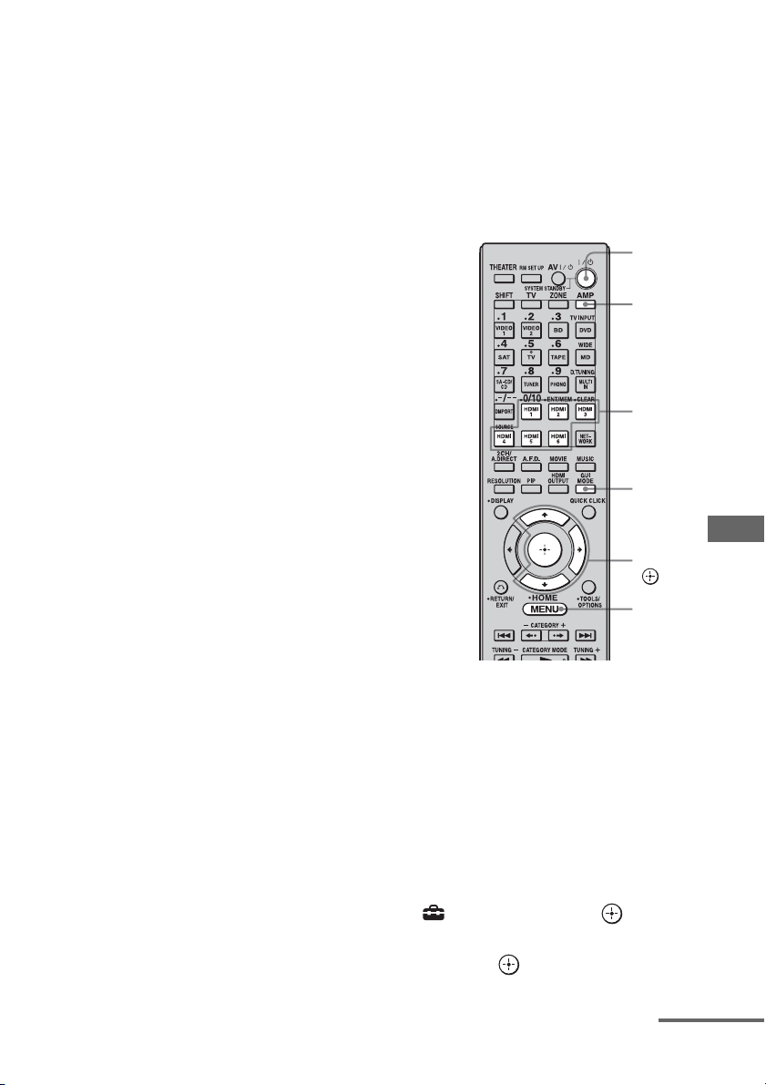
113
GB
Using Other Features
Notes
• When you pull out the HDMI cable or change the
connection, perform the steps given in “When your
TV is compatible with the “Control for HDMI-
Easy Setting” function” (page 112) or “When your
TV is not compatible with the “Control for HDMI-
Easy Setting” function.”
However, you do not need to perform these steps
when you use an HDMI IN 1, IN 2, or IN 6 jack.
• When you assign the component video input to the
HDMI input using the Input Assign function, you
cannot set “Control for HDMI” to “ON.”
• While “Control for HDMI-Easy Setting” is being
set, you cannot use functions such as One-Touch
Play or System Audio Control.
• When you set up the receiver using the “Control for
HDMI-Easy Setting” from a TV, turn on the TV,
the receiver and the playback components
beforehand.
• When you set up the receiver using the “Control for
HDMI-Easy Setting” from a TV, before you make
the “Control for HDMI-Easy Setting” function
effective, make the Control for HDMI function of
the components that are not compatible with the
“Control for HDMI-Easy Setting” function
effective.
When your TV is not compatible
with the “Control for HDMI-Easy
Setting” function
Turn the Control for HDMI function of the
receiver and the connected component on
individually.
Use the multifunction remote for this
operation. This operation cannot be performed
using the simple remote.
1 Perform the steps given in “When your
TV is compatible with the “Control for
HDMI-Easy Setting” function”
(page 112).
2 Press AMP.
The receiver can be operated using the
remote.
3 Press MENU.
The menu is displayed on the TV screen.
4 Press V/v repeatedly to select
“ Settings,” then press or b.
5 Press V/v repeatedly to select “HDMI,”
then press or b.
AMP
V/v/b,
MENU
?/1
HDMI
input
buttons
GUI
MODE
continued

114
GB
6 Press V/v repeatedly to select “Control
for HDMI,” then press or b.
7 Press V/v repeatedly to select “ON,”
then press .
The Control for HDMI function of the
receiver is activated.
8 Press GUI MODE to exit the GUI menu.
If the GUI menu is displayed, the Control
for HDMI function of the playback
components will not work properly.
9 Press one of the HDMI input buttons to
display the image of the playback
components for which you want to set
the Control for HDMI function.
10Turn the Control for HDMI function of
the connected component on.
For details on setting the connected
component, refer to its operating
instructions.
11Repeat steps 9 and 10 to set the
Control for HDMI function and to
display the image of all the playback
components you want to use.
By a simple operation (one-touch),
components connected to the receiver with
HDMI connections start automatically.
You can enjoy the sound/image using
connected components.
When you set
“Pass Through” to “AUTO” or
“ON,” sound and image can be output only
from the TV while the receiver remains in
standby mode.
Play back a connected component.
The receiver and TV are turned on
simultaneously, and sound and image are
output from the receiver and TV.
To use the One-Touch Play of
the camcorder
1
Turn the Control for HDMI function on
for both the receiver and your
camcorder.
2 Connect your camcorder to the HDMI
IN 1, IN 2, or IN 6 jack (page 33).
The receiver and TV are turned on
simultaneously, and sound and image are
output from the receiver and TV.
Notes
• Connect your camcorder to the HDMI IN 1, IN 2,
or IN 6 jack. The camcorder may not work
correctly if you connect it to the HDMI IN 3, IN 4,
or IN 5 jack.
• Depending on the TV, the start of the content may
not be output.
You can enjoy the TV sound from the speakers
connected to the receiver by a simple
operation.
Depending on the TV settings, while you are
watching the TV, the receiver turns on and
switches to the “TV” function automatically.
TV sound is output from the speakers
connected to the receiver, and the volume of
the TV is minimized simultaneously.
You can use the System Audio Control
function as follows.
• The sound of the TV is output from the
speakers connected to the receiver when you
turn the receiver on while the sound is being
output from the TV speaker.
• You can adjust the receiver’s volume when
you adjust the TV volume.
You can also operate this function using the
TV menu. For details, refer to the operating
instructions of the TV.
Playing back components with
one-touch operation (One-Touch
Play)
Enjoying the TV sound from the
speakers connected to the
receiver (System Audio Control)
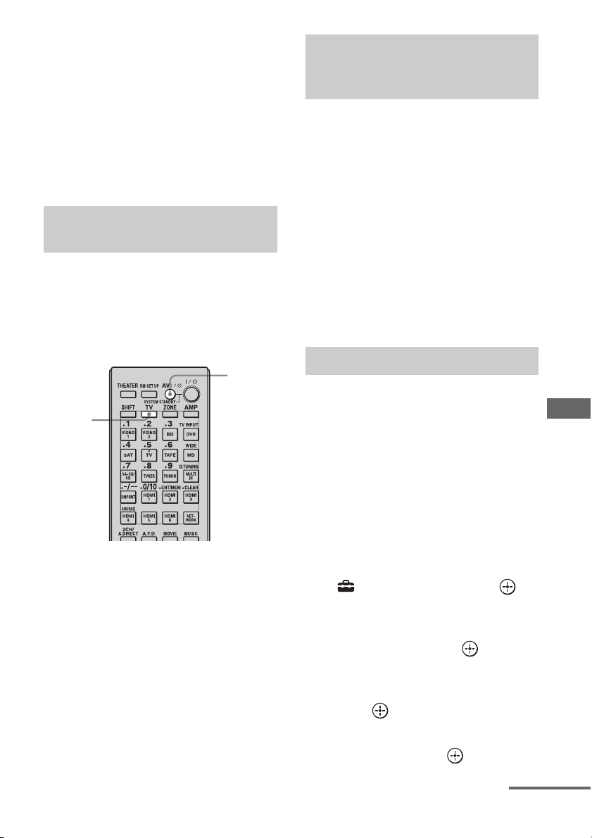
115
GB
Using Other Features
Notes
• When “Control for HDMI” is set to “ON,” the
“Audio Out” settings in the HDMI settings menu
will set automatically depending on the System
Audio Control settings.
• When you connect a TV that does not have System
Audio Control function, the System Audio Control
function does not work.
• If the TV is turned on before turning on the
receiver, the TV sound will not be output for a
moment.
When you turn the TV off by using the power
button on the TV’s remote, the receiver and
the connected components turn off
automatically.
You can also use the multifunction remote to
turn off the TV.
Press TV, then press AV ?/1.
The TV, receiver and connected components
are turned off.
Notes
• Set the TV power supply interlock function to on
before using the System Power Off function. For
details, refer to the operating instructions of the
TV.
• Depending on the status, the connected
components may not be turned off. For details,
refer to the operating instructions of the connected
components.
Press the THEATER button on the
remote of the receiver, TV, or the
Blu-ray Disc Player, while pointing
the remote toward the TV.
The sound field switches to HD-D.C.S.
To return to the previous sound field, press the
THEATER button again.
Note
The sound field may not switch depending on the
TV.
Tip
The sound field may be changed back to the
previous one when you change the TV’s input.
This function switches the sound field to HD-
D.C.S. automatically when 24p (24 frames per
second) signals are input from a playback
component, such as a Blu-ray Disc Player.
1 Press AMP.
The receiver can be operated using the
remote.
2 Press MENU.
The menu is displayed on the TV screen.
3 Press V/v repeatedly to select
“ Settings,” then press or
b.
4 Press V/v repeatedly to select
“HDMI,” then press or b.
5 Press V/v repeatedly to select
“24p Auto Sound Sync,” then
press or b.
6 Press V/v repeatedly to select
“ON,” then press or b.
Turning off the receiver with the
TV (System Power-Off)
TV
AV ?/1
Enjoying movies with the
optimum sound field (Theater
Mode Sync)
24p Auto Sound Sync
continued
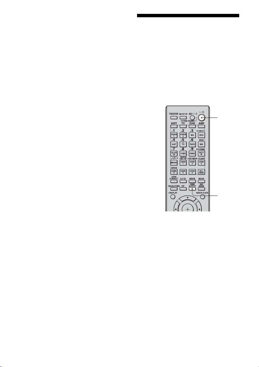
116
GB
7 Play back content containing
24p signals on a playback
component.
The sound field switches to HD-D.C.S.
automatically.
Notes
• This function does not work if a player is not
compatible with 24p Auto Sound Sync.
• When “Control for HDMI” is set to “ON,”
depending on the player, the sound field may not
switch to HD-D.C.S.
When “Control for HDMI” is set to “ON,” the
receiver detects the 24p signals via “BRAVIA”
Sync. Therefore, if a player that is not compatible
with “BRAVIA” Sync sends out 24p signals, the
receiver will not switch the sound field to HD-
D.C.S. In this case, set “Control for HDMI” to
“OFF.” When “Control for HDMI” is set to “OFF,”
the receiver detects the 24p signals by itself.
Switching the monitors
that output the HDMI
video signals
When you have two monitors connected to the
HDMI OUT A and HDMI OUT B jacks, you
can switch the output for these two monitors
using the HDMI OUTPUT button on the
multifunction remote. This operation cannot
be performed using the simple remote.
1 Turn on the receiver and the
two monitors.
2 Press HDMI OUTPUT.
Each time you press the button, the output
will be switched as follows:
HDMI A t HDMI B t HDMI A + B
t OFF t HDMI A…
You can also use the HDMI OUT button
on the receiver.
Notes
• If the compatible video format differs between the
monitors connected to the HDMI OUT A jack and
the HDMI OUT B jack of the receiver, “HDMI
A + B” may not work.
• Depending on the playback component you
connect, “HDMI A + B” may not work.
?/1
HDMI
OUTPUT
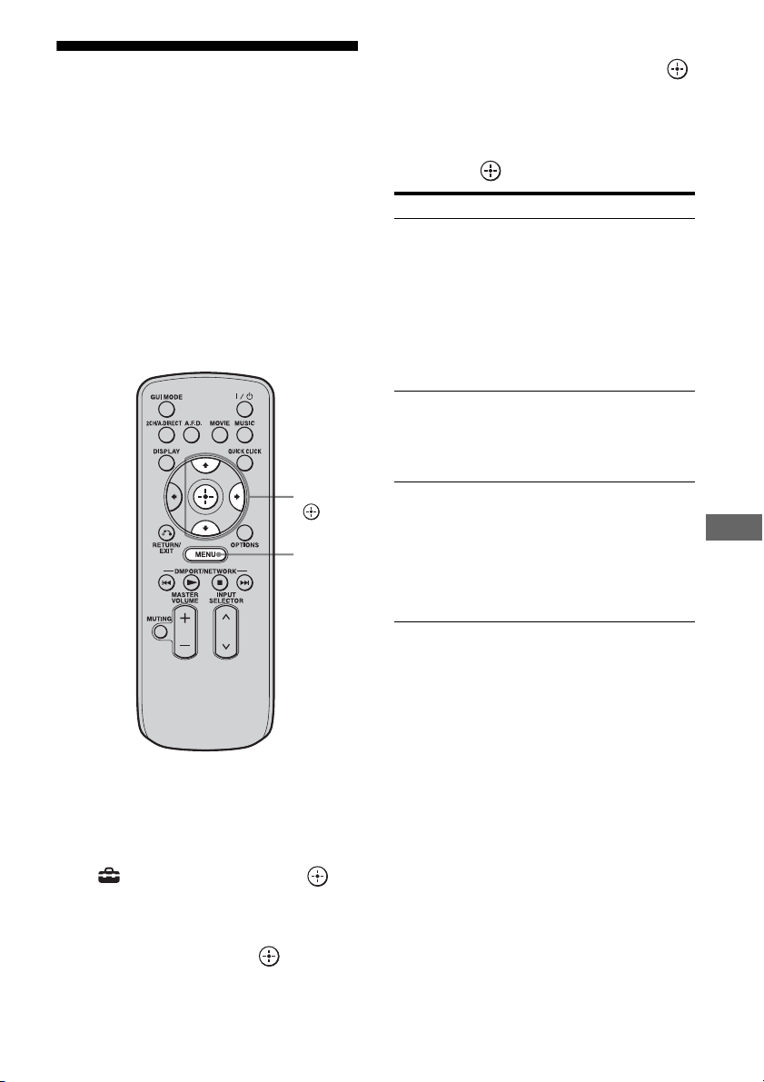
117
GB
Using Other Features
Outputting the HDMI
signals even when the
receiver is in standby
mode (Pass Through)
You can output the video and audio signals
from the HDMI IN jack to the TV connected to
the HDMI OUT jack even when the receiver is
in standby mode.
When you activate this function, make the
settings for “Pass Through” following the
steps below.
1 Press MENU.
The menu is displayed on the TV screen.
2 Press V/v repeatedly to select
“ Settings,” then press or
b.
3 Press V/v repeatedly to select
“HDMI,” then press or b.
4 Press V/v repeatedly to select
“Pass Through,” then press
or b.
5 Press V/v repeatedly to select
the parameter you want, then
press or b.
Notes
• This function does not work when you set “Control
for HDMI” to “OFF.”
• This function is available only when you select
“HDMI A” or “HDMI A + B” using the HDMI
OUTPUT button. When you select “HDMI B” or
“OFF,” this function does not work.
• When “AUTO” is selected, it may take a little more
time for the picture and sound to be output to the
TV than when “ON” is selected.
V/v/b,
MENU
Parameter Explanation
AUTO When the TV is turned on while
the receiver is in the standby
mode, the receiver outputs HDMI
signals from the receiver’s HDMI
OUT A jack. Sony recommends
this setting if you use a TV that is
compatible with “BRAVIA”
Sync. This setting saves power in
the standby mode compared with
the “ON” setting.
ON When the receiver is in the
standby mode, the receiver
continuously outputs HDMI
signals from the receiver’s HDMI
OUT A jack.
OFF The receiver does not output
HDMI signals when in the
standby mode. Turn on the
receiver to enjoy the connected
component’s source on the TV.
This setting saves power in the
standby mode, compared with the
“ON” setting.
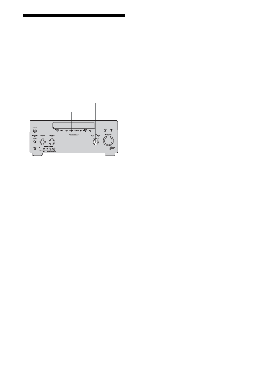
118
GB
Switching between
digital and analog audio
When you connect components to both digital
and analog audio input jacks on the receiver,
you can fix the audio input mode to either of
them, or switch from one to the other,
depending on the type of material you intend
to watch.
1 Select the input source using
INPUT SELECTOR on the
receiver.
2 Press INPUT MODE on the
receiver.
The selected audio input mode appears on
the TV screen.
•Auto
Gives priority to digital audio signals
when there are both digital and analog
connections.
If there are no digital audio signals,
analog audio signals are selected.
•Analog
Specifies the analog audio signals input
to the AUDIO IN (L/R) jacks.
Notes
• Some audio input modes may not be set up
depending on the input.
• When either the HDMI input, DIGITAL MEDIA
PORT adapter, Server, Rhapsody, SHOUTcast,
XM, or SIRIUS is selected, “------” appears on the
display, and you cannot select other modes. Select
an input other than the HDMI input, DIGITAL
MEDIA PORT adapter, Server, Rhapsody,
SHOUTcast, XM, or SIRIUS then set the audio
input mode.
• When “2ch Analog Direct” is being used, or the
multi-channel input is selected, audio input is set to
“Analog.” You cannot select other modes.
INPUT MODE
INPUT SELECTOR
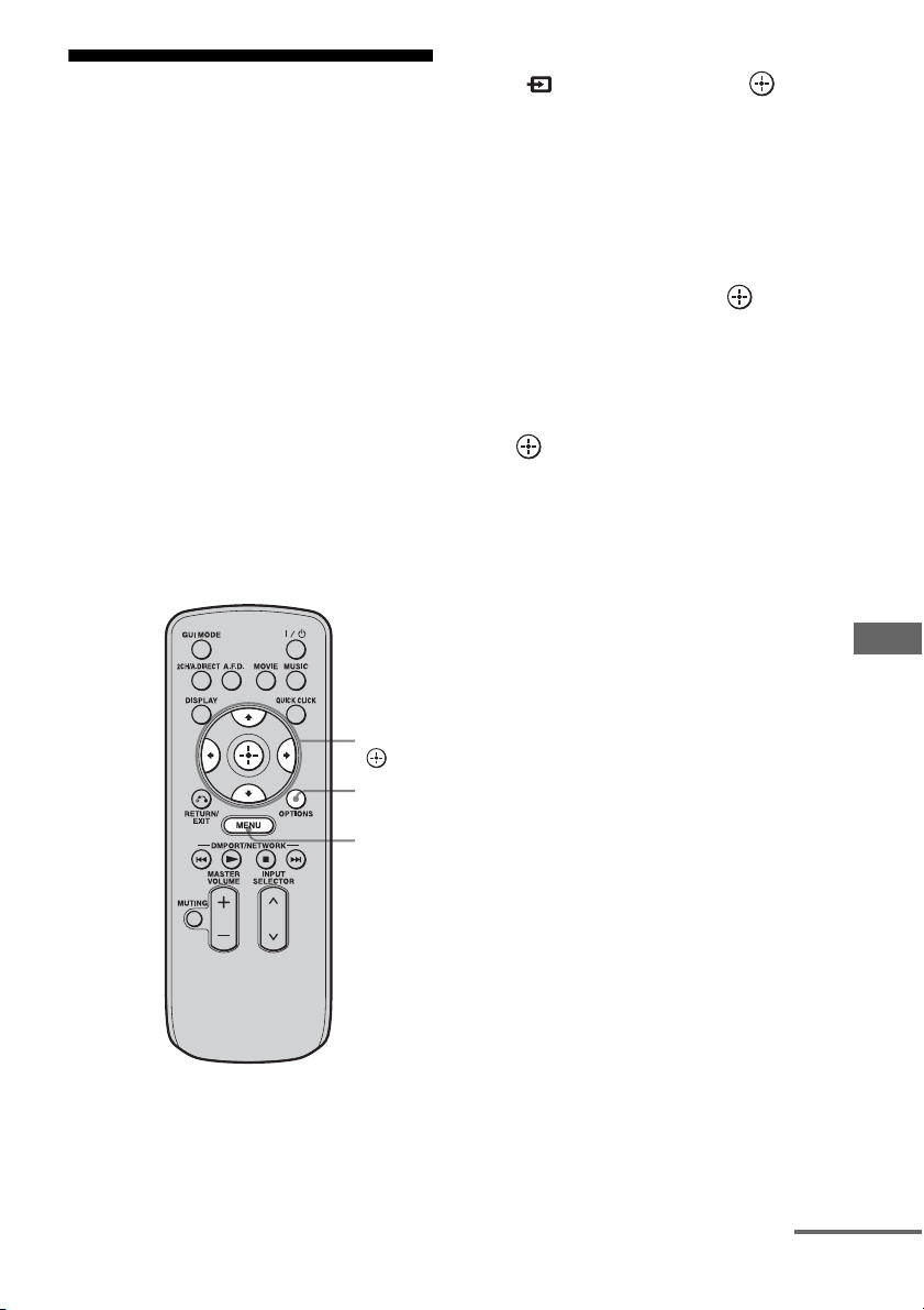
119
GB
Using Other Features
Enjoying the sound/
images from other inputs
(Input Assign)
You can reassign video and/or audio signals to
another input.
Example) Connect the OPTICAL OUT jack of
the DVD player to the OPTICAL VIDEO 1 IN
jack of this receiver when you want to input
the only digital optical audio signals from the
DVD player.
Connect the component video jack of the DVD
player to the COMPONENT VIDEO IN 1/
COMPONENT VIDEO IN 2, or
COMPONENT VIDEO IN 3 jack of this
receiver when you want to input the video
signals from the DVD player. Assign video
and/or audio signals to the DVD input jack
using “Input Assign” in the Input menu.
1 Press MENU.
The menu is displayed on the TV screen.
2 Press V/v repeatedly to select
“ Input,” then press or b.
3 Press V/v to select the input
name you want to assign.
4 Press OPTIONS.
The option menu appears.
5 Press V/v to select “Input
Assign,” then press .
6 Press V/v/B/b to select the
audio and/or video signals you
want to assign to the input
selected in step 3, then press
.
V/v/B/b,
MENU
OPTIONS
continued

120
GB
a)
Initial setting
b)
When you assign a component video input to the HDMI input via the Input Assign menu, component video
signals are not converted to HDMI video signals and are not output from the HDMI OUT jacks. Component
video signals are output from the COMPONENT VIDEO MONITOR OUT jack. In this case, the resolution
of the GUI output is set to “480p” for both component video input and HDMI video input.
Notes
• You cannot assign optical signals from an input
source to the optical input jacks on the receiver, and
you cannot assign coaxial signals from the input
source to the coaxial input jacks on the receiver.
• When you assign the digital audio input, the
INPUT MODE setting may change automatically.
• You cannot reassign more than one HDMI input to
the same input.
• You cannot reassign more than one digital audio
input to the same input.
• You cannot reassign more than one component
video input to the same input.
• When you assign a component video input to the
HDMI input, set “Control for HDMI” to “OFF.”
Input name
VIDEO1 VIDEO2 BD DVD SAT TAPE MD SA-CD/
CD
MULTI
IN
HDMI1 HDMI2 HDMI3 HDMI4 HDMI5 HDMI6
Assignable
video input
jacks
Video1
Composite
a
a)
––––––– –––––––
Video2
Composite
– a
a)
–––––––––––––
BD
Composite
––a ––––––––––––
DVD
Composite
–––a –––––––––––
SAT
Composite
––––a ––– –––––––
Component1
aaa
a)
aaaa a a a
b)
a
b)
a
b)
a
b)
a
b)
a
b)
Component2
aaaa
a)
aaa a a a
b)
a
b)
a
b)
a
b)
a
b)
a
b)
Component3
aaaaa
a)
aa a a a
b)
a
b)
a
b)
a
b)
a
b)
a
b)
HDMI1 aaaaaaaaaa
a)
–––––
HDMI2 aaaaaaaaa– a
a)
––––
HDMI3 aaaaaaaaa––a
a)
–––
HDMI4 aaaaaaaaa–––a
a)
––
HDMI5 aaaaaaaaa––––a
a)
–
HDMI6 aaaaaaaaa–––––a
a)
Assignable
audio input
jacks
Video1
OPT
a
a)
– aa –––a –––––––
Video2
OPT
– a
a)
aa –––a –––––––
SAT OPT – – aaa
a)
–– a –––––––
Tape OPT – – aa – a
a)
– a –––––––
MD OPT – – aa ––a
a)
a –––––––
BD COAX aaa
a)
– aaa ––––––––
DVD
COAX
aa– a
a)
aaa ––––––––
SA-CD/CD
COAX
aa––aaaa
a)
–––––––
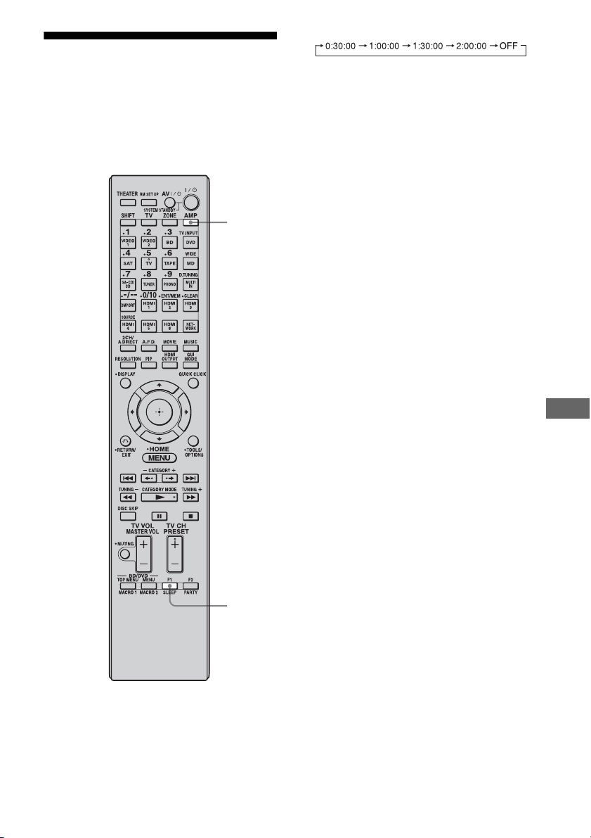
121
GB
Using Other Features
Using the sleep timer
You can set the receiver to turn off
automatically at a specified time.
Use the multifunction remote for this
operation. This operation cannot be performed
using the simple remote.
1 Press AMP.
2 Press SLEEP repeatedly.
Each time you press SLEEP, the display
changes cyclically as follows:
When sleep timer is being used, “SLEEP”
lights up in the display window of the
receiver.
Tip
To check the remaining time before the receiver
turns off, press SLEEP. The remaining time appears
on the display. If you press SLEEP again, the sleep
timer will be changed.
SLEEP
AMP
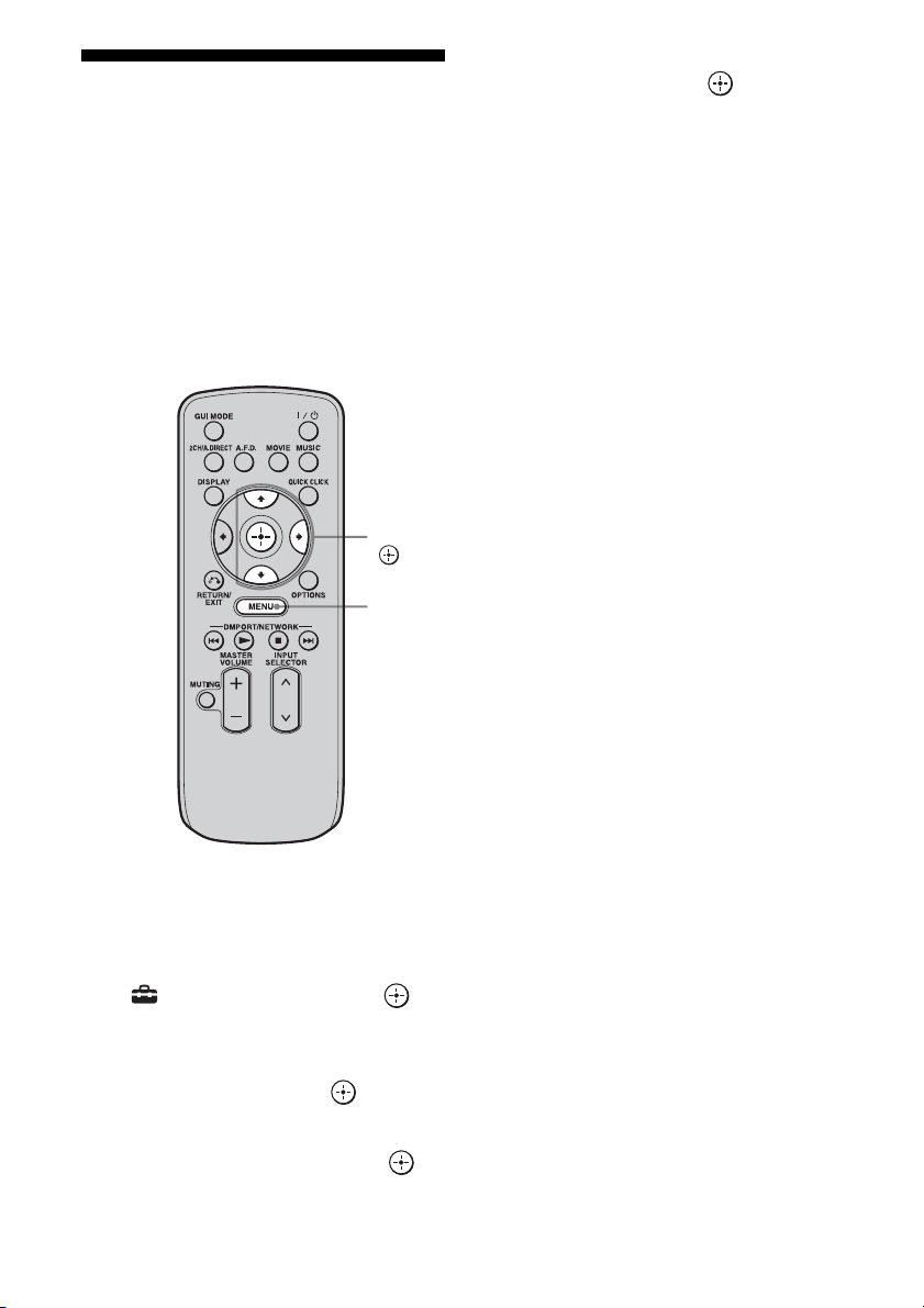
122
GB
Enjoying the surround
effect at low volume
levels
This function allows you to retain a theater like
environment at low volume levels. This
function can be used with other sound fields.
When watching a movie late at night, you will
be able to hear the dialog clearly even at a low
volume level.
1 Press MENU.
The menu is displayed on the TV screen.
2 Press V/v repeatedly to select
“ Settings,” then press or
b.
3 Press V/v repeatedly to select
“Audio,” then press or b.
4 Press V/v repeatedly to select
“Night Mode,” then press .
5 Press V/v repeatedly to select
“On,” then press .
Notes
• This function does not work when the multi-
channel input is selected.
• This function does not work when “2ch Analog
Direct” is being used.
• This function does not work when Dolby TrueHD
signals with a sampling frequency of 176.4 kHz
and higher are being received.
• If the Night Mode function is turned on while the
receiver is receiving signals with a sampling
frequency of 176.4 kHz and higher, the signals will
always be played back at either 44.1 kHz or
48 kHz.
Tip
While this function is on, the Bass, Treble increase,
and “D. Range Comp” is automatically set to
“MAX.”
V/v/b,
MENU

123
GB
Using Other Features
Recording using the
receiver
You can record from a video/audio component
using the receiver. Refer to the operating
instructions supplied with your recording
component.
You can record onto a MiniDisc or audio tape
using the receiver. Refer to the operating
instructions supplied with your MD deck or
tape deck.
1 Press MENU.
2 Press V/v repeatedly to select
“ Input,” then press or b.
3 Press V/v to select the
playback component, then
press .
4 Prepare the playback
component for playing.
For example, insert a CD into the CD
player.
5 Prepare the recording
component.
Insert a blank MD or tape into the
recording deck and adjust the recording
level.
6 Start recording on the
recording deck, then start
playback on the playback
component.
Notes
• Sound adjustments do not affect the signal output
from the MD OUT jacks.
• The audio input signals from the MULTI
CHANNEL INPUT jacks are not output.
To record digital sound
Connect a component for playback to the
digital audio input (OPTICAL IN) jack, and
connect the recording component to the
OPTICAL MD OUT jack.
1 Press MENU.
2 Press V/v repeatedly to select
“ Input,” then press or b.
3 Press V/v to select the
playback component, then
press .
4 Prepare the component for
playing.
For example, insert the video tape you
want to copy into the VCR.
Recording onto a MiniDisc or
audio tape
V/v/b,
MENU
Recording onto recording media
continued
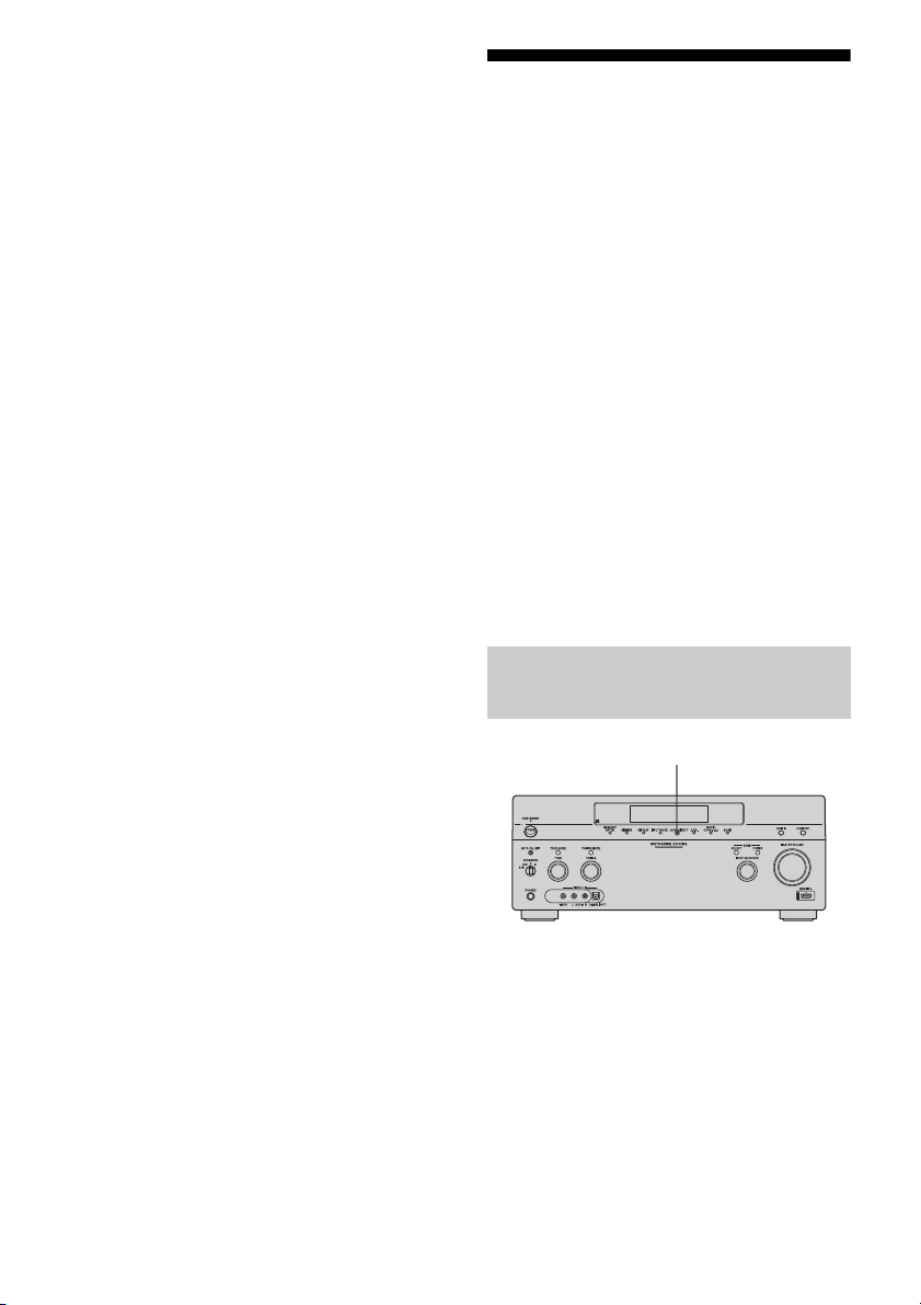
124
GB
5 Prepare the recording
component.
Insert a blank video tape, etc., into the
recording component (VIDEO 1) for
recording.
6 Start recording on the
recording component, then
start playback on the playback
component.
Notes
• Some sources contain copy guards to prevent
recording. In this case, you may not be able to
record from the sources.
• The audio input signals from the MULTI
CHANNEL INPUT jacks are not output.
• Only analog input signals are output from the
analog output jack (for recording).
• Only digital input signals are output from the
digital output jack (for recording).
• HDMI sound cannot be recorded.
Switching the command
mode of the receiver and
the remote
You can switch the command mode
(COMMAND MODE AV 1 or COMMAND
MODE AV 2) of the receiver and the remote.
Switch the command mode from the initial
setting to the appropriate setting, if other Sony
component is operated accidentally by the
same remote, when you are operating the
receiver using the remote supplied with the
receiver.
The command modes of both the receiver and
the remote are those of the initial setting
(COMMAND MODE AV 2).
The receiver and the remote, on the contrary,
should use the same command mode. If the
command modes of the receiver and the
remote are different, you cannot use the
remote to operate the receiver.
Turn on the receiver while pressing
2CH/A.DIRECT.
When the command mode is set to “AV2,”
“COMMAND MODE [AV2]” appears on the
display.
When the command mode is set to “AV1,”
“COMMAND MODE [AV1]” appears on the
display.
Switching the command mode of
the receiver
2CH/A.DIRECT
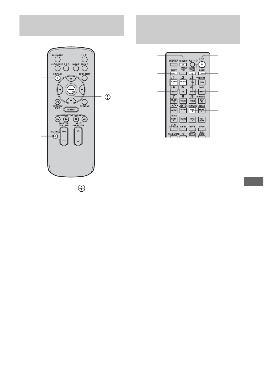
125
GB
Using Other Features
Press MUTING and at the same
time while pressing DISPLAY.
1 Press ?/1 while pressing RM
SET UP.
The AMP and ZONE buttons flash.
2 Press AMP.
The ZONE button goes off, the AMP
button keeps flashing and the SHIFT
button lights up.
3 Press the numeric button 1 or 2
while the AMP button is
flashing.
When you press 1, the command mode is
set to AV SYSTEM 1. When you press 2,
the command mode is set to AV SYSTEM
2.
The AMP button lights up.
4 Press ENT/MEM.
The AMP button flashes twice, then the
command mode setting process is
completed.
Switching the command mode of
the simple remote commander
DISPLAY
MUTING
Switching the command mode of
the multifunction remote
commander
ZONE
?/1
AMP
ENT/
MEM
1, 2
RM SET
UP
SHIFT
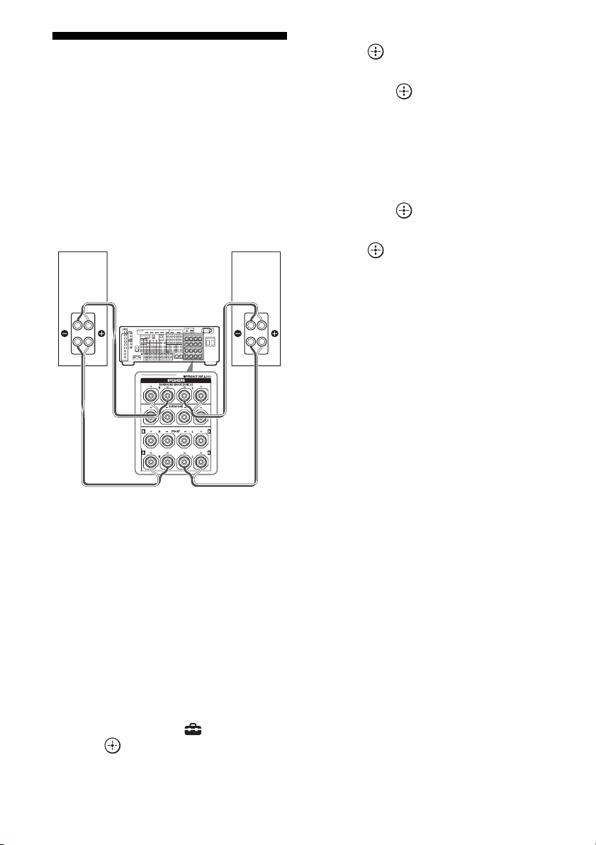
126
GB
Using a bi-amplifier
connection
If you are not using surround back speakers,
you can use the SURROUND BACK
SPEAKERS terminals for the front speakers
for use with a bi-amplifier connection.
To connect speakers
Connect the jacks on the Lo (or Hi) side of the
front speakers to the FRONT SPEAKERS A
terminals, and connect the jacks on the Hi (or
Lo) side of the front speakers to the
SURROUND BACK SPEAKERS terminals.
Make sure that metal fittings of Hi/Lo attached
to the speakers have been removed from the
speakers. Not doing so may cause a
malfunction of the receiver.
To set up speakers
1
Press MENU.
The menu is displayed on the TV screen.
2 Press V/v to select “ Settings,” then
press or b.
3 Press V/v to select “Speaker,” then
press or b.
4 Press V/v to select “Speaker Pattern,”
then press .
5 Press V/v to select the appropriate
speaker pattern so that there are no
surround back speakers.
6 Press RETURN/EXIT O.
7 Press V/v to select “Sur Back Assign,”
then press .
8 Press V/v to select “BI-AMP,” then
press .
The same signals output from the FRONT
SPEAKERS A terminals can be output
from the SURROUND BACK SPEAKERS
terminals.
Notes
• You cannot use the FRONT SPEAKERS B
terminals for a bi-amplifier connection.
• When you use the auto calibration function, make
the bi-amplifier settings before you perform auto
calibration.
• If you make the bi-amplifier settings, the speaker
level, balance, and equalizer settings of the
surround back speakers become invalid, and those
of the front speakers are used.
• Signals output from the PRE OUT jacks are used
with the same settings as those of the SPEAKERS
terminals.
• If the Speaker Pattern is set to the setting that there
are surround back speakers, you cannot make the
bi-amplifier settings.
Front speaker
(R)
Front speaker
(L)
Hi
Lo
Hi
Lo
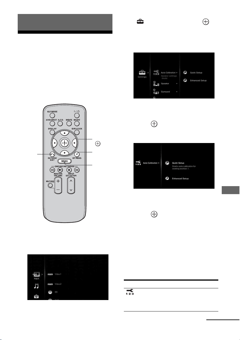
127
GB
Adjusting Settings
1
Using the setting menu
You can adjust the various settings for
speakers, surround effects, multi zone, etc.
using the setting menu.
To display the menu of the receiver on the TV
screen, make sure that the receiver is in “GUI
MODE” by following the step in “To turn
“GUI MODE” on and off” (page 60).
1 Press MENU.
The menu is displayed on the TV screen.
2 Press V/v repeatedly to select
“ Settings,” then press or
b to enter the menu mode.
The setting menu list appears on the TV
screen.
3 Press V/v repeatedly to select
the menu item you want, then
press to enter.
Example: When you select “Auto Calibration”
4 Press V/v repeatedly to select
the parameter you want, then
press to enter.
To return to the previous screen
Press RETURN/EXIT O.
To exit the menu
Press MENU.
Setting menu list
Adjusting Settings
V/v/B/b,
MENU
RETURN/
EXIT O
OPTIONS
Menu icon Description
Auto
Calibration
Sets the speaker level or
distance and makes the
measurement automatically
(page 128).
continued
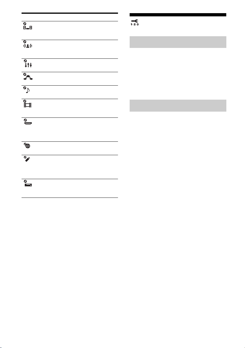
128
GB
Auto Calibration
Performs Auto Calibration. For details, see “8:
Calibrating the appropriate speaker settings
automatically (Auto Calibration)” (page 50).
Note
The measurement results will be overwritten and
saved on Position 1 in the Enhanced Setup menu.
You can register three patterns for “Seating
Position” depending on the seating positions,
listening environment, and measurement
conditions.
You can also select a calibration type to
compensate the each speaker.
To register more than one set of
settings for the listening
environment
You can select the seating position you want
and register the measurement results of the
auto calibration for that seating position.
1 Press V/v repeatedly on the Enhanced
Setup screen to select the “Seating
Position” for which you want to register
the measurement results.
• Pos. (Position) 1
• Pos. (Position) 2
• Pos. (Position) 3
2 Press b to perform auto calibration.
To set a compensation type for
the speakers
You can select the compensation type to be
used for the speakers for each Seating
Position.
Speaker Sets the speaker position and
impedance manually
(page 130).
Surround Adjusts the sound field
(surround effect) you
selected (page 134).
EQ Adjusts the equalizer (bass/
treble sound) (page 136).
Multi Zone Makes the settings for Multi
Zone (page 136).
Audio Sets various sound items
(page 138).
Video Adjusts the resolution of
analog video signals
(page 140).
HDMI Makes settings for sound/
images from components
connected to the HDMI jacks
(page 142).
Network Makes the settings for the
network (page 144).
Quick Click Controls components
connected to the receiver
using the on-screen remote
(page 145).
System Sets the screen saver or
language of the menu guide
display (page 146).
Menu icon Description
Quick Setup
Enhanced Setup

129
GB
Adjusting Settings
1 Press V/v repeatedly to select the
“Seating Position” for which you want to
set the speaker compensation type,
then press .
2 Press V/v repeatedly to select
“Calibration Type” you want, then press
.
• Full Flat
Makes the measurement of frequency
from each speaker flat.
•Engineer
Sets the frequency to match that of the
Sony listening room standard.
• Front Reference
Adjusts the characteristics of all the
speakers to match the characteristics of
the front speakers.
•OFF
Sets the auto calibration EQ to off.
Note
You cannot set “Calibration Type” for “Seating
Position” for which the measurement results have
not been registered.
To confirm the equalizer setting
for the Seating Position
1
Press V/v repeatedly to select the
“Seating Position” for which you want to
confirm the equalizer setting.
2 Press OPTIONS.
The option menu appears.
3 Press V/v repeatedly to select “EQ
Curve,” then press .
4 Press B/b repeatedly to select the
speaker on the screen for which you
want to confirm the equalizer setting.
• FRONT
• CENTER
• SURROUND
• SURROUND BACK
To name the Seating Position
1
Press V/v repeatedly to select the
“Seating Position” for which you want to
name.
2 Press OPTIONS.
The option menu appears.
3 Press V/v repeatedly to select “Name
Input,” then press .
The soft keyboard appears on the screen.
4 Press V/v/B/b and to select a
character one by one.
5 Press V/v/B/b to select “Finish,” then
press .
130
GB
Speaker settings
You can adjust each speaker manually. You
can also adjust the speaker levels after the auto
calibration is completed.
Note
The Speaker settings are only for the current
“Seating Position.”
You can set the speaker impedance. For
details, see “7: Setting the speakers”
(page 48).
x 4 Ω
x 8 Ω
Select “Speaker Pattern” according to the
speaker system which you are using. You do
not need to select the speaker pattern after auto
calibration.
To select the speaker pattern
1
Press V/v repeatedly to select
“Speaker Pattern,” then press .
The Speaker Pattern screen appears.
2 Press V/v to select the speaker pattern
you want, then press .
3 Press RETURN/EXIT O.
You can set the analog downmix settings on or
off.
x OFF
If there is a center speaker connected, this
setting is set to “OFF” automatically.
x ON
We recommend you set “Center Mix” to “ON”
to enjoy digital audio with high quality sound
when you do not have a center speaker
connected. Analog downmix works when you
set “Center Mix” to “ON.” This setting is also
effective to input signals from the MULTI
CHANNEL INPUT jacks.
You can make settings for the surround back
speaker(s).
x OFF
If you have not connected surround back
speakers, select “OFF.”
x BI-AMP
If you connect front speakers in a bi-amplifier
configuration, select “BI-AMP” (page 126).
x ZONE2
If you are using the surround back speakers in
zone 2, select “ZONE2.” When you select
“ZONE2,” the input to the SUR BACK jacks
of the MULTI CHANNEL INPUT is invalid
(page 108).
Note
Set “Sur Back Assign” to “OFF,” then connect the
surround back speakers to this receiver when you
want to change the connection from a bi-amplifier
connection or a zone 2 connection to a surround
back speakers connection. Re-set up the speakers
after you connect the surround back speakers. See
“Auto Calibration” (page 50) or “Manual Setup”
(page 131).
Impedance
Speaker Pattern
Center Mix
Sur Back Assign
131
GB
Adjusting Settings
You can adjust each speaker manually on the
Manual Setup screen. You can also adjust the
speaker levels after the auto calibration is
completed.
To adjust the speaker level
You can adjust each speaker’s level (center,
surround left/right, surround back left/right,
subwoofer).
1 Press V/v/B/b repeatedly to select the
speaker on the screen for which you
want to adjust the level, then press .
2 Press B/b repeatedly to select “Level:,”
then press .
3 Press V/v to set the level of the
selected speaker, then press .
You can adjust the level from –20 dB to
+10dB in 0.5dB steps.
For the front left/right speakers, you can
adjust the balance on either side. You can
adjust the front left level from FL–10.0 dB
to FL+10.0 dB in 0.5 dB steps. You can
also adjust the front right level from
FR–10.0 dB to FR+10.0 dB in 0.5 dB
steps.
Note
When one of the sound fields for music is selected,
no sound is output from the subwoofer if all the
speakers are set to “LARGE.” However, the sound
will be output from the subwoofer if the digital input
signal contains L.F.E. signals, or if the front or
surround speakers are set to “SMALL,” the sound
field for movie is selected, or “Portable Audio” is
selected.
To adjust the distance from the
seating position to each
speaker
You can adjust the distance from the seating
position to each speaker (front left/right,
center, surround left/right, surround back left/
right, subwoofer.)
1 Press V/v/B/b repeatedly to select the
speaker on the screen for which you
want to adjust the distance from the
seating position, then press .
2 Press B/b repeatedly to select a
“Distance:,” then press .
3 Press V/v to set the distance of the
selected speaker, then press .
You can adjust the distance from 1.0 meter
to 10.0 meters (3 feet 3 inches to 32 feet
9 inches) in 1 cm (1 inch) steps.
To adjust the size of each
speaker
You can adjust each speaker’s (front left/right,
center, surround left/right, surround back left/
right) size.
1 Press V/v/B/b repeatedly to select the
speaker on the screen for which you
want to adjust the size, then press .
2 Press B/b repeatedly to select a “Size:,”
then press .
3 Press V/v to set the size of the selected
speaker, then press .
•LARGE
If you connect large speakers that will
effectively reproduce bass frequencies,
select “LARGE.” Normally, select
“LARGE.”
•SMALL
If the sound is distorted, or you feel a lack
of surround effects when using multi-
channel surround sound, select
“SMALL” to activate the bass redirection
circuitry and output the bass frequencies
of each channel from the subwoofer or
other “LARGE” speakers.
Manual Setup
continued

132
GB
Tips
• The “LARGE” and “SMALL” settings for each
speaker determine whether the internal sound
processor will cut the bass signal from that
channel.
When the bass is cut from a channel, the bass
redirection circuitry sends the corresponding bass
frequencies to the subwoofer or other “LARGE”
speakers.
However, since bass sound has a certain amount of
directionality, it is best not to cut it, if possible.
Therefore, even when using small speakers, you
can set them to “LARGE” if you want to output the
bass frequencies from that speaker. On the other
hand, if you are using a large speaker, but prefer not
to have bass frequencies output from that speaker,
set it to “SMALL.”
If the overall sound level is lower than you prefer,
set all speakers to “LARGE.” If there is not enough
bass, you can use the equalizer to boost the bass
levels.
• The surround back speakers will be set to the same
setting as that of the surround speakers.
• When the front speakers are set to “SMALL,” the
center, surround, and surround back speakers are
also automatically set to “SMALL.”
• If you do not use the subwoofer, the front speakers
are automatically set to “LARGE.”
Lets you set the bass crossover frequency of
speakers that has been set to “SMALL” in the
Speaker menu. Measured speaker crossover
frequency is set for each speaker after the auto
calibration.
1 Press B/b to select the speaker
on the screen you want to
adjust.
2 Press V/v to adjust the value,
then press b or RETURN/EXIT
O.
You can select the test tone type on the Test
Tone screen.
Tips
• To adjust the level of all speakers at the same time,
press MASTER VOLUME +/–.
• The adjusted value is shown on the display during
adjustment.
To output a test tone from each
speaker
You can output a test tone from the speakers in
sequence.
1 Press B/b to select “Test Tone,” then
press .
The Test Tone screen appears.
2 Press V/v to adjust the parameter, then
press .
•OFF
•AUTO
The test tone is output from each speaker
in sequence.
• L, C, R, SR, SBR, SBL, SL, SW
You can select which speakers will output
the test tone.
3 Press V/v to adjust “Level:,” then press
.
To output a test tone from
adjacent speakers
You can output a test tone from adjacent
speakers so that you can adjust the balance
between the speakers.
1 Press B/b to select “Phase Noise,” then
press .
The Phase Noise screen appears.
2 Press V/v to adjust the parameter, then
press .
•OFF
• L/R, L/C, C/R, R/SL, R/SR, SR/SL, SR/
SBR, SBR/SBL, SR/SB, SBL/SL, SB/
SL, SL/L, L/SR
Lets you output the test tone sequentially
Crossover Freq (Speaker
crossover frequency)
Test Tone

133
GB
Adjusting Settings
from adjacent speakers.
Some items may not be displayed,
depending on the setting of the speaker
pattern.
3 Press V/v to adjust “Level:,” then press
.
To output the source sound
from adjacent speakers
You can output the source sound from adjacent
speakers so that you can adjust the balance
between the speakers.
1 Press B/b to select “Phase Audio,” then
press .
The Phase Audio screen appears.
2 Press V/v to adjust the parameter, then
press .
•OFF
• L/R, L/C, C/R, R/SL, R/SR, SR/SL, SR/
SBR, SBR/SBL, SR/SB, SBL/SL, SB/
SL, SL/L, L/SR
Lets you output front 2 channel source
sound (instead of the test tone)
sequentially from adjacent speakers.
Some items may not be displayed,
depending on the setting of the speaker
pattern.
3 Press V/v to adjust “Level:,” then press
.
When a test tone is not output
from the speakers
• The speaker cords may not be connected
securely. Check to see if they are connected
securely and cannot be disconnected by
pulling on them slightly.
• The speaker cords may have the short-circuit
problem.
When a test tone is output from
a different speaker than the
speaker displayed on the
screen
The speaker pattern to the connected speaker
is not set up correctly. Make sure the speaker
connection and the speaker pattern match.
Lets you compress the dynamic range of the
soundtrack. This may be useful when you want
to watch movies at low volumes late at night.
Dynamic range compression is possible with
Dolby Digital sources only.
x OFF
The dynamic range is not compressed.
x AUTO
The dynamic range is compressed
automatically.
x STD
The dynamic range is compressed as intended
by the recording engineer.
x MAX
The dynamic range is compressed
dramatically.
Tips
• Dynamic range compressor lets you compress the
dynamic range of the soundtrack based on the
dynamic range information included in the Dolby
Digital signal.
• “STD” is the standard setting, but it only enacts
light compression. Therefore, we recommend
using the “MAX” setting. This greatly compresses
the dynamic range and lets you view movies late at
night at low volumes. Unlike analog limiters, the
levels are predetermined and provide a very natural
compression.
D. Range Comp (Dynamic range
compressor)

134
GB
Lets you select the unit of measure for setting
distances.
x meter
The distance is displayed in meters.
x feet
The distance is displayed in feet.
Surround settings
You can adjust the sound effect on the Sound
Field Setup screen.
Note
The setup items you can adjust on each menu vary
depending on the sound field.
You can select the surround sound field and
adjust the effect level on the Sound Field Setup
screen.
For details on the sound field, see “Enjoying
Surround Sound” (page 82).
To select the surround sound
field
1
Press V/v repeatedly to select “Sound
Field Setup,” then press .
2 Press V/v repeatedly to select the
surround sound you want.
3 Press RETURN/EXIT O.
To select the Effect Type for HD-
D.C.S.
1
Press V/v repeatedly to select “Sound
Field Setup,” then press .
2 Press V/v repeatedly to select “HD-
D.C.S.,” then press b.
3 Press V/v to select the Effect Type you
want, then press B.
HD-D.C.S. has three different types:
Theater, Dynamic, and Studio. Each type
has different reflection and reverberation
sound mixture levels and is optimized to
match a listener’s room uniqueness, taste
and mood.
Distance Unit (Distance unit)
Sound Field Setup

135
GB
Adjusting Settings
• Theater
Theater type (default setting) mixes
reflection and reverberation sound
creating the characteristics of a mastering
studio. Additionally, this type mixes in
frequency characteristics that are often
found in professional studios and movie
theaters. It is ideal for watching movies in
a listening room that has less
reverberation.
•Dynamic
Want to enjoy the sound effects to the full
extent, just like at the movie theaters?
Dynamic type emphasizes on the
reflection sound. Without HD-D.C.S.,
many rooms are often somewhat
reverberant but lack a spacious feeling.
This type acoustically opens up those
types of rooms and provides a spacious
and dynamism feeling equivalent to a
mastering studio.
•Studio
In Studio type, effects are kept to a
minimum, while still providing a great
theater experience. This type provides the
accuracy of the original recording.
4 Press RETURN/EXIT O.
You can select the decoding mode for the
sound field.
For details on the decoding modes available,
see “Setting a multi-channel surround sound
effect” (page 84).
x Pro Logic II
Performs Dolby Pro Logic II decoding. A
source recorded in 2 channel format is
decoded into 5.1 channels.
x Pro Logic IIx
Performs Dolby Pro Logic IIx decoding. A
source recorded in 2 channel or 5.1 channel
format is decoded into 7.1 channels.
x Neo:6 Cinema
Performs DTS Neo:6 Cinema mode decoding.
A source recorded in 2 channel format is
decoded into 7 channels.
x Neo:6 Music
Performs DTS Neo:6 Music mode decoding.
A source recorded in 2 channel format is
decoded into 7 channels. This setting is ideal
for normal stereo sources such as CDs.
x Neural-THX
Next generation of Neural-THX
®
Surround. In
addition to stereo enhancement processing and
pure discrete 5.1 surround sound, now capable
of full 360° 7.1 surround sound playback from
Neural-THX
®
surround encoded content.
Note
You can select “Pro Logic II” when there is no
surround back speaker on the Speaker Pattern menu,
or you can select “Pro Logic IIx” when there is a
surround back speaker. You cannot select both
settings at the same time.
Enhanced Sur Mode
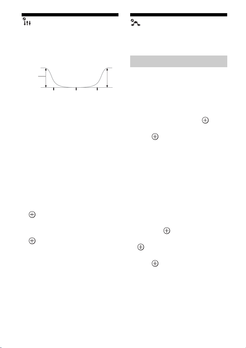
136
GB
EQ settings
You can use following parameters to adjust the
tonal quality (bass/treble level) of front, center
and surround/surround back speakers.
Notes
• This function does not work in the following cases.
– The multi-channel input is selected.
– “2ch Analog Direct” is being used.
– Dolby TrueHD signals with a sampling
frequency of 176.4 kHz and higher are being
received.
• If the equalizer is adjusted while the receiver is
receiving signals with a sampling frequency of
176.4 kHz and higher, the signals will always be
played back at either 44.1 kHz or 48 kHz.
To adjust the equalizer on the
EQ screen
1
Press B/b to select the speaker on the
screen you want to adjust, then press
.
2 Press B/b to select “Bass” or “Treble.”
3 Press V/v to adjust the gain, then press
.
Multi Zone settings
You can make settings for the main zone, zone
2 or zone 3.
To turn the power on or off for
zone 2/zone 3
You can turn zone 2 or zone 3 operation on or
off. “Main” (this receiver) is always selected.
You cannot turn it off.
1 Press V/v to select the zone you want
to turn on or off, then press .
2 Press V/v to select “ON” or “OFF,” then
press .
x ON
x OFF
To select the output source for
each zone
You can select the source that is output to the
zone. Audio and video signals are output to
zone 2, while only audio signals are output to
zone 3.
1 Press V/v to select the zone to which
you want to output audio/video signals,
then press .
2 Press B/b to select “Input,” then press
.
3 Press V/v to select the input, then
press .
Level
(dB)
Bass Treble
Frequency
(Hz)
Multi Zone Setup

137
GB
Adjusting Settings
To adjust the volume for zone 2
You can adjust the volume in the main zone.
If “Sur Back Assign” is set to “ZONE2” in the
Speaker settings menu, you can also adjust the
volume of zone 2.
1 Press V/v to select the zone for which
you want to adjust the volume, then
press .
2 Press B/b to select “Volume,” then
press .
3 Press V/v to adjust the volume, then
press .
To select the criteria for output
of signals to control each zone
You can turn the receiver on or off in another
zone, or select various options for use of the
12V Trigger function.
1 Press V/v to select the zone you want,
then press .
2 Press B/b to select “12V Trigger.”
3 Press V/v to select the parameter, then
press .
x OFF
Lets you turn off output of 12V triggers even
when the main receiver is turned on.
x CTRL
Lets you turn the output of 12V triggers on or
off manually using the CIS command of the
external control device.
x ZONE
Lets you turn the output of 12V triggers on or
off based on whether the selected zone is
turned on or off.
x INPUT (for “Main” only)
Lets you turn on the output of 12V triggers
when the preset input is selected.
When you select “Input,” the setting display
which sets each input trigger to on/off appears.
Press V/v to select the input, then press to
check the box.
x HDMI A (for “Main” only)
Lets you turn the output of 12V triggers on or
off based on the output setting of the HDMI
OUT A jack.
x HDMI B (for “Main” only)
Lets you turn the output of 12V triggers on or
off based on the output setting of the HDMI
OUT B jack.
x MAIN (for “Zone2” and “Zone3”
only)
Lets you link operation of trigger in zone 2 or
zone 3 to the main receiver.
Tips
• Even when this receiver is standby mode (press
?/1 on the remote to turned off this receiver), the
receiver in zone 2 or zone 3 remains turned on. To
turn off all receivers, press ?/1 and AV ?/1 on the
multifunction remote at the same time (SYSTEM
STANDBY).
• Only signals from components connected to the
analog input jacks are output through the ZONE 2
OUT/ZONE 3 OUT jacks. No signals are output
from components connected to only the digital
input jacks.
• When SOURCE is selected, the signals input to the
MULTI CHANNEL INPUT jacks are not output
from the ZONE 2 OUT or ZONE 3 OUT jacks
even when the multi-channel input is selected. The
analog audio signals of the current function are
output.
• When “Tuner” is selected; the same type of radio
station (FM/AM) selected in the main zone is set in
zone 2 and zone 3. However, you can select the
input other than “Tuner” in zone 2 and zone 3.
• When the receiver in the main zone is turned off, or
an input source other than “Tuner” is selected, you
can select a radio station from AM or FM in zone 2
or zone 3.
When two of the receivers in the main zone, zone 2
or zone 3 are turned off and an input source other
than “Tuner” is selected, you can select a broadcast
from FM/AM in one zone in which the receiver is
turned on.

138
GB
Lets you select the zone which plays back the
same music as the main zone when you press
the PARTY button to start the party mode.
x ZONE2+ZONE3
x ZONE2
x ZONE3
Audio settings
You can make settings for the audio to suit
your preference.
When you set this setting to “AUTO,” the
receiver plays back the sound recorded using
lossy compression with high quality sound. If
the CD sound is recorded using Linear PCM,
the CD sound quality level will be increased
further.
x OFF
x AUTO
Note
D.L.L. is available for LPCM 44.1 kHz, Dolby
Digital, DTS, or analog signals.
Lets you delay the output of audio to minimize
the time gap between audio output and visual
display.
x HDMI AUTO
The time gap between audio output and visual
display for the monitor connected via an
HDMI connection will be adjusted
automatically based on the information for the
TV. This feature is available only when the
monitor supports the A/V Sync function.
x 0 ms – 300 ms
You can adjust the delay from 0 ms to 300 ms
in 10 ms steps.
Notes
• This function is useful when you use a large LCD
or plasma monitor or a projector.
• This function does not work in the following cases.
– The multi-channel input is selected.
– “2ch Analog Direct” is being used.
Party Setup
Digital Legato Linear (D.L.L.)
A/V Sync (Synchronizes audio
and video output)

139
GB
Adjusting Settings
Lets you select the language you want when
you listen to the dual audio of a digital
broadcast. This feature only functions for
Dolby Digital sources.
x MAIN/SUB
Sound of the main language will be output
through the front left speaker, and sound of the
sub language will be output through the front
right speaker simultaneously.
x MAIN
Sound of the main language will be output.
x SUB
Sound of the sub language will be output.
Lets you specify the input mode for the digital
signal input to the DIGITAL IN jacks or
HDMI IN jacks.
x PCM
When signals from the DIGITAL IN jack are
selected, PCM signals are given priority (to
prevent interruption when playback starts).
However, when other signals are input, there
may be no sound, depending on the format. In
this case, set this item to “AUTO.”
When signals from the HDMI IN jack are
selected, only PCM signals are output from the
connected player. When signals in any other
format are received, set this item to “AUTO.”
x AUTO
Automatically switches the input mode
between Dolby Digital, DTS, or PCM.
Note
Even when “Decode Priority” is set to “PCM,” the
sound may be interrupted at the very beginning of
the first track due to signals on the CD being played
back.
Lets you to retain a theater-like environment at
low volume levels. This function can be used
with other sound fields. When watching a
movie late at night, you will be able to hear the
dialog clearly even at a low volume level.
x ON
x OFF
Dual Mono (Digital broadcast
language selection)
Decode Priority (Digital audio
input decoding priority)
Night Mode

140
GB
Video settings
Makes settings for video.
Lets you convert the resolution of analog video
input signals.
For details on video input/output conversion
classified according to the Resolution menu
settings, see Figure 1 on page 141.
x AUTO
x DIRECT
Lets you output analog video input signals
without conversion.
x 480i/576i
x 480p/576p
x 720p
x 1080i
x 1080p
Resolution (Converting video
signals)
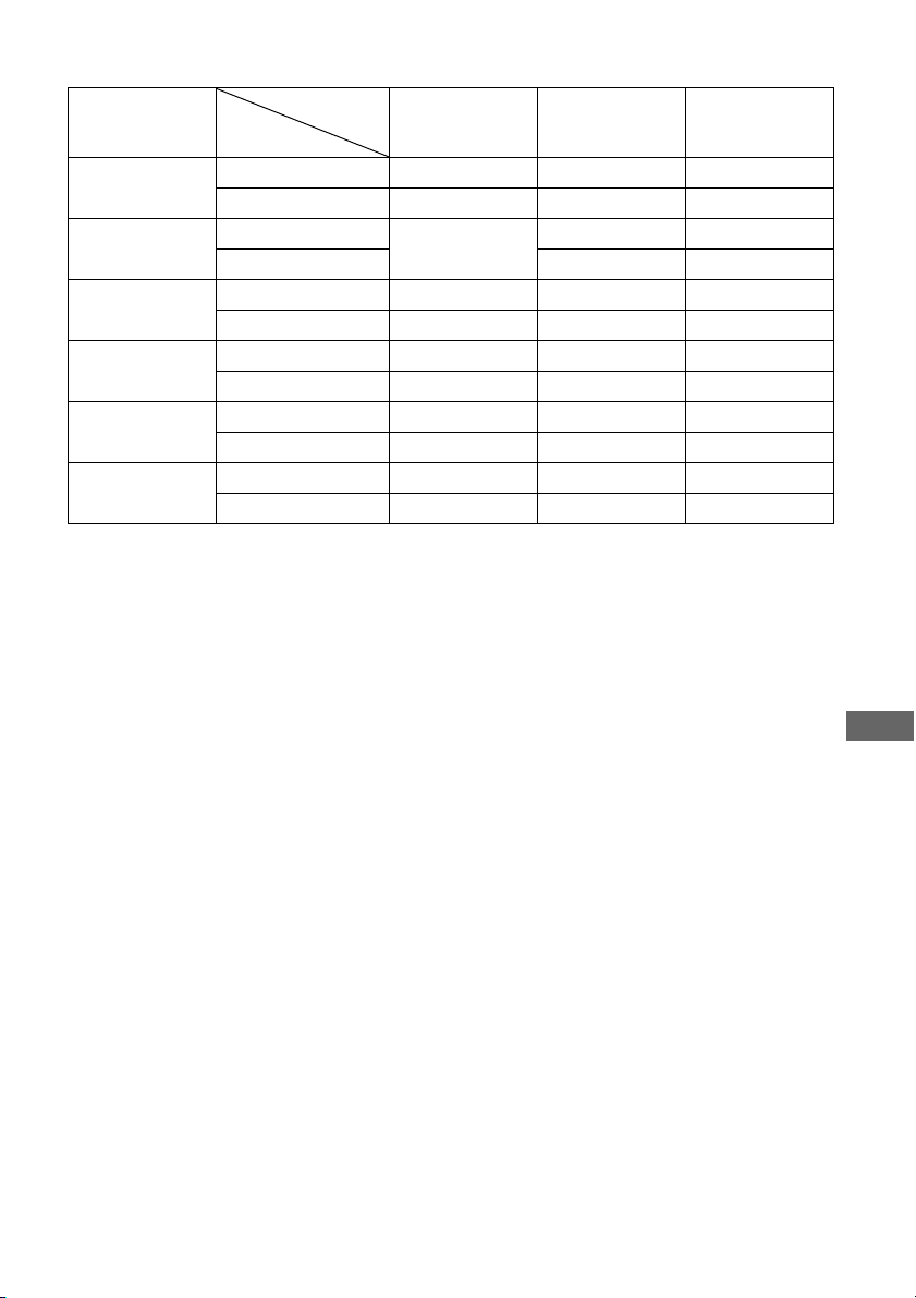
141
GB
Adjusting Settings
Figure 1
z : Video signals are converted and output through the video converter.
a : The same type of signal as that of the input signal is output. Video signals are not converted.
– : Video signals are not output.
a)The resolution is set automatically, depending on the connected monitor.
b)When the TV is connected to jacks other than the HDMI jacks, 480i/576i signals are output when
“Resolution” is set to “AUTO.”
c)480p/576p signals are output even if 480i/576i is set.
d)Video signals without copyright protection are output based on the settings menu. Video signals with
copyright protection are output as 480p.
Notes
• Video signals are not output from the COMPONENT VIDEO MONITOR OUT or MONITOR VIDEO OUT
jacks when the monitor, etc., is connected to HDMI OUT jacks.
• If you select a resolution that the connected TV does not support in the “Resolution” menu, the images from
the TV cannot be output correctly.
• Converted HDMI image output signals do not support “x.v.Color.”
• Converted HDMI image output signals do not support Deep Color.
“Resolution”
menu setting
HDMI OUT jacks MONITOR
COMPONENT
VIDEO OUT jacks
MONITOR VIDEO
OUT jack
DIRECT Component video – a –
Composite video – – a
AUTO
(initial setting)
Component video
z
a)
z
b)
z
b)
Composite video z
b)
z
b)
480i/576i Component video z
c)
zz
Composite video z
c)
zz
480p/576p Component video zz –
Composite video zza
720p, 1080i Component video zz
d)
–
Composite video zz
d)
a
1080p Component video za –
Composite video z – a
Input signals
Output from

142
GB
HDMI settings
Makes the required settings for components
connected to the HDMI jacks.
Lets you turn the function which controls
components connected to the HDMI jack
using an HDMI cable on or off.
x OFF
x ON
Note
When you set “Control for HDMI” to “ON,” “Audio
Out” may be changed automatically.
For European model
When “Control for HDMI” is turned on and
off, the H.A.T.S. (High quality digital Audio
Transmission System) function turns on and
off in conjunction with the “Control for
HDMI” function. When the H.A.T.S. function
is on, the sound quality is enhanced because
there is no jitter (timing gaps when reading
signals) when transmitting digital audio
signals.
Notes
• It takes some time to output the sound after a
playback operation is performed on the connected
component (e.g., pressing the PLAY button,
pressing the STOP button, pressing the PAUSE
button) due to limitations of the H.A.T.S. system.
The time lag depends on the sound source. This
feature may be ineffective depending on the
component and the sound source, even if you set it
to ON.
• The components connected to the HDMI jack must
support the H.A.T.S. feature.
• When “Audio Out” is set to “TV+AMP,” the
H.A.T.S. function may not work depending on the
component connected or the status of that
component. In this case, select “AMP” for “Audio
Out.”
• The H.A.T.S. function of this receiver works when
a Sony SCD-XA5400ES is connected to the
receiver.
Stream information about the
H.A.T.S. function available
Lets you output the HDMI signals to the TV
even when the receiver is in standby mode. For
details, see “Outputting the HDMI signals
even when the receiver is in standby mode
(Pass Through)” (page 117).
x OFF
x AUTO
x ON
Note
When “Control for HDMI” is set to “OFF,” you
cannot set “Pass Through.”
Lets you set the HDMI audio signals output
from the playback component connected to the
receiver via an HDMI connection.
x TV+AMP
The sound is output from the TV speaker and
the speakers connected to the receiver.
Control for HDMI
Audio signal input Sampling frequency
Linear PCM 2ch 44.1 kHz, 48 kHz,
88.2 kHz, 96 kHz,
176.4 kHz, 192 kHz
Linear PCM Multi 44.1 kHz, 48 kHz,
88.2 kHz, 96 kHz,
176.4 kHz, 192 kHz
DSD 2.8224 MHz
Pass Through
Audio Out (Setting HDMI audio
input)

143
GB
Adjusting Settings
Notes
• The sound quality of the playback component
depends on the TV’s sound quality, such as the
number of channels, and the sampling frequency,
etc. When the TV has stereo speakers, the sound
output from the receiver is also stereo as that of the
TV, even if you play multi-channel source.
• When you connect the receiver to a video
component (projector, etc.), sound may not be
output from the receiver. In this case, select
“AMP.”
• When you select the input that you have assigned
the HDMI input, sound does not output from the
TV.
x AMP
The HDMI audio signals from the playback
component is only output to speakers
connected to the receiver. The multi-channel
sound can be played back as it is.
Note
Audio signals are not output from the the TV
speaker when “Audio Out” is set to “AMP.”
Lets you turn the “24p Auto Sound Sync”
function on or off. This allows HD-D.C.S. to
be selected as the optimum sound field
automatically when 24p (24 frames per
second) signals are input from a playback
component, such as a Blu-ray Disc Player.
x ON
x OFF
Note
When “Control for HDMI” is set to “ON,”
depending on the player, the sound field may not
switch to HD-D.C.S.
When “Control for HDMI” is set to “ON,” the
receiver detects the 24p signals via “BRAVIA”
Sync. Therefore, if a player that is not compatible
with “BRAVIA” Sync sends out 24p signals, the
receiver will not switch the sound field to HD-
D.C.S. In this case, set “Control for HDMI” to
“OFF.” When “Control for HDMI” is set to “OFF,”
the receiver detects the 24p signals by itself.
Lets you set the level of the subwoofer to 0 dB
or +10 dB when PCM signals are input via an
HDMI connection. You can set the level for
each HDMI input independently.
x 0 dB
x AUTO
Automatically sets the level to 0 dB or +10 dB
depending on the frequency.
x +10 dB
Lets you output the video input signals from
the HDMI IN jack directly to the HDMI OUT
jack.
x OFF
The input signals from the HDMI IN jack are
output through a video processor.
x ON
The input signals from the HDMI IN jack are
output directly.
24p Auto Sound Sync
Subwoofer Level
Video Direct

144
GB
Network settings
Makes the settings for the network.
Lets you make the network settings.
To check the network settings
1
Press V/v repeatedly to select
“Network Setup,” then press .
2 Press V/v repeatedly to select
“Network Information,” then press .
The network setting information of the
receiver is displayed on the TV screen.
To configure network settings
automatically
1
Press V/v repeatedly to select
“Network Setup,” then press .
2 Press V/v repeatedly to select “Internet
Setup,” then press .
3 Press V/v repeatedly to select
“Connect Automatically (DHCP),” then
press .
“Success! The receiver is now connected to
network.” appears on the TV screen.
4 Press to select “Finish.”
To set the IP address manually
1
Press V/v repeatedly to select
“Network Setup,” then press .
2 Press V/v repeatedly to select “Internet
Setup,” then press .
3 Press V/v repeatedly to select “Manual
Configuration,” then press .
The setting screen for the IP address
appears on the TV screen.
4 Press to select the IP address.
The soft keyboard appears on the TV
screen.
5 Press V/v/B/b and to select a
character one by one to enter the IP
address.
6 Press V/v/B/b to select “Finish,” then
press .
7 Press b to display the next screen.
8 Repeat the process in steps 4 to 7
again to enter the Subnet Mask,
Gateway address, DNS1 address, and
DNS2 address.
9 Press V/v to select “Test Connection,”
then press .
“Success! The receiver is now connected to
network.” appears on the TV screen.
10Press to select “Finish.”
To set the Proxy server
manually
1
Press V/v repeatedly to select
“Network Setup” then press .
2 Press V/v repeatedly to select “Proxy
Setup,” then press .
3 Press V/v repeatedly to select
“Enable,” then press .
4 Press .
The soft keyboard appears on the TV
screen.
5 Press V/v/B/b and to select a
character one by one to enter the proxy
server address.
6 Press V/v/B/b repeatedly to select
“Finish,” then press .
7 Press b to select the Port number box,
then press .
The soft keyboard appears on the TV
screen.
Network Setup

145
GB
Adjusting Settings
8 Press V/v/B/b and to select a
character one by one to enter the port
number.
9 Press V/v/B/b repeatedly to select
“Finish,” then press .
10Press b.
11Press V/v repeatedly to select “Finish,”
then press .
Lets you enter the Rhapsody Account number
to listen to the Rhapsody Internet radio
service. For details, see “Setting an account”
(page 98). Rhapsody is only available in the
US.
Quick Click settings
Controls components connected to the receiver
using the on-screen remote.
Selects the source component that is to be
operated.
x Preset Mode
Customizes the remote to match the source
components connected to your receiver.
x Learn Mode
Allows the remote learn codes.
x Reset
Resets both programmed codes and learned
codes.
Selects the common component such as a TV,
projector or lights that is to be operated.
x Preset Mode
Customizes the remote to match the common
components such as the TV, the projector and
the lightings connected to your receiver.
x Learn Mode
Allows the remote to learn codes.
x Reset
Resets both programmed codes and learned
codes.
Sets several commands in a sequential order as
a single command.
Rhapsody Account
Source Component
Common Component
Macro Setup
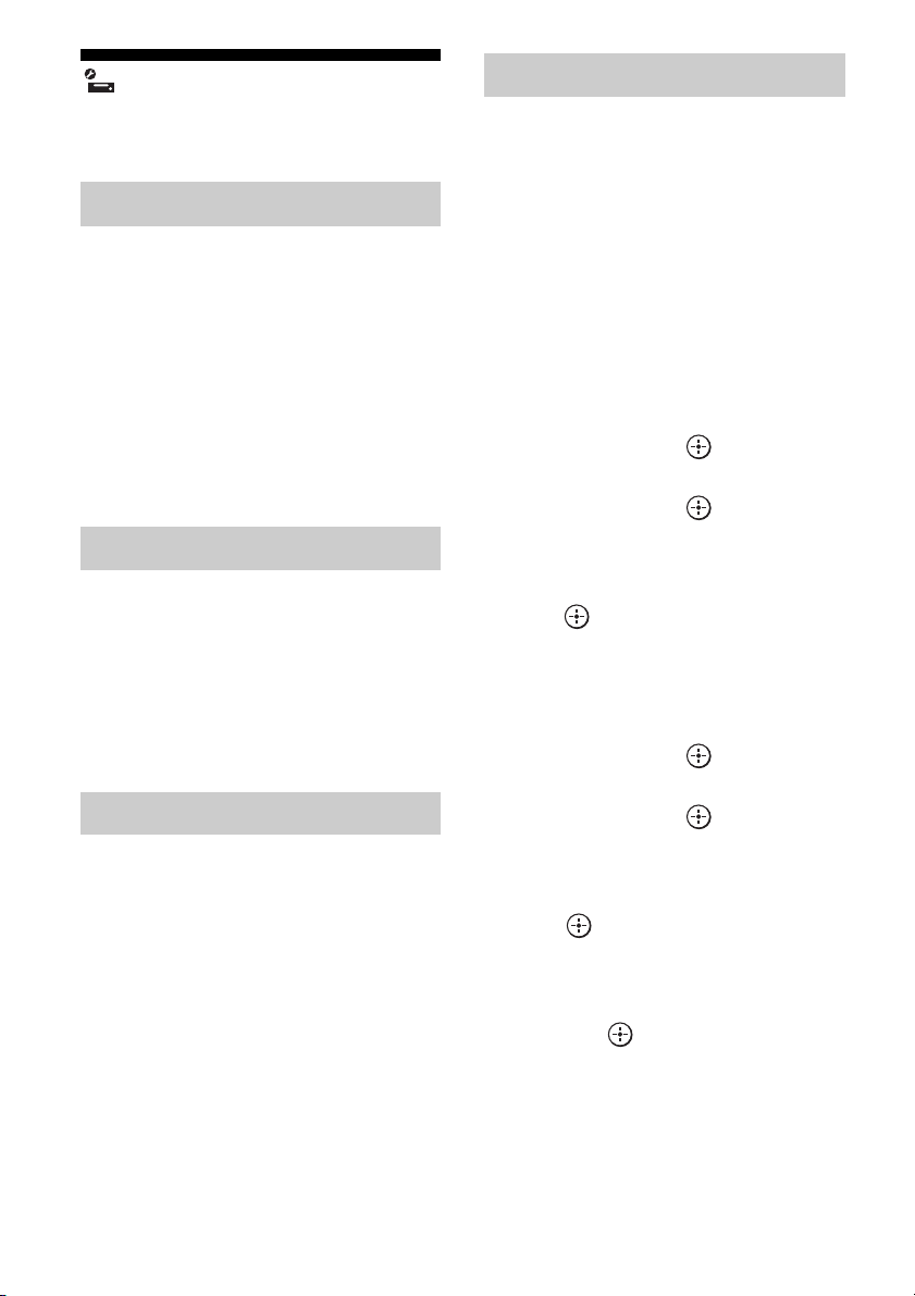
146
GB
System settings
Customizes the settings of the receiver.
Lets you activate the screen saver function for
the GUI menu on the TV connected to the
receiver.
x OFF
The screen saver function is disabled.
x ON
When there has been no operation attempted
for 15 minutes, the screen saver function is
activated automatically.
Selects the control mode for maintenance and
service.
x OFF
x RS232C
x Network
Selects the language for the messages on the
screen.
x English
x Español
x Français
x Deutsch
You can check the version of the firmware on
the system of the receiver, and you can also
update the firmware of the receiver.
You can also update the firmware of the
receiver using the ES Utility application
software provided on the CD-ROM supplied
with the receiver. For details, see “Updating
the receiver firmware using the ES Utility”
(page 103).
To check the system
information
1
Press V/v repeatedly to select “System
Update,” then press .
2 Press V/v repeatedly to select “Internet
Update,” then press .
The system information of the receiver
appears on the TV screen.
3 Press B/b to select “Cancel,” then
press .
To update the receiver using the
menu
1
Press V/v repeatedly to select “System
Update,” then press .
2 Press V/v repeatedly to select “Internet
Update,” then press .
The current system version and latest
system version are displayed on the TV
screen.
3 Press to select “Update.”
A confirmation screen appears on the TV
screen.
4 Press V/v repeatedly to select “Start,”
then press .
Receiver updating starts.
The MULTI CHANNEL DECODING
lamp on the front panel flashes while
updating.
When the updating complete, the receiver
will restart automatically.
Screen Saver
Installer Mode
Language
System Update
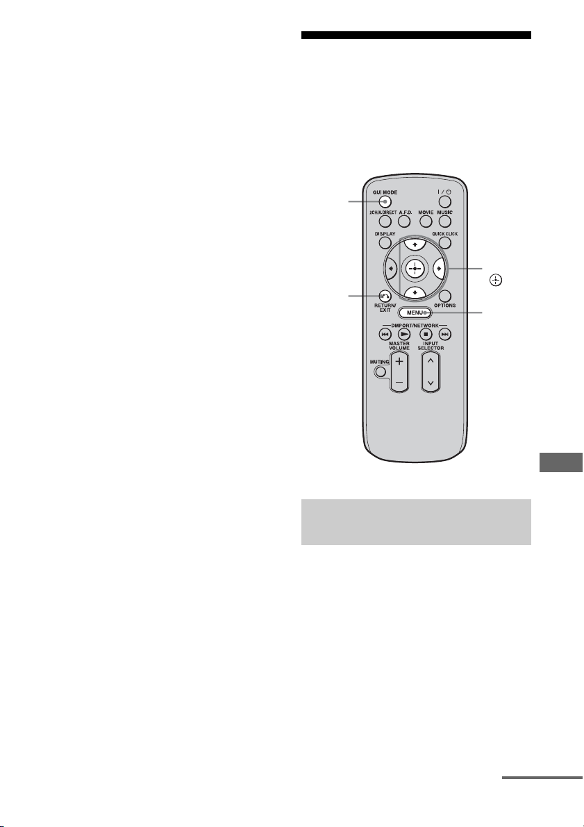
147
GB
Adjusting Settings
Notes
• In the following cases, a message appears on the
TV screen and the update of the receiver is not
performed.
– when all versions are the latest one.
– when the receiver cannot retrieve the data, such
as when the network has not been set up, or
when the server is down, etc.
• Do not turn the receiver off or disconnect the
network cable during firmware updating. It may
cause a malfunction.
• It may take 30 minutes for the firmware updating to
complete.
Operating without
connecting to a TV
You can operate the receiver using the display
window of the receiver even if the TV is not
connected to the receiver.
If “GUI MODE” is displayed in the display
window of the receiver when you press
MENU, DISPLAY, or V/v, press GUI MODE
to switch the display mode of the menu to
“DISPLAY MODE.” (After “GUI MODE
OFF” has appeared in the display window of
the receiver, the receiver is switched to
“DISPLAY MODE.”)
1 Turn on the receiver.
Using the menu in the display
window
RETURN/
EXIT O
V/v/b,
MENU
GUI
MODE
continued
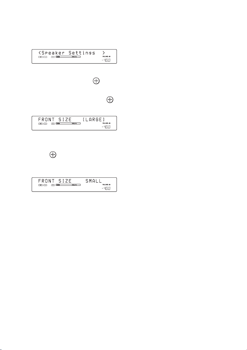
148
GB
2 Press MENU.
The menu is displayed in the display
window of the receiver.
Example: When you select “Speaker Settings”
3 Press V/v repeatedly to select
the menu, then press or b.
4 Press V/v repeatedly to select
the menu item, then press .
The parameter appears in brackets.
5 Press V/v repeatedly to select
the parameter you want, then
press .
The parameter is entered and the brackets
disappear from the display.
Tip
To return to the previous step, press RETURN/EXIT
O.
149
GB
Adjusting Settings
The following options are available in each menu.
“xx…” in the table signifies the parameter for each item.
Menu list (in the display window)
Menu Item Parameter Initial
setting
Auto Calibration AUTO CAL START?
5 4 3 2 1
MEASURING: TONE
MEASURING: T.S.P.
MEASURING: WOOFER
COMPLETE
[xxxxxxxxxx]
RETRY, SAVE EXIT, WRN CHECK,
PHASE INFO, DIST. INFO,
LEVEL INFO, EXIT
SAVE
EXIT
WARNING CODE [xxx:4x] FL, FR, C, SLA, SRA, SLB, SRB, SBL,
SBR : 0, 1, 2, 3, 4
NO WARNING
ERROR CODE [xxx:3x] F, SR, SB : 0, 1, 2, 3, 4
RETRY? [xxxx] YES, EXIT YES
CANCEL
CAL TYPE [xxxxxxxxx] ENGINEER, FULL FLAT,
FRONT REF, OFF
FULL
FLAT
POSITION [xxxxxxxx] POS.1, POS.2, POS.3 POS.
1
NAME IN ? [xxxxxxxx]
Level Settings TEST TONE [xxxxxxxx] OFF, L to SW (AUTO), L to SW (FIX) OFF
PHASE NOISE [xxxxxxx] OFF, L/C, C/R, R/SL, R/SR, SR/SL,
SR/SBR, SBR/SBL, SBL/SL, SL/L,
L/SR
OFF
PHASE AUDIO [xxxxxxx] OFF, L/C, C/R, R/SL, R/SR, SR/SL,
SR/SBR, SBR/SBL, SBL/SL, SL/L,
L/SR
OFF
FRONT L [xxx.xdB] –10.0dB to +10.0dB (0.5dB step) 0dB
FRONT R [xxx.xdB] –10.0dB to +10.0dB (0.5dB step) 0dB
CENTER [xxx.xdB] –20.0dB to +10.0dB (0.5dB step) 0dB
SURROUND L [xxx.xdB] –20.0dB to +10.0dB (0.5dB step) 0dB
SURROUND R [xxx.xdB] –20.0dB to +10.0dB (0.5dB step) 0dB
SUR BACK [xxx.xdB] –20.0dB to +10.0dB (0.5dB step) 0dB
SUR BACK L [xxx.xdB] –20.0dB to +10.0dB (0.5dB step) 0dB
SUR BACK R [xxx.xdB] –20.0dB to +10.0dB (0.5dB step) 0dB
SUB WOOFER [xxx.xdB] –20.0dB to +10.0dB (0.5dB step) 0dB
D. RANGE COMP. [xxx] OFF, AUTO, STD, MAX AUTO
continued

150
GB
Speaker Settings SP PATTERN [xxxxx] 2/0 to 3/4.1 (16 patterns) 3/4.1
FRONT SIZE [xxxxx] SMALL, LARGE LARGE
CENTER SIZE [xxxxx] SMALL, LARGE LARGE
SURROUND SIZE [xxxxx] SMALL, LARGE LARGE
SB ASSIGN [xxxxx] OFF, BI-AMP, ZONE2 OFF
FRONT L [xxxxxxxxx]
3’ 3” to 32’ 9” (1 inch step)
1.0 to 10.0 (m) (0.1 m step)
9’ 10”
3m
FRONT R [xxxxxxxxx]
CENTER [xxxxxxxxx]
SURROUND L
[xxxxxxxxx]
SURROUND R
[xxxxxxxxx]
SUR BACK [xxxxxxxxx]
SUR BACK L
[xxxxxxxxx]
SUR BACK R
[xxxxxxxxx]
SUB WOOFER
[xxxxxxxxx]
DISTANCE UNIT [xxxxx] meter, feet feet*
FR CROSSOVER** [xxxxx] 40 to 200 (10 Hz step) 120
CNT CROSSOVER**
[xxxxx]
40 to 200 (10 Hz step) 120
SUR CROSSOVER**
[xxxxx]
40 to 200 (10 Hz step) 120
CNT A.DOWN MIX [xxx]OFF, ON OFF
SP IMPEDANCE [xohm] 4ohm, 8ohm 8ohm
Menu Item Parameter Initial
setting
*
meter
f
or European mo
d
e
l
** You cannot select this setting when the speaker is set to “LARGE.”

151
GB
Adjusting Settings
Sur Settings SOUND FIELD SELECT ?
[xxxxxxxxxxxxxxx
xxx]
Sound Field AFD
AUTO
ENHANCED SUR SELECT?
[xxxxxxxxxxxxxxx
xxx]
PLII, PLIIx, Neo:6 Cinema, Neo:6
Music, NEURAL-THX PLIIx
EFFECT TYPE [xxxxxxx] DYNAMIC, THEATER, STUDIO THEATER
EQ Settings FRONT BASS [xxxdB] –10dB to +10dB (1 dB step) 0dB
FRONT TREBLE [xxxdB] –10dB to +10dB (1 dB step) 0dB
CENTER BASS [xxxdB] –10dB to +10dB (1 dB step) 0dB
CENTER TREBLE [xxxdB] –10dB to +10dB (1 dB step) 0dB
SUR/SB BASS [xxxdB] –10dB to +10dB (1 dB step) 0dB
SUR/SB TREBLE [xxxdB] –10dB to +10dB (1 dB step) 0dB
Tuner Settings FM MODE [xxxxxx] MONO, STEREO STEREO
NAME IN ? [xxxxxxxx]
FMxx [xxxxxxxx]
NAME IN ? [xxxxxxxx]
AMxx [xxxxxxxx]
XM ANTENNA AIMING*
XM RADIO ID DISPLAY*
PARENTAL LOCK* [xxx] YES, NO NO
LOCK CODE EDIT* 0000
SR ANTENNA AIMING*
SIRIUS ID DISPLAY*
Audio Settings D.L.L. [xxxx] OFF, AUTO AUTO
A/V SYNC [xxxxxxxxx] HDMI AUTO,
0ms to 300ms (10 ms step)
0ms
DUAL MONO [xxxxxxxx] MAIN/SUB, MAIN, SUB MAIN
DEC. PRIORITY [xxxx]PCM, AUTO AUTO
NIGHT MODE [xxx] ON, OFF OFF
AUDIO ASSIGN ?
Video Settings RESOLUTION
[xxxxxxxx]
DIRECT, AUTO, 480/576i, 480/576p,
720p, 1080i, 1080p
AUTO
VIDEO ASSIGN ?
Menu Item Parameter Initial
setting
*USA/Cana
di
an mo
d
e
l
on
l
y
continued

152
GB
To change the display
You can check the sound field, etc., by
changing the information on the display.
1 Select the input for which you want to
check the information.
2 Press DISPLAY repeatedly.
Each time you press DISPLAY, the display
will change as follows.
Input you selected t Sound field type t
Input name you entered ...
When listening to FM and AM radio
Station name t Frequency t Sound field
type...
Index name appears only when you have
assigned one to the input or preset station.
Index name does not appear when only
blank spaces have been entered.
When tuning in a channel from a satellite
tuner (USA/Canadian model only)
Channel name t Channel number t
Category t Artist name t Song title t
Composer name (SIRIUS only) t Signal
strength t Sound field type
When receiving RDS broadcasts (European
model only)
PS (Program Service name)
a)
, Preset name,
Band, or Preset number t Frequency,
band and preset number t PTY (Program
Type) indication
b)
t RT (Radio Text)
indication
c)
t Sound field type
a)This information also appears for non-RDS
FM stations.
b)Type of program being broadcast
c)Text messages sent by the RDS station.
HDMI Settings CTRL FOR HDMI [xxx]OFF, ON OFF
PASS THROUGH [xxxx] OFF, AUTO, ON OFF
AUDIO OUT [xxxxxx] TV+AMP, AMP AMP
24p SOUND SYNC [xxx] OFF, ON OFF
SW LEVEL [xxxdB] AUTO, +10dB, 0dB AUTO
VIDEO DIRECT [xxx]OFF, ON OFF
System Settings NAME IN ? [xxxxxxxx]
PARTY SETUP [xxxxxxx] ZONE2/3, ZONE2, ZONE3 ZONE2/3
12V TRIG. MAIN [xxxxx] OFF, CTRL, ZONE, INPUT, HDMI A,
HDMI B
OFF
12V TRIG. ZONE2 [xxxxx] OFF, CTRL, ZONE, MAIN OFF
12V TRIG. ZONE3 [xxxxx] OFF, CTRL, ZONE, MAIN OFF
INSTALLER MODE [xxxx] OFF, 232C, NET OFF
VERSION [x.xxx]– –
Menu Item Parameter Initial
setting
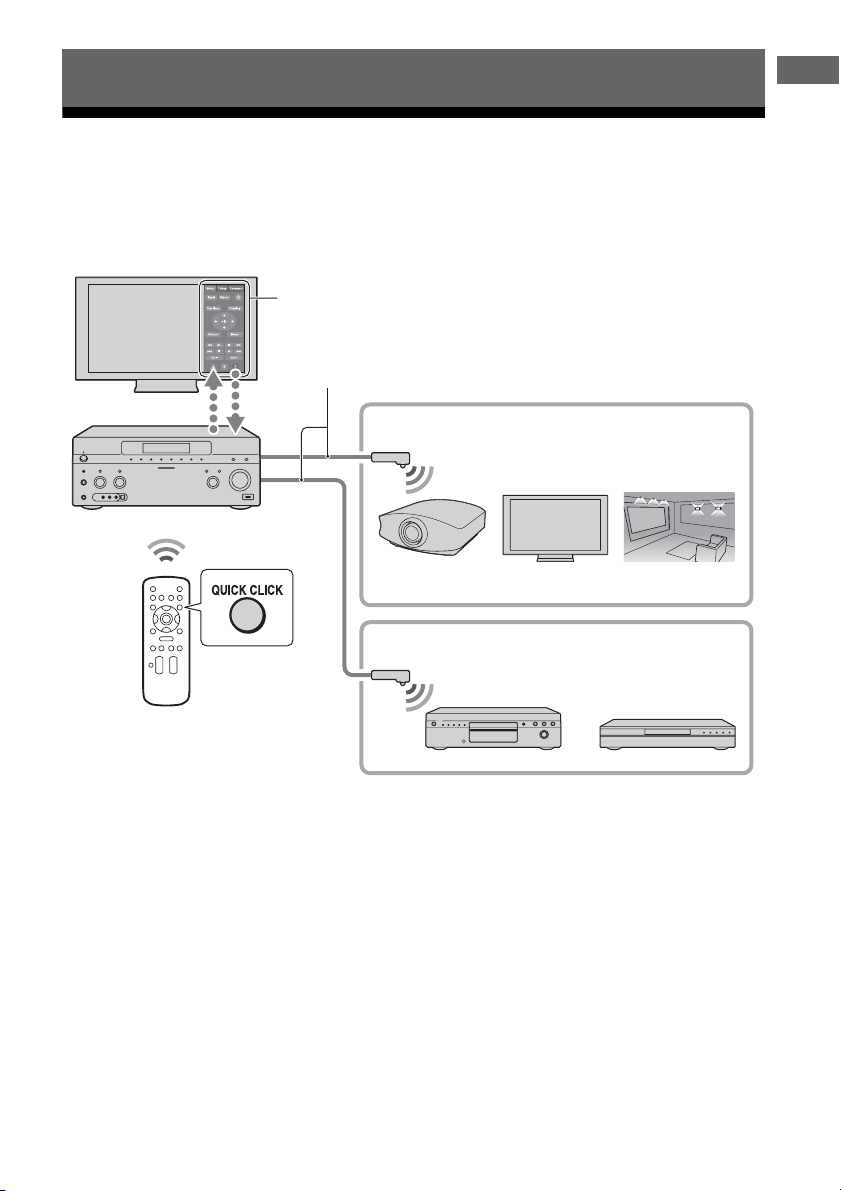
153
GB
Operating Each Component Using the On-screen Remote (Quick Click)
Operating components or lighting connected to the
receiver using the on-screen remote (Quick Click)
You can control components connected to the receiver, a projector, and the light control unit using
the on-screen remote on the TV screen.
Operating Each Component Using the On-screen Remote (Quick Click)
On-Screen remote (Quick Click)
IR Blaster
Common Components
Projector
Source Components
TV Light
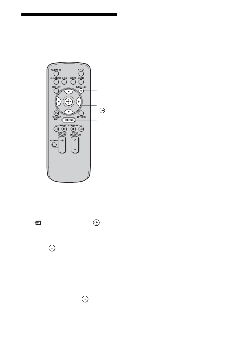
154
GB
Using Quick Click
You can control components connected to the
receiver, a TV, projector, or lighting using the
on-screen remote on the TV screen.
1 Press MENU.
The menu is displayed on the TV screen.
2 Press V/v repeatedly to select
“ Input,” then press or b.
3 Press V/v repeatedly to select
the component you want, then
press .
4 Press QUICK CLICK.
5 Press V/v/B/b repeatedly to
select the appropriated buttons
on the on-screen remote to use
the function listed in the table
below, then press .
Note
You may not be able to operate some functions for
the components you are using.
QUICK
CLICK
V/v/B/b,
MENU
155
GB
Operating Each Component Using the On-screen Remote (Quick Click)
Table of buttons used to control each component (Quick Click)
See “Operating the components connected to the receiver” for details on the buttons of the on-
screen remote.
Category
Button
TV VCR PROJECTOR BD/DVD LD CD MD CABLE SAT TAPE DVR LIGHT
1
zz z zzzzzzzzz
10 key
zz – zzzzzzzz
+10 (•)
z ––zzzzzz – z
Ent
zz – zzzzzzzz
Input
zzzz–––zz – z
Display (Info)
zz z zzzzzzzz
Top Menu (Guide)
z ––z –––zz – z
m
/
N
/
M
/
x
/
X
– z – zzzzzzzz
z
– z – z ––zzzzz
.
/
>
–– – zzzzzzzz
V
/
v
/
B
/
b
/Menu/
/Exit/Return
zzzz–––zz – z
Ch +/–
zz – ––––zz – z –
A/B/C
–– – ––––z ––––
Scene 1-16
z
All On/Off
z
On/Off
z
Raise/Lower
z
Light Off
z
Tog gle
z
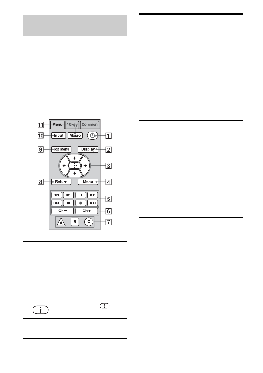
156
GB
You can control components connected to the
receiver using the “Menu” and “10 key”
features of Quick Click.
The following explanation provides examples
of normal operation. The component may
work differently, or may not work at all
depending on the component.
Menu tab
Operating the components
connected to the receiver
Button Function
A 1 Select to turn components
connected to the receiver on or
off.
B Display
(Info)
Select to display the current
status of or information on
components connected to the
receiver.
C V/v/B/b, Select V/v/B/b to select menu
items. Then press to enter
the selection.
D Menu Select to display the menu of
components connected to the
receiver.
E N, z Select to start playback or to
record.
x, X Select to stop or pause playback
or recording.
m/M Select to fast-forward or fast-
backward.
./> Select to jump to the next/
previous track.
F Ch+/Ch– Select Ch +/– to select the
channel of the TV, satellite
tuner, VCR, etc.
G A/B/C Select when you operate a
cableTV tuner.
H Return (Exit) Select to return to the previous
menu or exit the menu.
I Top Menu
(Guide)
Select to display the top menu
of the DVD player or Blu-ray
Disc Player, etc or display the
program guide of a TV, satellite
tuner or hard disk recorder, etc.
J Input Select the input source of the
components connected to the
receiver.
K Macro Select to start a macro
programmed with Quick Click.
When there are no programmed
macros, this button does not
appear.
Button Function
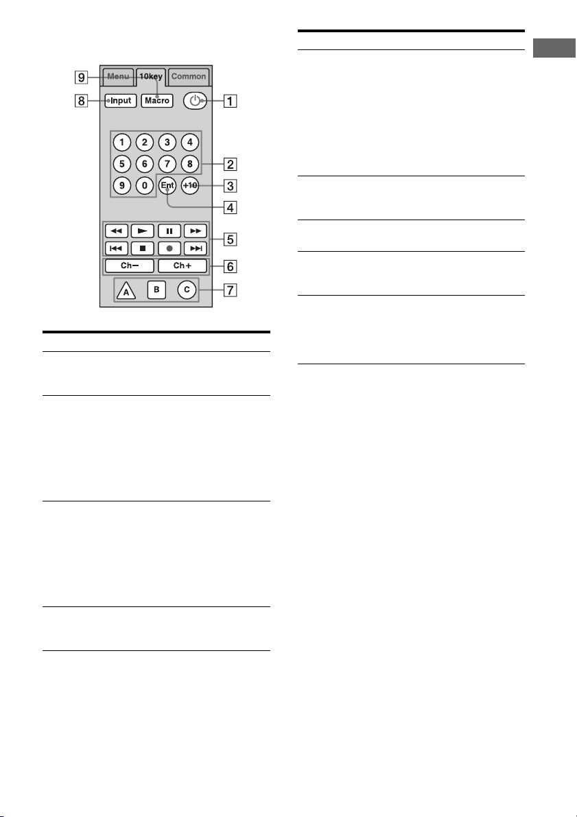
157
GB
Operating Each Component Using the On-screen Remote (Quick Click)
10 key tab
Button Function
A 1 Select to turn components
connected to the receiver on or
off.
B 10 key Select to
– select track numbers of the
CD player, DVD player,
Blu-ray Disc Player, or MD
deck.
– select channel numbers of
the TV, Satellite tuner or the
VCR.
C +10 (.) Select to
– select track numbers over 10
of the CD player, DVD
player, Blu-ray Disc Player,
or MD deck.
– select channel numbers over
10 of the TV, Satellite tuner
or the VCR.
D Ent Press to enter the value after
selecting a channel, disc or
track using the numeric buttons.
E N, z Select to start playback or to
record.
x, X Select to stop or pause playback
or recording.
m/M Select to fast-forward or fast-
backward.
./> Select to jump to the next/
previous track.
F Ch+/Ch– Select Ch +/– to select the
channel of the TV, satellite
tuner, VCR, etc.
G A/B/C Select when you operate a
cableTV tuner.
H Input Select the input source of
components connected to the
receiver.
I Macro Select to start a macro
programmed with Quick Click.
When there are no programmed
macros, this button does not
appear.
Button Function
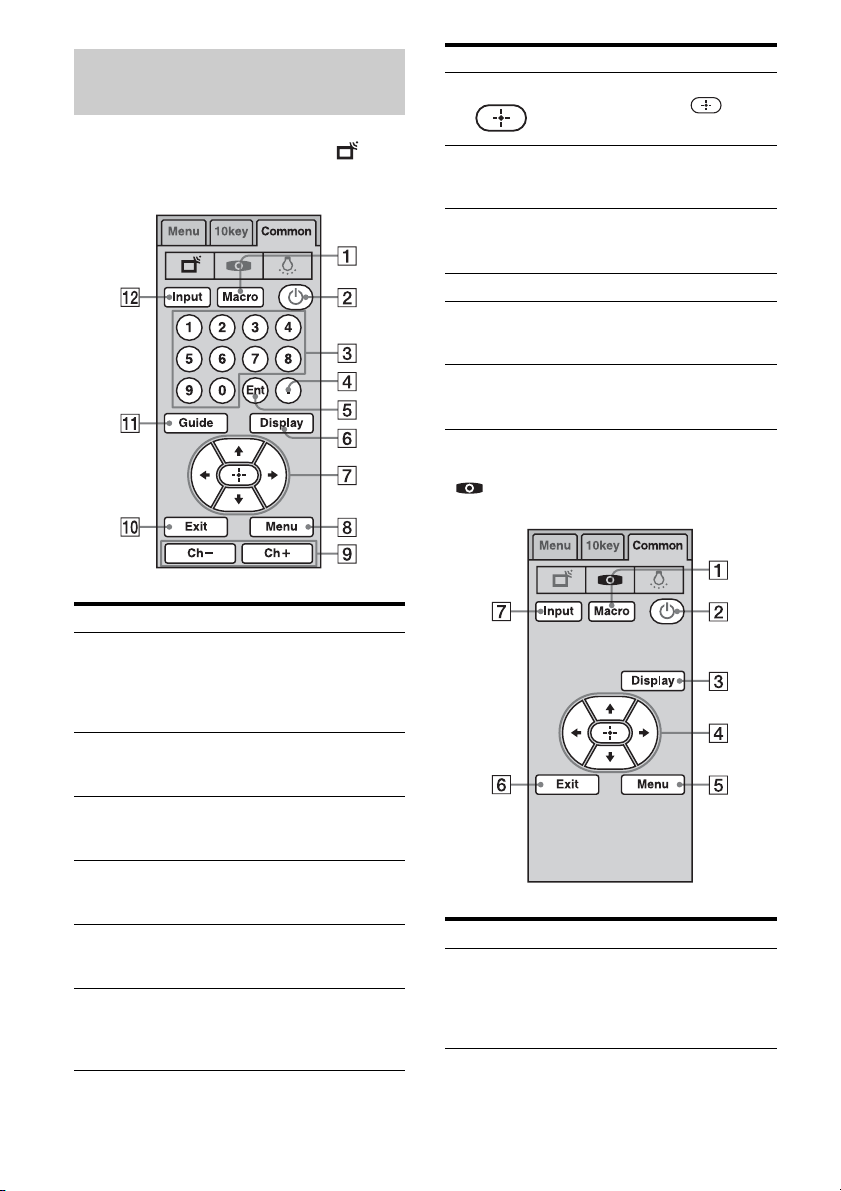
158
GB
To operate the TV, select ( ) on
Common tab.
To operate the projector, select
( ) on Common tab.
Operating the TV, projector or
lighting
Button Function
A Macro Select to start a macro
programmed with Quick Click.
When there are no programmed
macros, this button does not
appear.
B 1 Select to turn components
connected to the receiver on or
off.
C 10 key Select to select channel
numbers of the TV, Satellite
tuner or the VCR.
D . (+10) Select to select channel
numbers over 10 of the TV,
Satellite tuner or the VCR.
E Ent Press to enter the value after
selecting a channel, disc or
track using the numeric buttons.
F Display
(Info)
Select to display the current
status of or information on
components connected to the
receiver.
G V/v/B/b, Select V/v/B/b to select menu
items. Then press to enter
the selection.
H Menu Select to display the menu of
the components connected to
the receiver.
I Ch+/Ch– Select Ch +/– to select the
channel of the TV, satellite
tuner, VCR, etc.
J Exit Select to exit the menu.
K Guide Select to display the program
guide of a TV, satellite tuner,
hard disk recorder, etc.
L Input Select the input source of the
components connected to the
receiver.
Button
Function
A Macro Select to start a macro
programmed with Quick Click.
When there are no programmed
macros, this button does not
appear.
Button Function

159
GB
Operating Each Component Using the On-screen Remote (Quick Click)
To operate the lighting, select
( ) on Common tab.
* A lighting control unit is a device which can adjust
the brightness of two or more lights with a one-
touch operation.
Consult your installation dealer about lighting
control unit installation.
To make the on-screen remote
disappear
Press QUICK CLICK or RETURN/EXIT O.
B 1 Select to turn components
connected to the receiver on or
off.
C Display
(Info)
Select to display the current
status of or information on
components connected to the
receiver.
D V/v/B/b, Select V/v/B/b to select menu
items. Then press to enter
the selection.
E Menu Select to display the menu of
components connected to the
receiver.
F Exit Select to exit the menu.
G Input Select the input source of the
components connected to the
receiver.
Button Function
A Light Off Select to turn off the power of
the lighting control unit.*
B Scene 1~16 Select to select a preset lighting
pattern.
Button
Function
C All Off Select to turn down the
brightness of all the lights to the
minimum (putting out the
lights).
D Off Select to turn off a single light.
E Lower Select to turn down the
brightness of all the lights at the
same time.
F Toggle Select to switch the preset
lighting pattern.
G Raise Select to turn up the brightness
of all the lights at the same time.
H On Select to turn on a single light.
I All On Select to turn up all the lights to
maximum brightness.
J Macro Select to start a macro
programmed with Quick Click.
When there are no programmed
macros, this button does not
appear.
Button Function
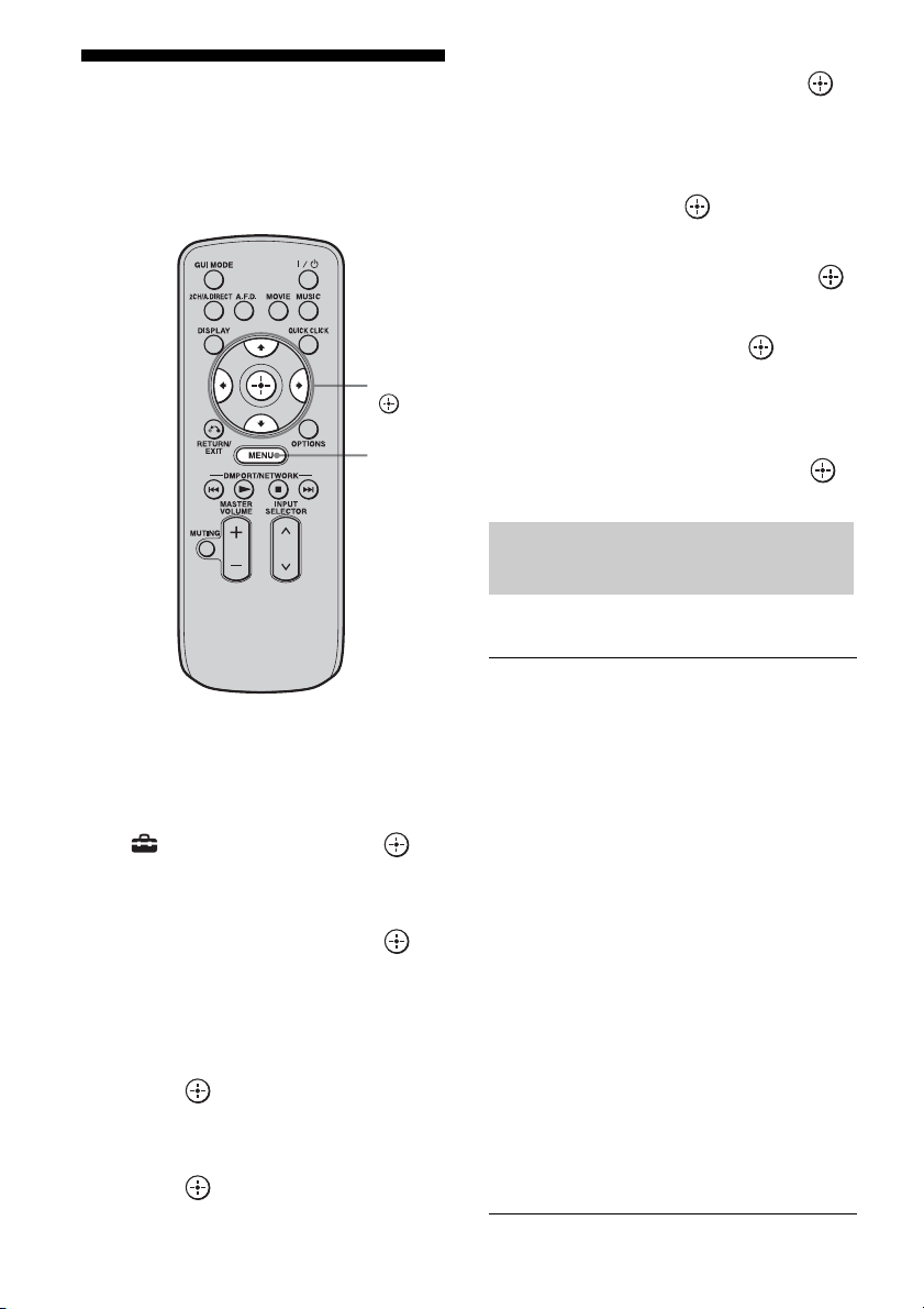
160
GB
Setting components that
are operated by the on-
screen remote
1
Press MENU.
The menu is displayed on the TV screen.
2 Press V/v repeatedly to select
“ Settings,” then press or
b.
3 Press V/v repeatedly to select
“Quick Click,” then press or
b.
4 Press V/v repeatedly to select
“Source Component,” or
“Common Component,” then
press .
5 Press V/v repeatedly to select
the component you want, then
press .
6 Press V/v repeatedly to select
“Preset Mode,” then press .
7 Press V/v repeatedly to select
the input (including a TV) for
the component you want to set
up, then press .
8 Press V/v repeatedly to select
the maker name, then press .
9 Press V/v repeatedly to select
the code, then press .
If you want to have a test, select “Play” on
the TV screen.
10Press V/v/B/b repeatedly to
select “Finish,” then press .
TV (for USA/Canadian model)
V/v/B/b,
MENU
The maker list of the
corresponding component
SONY ABEX
ADMIRAL ADVENT
ADVENTURA AIWA
AKAI A MARK
ANAM AOC
APEX ARCHER
AUDINAC AUDIOVOX
BELL & HOWELL BROKSONIC
CANDLE CCE
CINERAL CITIZEN
COBY CRAIG
CROSLEX CROWN
CTX CURTIS MATHIS
DAEWOO DAYTRON
DUKANE DURABRAND
EMERSON EMPREX
ESA FISHER
FUJITSU FUNAI
GE GOLDSTAR
GRADIENTE HAIER
HITACHI HP
ILO INSIGNIA
JANEIL JC PENNEY

161
GB
Operating Each Component Using the On-screen Remote (Quick Click)
TV (for European model)
Projector
VCR (for USA/Canadian model)
JENSEN JVC
KLOSS KLOSS NOVABEAM
KONKA KTV
LG LXI
MAGNAVOX MARANTZ
MAXENT MEGATRON
MEMOREX MGA
MINUTZ MITSUBISHI
MOTOROLA NAD
NEC NOBLEX
NORCENT OLEVIA
OPTIMUS OPTONICA
ORION PANASONIC
PHILCO PHILIPS
PIONEER POLAROID
PORTLAND PRINCETON
PROSCAN PROTON
PROTRON PROVIEW
QUASAR RADIO SHACK
RCA REALISTIC
RUNCO SAMPO
SAMSUNG SANSUI
SANYO SCOTT
SEARS SEMP TOSHIBA
SERIE DORADA SHARP
SIGNATURE 2000 SOUNDESIGN
SPECTRICON SUPREMACY
SVA SYLVANIA
SYMPHONIC SYNTAX BRILLIAN
TANDY TATUNG
TECHWOOD TEKNICA
TERA TOSHIBA
TRUTECH UNIVERSAL
VIDECH VIEWSONIC
VIKING VISCO
VIZIO WARDS
WESTINGHOUSE ZENITH
ZONDA
SONY AIWA
AKAI AUDIO SONIC
B&O BLAUPUNKT
BRIONVEGA BUSH
CROWN DAEWOO
DUAL FENNER
FERGUSON GOLDSTAR
GOODMANS GRUNDIG
HANSOL HITACHI
HOHER HYPER
INNO-HIT IRRADIO
JVC KENDO
LG LOEWE
LUXOR MARK
MATSUI MITSUBISHI
MIVAR MIVER
NEC NOKIA
NOKIA OCEANIC NORDMENDE
OKANO ORION
PANASONIC PHILIPS
PIONEER ROADSTAR
SABA SABA, TELEFUNKEN
SAMSUNG SANYO
SCHNEIDER SELECO
SHARP TELEFUNKEN
THOMSON TOSHIBA
UNITED VIETA
SONY EPSON
MITSUBISHI OLYMPUS
OPTOMA RUNCO
SHARP
SONY ADMIRAL
AIWA AKAI
AUDIO DYNAMICS BELL & HOWELL
BROKSONIC CANON
CCE CINERAL
CINEVISION CITIZEN
CRAIG CURTIS MATHIS
DAEWOO DBX
DIMENSIA EMERSON
FISHER FUNAI
GE GO VIDEO
GOLDSTAR GRADIENTE
HITACHI HQ
INSIGNIA INSTANT REPLAY
JC PENNY JVC
KENWOOD LG
LITE-ON LXI
MAGNAVOX MARANTZ
MARTA MEMOREX
continued

162
GB
VCR (for European model)
BD/DVD player (for USA/
Canadian model)
BD/DVD player (for European
model)
LD player
MGA MINOLTA
MITSUBISHI MULTITECH
NEC NOKIA
OLYMPIC OPTIMUS
ORION PANASONIC
PENTAX PHILCO
PHILIPS PIONEER
PROSCAN QUASAR
RCA REALISTIC
SAMSUNG SANSUI
SANYO SCOTT
SEARS SEMP TOSHIBA
SENSORY SCIENCE SHARP
SHINTOM SIGNATURE 2000
SINGER SYLVANIA
SYMPHONIC TASHIRO
TATUNG TEAC
TECHNICS TOSHIBA
WARDS YAMAHA
ZENITH
SONY AIWA
AKAI CGM
FENER FUNAI
GOLDSTAR GRUNDIG
HITACHI JVC
LOEWE NOKIA
NORDMENDE OKANO
PANASONIC PHILIPS
PHONOLA SAMSUNG
SANYO SELECO
SHARP SIEMENS
TELEFUNKEN TOSHIBA
W.W.HOUSE WATSON
SONY ADVENT
AIWA APEX
BROKSONIC CINEVISION
CLASSIC COBY
CYBER HOME DAEWOO
DENON EMERSON
FUNAI GO VIDEO
GPX HARMAN/KARDON
HITACHI HUMAX
ILO INSIGNIA
JVC KENWOOD
KLH KOSS
KRELL LG
LITE-ON MAGNAVOX
MARANTZ MITSUBISHI
NORCENT TECHNOLOGY
ONKYO
OPTOMA ORION
ORITRON PANASONIC
PHILIPS PIONEER
RCA SAMSUNG
SANSUI SANYO
SHARP SHINCO
SYLVANIA SYMPHONIC
TEAC TERAPIN
THOMSON TOSHIBA
YAMAHA ZENITH
SONY AIWA
BOSE CAT
CHESTRON CYBERHOME
D.I.K. DAEWOO
DENON ELTA
GRUNDIG HARMAN/KARDON
HITACHI JAMO
JVC KENWOOD
KLH MATSUI
MITSUBISHI MUSTEK
NAKAMICHI ONKYO
PANASONIC PHILIPS
PIONEER PRIMAS
RCA SAMSUNG
SHARP SHINCO
SYLVANIA TEAC
THOMSON TOSHIBA
YAMAHA/DENON ZENITH
SONY HITACHI
KENWOOD MAGNAVOX
PANASONIC PHILIPS
PIONEER SANYO
SHARP

163
GB
Operating Each Component Using the On-screen Remote (Quick Click)
CD player (for USA/Canadian
model)
CD player (for European model)
MD deck
Cable box
Satellite tuner (box) (for USA/
Canadian model)
Satellite tuner (box) (for
European model)
SONY ADMIRAL
AIWA AKAI
B&O CROWN
DAEWOO DENON
EMERSON FISHER
GOLDSTAR HARMAN/KARDON
HITACHI INSIGNIA
JENSEN JVC
KENWOOD LG
MAGNAVOX MARANTZ
MCINTOSH NAD
NAKAMICHI ONKYO
OPTIMUS PANASONIC
PHILIPS PIONEER
RCA SABA
SAMSUNG SANSUI
SANYO SCHNEIDER
SHARP SHERWOOD
SOUNDESIGN T+A
TECHNICS TOSHIBA
YAMAHA
SONY AIWA
CARVER DAEWOO
DENON FISHER
GRUNDIG HARMAN
HITACHI JVC
KENWOOD LG
NAD NAKAMICHI
ONKYO PANASONIC
PHILIPS PIONEER
QUADRAL SABA
SAMSUNG SANYO
SHERWOOD SHERWOOD
TECHNICS UHER
YAMAHA
SONY AIWA
AKAI DENON
JVC KENWOOD
MARANTZ ONKYO
PANASONIC PIONEER
SANSUI SHARP
TEAC YAMAHA
SONY ABC
ADELPHIA
ADVANCED NEWHOUSE
ALTRIO AMERICAST
ATLANTIC BROADBAND
BELL SOUTH
BLUE RIDGE BRIGTH HOUSE
CABLEVISION CHARTER
COMCAST COX
GENERAL INSTRUMENT
GNC
HAMLIN ILLICO
JERROLD MEMOREX
MOTOROLA NET
OAK PACE
PANASONIC PARAGON
PHILIPS PIONEER
PULSAR REGAL
RODGERS RUNCO
SCIENTIFIC ATLANTA
SEREN
SIGECOM SUSQUEHANNA
TIME WARNER TOCOM
TOSHIBA VIDEOTRON
WIDEOPENWEST ZENITH
SONY CROSSDIGITAL
DIRECTV DISH NETWORK
ECHOSTAR GE
GENERAL INSTRUMENT
HITACHI
HUGHES HUMAX
JVC MAGNAVOX
MEMOREX PANASONIC
PAYSAT PHILIPS
PROSCAN RCA
SAMSUNG STAR SIGHT
SYLVANIA TOSHIBA
UNIDEN USDIGITAL
SONY AMSTRAD
AMSTRAD/RADIX B SKY B
CANAL + GALAXIS
continued

164
GB
Lighting control
Tape deck (for USA/Canadian
model)
Tape deck (for European model)
Digital Video Recorder
GOLD BOX GRUNDIG
HYUNDAI JERROLD
KATHREIN MATSUI
NIKKO NOKIA
NTV PLUS 2000 PACE
RADIX SABA
SABA/THOMSON SKY MASTER
TECHNISAT WATSON
ZEHNDER
LUTRON(Grafik Eye)
LUTRON(HomeWorks)
LUTRON(RadioRA)
LUTRON(Sivoia Shades)
LUTRON(Spacer)
LUTRON(Spacer System)
X10
SONY AIWA
DENON FISHER
GOLDSTAR HARMAN/KARDON
JVC KENWOOD
LG MARANTZ
NAD NAKAMICHI
ONKYO PANASONIC
PHILIPS PIONEER
RCA SANSUI
SANYO SHARP
TEAC TECHNICS
YAMAHA
SONY AIWA
AKAI B&O
DENON HARMAN
JVC KENWOOD
LG MARANTZ
MATSUI MISSION
NAD ONKYO
PHILIPS PIONEER
QUADRAL REVOX
SANYO SCHNEIDER
SHERWOOD T+A
TEAC TECHNICS
UHER YAMAHA
SONY HUMAX
LG PANASONIC
PHILIPS PIONEER
REPLAYTV TIVO
TOSHIBA
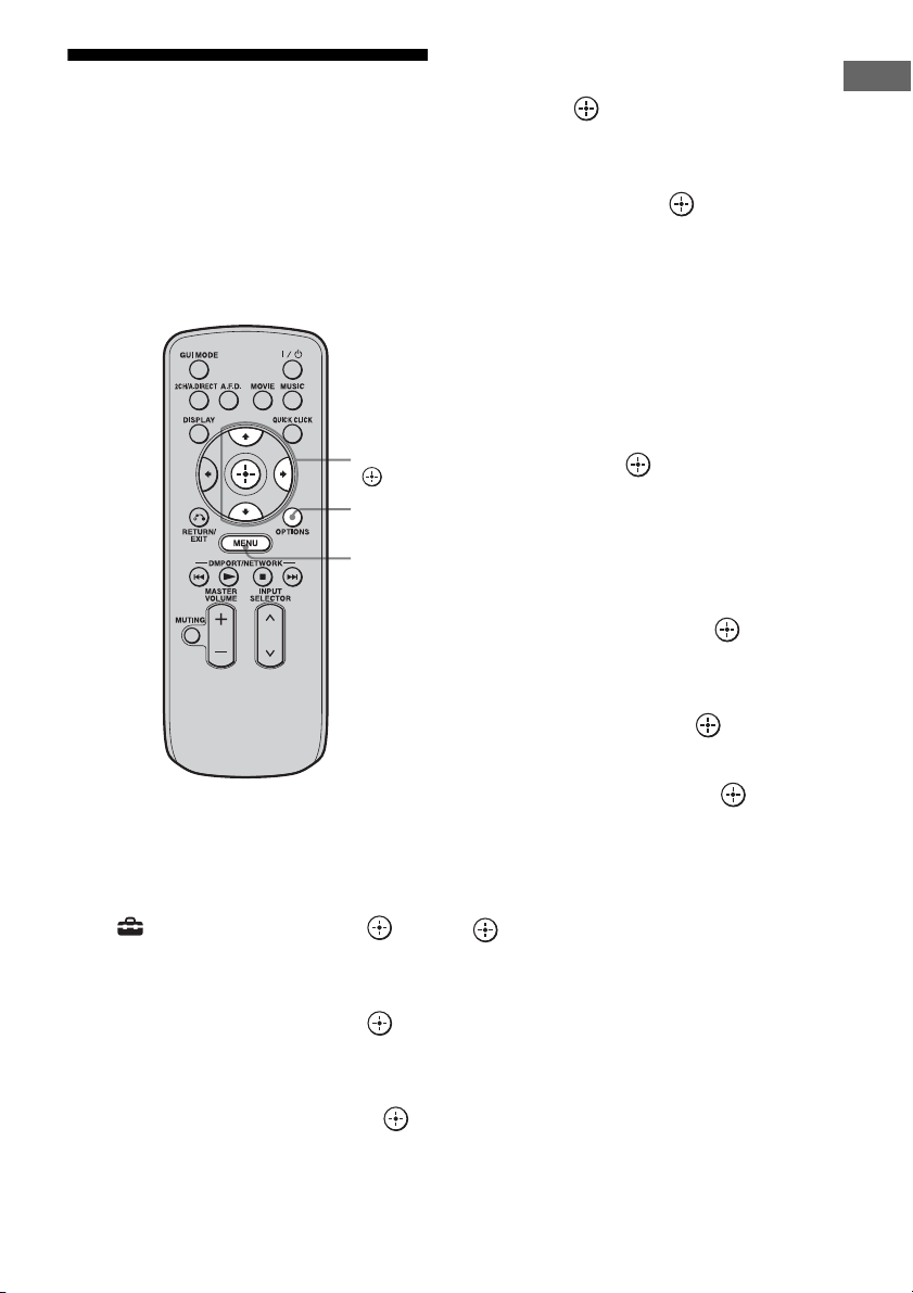
165
GB
Operating Each Component Using the On-screen Remote (Quick Click)
Performing several
commands in sequence
automatically with Quick
Click (Macro Play)
You can use the macro function easily with
Quick Click.
1 Press MENU.
The menu is displayed on the TV screen.
2 Press V/v repeatedly to select
“ Settings,” then press or
b.
3 Press V/v repeatedly to select
“Quick Click,” then press or
b.
4 Press V/v repeatedly to select
“Macro Setup,” then press .
5 Press V/v repeatedly to select
the macro number for which
you want to program the
sequence of operation(s), then
press .
6 Press V/v repeatedly to select
the step number you want to
set, then press .
7 Press V/v repeatedly to select
the component you want, then
press b.
8 Press V/v repeatedly to select
the key, then press b.
9 Press V/v repeatedly to select
the duration of time you want,
then press .
10Repeat steps 6 to 9 when you
want to program operations for
other components.
11Press V/v/b to select Step
Interval, then press .
12Press V/v repeatedly to select
the step interval time you want
to set, then press .
13Press V/v/b repeatedly to select
“Finish,” then press .
The settings process is complete.
To cancel programming
Press V/v/B/b to select “Cancel,” then press
.
V/v/b,
MENU
OPTIONS
166
GB
1 Press QUICK CLICK.
The on-screen remote is displayed on the
TV screen.
2 Press V/v/B/b to select MACRO
on on-screen remote.
The macro list appears on the TV screen.
3 Press V/v to select the macro
number you want to start.
The macro starts and executes the
commands in the order you assigned
them.
To input a macro name
1
Press MENU.
The menu is displayed on the TV screen.
2 Press V/v repeatedly to select
“ Settings,” then press or b.
3 Press V/v repeatedly to select “Quick
Click,” then press or b.
4 Press V/v repeatedly to select “Macro
Setup,” then press .
5 Press OPTIONS.
The option menu appears.
6 Press to select “Name Input.”
The soft keyboard appears on the TV
screen.
7 Press V/v/B/b and to select a
character one by one.
8 Press V/v/B/b to select “Finish,” then
press .
The name you entered is registered.
To cancel naming input
Press V/v/B/b to select “Cancel,” then press
.
To erase a programmed macro
1
Press MENU.
The menu is displayed on the TV screen.
2 Press V/v repeatedly to select
“ Settings,” then press or b.
3 Press V/v repeatedly to select “Quick
Click,” then press or b.
4 Press V/v repeatedly to select “Macro
Setup,” then press .
5 Press V/v repeatedly to select the
macro number you want, then press
.
6 Press V/v repeatedly to select the step
number you want, then press .
7 Press V/v repeatedly to select “–” as a
component name, the press .
8 Repeat steps 7 and 8 to clear the
stored macro.
9 Press V/v/b repeatedly to select
“Finish,” then press .
Settings stored as a macro are cleared.
Starting macro play
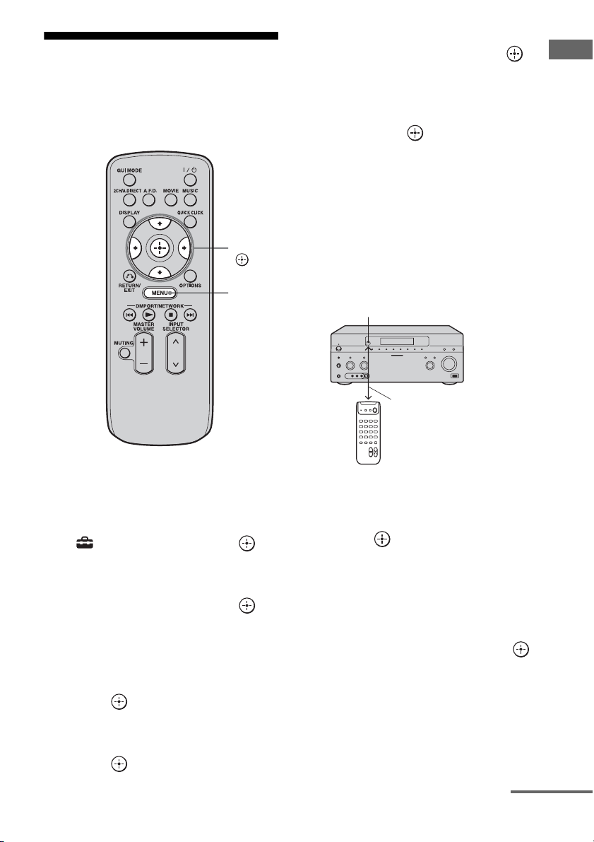
167
GB
Operating Each Component Using the On-screen Remote (Quick Click)
Setting remote control
codes that are not stored
in Quick Click
1
Press MENU.
The menu is displayed on the TV screen.
2 Press V/v repeatedly to select
“ Settings,” then press or
b.
3 Press V/v repeatedly to select
“Quick Click,” then press or
b.
4 Press V/v repeatedly to select
“Source Component,” or
“Common Component,” then
press .
5 Press V/v repeatedly to select
the component you want, then
press .
6 Press V/v repeatedly to select
“Learn Mode,” then press .
7 Press V/v repeatedly to select
the code number you want to
store as the new command,
then press .
8 Keep pressing the
corresponding button on the
remote of the component to be
programmed while pointing the
remote toward the receiver’s
remote sensor until
“Complete” is displayed on the
TV screen.
“Test” is selected automatically after few
seconds when the registration of a new
code is completed.
9 Press .
The operation test of the programmed
code is started.
Proceed to step 10 if you will not perform
the operation test.
10Press V/v/B/b repeatedly to
select “Finish,” then press .
Note
The display window is turned off while the receiver
is registering the new code.
V/v/B/b,
MENU
Remote sensor
About 5 cm - 10 cm (2" - 4")
continued
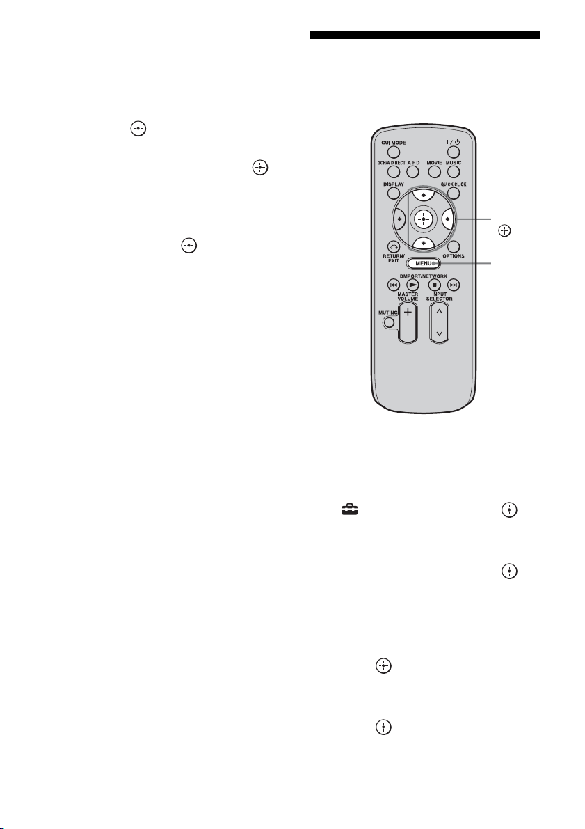
168
GB
To use a command that has
been learned
1
Press MENU.
The menu is displayed on the TV screen.
2 Press V/v repeatedly to select “Input,”
then press or b.
3 Press V/v repeatedly to select the
component you want, then press .
4 Press QUICK CLICK.
5 Press V/v/B/b to select the button on
the on-screen remote used to learn that
function, then press .
Resetting the remote
code for Quick Click
1
Press MENU.
The menu is displayed on the TV screen.
2 Press V/v repeatedly to select
“ Settings,” then press or
b.
3 Press V/v repeatedly to select
“Quick Click,” then press or
b.
4 Press V/v repeatedly to select
“Source Component,” or
“Common Component,” then
press .
5 Press V/v repeatedly to select
the component you want, then
press .
V/v/b,
MENU

169
GB
Operating Each Component Using the On-screen Remote (Quick Click)
6 Press V/v repeatedly to select
“Reset,” then press .
The confirming message appears on the
TV screen.
7 Press V/v repeatedly to select
“Yes,” then press .
All the contents of the selected input (e.g.,
all the programmed data) are cleared.
8 Repeat steps 5 to 7 to clear all
programmed data.
Note
The macro itself is not cleared. A default code will
be output when you have set a preset code or learned
code in the macro step.

170
GB
Operating each
component using the
multifunction remote
You can control Sony or non-Sony
components you are using with the
multifunction remote supplied with the
receiver.
The remote is initially set to control Sony
components.
When you change the settings of the remote
according to the components you are using,
you can control non-Sony and other Sony
components that the remote is initially unable
control (page 172).
1 Press the input button that
matches the connected
component that you want to
operate.
2 Press the appropriated buttons
to use the function listed in the
table below.
Note
You may not be able to operate some functions for
the components you are using.
Operating Each Component
Using the Multifunction Remote
Operating the components
connected to the receiver
171
GB
Operating Each Component Using the Multifunction Remote
Table of buttons used to control each component
*1 LD player only
*2 Deck B only
*3 DVD only
*4 Video CD only
*5 USA/Canadian model only
*6 European model only
Component
Button
TV VCR DVD
player,
DVD/VHS
combo
Blu-ray
Disc
Player
HDD
Recorder
PSX Video CD
player, LD
player
Digital
CATV
terminal
*
5
DSS
*
5
Digital
Satellite/
Terrestrial
receiver*
6
Tape
deck
A/B
DAT
deck
CD
player,
MD deck
DIGITAL
MEDIA
PORT
device
AV
?
/
1
zzz z zzz zz z zz
Numeric buttons
zzz z zzz zz z zzz z
TV INPUT, WIDE
z
-/--
zzz z zzz zz z z
ENT/MEM
zz z z z z z
*1
zz zz z
CLEAR
zz zz z z
TOOLS/OPTIONS
zzzzz zz
DISPLAY
zzz z zzz zz z
RETURN/EXIT
z z z zzz zz z z
V
/
v
/
B
/
b
, ,
MENU, HOME
zz z z z z z z z z
.
/
>
zzz z zzz z z
*2
zz z
B
·/·
b
zzzzz z z
m
/TUNING –,
M
/TUNING +
zzz z zzz z zzz z
DISC SKIP
z
*3
zz
*4
z
N
,
X
,
x
zzz z zzz z zzz z
MUTING,
MASTER VOL +/–,
TV VOL +/–
z
PRESET +/–,
TV CH +/–
zz z z z z
*1
zz z
BD/DVD TOP MENU,
BD/DVD MENU
zz z
F1, F2
zz
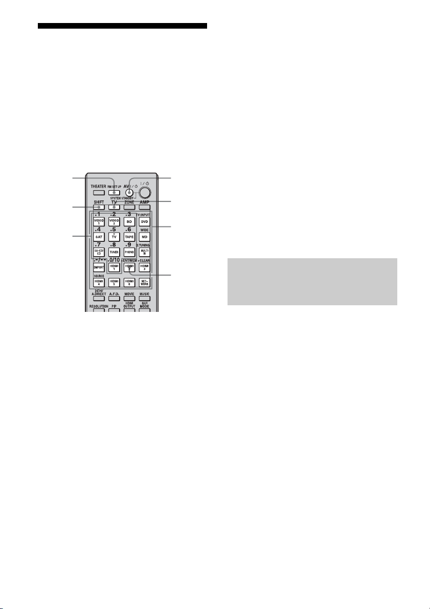
172
GB
Programming the remote
You can customize the remote to match the
components connected to your receiver. You
can even program the remote to control non-
Sony components and also Sony components
that the remote is normally unable to control.
The procedure below uses as an example a
case in which a VCR made by a company other
than Sony is connected to the VIDEO 2 IN
jacks on the receiver.
1 Press AV ?/1 while pressing RM
SET UP.
The RM SET UP button flashes.
2 While the RM SET UP button is
flashing, press the input button
(including the TV button) for the
component you want to control.
For example, if you are going to control a
VCR connected to VIDEO 2 IN jack,
press VIDEO 2.
RM SET UP and the input button light up.
If you press the button for a component of
which you cannot program the remote,
such as TUNER, PHONO, DMPORT or
SOURCE, etc., the RM SET UP button
keeps flashing.
3 Press the numeric buttons to
enter the numeric code (or one
of the codes if more than one
code exists) corresponding to
the component and the maker
of the component you want to
control.
The input button lights up.
Note
As a remote code value for the TV button, only
numbers in the 500’s are valid.
4 Press ENT/MEM.
Once the numeric code has been verified,
the RM SET UP button flashes twice and
the remote automatically exits the
programming mode. The input button
also turns off.
To cancel programming
Press RM SET UP during any step.
Use the numeric codes in the tables below to
control non-Sony components and also Sony
components that the remote is normally unable
to control. Since the remote signal that a
component accepts differs depending on the
model and year of the component, more than
one numeric code may be assigned to a
component. If you fail to program your remote
using one of the codes, try using other codes.
Notes
• The numeric codes are based on the latest
information available for each brand. There is a
chance, however, that your component will not
respond to some or all of the codes.
• All of the input buttons on this remote may not be
available when used with your particular
component.
Numeric
buttons
AV ?/1RM SET
UP
ENT/
MEM
SHIFT
Input
buttons
TV
The numeric codes
corresponding to the component
and the maker of the component

173
GB
Operating Each Component Using the Multifunction Remote
To control a CD player
To control a DAT deck
To control a tape deck
To control an MD deck
To control an HDD recorder
To control a Blu-ray Disc Player
To control a PSX
To control a DVD player
To control a DVD/VIDEO
COMBO (recorder)
To control a HDD/DVD COMBO
(recorder)
To control a TV
Maker Code(s)
SONY 101, 102, 103
DENON 104, 123
JVC 105, 106, 107
KENWOOD 108, 109, 110
MAGNAVOX 111, 116
MARANTZ 116
ONKYO 112, 113, 114
PANASONIC 115
PHILIPS 116
PIONEER 117
TECHNICS 115, 118, 119
YAMAHA 120, 121, 122
Maker Code(s)
SONY 203
PIONEER 219
Maker Code(s)
SONY 201, 202
DENON 204, 205
KENWOOD 206, 207, 208, 209
NAKAMICHI 210
PANASONIC 216
PHILIPS 211, 212
PIONEER 213, 214
TECHNICS 215, 216
YAMAHA 217, 218
Maker Code(s)
SONY 301
DENON 302
JVC 303
KENWOOD 304
Maker Code(s)
SONY 307, 308, 309
Maker Code(s)
SONY 310, 311, 312
Maker Code(s)
SONY 313, 314, 315
Maker Code(s)
SONY 401, 402, 403
BROKSONIC 424
DENON 405
HITACHI 416
JVC 415, 423
MITSUBISHI 419
ORITRON 417
PANASONIC 406, 408, 425
PHILIPS 407
PIONEER 409, 410
RCA 414
SAMSUNG 416, 422
TOSHIBA 404, 421
ZENITH 418, 420
Maker Code(s)
SONY 411
Maker Code(s)
SONY 401, 402, 403
Maker Code(s)
SONY 501
AIWA 501, 536, 539
AKAI 503
AOC 503
CENTURION 566
CORONADO 517
CURTIS-MATHES 503, 551, 566, 567
DAYTRON 517, 566
DAEWOO 504, 505, 506, 507, 515,
544
FISHER 508, 545
FUNAI 548
FUJITSU 528
continued

174
GB
To control an LD player
To control a video CD player
To control a VCR
* If an AIWA VCR does not work even though you
enter the code for AIWA, enter the code for Sony
instead.
To control a satellite tuner (box)
GOLDSTAR/LG 503, 512, 515, 517, 534,
544, 556, 568, 576
GRUNDIG 511, 533, 534
HITACHI 503, 513, 514, 515, 517,
519, 544, 557, 571
ITT/NOKIA 521, 522
J.C.PENNY 503, 510, 566
JVC 516, 552
KMC 517
MAGNVOX 503, 515, 517, 518, 544,
566
MARANTZ 527
MITSUBISHI/MGA 503, 519, 527, 544, 566,
568
NEC 503, 517, 520, 540, 544,
554, 566
NORDMENDE 530, 558
NOKIA 521, 522, 573, 575
PANASONIC 509, 524, 553, 559, 572
PHILIPS 515, 518, 557, 570, 571
PHILCO 503, 504, 514, 517, 518
PIONEER 509, 525, 526, 540, 551,
555
PORTLAND 503
QUASAR 509, 535
RADIO SHACK 503, 510, 527, 565, 567
RCA/PROSCAN 503, 510, 523, 529, 544
SAMSUNG 503, 515, 517, 531, 532,
534, 544, 556, 557, 562,
563, 566, 569
SAMPO 566
SABA 530, 537, 547, 549, 558
SANYO 508, 545, 546, 560, 567
SCOTT 503, 566
SEARS 503, 508, 510, 517, 518,
551
SHARP 517, 535, 550, 561, 565
SYLVANIA 503, 518, 566
THOMSON 530, 537, 547, 549
TOSHIBA 535, 539, 540, 541, 551
TELEFUNKEN 530, 537, 538, 547, 549,
558
TEKNIKA 517, 518, 567
WARDS 503, 517, 566
YORK 566
ZENITH 542, 543, 567
GE 503, 509, 510, 544
LOEWE 515, 534, 556
Maker Code(s)
Maker Code(s)
SONY 601, 602, 603
PIONEER 606
Maker Code(s)
SONY 605
Maker Code(s)
SONY 701, 702, 703, 704, 705,
706
AIWA* 710, 750, 757, 758
AKAI 707, 708, 709, 759
BLAUPUNKT 740
EMERSON 711, 712, 713, 714, 715,
716, 750
FISHER 717, 718, 719, 720
GENERAL ELECTRIC
(GE)
721, 722, 730
GOLDSTAR/LG 723, 753
GRUNDIG 724
HITACHI 722, 725, 729, 741
ITT/NOKIA 717
JVC 726, 727, 728, 736
MAGNAVOX 730, 731, 738
MITSUBISHI/MGA 732, 733, 734, 735
NEC 736
PANASONIC 729, 730, 737, 738, 739,
740
PHILIPS 729, 730, 731
PIONEER 729
RCA/PROSCAN 722, 729, 730, 731, 741,
747
SAMSUNG 742, 743, 744, 745
SANYO 717, 720, 746
SHARP 748, 749
TELEFUNKEN 751, 752
TOSHIBA 747, 756
ZENITH 754
Maker Code(s)
SONY 801, 802, 803, 804, 824,
825, 865

175
GB
Operating Each Component Using the Multifunction Remote
To control a cable box
Performing several
commands in sequence
automatically
(Macro Play)
The Macro Play function lets you link several
commands in a sequential order as a single
command.
The remote provides 2 macro lists (MACRO 1
and MACRO 2). You can specify up to 20
commands for each macro list.
Note
When setting up Macro Play, replace the batteries
with new ones.
AMSTRAD 845, 846
BskyB 862
GENERAL
ELECTRIC(GE)
866
GRUNDIG 859, 860
HUMAX 846, 847
THOMSON 857, 861, 864, 876
PACE 848, 849, 850, 852, 862,
863, 864
PANASONIC 818, 855
PHILIPS 856, 857, 858, 859, 860,
864, 874
NOKIA 851, 853, 854, 864
RCA/PROSCAN 866, 871
HITACHI/BITA 868
HUGHES 867
JVC/Echostar/Dish
Network
873
MITSUBISHI 872
SAMSUNG 875
TOSHIBA 869, 870
Maker Code(s)
SONY 821, 822, 823
HAMLIN/REGAL 836, 837, 838, 839, 840
JERROLD/G.I./
MOTOROLA
806, 807, 808, 809, 810,
811, 812, 813, 814, 819
JERROLD 830, 831
OAK 841, 842, 843
PANASONIC 816, 826, 832, 833, 834,
835
PHILIPS 830, 831
PIONEER 828, 829
RCA 805
SCIENTIFIC ATLANTA 815, 816, 817
TOCOM/PHILIPS 830, 831
ZENITH 826, 827
Maker Code(s)
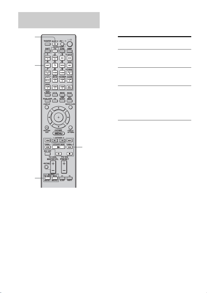
176
GB
1 Press MACRO 1 or MACRO 2 for
more than 1 second while
pressing RM SET UP.
The RM SET UP button flashes and one
of the input buttons lights up (as the initial
setting, the VIDEO1 button lights).
2 Press the input button for the
component for which you want
to program the sequence of
operation(s).
3 Press the buttons you want to
program in the same sequence
as you want the operation(s) to
be performed.
The input button selected in step 2 flashes
twice, then lights up again.
4 Repeat steps 2 and 3 when you
want to program operations for
other components.
5 Press RM SET UP to finish the
programming process.
Tip
If the RM SET UP button flashes five times in
step 1, and the macro programming process
does not start, replace the batteries with new
ones.
To cancel programming
Press RM SET UP. Also, not pressing any
button for 60 seconds cancels the settings.
The previous command remains valid.
Program the sequence of the
operation
RM SET
UP
N, x, X,
M, m,
., >
Input
buttons
MACRO 1
MACRO 2
Press Operations to be
programmed
N, x, X,
M, m,
., >
Performs the operation
of the button.
The input
button for more
than 1 second
Switches inputs.
MACRO 1 or
MACRO 2
Make a one second
interval. When you want
to make a longer
interval, press MACRO
1 or MACRO 2
repeatedly.
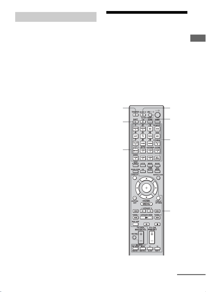
177
GB
Operating Each Component Using the Multifunction Remote
1 Press AMP.
The AMP button lights up, and then turns
off.
2 Press MACRO 1 or MACRO 2 to
start the macro.
The macro starts and execute the
commands in the order you assigned
them. While the commands are being
sent, the AMP button flashes and the RM
SET UP button lights up. When the
commands have been sent, the RM SET
UP and AMP buttons turn off.
To erase a programmed macro
1
Press MACRO 1 or MACRO 2 for more
than 1 second while pressing RM SET
UP to clear the stored macro.
The RM SET UP button flashes.
2 Press RM SET UP.
Settings stored as macro are cleared.
Setting remote
commander codes that
are not stored in the
remote
Even if a remote commander code is not one of
the presets stored in the remote, it is possible
for the remote to learn the code using the
learning function.
Note
When setting up the receiver to learn the remote
command modes, replace the batteries with new
ones.
* To store a new command on one of those buttons,
press SHIFT beforehand.
Starting macro play
THEATER
Buttons
used to
learn
code*
SHIFT
RM SET
UP
Input
buttons
TV
Buttons
used to
learn
code
continued

178
GB
1 Press THEATER while pressing
RM SET UP.
The RM SET UP button lights up.
2 Press the input button
(including the TV button) for the
component you want to operate
with the new command.
The input button flashes. (The RM SET
UP button remains lit.)
3 Press the button on which you
want to store the new
command. For the buttons with
an asterisk in the illustration
above, press SHIFT, then press
the button.
The input button you selected in step 2
lights up. (The RM SET UP button
remains lit.)
4 Point the remote code receiver
section of the remote toward
the transmitter on the remote
commander to be learned from.
5 Press the button on the remote
commander to be learned from
to transmit the remote code.
While the remote of the receiver is
receiving the signal, the input button
selected in step 2 turns off.
The RM SET UP button flashes twice,
then the learning process is completed.
When the learning process fails, the RM
SET UP button flashes five times. Try to
perform process again from step 2.
6 Press RM SET UP to finish the
Learning function process.
Tips
• When the memory capacity for storing remote
commander codes reaches a certain limit, the RM
SET UP button flashes 10 times, and then the
learning process ends.
• If the RM SET UP button flashes five times in step
1, and the learning process does not start, replace
the batteries with new ones.
To cancel learning
Press RM SET UP. Also, not pressing any
button for 60 seconds cancels the settings.
When selecting a learned input,
press the button used to learn that
function.
To erase the learned code
1
Press THEATER while pressing RM
SET UP.
2 Press the input button for which you
want to clear the setting.
The input button flashes. (The RM SET UP
button remains lit.)
3 Press ?/1 for more than 1 second.
The input button flashes twice, repeatedly.
4 Press SHIFT, then press numeric
buttons to clear the stored setting.
The RM SET UP button flashes twice, then
the clearing process is completed.
When the clearing process fails, the RM
SET UP button flashes five times. Try to
perform process again from step 2.
About 5 cm - 10 cm (2" - 4")
Using a command that has been
learned
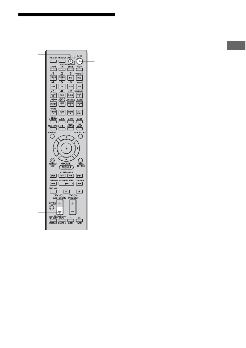
179
GB
Operating Each Component Using the Multifunction Remote
Clearing all the contents
of the remote’s memory
1
Press and hold MASTER VOL –
first, then press ?/1, then press
AV ?/1.
The RM SET UP button flashes three
times.
2 Release all buttons.
All the contents of the remote’s memory
(e.g., all the programmed data) are
cleared.
MASTER
VOL
?/1
AV ?/1

180
GB
Glossary
x Broadband
General name for communication lines that
use a broad frequency bandwidth for sending
and receiving large amounts of video or audio
data at high speed. Currently, ADSL, CATV,
FTTH and other systems are identified as
broadband.
x Broadband router
For Internet connections through ADSL or a
cable TV line, devices called ADSL modems
or cable modems are used. However, for
Internet access from multiple terminals
connected at once, a broadband router is used.
x Component video
A format for transmitting video signal
information consisting of three separate
signals: luminance Y, chrominance Pb, and
chrominance Pr. High quality pictures, such as
DVD video or HDTV pictures, are transmitted
more faithfully. The three jacks are color-
coded green, blue, and red.
x Composite video
A standard format for transmitting video
signal information. The luminance signal Y
and chrominance signal C are combined and
transmitted together.
x Crossover frequency
The frequency at which two speaker’s
frequencies intersect.
x Deep Color
Video signals for which the color depth of
signals passing through an HDMI jack have
been raised.
The number of colors that could be expressed
by 1 pixel was 24 bits (16,777,216 colors) with
the current HDMI jack. However, the number
of colors which can be expressed by 1 pixel
will be 36, etc., bits when the receiver
corresponds to Deep Color.
Since the gradation of the depth of a color can
be expressed more finely with more bits,
continuous color changes can be more
smoothly expressed.
x DHCP
Abbreviation of Dynamic Host Configuration
Protocol.
A set of rules to automatically assign settings
necessary for network communication.
x Digital Concert Hall
“Digital Concert Hall” delivers richer sound
for 2ch stereo sources such as CDs, etc. With
the use of 5.1ch or 7.1ch speakers and virtual
speaker technology, stereoscopic
reverberation and reflected sound are
reproduced, and music software can be
enjoyed with richer sound and presence. The
sound field in a concert hall is recreated by a
geometrical analysis of the concert hall and
precise modeling of reflected and reverberant
sounds based on actual measured data. Tonal
qualities such as sound strength and frequency
response are taken into account and calculated
on the DSP (Digital Signal Processor) to bring
reverberation in. Sound is enjoyed with natural
and comfortable resonance, as if listening to
music in a concert hall.
Additional Information

181
GB
Additional Information
x Digital Legato Linear (D.L.L.)
This is Sony proprietary technology that
allows low quality digital audio signals to be
played back with high quality sound. Old
recording or compressed audio often have
noise on the waveform and out-of-frequency
distortion, as well as harmonic distortion, in
the audio frequency is generated. Therefore
beat interference and ringing occur, and such
phenomena degrade the sound quality. The
D.L.L. feature eliminates these problems, and
gives you rich sound for music and movies.
x DLNA
Abbreviation of Digital Living Network
Alliance.
An association that formulates audio/photo/
video distribution among PCs and other digital
devices in a home network environment, or the
format itself.
DLNA certified devices are interoperable with
each other, thus making them easy to
communicate on the network.
x DNS
Abbreviation of Domain Name System. A
server that translates domain names to IP
addresses, or IP addresses to domain names. A
DNS is identified by an IP address. Also called
a “DNS server.”
x Dolby Digital
Digital audio encoding/decoding technology
developed by Dolby Laboratories, Inc. It
consists of front (left/right), center, surround
(left/right) and subwoofer channels. It is a
designated audio standard for DVD-video and
also known as 5.1 channels surround.
x Dolby Digital Plus
Dolby Digital Plus provides the flexibility and
efficiency to deliver more channels of
compelling surround sound for high-definition
video media. Its superior coding efficiencies
enable up to 7.1ch of high-quality
multichannel audio without negatively
impacting bit budgets allocated for video
performance or additional feature sets.
x Dolby Digital Surround EX
Acoustic technology developed by Dolby
Laboratories, Inc. Surround back information
is matrixed into regular left and right surround
channels so that the sound can be reproduced
in 6.1 channels. Active scenes, especially, are
recreated with a more dynamic and realistic
sound field.
x Dolby Pro Logic II
This technology converts 2 channels stereo
recorded audio into 5.1 channels for playback.
Old movies encoded in the traditional stereo
format can be enhanced with 5.1 channels
surround sound.
x Dolby Pro Logic IIx
Technology for 7.1 channels (or 6.1 channels)
playback. Along with audio encoded in Dolby
Digital Surround EX, 5.1 channels Dolby
Digital encoded audio can be reproduced in
7.1 channels (or 6.1 channels). Furthermore,
existing stereo recorded content can also be
reproduced in 7.1 channels (or 6.1 channels).
x Dolby Surround (Dolby Pro
Logic)
Audio processing technology developed by
Dolby Laboratories, Inc. Center and mono
surround information is matrixed into two
stereo channels. When reproduced, audio is
decoded and output in 4 channels surround
sound. This is the most common audio
processing method for DVD-video.
x Dolby TrueHD
Dolby TrueHD is Dolby’s lossless audio
technology developed for high-definition
optical discs. Dolby TrueHD audio is bit-for-
bit identical to the original studio masters and
provides supreme-quality audio up to 8ch at
96 kHz/24 bit and up to 6ch at 192 kHz/24 bit.
Together with high-definition video, it offers
an unprecedented home theater experience.
continued

182
GB
x DSD
Audio format used for a Super Audio CD.
DSD converts analog signals to digital and
records them directly, without adding any
processing, so that no information is omitted.
Recording and playback of high fidelity,
quality sound is achieved.
x DTS 96/24
A high sound quality digital signal format. It
records audio at a sampling frequency and bit
rate of 96 kHz/24 bit which is the highest
possible for DVD-video. The number of
playback channels varies depending on the
software.
x DTS Digital Surround
Digital audio encoding/decoding technology
for theaters developed by DTS, Inc. It
compresses audio less than Dolby Digital,
delivering a higher quality sound
reproduction.
x DTS Neo:6
This technology converts 2 channels stereo
recorded audio for 7 channels playback. There
are two modes to select according to the
playback source or your preference, CINEMA
for movies, and MUSIC for stereo sources
such as music.
x DTS-ES
Format for 6.1 channels playback with
surround back information. There are two
modes, “Discrete 6.1” which records all
channels independently, and “Matrix 6.1”
which matrixes surround back channel into
surround left and surround right channels. It is
ideal for playback of motion picture
soundtracks.
x DTS-HD
Audio format which extends the conventional
DTS Digital Surround format.
This format consists of a core and an
extension, and the core part has DTS Digital
Surround compatibility. There are two kinds of
DTS-HD, DTS-HD High Resolution Audio
and DTS-HD Master Audio. DTS-HD High
Resolution Audio has a maximum
transmission rate of 6 Mbps, with lossy
compression (Lossy), and DTS-HD High
Resolution Audio corresponds to a maximum
sampling frequency of 96 kHz, and a
maximum of 7.1 ch. DTS-HD Master Audio
has a the maximum transmission rate of
24.5 Mbps, and uses lossless compression
(Lossless), and DTS-HD Master Audio
corresponds to a maximum sampling
frequency of 192 kHz, and a maximum of 7.1
ch.
x Gateway
An IP address of a device such as a computer
or a router, etc., which is required when the
receiver accesses the Internet or an external
network.
x H.A.T.S. (High quality digital
Audio Transmission System) for
HDMI
H.A.T.S. for HDMI is a flow control playback
system for HDMI transmission.
A master clock, important for audio quality, is
provided by a crystal transmitter beside the
DA converter of the receiver, and this master
clock controls the playback speed of the
components connected to the receiver using
the HDMI CEC (Consumer Electronics
Control) for HDMI (High-Definition
Multimedia Interface) to match the playback
rate. It gives you high quality sound with
exceptional clarity, because, there is nearly no
transmission jitter when transmitting the
clock.

183
GB
Additional Information
x HD Digital Cinema Sound (HD-
D.C.S.)
HD Digital Cinema Sound (HD-D.C.S.) is
Sony’s new innovative home theater
technology using the latest acoustic and digital
signal processing technologies. It is based on
precise response measurement data of a
mastering studio.
With HD-D.C.S., you are able to enjoy Blu-ray
and DVD movies at home with not only the
high quality of sound, but also the best sound
ambience, just as the movie’s sound engineer
intended in the mastering process.
x HDMI (High-Definition
Multimedia Interface)
HDMI (High-Definition Multimedia
Interface) is an interface that supports both
video and audio on a single digital connection,
allowing you to enjoy high quality digital
picture and sound. The HDMI specification
supports HDCP (High-bandwidth Digital
Contents Protection), a copy protection
technology that incorporates coding
technology for digital video signals.
x High Bitrate Audio
It refers to the audio formats of the
compression method (DTS-HD Master Audio,
Dolby TrueHD, etc.) which is a high bitrate
format recorded mainly on Blu-ray Disc etc.
x Interlace
A scanning method which completes a picture
by displaying half of the lines on a tube surface
of a TV or monitor each 1/60 second. First, all
the odd-numbered lines are drawn, leaving
spaces between each line, then all the even-
numbered lines are drawn to fill the spaces.
“i” of “480i” stands for “Interlace.”
x Internet
A communication network linking computers
around the world. The Internet supports many
services, including email and search engines.
x L.F.E. (Low Frequency Effects)
Sound effects of low frequencies which are
output from a subwoofer in Dolby Digital or
DTS, etc. By adding a deep bass with a
frequency between 20 to 120 Hz, audio
becomes more powerful.
x LAN
Abbreviation of Local Area Network.
LAN is a general name for networks set up for
communication among devices including
computers, printers, and fax machines in
relatively small areas such as offices or
buildings.
x Neural-THX
Neural Surround™, THX
®
Technologies has
been chosen as the official surround sound
broadcast format for XM Satellite Radio’s
“XM HD Surround” and other leading FM/HD
radio stations in the USA and worldwide.
Neural Surround, THX Technologies delivers
the rich envelopment and discrete image detail
of surround sound in a format 100%
compatible with stereo.
x PCM (Pulse Code Modulation)
A method of converting analog audio to digital
audio for easy enjoyment of digital sound.
x Progressive
A scanning method that draws all scanning
lines sequentially, as opposed to interlaced
scanning where all the odd and then all the
even lines are drawn.
“p” of “480p” stands for “Progressive.”
x Router
Device that relays data flow from network to
network. Routers are usually installed between
the Internet and the home network. Some
routers are capable of connecting multiple
devices to the Internet.
x Server
A device which provides content such as
music, photos, or videos to clients on your
home network.
continued

184
GB
x Subnet mask
Part of an IP address that identifies the subnet,
a smaller group on the network.
x x.v.Color
“x.v.Color” enables the more faithful
reproduction of various colors such as the
brilliant colors of flowers and the turquoise
blue of the southern ocean.
Precautions
On safety
Should any solid object or liquid fall into the
cabinet, unplug the receiver and have it
checked by qualified personnel before
operating it any further.
On power sources
• Before operating the receiver, check that the
operating voltage is identical with your local
power supply.
The operating voltage is indicated on the
nameplate on the back of the receiver.
• The unit is not disconnected from the AC
power source (mains) as long as it is
connected to the wall outlet, even if the unit
itself has been turned off.
• If you are not going to use the receiver for a
long time, be sure to disconnect the receiver
from the wall outlet. To disconnect the AC
power cord (mains lead), grasp the plug
itself; never pull the cord.
• One blade of the plug is wider than the other
for the purpose of safety and will fit into the
wall outlet only one way. If you are unable to
insert the plug fully into the outlet, contact
your dealer.
• AC power cord (mains lead) must be
changed only at a qualified service shop.
On heat buildup
Although the receiver heats up during
operation, this is not a malfunction. If you
continuously use this receiver at a large
volume, the cabinet temperature of the top,
side and bottom rises considerably. To avoid
burning yourself, do not touch the cabinet.
On placement
• Place the receiver in a location with adequate
ventilation to prevent heat buildup and
prolong the life of the receiver.

185
GB
Additional Information
• Do not place the receiver near heat sources,
or in a place subject to direct sunlight,
excessive dust, or mechanical shock.
• Do not place anything on top of the cabinet
that might block the ventilation holes and
cause malfunctions.
• Do not place the receiver near equipment
such as a television, VCR, or tape deck. (If
the receiver is being used in combination
with a television, VCR, or tape deck, and is
placed too close to that equipment, noise
may result, and picture quality may suffer.
This is especially likely when using an
indoor antenna (aerial). Therefore, we
recommend using an outdoor antenna
(aerial).)
On operation
Before connecting other components, be sure
to turn off and unplug the receiver.
On cleaning
Clean the cabinet, panel, and controls with a
soft cloth slightly moistened with a mild
detergent solution. Do not use any type of
abrasive pad, scouring powder, or solvent,
such as alcohol or benzine.
If you have any questions or problems
concerning your receiver, please consult your
nearest Sony dealer.
Troubleshooting
If you experience any of the following
difficulties while using the receiver, use this
troubleshooting guide to help you remedy the
problem. Should any problem persist, consult
your nearest Sony dealer.
There is no sound, no matter which
component is selected, or only a very
low-level sound is heard.
• Check that the speakers and components
are connected securely.
• Check that all speaker cords are connected
correctly.
• Check that both the receiver and all
components are turned on.
• Check that MASTER VOLUME control is
not set at –∞ dB. Try to set it at about –40
dB.
• Check that SPEAKERS (OFF/A/B/A+B)
is not set to OFF (page 50).
• Press MUTING on the remote to cancel
the muting function.
• Check that you have selected the correct
component with INPUT SELECTOR.
• Check that headphones are not connected.
• When only a very low-level sound is
heard, check to see if Night Mode is
activated (page 122).
• The protective device on the receiver has
been activated. Turn off the receiver,
eliminate the short-circuit problem, and
turn on the power again.
There is no sound from a specific
component.
• Check that the component is connected
correctly to the audio input jacks for that
component.
• Check that the cord(s) used for the
connection is (are) fully inserted into the
jacks on both the receiver and the
component.
Audio
continued

186
GB
There is no sound from one of the front
speakers.
• Connect a pair of headphones to the
PHONES jack to verify that sound is
output from the headphones. If only one
channel is output from the headphones, the
component may not be connected to the
receiver correctly. Check that all the cords
are fully inserted into the jacks on both the
receiver and the component. If both
channels are output from the headphones,
the front speaker may not be connected to
the receiver correctly. Check the
connection of the front speaker which is
not outputting any sound.
• Make sure you have connected both the L
or R jack to an analog component and not
just to either the L or R jack. Use a
monaural-stereo cable (not supplied).
However, there will be no sound from the
center speaker when a sound field (Pro
Logic, etc.) is selected. When the center
speaker is not connected, sound is output
only from the front left/right speakers.
There is no sound from analog 2
channel sources.
• Check to make sure the selected audio
(digital) input jack is not assigned to other
inputs in “Input Assign” in the Input menu
(page 119).
There is no sound from digital sources
(from COAXIAL or OPTICAL input jack).
• Check that the INPUT MODE is not set to
“Analog.”
• Check that the “2ch Analog Direct” is not
being used.
• Check to make sure the selected audio
(digital) input jack is not assigned to other
inputs in “Input Assign” in the Input menu
(page 119).
The source sound input from the HDMI
IN jack is not output from an amplifier
or the TV speaker connected to the
receiver.
• Check that the component is connected
correctly to the HDMI IN jack for that
component.
• Depending on the playback component,
component may need to be set up. Refer to
the operating instructions supplied with
the each component.
• Be sure to use a connecting cable for the
HDMI jack corresponding to high speed
(an HDMI version1.3a, category 2 cable)
when you view images or listen to sound
during a 1080p or Deep Color
transmission.
The left and right sounds are
unbalanced or reversed.
• Check that the speakers and components
are connected correctly and securely.
• Adjust the balance parameters using the
Auto Calibration settings menu.
There is severe hum or noise.
• Check that the speakers and components
are connected securely.
• Check that the connecting cords are away
from a transformer or motor, and at least
3 meters (10 feet) away from a TV set or
fluorescent light.
• Move your TV away from the audio
components.
• Make sure you have grounded the U
SIGNAL GND terminal (only when a
turntable is connected).
• The plugs and jacks are dirty. Wipe them
with a cloth slightly moistened with
alcohol.

187
GB
Additional Information
There is no sound, or only a very low-
level sound is heard from the center/
surround/surround back speakers.
• Check that the speaker settings are
appropriate using the Auto Calibration
settings menu or “Speaker Pattern” in the
Speaker settings menu. And then check
that sound is output from each speaker
correctly, using “Test Tone” in the Speaker
settings menu.
• Select the “HD-D.C.S.” sound field
(page 88).
• Adjust the speaker level (page 131).
• Make sure the center/surround speaker (s)
is (are) set to either “SMALL” or
“LARGE.”
There is no sound from the surround
back speakers.
• Some discs have no Dolby Digital
Surround EX flag even though the
packages have Dolby Digital Surround EX
logos.
There is no sound from the subwoofer.
• Check that the subwoofer is connected
correctly and securely.
• Make sure you have turned on your
speaker.
• When all speakers are set to “LARGE”
and “Neo:6 Cinema,” or “Neo:6 Music” is
selected, there is no sound from the
subwoofer.
The surround effect cannot be
obtained.
• Make sure the sound field function is on
(press MOVIE or MUSIC).
• Sound fields do not work when DTS-HD
signals with a sampling frequency of
88.2 kHz and higher are being received.
• Sound fields do not work when Dolby
TrueHD signals with a sampling
frequency of 176.4 kHz and higher are
being received.
Dolby Digital or DTS multi-channel
sound is not reproduced.
• Check that the DVD, etc. you are playing
is recorded in Dolby Digital or DTS
format.
• When connecting the DVD player, etc., to
the digital input jacks of this receiver,
make sure the setting for the digital audio
output of the connected component is
available.
Recording cannot be carried out.
• Check that the components are connected
correctly (page 27).
• Select the source component (page 62).
The MULTI CHANNEL DECODING lamp
does not light up in blue.
• Check that the playback component is
connected on a digital jack and the input is
selected properly on this receiver.
• Check whether the input source of the
software being played back corresponds to
the multi-channel format.
• Check whether the setup on the playback
component is set to multi-channel sound.
• Check to make sure the selected audio
(digital) input jack is not assigned to other
inputs in “Input Assign” in the Input menu
(page 119).
There is no sound from the component
connected to the DIGITAL MEDIA PORT
adapter.
• Adjust the volume of this receiver.
• The DIGITAL MEDIA PORT adapter
and/or component is not connected
correctly. Turn off the receiver, then
reconnect the DIGITAL MEDIA PORT
adapter and/or component.
• Check the DIGITAL MEDIA PORT
adapter and/or component device to make
sure it supports this receiver.

188
GB
There is no picture or an unclear
picture appears on the TV screen or
monitor.
• Select the appropriate input on the receiver
(page 62).
• Set your TV to the appropriate input mode.
• Move your TV away from the audio
components.
• Assign the component video input
correctly.
• The input signal should be same as input
when you are up-converting an input
signal with this receiver (page 40).
The image of the COMPONENT VIDEO
OUT is corrupted.
• Video input signals other than 480p
component are not received when signals
are output from the VIDEO jack. Input
480i component video signals.
• When component input signals other than
480p are output, use the COMPONENT
VIDEO OUT jack and set “Resolution” to
“DIRECT.”
Images from the component connected
to the HDMI jack are not output to the
TV, are distorted, or are interrupted.
• The output of the HDMI video signals of
the receiver may be set to “OFF.” In this
case, select “HDMI A” or “HDMI B”
using the HDMI OUTPUT button
(page 116).
• If the compatible video format differs
between the monitors connected to the
HDMI OUT A jack and the HDMI OUT B
jack of the receiver, “HDMI A + B” may
not work.
• Depending on the playback component
you connect, “HDMI A + B” may not
work.
• Make sure that cables are correctly and
securely connected to components.
• Depending on the playback component,
component may need to be set up. Refer to
the operating instructions supplied with
the each component.
• Be sure to use a connecting cable for the
HDMI jack corresponding to high speed
(an HDMI version1.3a, category 2 cable)
when you view images or listen to sound
during a 1080p or Deep Color
transmission.
• Images from the component connected to
the HDMI jack may be distorted. In this
case, set “Video Direct” to “ON” in the
HDMI settings menu.
• Images or sound from the component
connected to the HDMI jack may be
interrupted when video signals are
switched. In this case, set “Video Direct”
to “ON” in the HDMI settings menu.
Recording cannot be carried out.
• Check that the components are connected
correctly (page 32).
• Select the source component (page 62).
The GUI does not appear on the TV
screen.
• “GUI MODE” may have been turned off.
Press GUI MODE to turn “GUI MODE”
on.
• Check the TV is connected correctly.
Images appear later than the
associated sound is played when the
HDMI input is selected.
• Depending on the component connected to
the HDMI jack, or the source played back,
images may appear later than the
associated sound. In this case, set “Video
Direct” to “ON” in the HDMI settings
menu.
Video
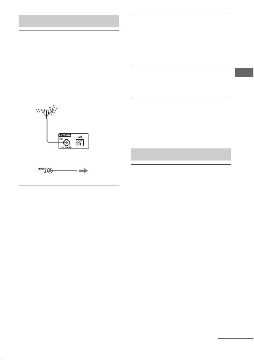
189
GB
Additional Information
The FM reception is poor.
• Use a 75-ohm coaxial cable (not supplied)
to connect the receiver to an outdoor FM
antenna (aerial) as shown on page 189. If
you connect the receiver to an outdoor
antenna (aerial), ground it against
lightning. To prevent a gas explosion, do
not connect the ground (earth) wire to a
gas pipe.
Radio stations cannot be tuned in.
• Check that the antennas (aerials) are
connected securely. Adjust the antennas
(aerials) and connect an external antenna
(aerial), if necessary.
• Keep the satellite radio antenna, away
from the speaker cords and the power cord
to avoid picking up noise.
• The signal strength of the stations is too
weak (when tuning in with automatic
tuning). Use direct tuning.
• Make sure you set the tuning interval
correctly (when tuning in AM stations
with direct tuning).
• No stations have been preset or the preset
stations have been cleared (when tuning by
scanning preset stations). Preset the
stations (page 71).
• Press DISPLAY so that the frequency
appears on the display.
The system cannot receive satellite
channels at all.
• The receiving condition is not good. Move
the antenna to the place where the
condition is good.
• Check that you subscribed to the desired
satellite radio service (see page 73).
RDS does not work.
• Make sure that you are tuned to an FM
RDS station.
• Select a stronger FM station.
The RDS information that you want
does not appear.
• Contact the radio station and find out
whether or not they actually provide the
service in question. If so, the service may
be temporarily out of order.
The Control for HDMI function does not
work.
• Check the HDMI connection (page 33).
• Make sure “Control for HDMI” is set to
“ON” in HDMI settings menu.
• Make sure the connected component is
compatible with the Control for HDMI
function.
• Check the Control for HDMI settings on
the connected component. Refer to the
operating instructions of the connected
component.
• If you change the HDMI connection,
connect/disconnect the AC power cord, or
there is a power failure, repeat the
procedures of “Preparing for the
“BRAVIA” Sync” (page 112).
• If you select “HDMI A” or “HDMI
A + B,” after you have selected “HDMI B”
or “OFF,” the Control for HDMI function
may not work properly for a while. This is
because the component connected to the
HDMI A jack must re-recognize the
receiver that is equipped with the Control
for HDMI function. If the Control for
Tuner
Receiver
To ground
Ground (earth)
wire (not supplied)
Outdoor FM antenna (aerial)
Control for HDMI
continued

190
GB
HDMI function does not work properly for
a long time, perform the steps given in
“Preparing for the “BRAVIA” Sync”
(page 112).
• When you select “HDMI B” or “OFF,” the
Control for HDMI function does not work
properly.
No sound is output from the receiver
and TV speaker while using the System
Audio Control function.
• Make sure the TV is compatible with the
System Audio Control function.
• If the TV does not have System Audio
Control function, set the “Audio Out”
settings in HDMI settings menu to
– “TV+AMP” if you want to listen to the
sound from the TV speaker and
receiver.
– “AMP” if you want to listen to the
sound from the receiver.
• When you connect the receiver to a video
component (projector, etc.), sound may
not be output from the receiver. In this
case, select “AMP.”
• You cannot listen to the sound of a
component connected to the receiver while
a TV is selected as the input on the
receiver.
– Change the input of the receiver to
HDMI when you want to watch a
program on a component connected to
the receiver.
– Change the TV channel when you want
to watch a TV broadcast.
– Select the component or input you want
to watch when you watch a program on
the component connected to the TV.
Refer to the operating instructions of the
TV on this operation.
• When using the Control for HDMI
function, you cannot control the connected
component using TV’s remote.
– Depending on the connected component
and TV, you may need to set up the
component and TV. Refer to the
operation instructions supplied with
each component and TV.
– Change the input of the receiver to the
HDMI input connected to the
component.
The remote does not function.
• Point the remote at the remote sensor on
the receiver.
• Remove any obstacles in the path between
the remote and the receiver.
• Replace all the batteries in the remote with
new ones, if they are weak.
• Make sure that the command modes of the
receiver and the remote are the same. If the
command mode of the receiver and the
remote are different, you cannot operate
the receiver with the remote (page 124).
• Make sure you select the correct input on
the remote.
• When you operate a programmed non-
Sony component, the remote may not
function properly depending on the model
and the maker of the component.
Cannot find the server.
• Check the following:
– Is the router is turned on?
– If there is another device between this
device and the router, check that device
is turned on.
– Are all of the cables are connected
correctly and securely?
– Is the settings to make sure that they
match the router’s settings (DHCP or
fixed IP address)?
• When using a computer, check the
following:
– the built-in firewall settings for the
computer’s operating system.
– the firewall settings of your security
software. To check the firewall settings
of your security software, refer to your
security software’s Help section.
Remote commander
Network

191
GB
Additional Information
• Register this device with the server. For
details, refer to the instructions supplied
with the server.
• Wait for a few moments, and then try
connecting to the server again.
If the trouble is other than the cases above and
the trouble is not solved even if you wait for a
while, press ?/1 on the remote or POWER on
the receiver to turn the receiver on again.
If there is a malfunction, the display shows a
code of two numbers and a message. You can
check the status of the system by the message.
See the following table to solve the problem. If
any problem persists, consult your nearest
Sony dealer.
PROTECTOR
Irregular current is output to the speakers, or
the upper panel of the receiver is covered
with something. The receiver will
automatically turn off after a few seconds.
Check the connection of speakers and turn
on the power again.
For other messages, see “Message list after
auto calibration measurement” (page 55),
“SIRIUS Satellite Radio message list”
(page 80), “XM Radio message list” (page 81)
and “DIGITAL MEDIA PORT message list”
(page 66).
Reference sections
To clear the memory of the
simple remote commander
After removing the batteries, do not use the
remote for a few minutes.
Refer to the following web site for details of
the latest information on the receiver.
For customers in the United States and
Canada:
http://www.sony.com/essupport
For the customers in Europe:
http://support.sony-europe.com/quickjump/
STR
Error messages
Clearing the memory
To clear See
All memorized settings page 47
Multifunction remote
commander
page 179
About support information

192
GB
Specifications
AUDIO POWER
SPECIFICATIONS
POWER OUTPUT AND TOTAL
HARMONIC DISTORTION:
With 8 ohm loads, both channels driven, from
20 – 20,000 Hz; rated 120 watts per channel
minimum RMS power, with no more than
0.09% total harmonic distortion from 250
milliwatts to rated output.
Amplifier section
POWER OUTPUT
Rated Power Output at Stereo Mode
1) 2)
(8 ohms 20 Hz – 20 kHz,
THD 0.09%):
120W + 120W
Reference Power Output at Stereo Mode
(4 ohms 20 Hz – 20 kHz,
THD 0.15%):
120W + 120W
Reference Power Output
(8 ohms 1 kHz, THD 0.7%)
FRONT
2)
:
130 W + 130 W
CENTER
2)
: 130 W
SURROUND
2)
:
130 W + 130 W
SURROUND BACK
2)
:
130 W + 130 W
Reference Power Output
(4 ohms 1 kHz, THD 0.7%)
FRONT
2)
:
120 W + 120 W
CENTER
2)
: 120 W
SURROUND
2)
:
120 W + 120 W
SURROUND BACK
2)
:
120 W + 120 W
1)
Depending on the sound field settings and the
source, there may be no sound output.
2)
Measured under the following conditions:
Power requirements: 120 V AC, 60 Hz (in USA
and Canada), 230 V AC, 50/60 Hz (in Europe and
general area)
Frequency response
Inputs (Analog)
Inputs (Digital)
Outputs
FM tuner section
Tuning range 87.5 – 108.0 MHz
Antenna (aerial) FM wire antenna (aerial)
Antenna (aerial) terminals
75 ohms, unbalanced
PHONO RIAA equalization
curve ± 1.0 dB (20 Hz –
20 kHz)
MULTI CHANNEL
INPUT, SA-CD/CD,
TAPE, MD, TV,
VIDEO 1/2, BD, DVD,
SAT
10 Hz – 100 kHz
± 3 dB
PHONO Sensitivity: 2.5 mV
Impedance: 50 kohms
S/N: 90 dB (A, 20 kHz
LPF)
MULTI CHANNEL
INPUT, SA-CD/CD,
TAPE, MD, TV,
VIDEO 1/2, BD, DVD,
SAT
Sensitivity: 150 mV
Impedance: 50 kohms
S/N: 100 dB (A,
20 kHz LPF)
BD, DVD,
SA-CD/CD (Coaxial)
Impedance: 75 ohms
S/N: 96 dB (A, 20 kHz
LPF)
VIDEO 1/2, TV, SAT,
TAPE, MD (Optical)
S/N: 96 dB
(A, 20 kHz LPF)
TAPE (REC OUT),
MD (REC OUT),
VIDEO 1, ZONE 2,
ZONE 3 (AUDIO OUT)
Voltage:150 mV
Impedance: 1 kohm
FRONT L/R, CENTER,
SURROUND L/R,
SURROUND BACK L/R
,
SUBWOOFER
Voltage: 2 V
Impedance: 1 kohm

193
GB
Additional Information
AM tuner section
Tuning range
Intermediate frequency
450 kHz
Antenna (aerial) Loop antenna (aerial)
Video section
Inputs/Outputs
Video: 1 Vp-p, 75 ohms
COMPONENT VIDEO:
Y: 1 Vp-p, 75 ohms
P
B
/C
B
: 0.7 Vp-p, 75 ohms
P
R
/C
R
: 0.7 Vp-p, 75 ohms
80 MHz HD Pass Through
HDMI Video
Input/Output (HDMI Repeater block)
640 × 480p@60 Hz
720 × 480p@59.94/60 Hz
1280 × 720p@59.94/60 Hz
1920 × 1080i@59.94/60 Hz
1920 × 1080p@59.94/60 Hz
720 × 576p@50 Hz
1280 × 720p@50 Hz
1920 × 1080i@50 Hz
1920 × 1080p@50 Hz
1920 × 1080p@24 Hz
Supported playback formats
Content delivered from the device on the home
network needs to support the following formats
for you to play back content on this receiver.
* As BMP and PNG are not defined in DLNA
guidelines 1.0, image files in those formats may not be
played back properly, depending on the connected
server or the files.
Area Tuning scale
10 kHz step 9 kHz step
U.S.A. , Canada 530 –
1,710 kHz
531 –
1,710 kHz
Europe – 531 –
1,602 kHz
Type of
content
Format Other conditions
Video MPEG-2
PS
DLNA guidelines 1.0
compliant
Maximum resolution
720 × 480
MPEG-2 System (up to
10 Mbps) mixed with
MPEG-1 Layer 1/2/3,
PCM, or AC3 audio
format
Windows
Media
Video
(WMV)
Maximum resolution
720 × 480
Windows Media Video
7/8/9 standard definition
(up to 2 Mbps for Main
profile) mixed with
Windows Media Audio
7/8/9 excludes all profile
of Windows Media
Audio professional
Music Linear
PCM
LPCM defined in DLNA
guidelines 1.0
MPEG-1
Layer3
(MP3)
DLNA guidelines 1.0
compliant
Windows
Media
Audio
(WMA)
DLNA guidelines 1.0
compliant
Excludes all profile of
Windows Media Audio
professional
AAC AAC_ISO defined in
DLNA guidelines 1.0
Photo JPEG DLNA guidelines 1.0
compliant
Number of pixels must
be up to 4096 × 4096
(horizontal pixels ×
vertical pixels).
BMP*
PNG*
continued

194
GB
General
Power requirements 120 V AC, 60 Hz
(in USA and Canada)
230 V AC, 50/60 Hz
(in Europe and general
area)
Power output (DIGITAL MEDIA PORT)
DC OUT: 5 V, 700 mA
Power consumption
Power consumption (during standby mode)
0.9 W (when “Control for
HDMI” and “Installer
Mode” are set to “OFF,”
and the power for zone 2/
zone 3 is turned off.)
Dimensions 430 × 175 × 430 mm
(17 × 6
7
/
8
× 17 inches)
(width/height/depth)
including projecting parts
and controls
Mass (Approx.) 16.8 kg (36 lb 13 oz)
Supplied accessories
Operating Instructions (this manual)
Quick Setup Guide (1)
GUI Menu List (1)
Software License Information (1)
Optimizer microphone ECM-AC1 (1)
FM wire antenna (aerial) (1)
AM loop antenna (aerial) (1)
AC power cord (mains lead) (1)
Multifunction remote commander (1)
Simple remote commander (1)
R6 (size-AA) batteries (4)
IR Blaster (1)
ES Utility CD-ROM (1)
VAIO Media plus CD-ROM (1)
Design and specifications are subject to
change without notice.
Area
USA and Canada 480 W
Europe 480 W
• Standby power consumption 0.9 W.
• Halogenated flame retardants are not used
in the printed wiring boards.

195
GB
Additional Information
Index
Symbols
U SIGNAL GND terminal 31
Numerics
2 channel 82
24p Auto Sound Sync
143
2ch Analog Direct
82
2ch Stereo Mode
82
4 Ω
49
5.1 channel
21
7.1 channel
21
8 Ω
49
A
A.F.D. (mode) 83
A/V Sync
63, 138, 151
AC power cord
47
Account
98
AM
68
Antenna Aiming
75
Audio
138
AUDIO OUT
152
Audio Out
142
Auto Calibration
50, 128, 149
Auto Tuning
68
B
Bass 9, 136, 151
BI-AMP
130
Bi-amplifier connection
126
Blu-ray Disc Player
34, 37, 62
C
Calibration Type Select 54, 149
Category Mode
75
CD player
28, 31
Center Mix
130, 150
Changing the display
152
Clear
memory 47
remote
179
Connections
antennas 44
audio components 27
monitor
25
Network
45
speakers
23
video components
32
Control for HDMI
142
Crossover Freq
132, 150
D
D. Range Comp (Dynamic range compressor)
133, 149
DCAC (Digital Cinema Auto Calibration)
50
Decode Priority
139, 151
Digital Legato Linear (D.L.L.)
138
DIGITAL MEDIA PORT
15, 17, 28, 64
Direct Tuning
69, 76
Display
11
Distance Unit
134, 150
DLNA
92
DMPORT Control
67
Dolby Digital EX
90
DTS Neo:6 (Cinema, Music)
84
Dual Mono
139, 151
DVD player
34, 37
DVD recorder
39
E
Effect Type 134, 151
EQ
136
ES Utility
103
F
Favorite stations 102
FM
68
FM Mode
68, 151
G
GUI (Graphical User Interface) 25
H
H.A.T.S. 142
HD-D.C.S.
88
HD-D.C.S. (Effect Type)
134
continued

196
GB
HDMI 142
HDMI AUTO DETECT
114
HDMI IN button
9, 47
HDMI jacks
15, 33
HDMI OUT button
9, 116
I
Input 62
Input Assign
63, 119
INPUT MODE
118
Installer Mode
146, 152
iPod
66, 67
L
L.F.E. (Low Frequency Effect) 13
LARGE
131
Level
136
Listening
101
Lock Code
79, 151
M
MASTER VOLUME 10
Menu
60, 127
Messages
Auto Calibration 55
DIGITAL MEDIA PORT
66
Error
191
SIRIUS
80
XM
81
Movie
88
Multi Zone
105, 136
Music
64, 86
Music Guide
99
Muting
63
My Library
100, 101
N
Name Input 63, 72, 129
Network settings
Check
144
Neural-THX
84
Night Mode
122, 139, 151
O
Option menu 61
P
Parental Lock 78, 151
Party Mode
110
Pass Through
117, 142
Phase Audio
133, 149
Phase Noise
132, 149
PHONES
9
PIP (Picture in Picture)
20
Position (Auto Calibration)
128, 149
Preset channels
77
Preset Mode
78
Preset stations
71
Pro Logic II
84
Pro Logic IIx
84
PROTECTOR
191
Q
Quick Click 153
Quick Setup
52
R
Radio ID 75
Recording
123
Remote
17–20, 48, 170–179
Repeat
66, 97
Resetting
47
Resolution
140, 151
Rhapsody
Account
98
Music Guide
99
My Library
100, 101
Rhapsody Channels
99
Rhapsody Digital Music Service
98
Search
100
Rhapsody Channels
99
Rhapsody Digital Music Service
98
S
Satellite radio 73
Screen Saver
146
Search
100
Server
Preparing 58
Setting menu
127
Settings
127
SHOUTcast
Favorite stations 102

197
GB
Additional Information
Listening 101
Shuffle
66, 97
SIRIUS
73
SIRIUS Satellite Radio
73
Sleep timer
121
SMALL
131
Sound Field
63
Speaker
130
Speaker Impedance
48, 150
Speaker Pattern
130, 150
SPEAKERS (OFF/A/B/A+B)
9, 50
Subwoofer Level
143, 152
Super Audio CD player
28, 30, 31
Sur Settings
151
Surround
84, 134
System
146
T
Test Tone 132, 149
TONE
9
TONE MODE
9, 47
Treble
9, 136, 151
Tuner
68
Tuning
68, 69, 71
U
Up converting 40
V
VCR 39
Video
64, 140
VIDEO 2 IN jacks
40
X
XM 73
XM Radio
73
Z
Zone 12V Trigger 137, 152
ZONE 2
130

198
GB