
Amcrest IP8M-2496EB-28MM / IP8M-2496EW-28MM
8MP UltraHD Outdoor POE Bullet Camera
User Manual
Version 1.0.4
Revised April 18
th
, 2019

2
Contents
Welcome ....................................................................................................................................................................................................................................... 3
Important Security Warning ......................................................................................................................................................................................................... 3
Important Safeguards and Warnings ............................................................................................................................................................................................ 3
1 Features and Specifications ....................................................................................................................................................................................................... 4
1.1 Overview ............................................................................................................................................................................................................................ 4
1.2 Features ............................................................................................................................................................................................................................. 4
2 Device Overview ........................................................................................................................................................................................................................ 5
3 Connection & Installation........................................................................................................................................................................................................... 5
3.1 Installation Guide ............................................................................................................................................................................................................... 5
4 Camera Access Setup ................................................................................................................................................................................................................. 7
4.1 Default Username and Password ....................................................................................................................................................................................... 7
4.2 How to Setup the Camera .................................................................................................................................................................................................. 7
4.3 App Setup ........................................................................................................................................................................................................................... 8
4.4 Desktop Access Setup ...................................................................................................................................................................................................... 13
4.4.1. Amcrest Surveillance Pro ......................................................................................................................................................................................... 13
4.4.2. Amcrest Blue Iris ..................................................................................................................................................................................................... 31
4.4.3. Web Operation ........................................................................................................................................................................................................ 39
4.4.4. Remote Web Access Setup ...................................................................................................................................................................................... 63
4.5 Amcrest Cloud Desktop Setup .......................................................................................................................................................................................... 66
4.6 Web Access Setup (AmcrestView.com) ............................................................................................................................................................................ 66
5 Operation and Interface ........................................................................................................................................................................................................... 66
5.1. Live .................................................................................................................................................................................................................................. 67
5.2 Playback ........................................................................................................................................................................................................................... 69
5.3. Cloud Storage ............................................................................................................................................................................................................. 70
5.4 Setup ................................................................................................................................................................................................................................ 71
5.4.1. Camera .................................................................................................................................................................................................................... 71
5.4.2 Network ................................................................................................................................................................................................................... 80
5.4.4 Storage ..................................................................................................................................................................................................................... 94
5.4.6 Information ............................................................................................................................................................................................................ 104
5.5 Alarm .............................................................................................................................................................................................................................. 106
6. FAQs/Troubleshooting .......................................................................................................................................................................................................... 107
Glossary of Terms ..................................................................................................................................................................................................................... 108
FCC Statement .......................................................................................................................................................................................................................... 110
IC Warning Statement ............................................................................................................................................................................................................... 110
Appendix A: Toxic or Hazardous Materials or Elements............................................................................................................................................................ 111

3
Welcome
Thank you for purchasing an Amcrest Camera!
This user manual is designed to be a reference tool for the installation and operation of your camera.
Here you can find information about the camera’s features and functions, as well as information to aid in troubleshooting.
Many of the setup and installation sections below have corresponding videos on YouTube.
To access the setup videos, please go to http://amcrest.com/videos
For access to the quick start guide and other support information, go to http://amcrest.com/support
To contact Amcrest support, please do one of the following:
Visit http://amcrest.com/contacts and use the email form
Call Amcrest Support using one of the following numbers:
Toll Free: (888) 212-7538
International Callers (Outside of US): +1-713-893-8956
USA: (888) 212-7538
Canada: 437-888-0177
UK: 203-769-2757
Email Amcrest Customer Support [email protected]m
Important Security Warning
To keep your Amcrest camera secure and prevent unauthorized access, please make sure to follow the steps below:
• Always make sure that your camera has the latest firmware as listed on
www.amcrest.com/firmware
• Never use the default password for your camera. Always ensure that your password is at
least 8-10 characters long and contains a combination of lowercase characters, uppercase
characters as well as numbers.
•
Important Safeguards and Warnings
1.Electrical Safety
All installation and operation should conform to your local electrical safety codes.
The product must be grounded to reduce the risk of electric shock.
We assume no liability or responsibility for any fires or electrical shock caused by improper handling or installation.
2.Transportation Security
Heavy stress, violent vibrations, and excess moisture should not occur during transportation, storage, and installation of the
device.
3.Installation
Handle the device with care. Keep the device right side up.
Do not apply power to the camera before completing installation.
Do not place objects on top of the camera.

4
4.Repair Professionals
All the examination and repair work should be done by qualified service engineers.
We are not liable for any problems caused by unauthorized modifications or user-attempted repair.
5.Environment
The camera should be kept in a cool, dry place away from direct sunlight, flammable materials, explosive substances, etc.
This product should be transported, stored, and used only in the specified environments as stated above. Do not aim the
camera at a strong light source, as it may cause overexposure of the picture, and may affect the longevity of the camera’s
sensors.
Ensure that the camera is in a well-ventilated area to prevent overheating.
6. Operation and Maintenance
Do not touch the camera sensor or lens directly.
To clean dust or dirt off the lens, use an air blower or a microfiber cloth.
7. Accessories
Be sure to use only the accessories recommended by manufacturer.
Before installation, please open the package and check to ensure that all the components are present.
Contact the retailer that you purchased from, or Amcrest directly if anything is broken or missing in the package.
1 Features and Specifications
1.1 Overview
Amcrest POE Bullet Cameras are an excellent digital surveillance product that can be useful to a wide variety of users. The
camera connects to any router and uses an internet connection to allow the user to access all of its functionality from many
internet connected devices. It’s easy to use and can be set up in a relatively small amount of time. It has various functions
such as recording, playback, and monitoring functionality.
These POE cameras adopt a high-quality design in order to achieve high levels of reliability and security. It can be configured
to work locally, as well as on a network.
1.2 Features
Amcrest POE Bullet Cameras has the following features:
• Network Access
Our POE cameras connect to a wide variety of routers in order to connect to the internet. Once setup, the camera can be
accessed remotely from a wide variety of internet connected devices, including PCs, iPhones, iPads, Android tablets, and
Android phones.
• Cloud Storage Functionality
Our POE cameras can record video streams to the Amcrest Cloud service in order to enable longterm storage for recordings.
Amcrest Cloud also allows the user to easily find and download recorded video for playback from any internet connected PC
or Mac computer.
• Advanced Playback Function
This device supports real-time recording and can support search, fast forwarded playback, recorded searches, and
downloading of videos and screenshots. Amcrest POE Bullet Cameras can also playback in slow motion, backwards, and
5
frame by frame as needed. When recording, Amcrest POE Bullet Cameras shows a date/time overlay to ensure accurate
viewing of events when they occurred. Lastly, Amcrest POE Bullet Cameras can support video enlargement of certain zones
within a stream.
• Advanced Network Protocol Support
Amcrest POE Bullet Cameras are UPnP compatible, and includes functionality for use with PPPoE, DDNS, and other protocols
in order to allow remote and local connection with a large variety of network hardware.
Note: There may be slight differences in functionality due to the existence of different product series.
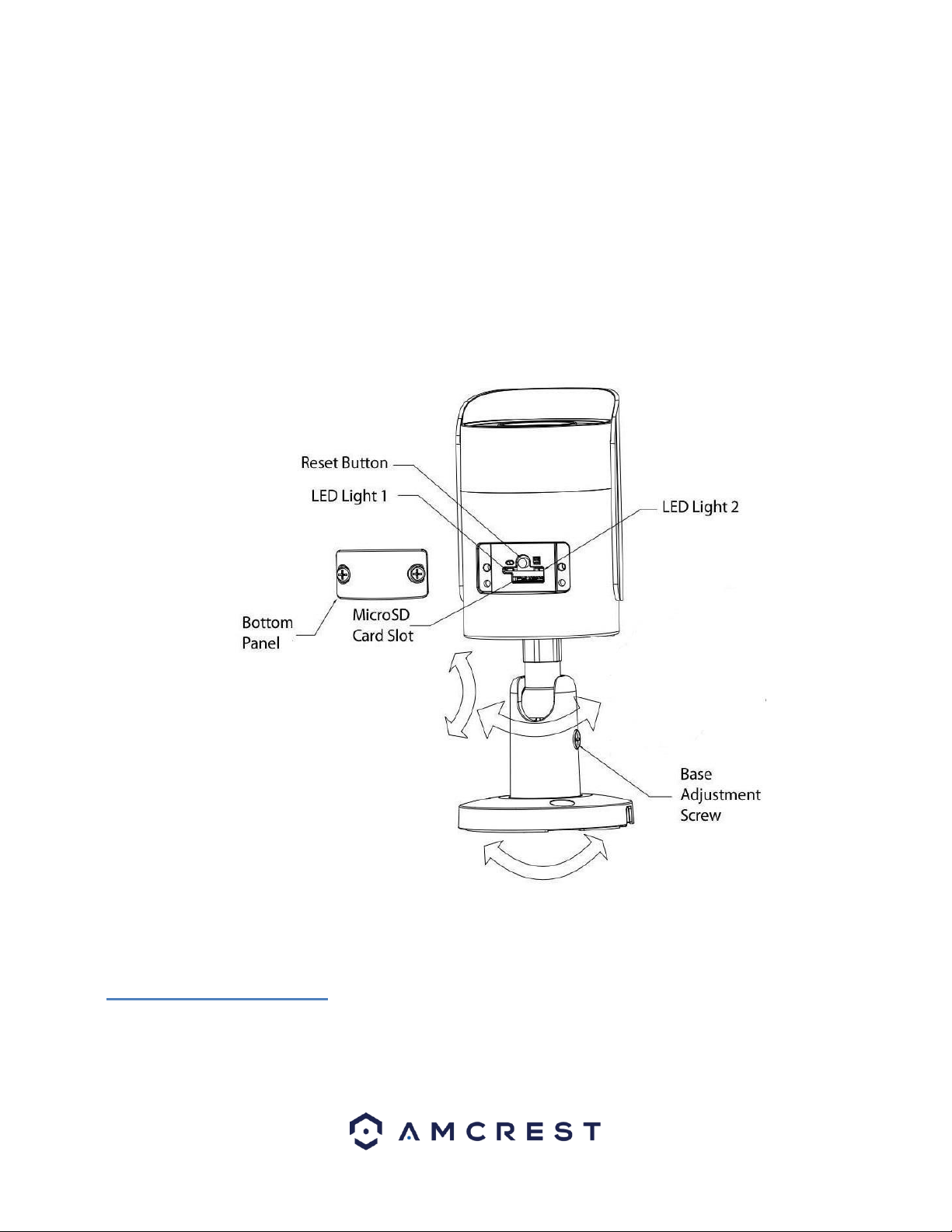
2 Device Overview
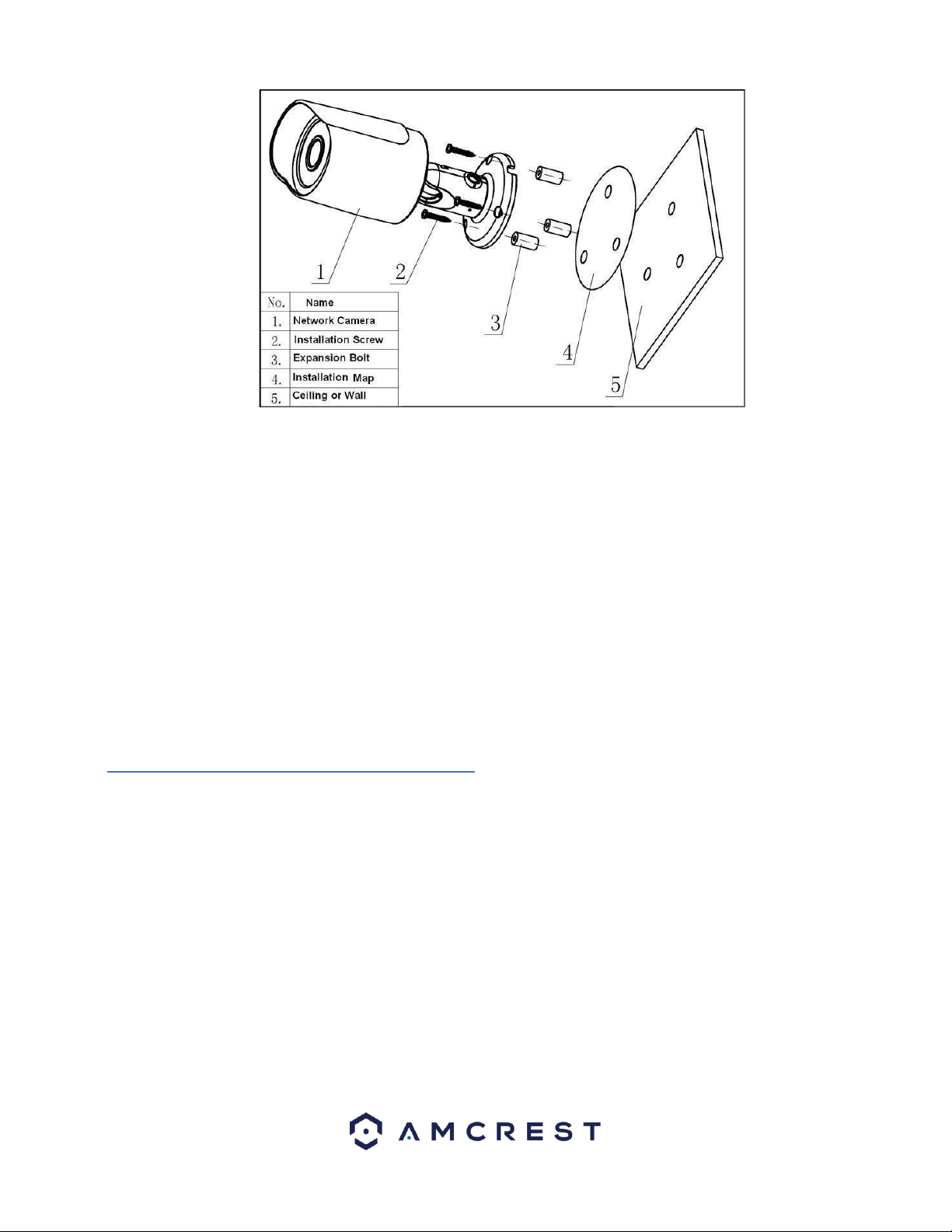
Please refer to the following chart for information about the camera and its ports.
3 Connection & Installation
This section provides information about the connection and installation of Amcrest POE Bullet Cameras.
3.1 Installation Guide
Follow the steps and use the diagram in this section to install the POE cameras.
Note: Prior to installation ensure that the installation environment can support at least 3 times the weight of the camera.
6
1. Stick the installation sticker on the designated surface where the device will be installed (wall or ceiling).
2. Drill 3 holes through the holes on the installation sticker.
3. Open the accessories bag and take out the expansion bolt and insert it into the holes.
4. Open accessories bag and take out the screws. Tighten the 3 screws to fix the device on the installation surface (wall or
ceiling).
5. Loosen the sunshade screw to move it around to the desired position, then tighten the screw to lock it into place.
6. Plug in the camera to power it, using either an Ethernet or power cable.
7. Using a Philip’s head screwdriver, (not included) loosen the adjusting screw near the base of the camera. This allows the
camera to be rotated, as well as pivoted within the ball joint.
8. Adjust the device to the desired position.
9. Using a Philip’s head screwdriver, (not included) tighten the adjusting screw near the base of the camera to lock the camera
in position.
Note: The process for mounting the eyeball camera is similar, but some of the steps may vary
3.2 MicroSD Card Installation Guide
To Install a microSD card into your camera, please refer to the step by step guide below:
Note: You will need a basic Phillips head screwdriver to complete the installation.
1. Locate and remove the protective plate located on the bottom portion of the camera. This plate can be found right above
the serial number sticker of the unit.
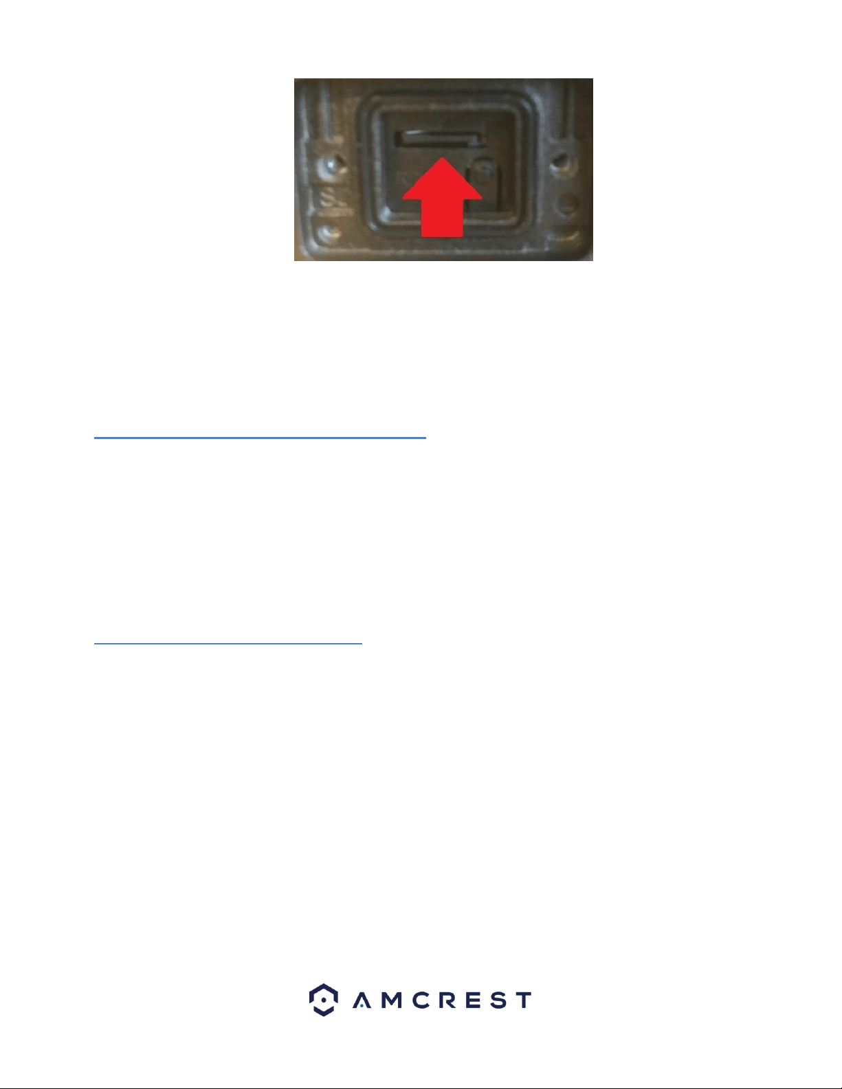
2. Remove the protective plate with a Phillips head screwdriver and locate the microSD card slot for the camera. It is located
right above the factory reset switch.
3. Insert the microSD card into the slot, gold pins down and press into place to lock the micro SD card in the slot.
7
4. Once the microSD card is properly inserted, close the protective plate securely to complete the installation.
4 Camera Access Setup
This section of the guide will provide the user with information on how to setup access to the camera through any of the
following methods.
4.1 Default Username and Password
To login to the system for the first time, use one of the following default username/password combinations. Once you’ve
successfully logged in, it is highly recommended to change the password for security reasons.
Username: admin
Password: admin
Note: Logging in for the first time will prompt the user to change the password to the admin account.
4.2 How to Setup the Camera
To make your experience with your Amcrest camera easy and simple, we've provided multiple ways to set up, view, and
operate your camera depending on your needs. Please follow the instructions on this page to set up your camera in the way
that works best for you.
4.2.1 Setting up Your Camera for the First Time
If you are setting up your camera for the first time, or you are setting up your camera for mobile viewing, please follow the
instructions as outlined on section 4.3. Using the Amcrest Cloud app or Amcrest View app on your smartphone or tablet, you
can view your camera live from anywhere, and access features such as taking snapshots, creating recordings, and more.
4.2.1 For Configuring Advanced Settings on Your Camera
If you would like to configure your camera to enable advanced features such as motion direction, e-mail alerts, FTP, image
adjustments, scheduling and more, please follow the instructions as outlined on section 4.4 (Desktop Access).
4.2.3 For Cloud Storage and Playback
Amcrest Cloud is our optional cloud storage and playback service which allows you to access recorded footage from any
device. We offer 4 hours of free storage for your first camera. Please follow the instructions as outlined on section 4.5
(Cloud Access) to sign up for our Amcrest Cloud service and get 4 hours of free storage.

8
4.2.4 For Quick Web Access to Your Cameras
AmcrestView.com is a web portal that allows you to view your cameras and recordings quickly and easily from anywhere in
the world using a web browser. Use AmcrestView.com if you need to simply check-in at a moment's notice. If you would like
to use AmcrestView.com, please follow the instructions outlined on section 4.6 (Web Access).
4.3 App Setup
Amcrest cameras can be used on your mobile device using the following apps:
• Amcrest Cloud
• Amcrest View Pro
Both apps are free and available in the App Store and Google Play store. Please note, each app requires an iOS 6.0 or later
version. Android will require a 3.0 or later version OS to run these apps.
For purposes of this guide, we will use iOS, though both apps. The App Interface may differ slightly from the screenshots
below as updates are released. Below, you'll find instructions on how to set up your camera up on the Amcrest cloud app as
well as the Amcrest View Pro app.
4.3.1. Amcrest Cloud App Setup
Amcrest Cloud allows you to access your device from anywhere in the world. Please note, you will need an Amcrest Cloud
account to proceed with Amcrest Cloud app setup. You can register for a cloud account in the Amcrest Cloud app or from
the Amcrest Cloud website at amcrestcloud.com
• Please make sure your camera is plugged into a power source and your Ethernet cable is connected from the
camera to your router.
• Make sure your camera and mobile device are on the same network during setup.
• To ensure the camera connects to the cloud, a reboot of your camera is recommended.
To add your camera onto the Amcrest Cloud app, follow these steps:
1. Download and open the Amcrest Cloud app from the App Store or Play Store.
Note: Connect your mobile device to the same network that your camera is on.
2. Register for an Amcrest Cloud account. To register click on Sign Up and fill out the form to complete registration.
9
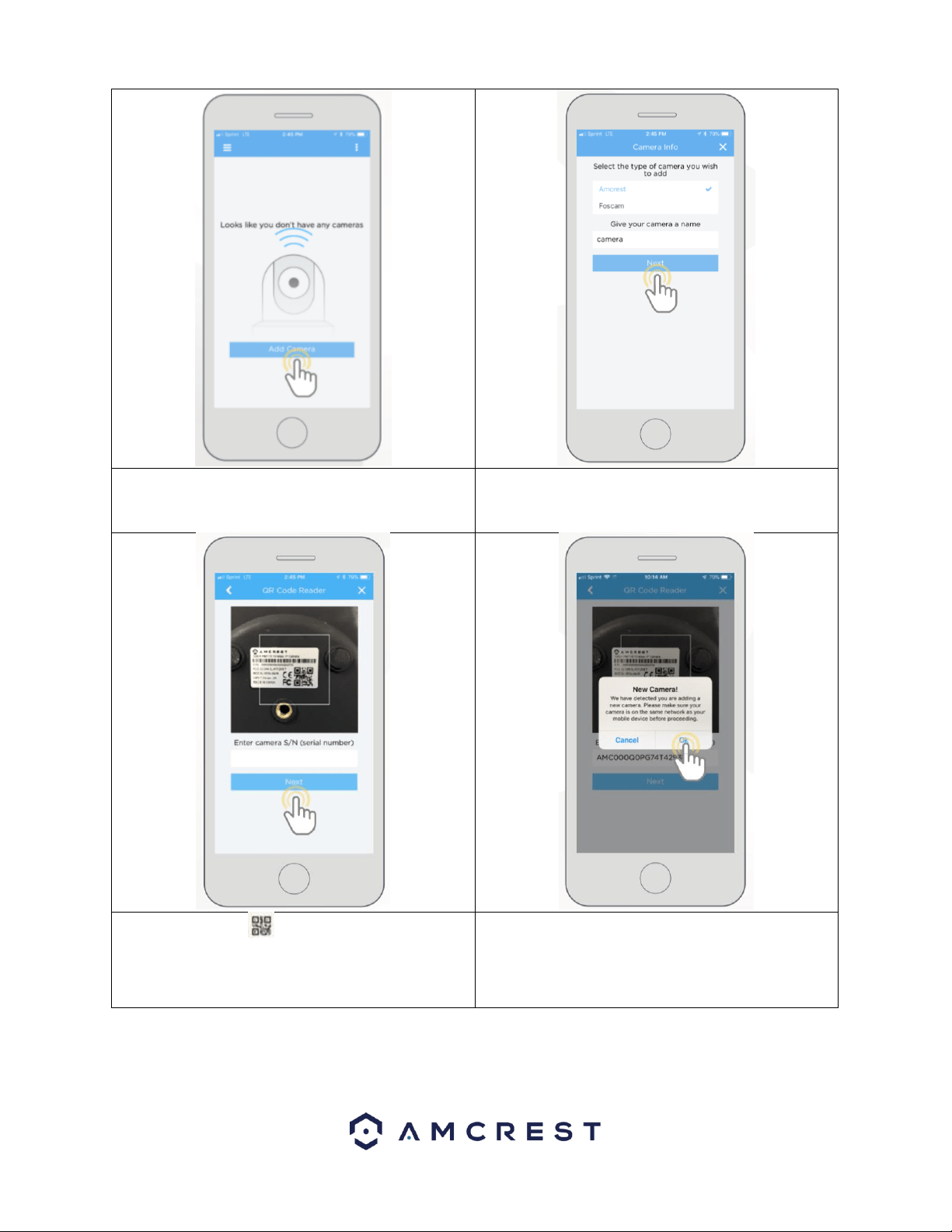
3. Tap on Add Camera
4. Give your camera a name (Ex. Garage, Living Room,
Kitchen, etc.) and tap Next to continue.
5. Scan the QR code on the back/side/bottom of
the camera or manually enter the camera’s serial
number into the Enter camera S/N (serial number)
field. Press Next to continue.
6. If you are adding a new camera that does not have a
set password the app will automatically detect that a
new camera is being added. Tap OK to proceed.
10
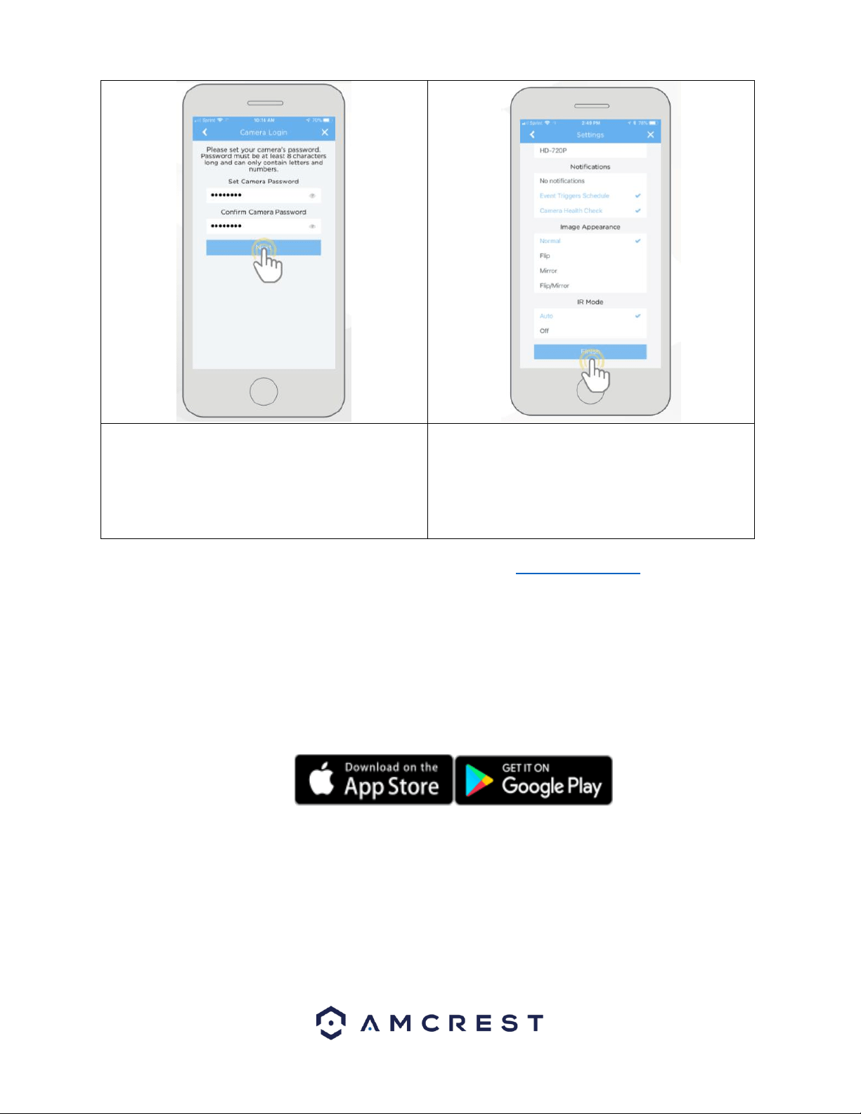
7. Set a new password for your camera. The password
must be between 8 to 32 characters long and contain
only letters and numbers. When you have finished
setting the password for your camera, enter the
password again in the Confirm Camera Password
section. Tap Next to continue.
8. Confirm and adjust any needed settings for your
camera. When all settings have been confirmed, tap
Finish.
For more information about the Amcrest Cloud app and its features, visit amcrest.com/support
4.3.2. Amcrest View Pro Setup
To add your PoE camera to the Amcrest View Pro app follow these steps:
• Make sure your camera is plugged into a power source and your Ethernet cable is connected from the camera to your
router.
• Make sure your camera and mobile device are on the same network during setup.
1. Download and open the Amcrest View Pro app from the App Store or Play Store.
11
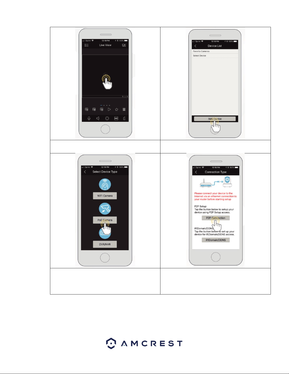
2. Open the app and tap on the + symbol in the middle
of the screen to begin adding your PoE device.
3. Tap on Add Device to add a new device to your app.
4. Tap on PoE Camera
5. Next, select a connection type. Since we will be
setting up a basic P2P connection with the device, tap
on "P2P Connection" to continue.
12
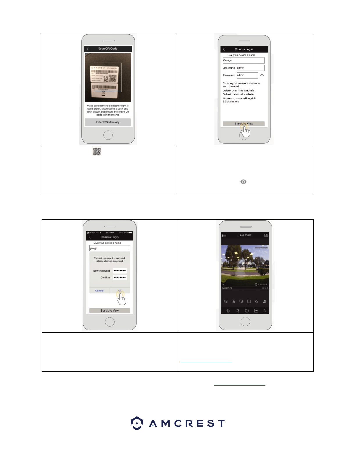
6. Scan the QR code on the back/side/bottom of
the camera or manually enter the camera’s serial
number into the Enter camera S/N (serial number)
field. Press Next to continue.
7. Give the camera a name (e.g. Garage, Kitchen,
Living Room, etc.) and provide the username and
password for your camera. The default username and
will be admin. Tap Start Live View to continue.
Note: You can tap on the icon to verify the
password.
Note: Android users, tap on Scan QR Code to access the QR code reader.
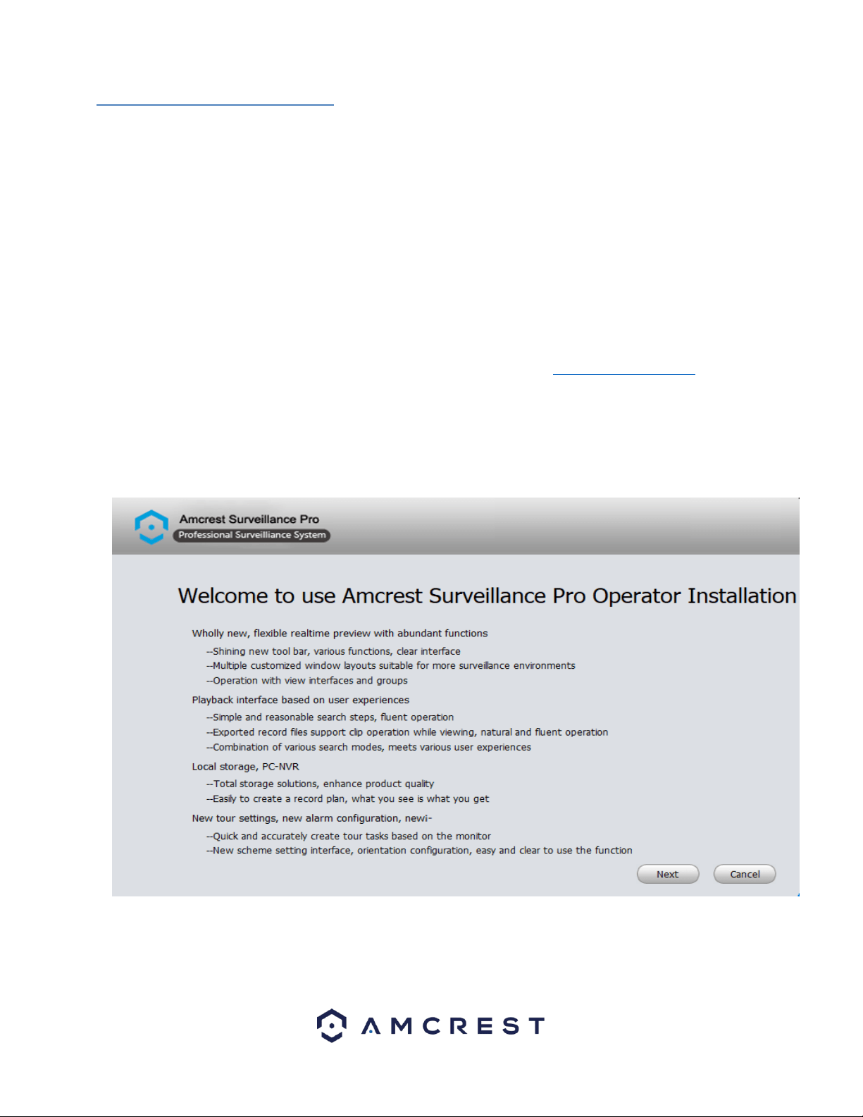
8. The app will prompt you to change the password.
Enter a password between 8 and 32 characters and
confirm the password. Press OK to continue.
9. Your camera is now set up and ready for use on the
Amcrest View Pro app. For more information about
Amcrest View Pro and its functionalities visit
amcrest.com/support
For more information about Amcrest View Pro and its functionalities visit amcrest.com/support
13
4.4 Desktop Access Setup
NPAPI plugins have been recently depreciated by most mainstream web browsers such as Google Chrome, Outlook, and
Firefox. Amcrest is pushing forward to create new and diverse ways for you to more easily access your devices from
anywhere at any time. This document was created to provide a general overview and understanding on how to best access
your device from your computer.
4.4.1. Amcrest Surveillance Pro
Amcrest Surveillance Pro is an abbreviation for Professional Surveillance System. This software the most stable and
recommended method of accessing your devices from your computer. It is a free software provided by Amcrest that can
provide a means of accessing all your devices in one central location without the use of a plugin or web browser.
Note: Mac users, Amcrest Surveillance Pro currently functions as a 32-bit platform and may not be compatible with certain
64-bit Mac operating systems.
Installation
To install the Amcrest Surveillance Pro software on your computer, please visit amcrest.com/downloads In the All
Downloads page you will notice separate sections for Mac OS and PC/Windows downloads for the free Amcrest
Surveillance Pro software. Click on the option that applies to your computer’s operating system to begin installing the
software.
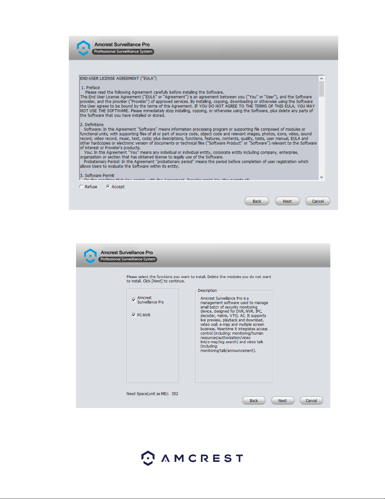
To install the software, double click the Amcrest_Surveillance_Pro_Setup.exe to begin the installation.
Click Next to continue. Please read the End-User License Agreement (“EULA”) carefully and click the Accept radio button
when finished to agree. Once accepted, click the Next button to continue.
14
Select the functions that you want to install with the software. You can choose to bundle the PC-NVR function with the
software. PC-NVR turns your computer into an NVR and will utilize your hard drive (HDD) on your PC to store and access
recorded video. To proceed with the installation, click Next.
Select the destination folder in which you would like recorded files to be retained. To choose a folder, click on the Browse
button and select the folder. Once a folder has been selected, click the Install button to begin installing the software on
your computer.
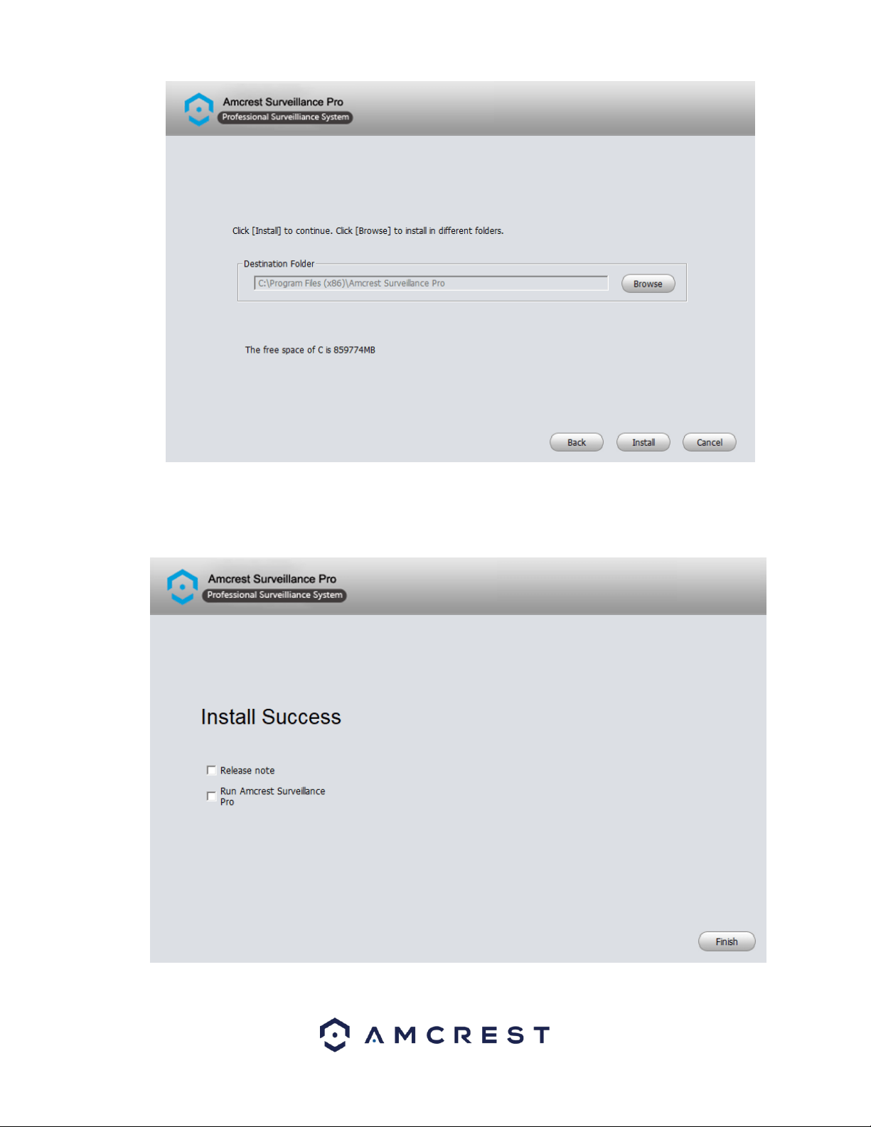
15
Once the software has finished installing you will see a few options. You will have the options to view the release note and
run the Amcrest Surveillance Pro software. To view the release notes after pressing Finish select the Release note
checkbox. To begin running the software directly after pressing finish, select the Run Amcrest Surveillance Pro checkbox.
When complete, click the Finish button to proceed.
16
Setting a Password
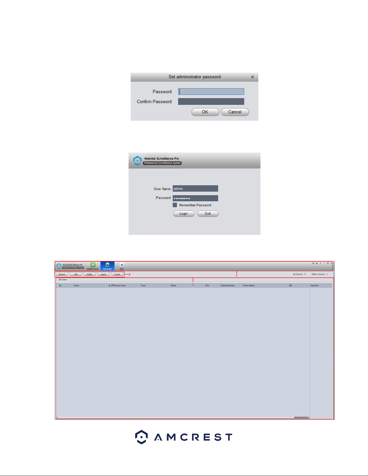
After the installation of the Amcrest Surveillance Pro software you will need to set an administrator password. This
password will be set password for the admin account on the software. When a valid password has been entered, confirm
the password in the Confirm Password field and click OK to continue.
Type the created password into the Password field on the next screen and click Login to log into the software. If you do not
wish to have to retype your password every time you log into the system, click on the Remember Password checkbox. If
you wish to exit the software, click Exit.
Main Interface Overview
When you first log into the software you will be taken to the main interface of the software.
17
Below is a description of the items listed in this menu.
Menu
In this section you can view the home page icons and any currently open functions in the
software. Click the Add button to add a function icon to the top pane.
Settings Menu
This menu allows you to Search, Add, Delete, or Import, and Export settings of devices
connected to your network.
All Devices
This menu allows you to view all added devices associated with the software.
Adding Devices into Amcrest Surveillance Pro
To provide the highest efficiency and security when adding a device into the Amcrest Surveillance Pro software it is highly
recommended to add the device using a direct IP address as opposed to using a P2P connection. Using a direct IP provides a
direct connection to your device without the use of utilizing a P2P server.
Direct IP Connection
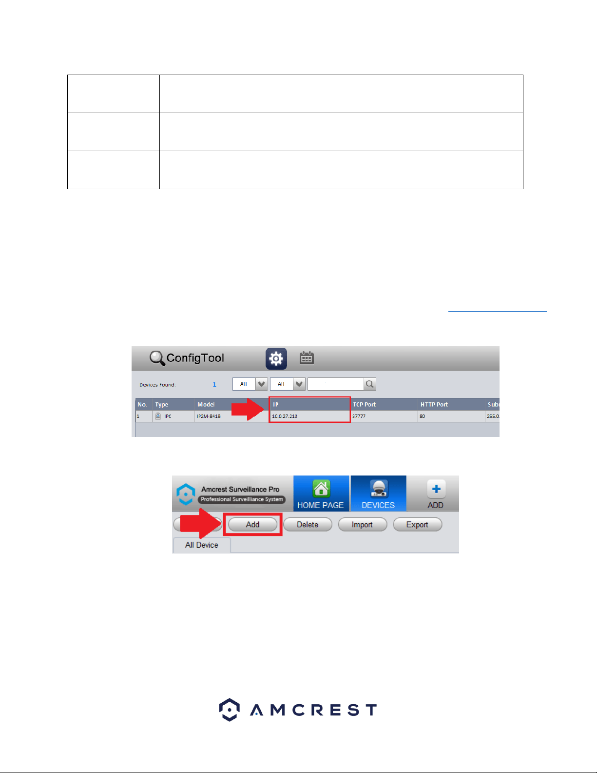
To begin adding a camera, you will need the IP address of the device. To obtain the IP address for your device, it is
recommended to download the Amcrest IP Config tool. To get the Amcrest IP Config tool, go to amcrest.com/downloads
and click on the IP Config software link for either PC/Windows or Mac OS. Launch the IP Config tool and locate the IP
address for your device. The IP address will be listed in the IP field of the software.
After locating the IP address in the Amcrest IP Config tool for the device, return to the Amcrest Surveillance Pro software
and click on the Add button.
In the add menu, enter a name you would like to assign to your device. In this example, we are using “Front Door Camera”.
Next, in the Method to add menu, use the default setting “IP/Domain”, then enter the IP address and port number of the
device being added. As a reminder, the IP and port number of the device can be located in the IP Config software. The group
name will then be applied as Default Group, then enter the user name and password for your device. If this is the first time
using your device, the default username and password will be admin. Click the Save and Continue or Add buttons to
proceed.
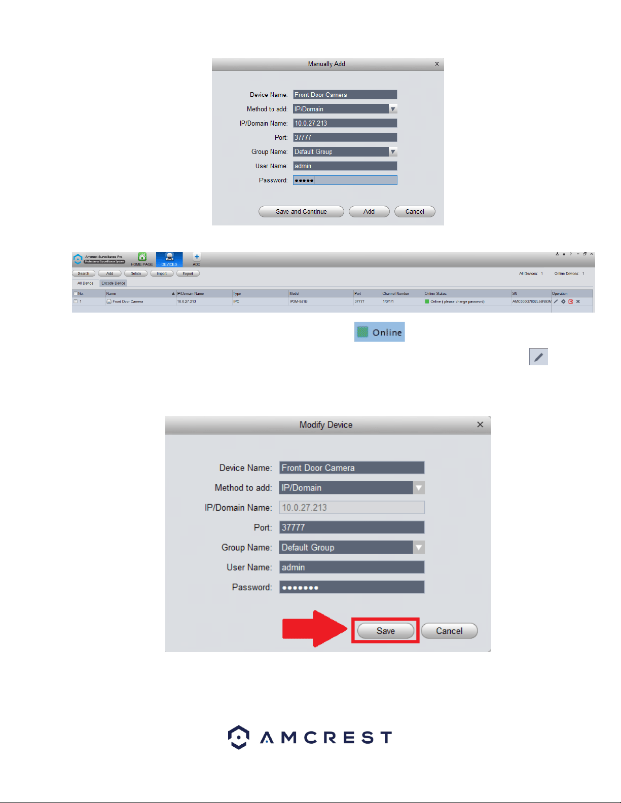
18
Once the device has been properly added the added device will appear in the Device menu.
If the device is properly connected in the software, you will notice a icon in the Online Status field. If the device
is not connected properly, click on the online status will be red. To modify settings for your device, click on the icon
located in the Operation menu. This menu allows to rename the camera as well as change the port number, username, and
password. To update the password, remove the default password and type the new password in this field. When done, click
on Save to save the information for the device.
Setting a Device to a Static IP
For security purposes it is highly recommended to set the camera to a static IP address. Setting your device to a static IP will
ensure the stability and the efficiency of your device while operating it in the Amcrest Surveillance Pro software. To set your
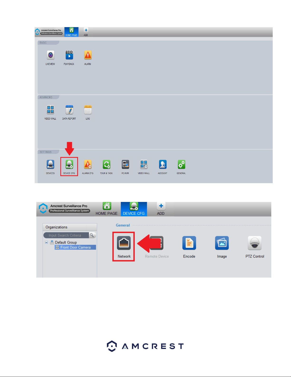
device to a static IP, click on the Home Page icon and navigate to the Device Config menu.
19
In the Organizations menu on the far left, click on the device you wish to modify. Then In the device configuration menu,
under General click on the Network icon to access the network settings for your device.
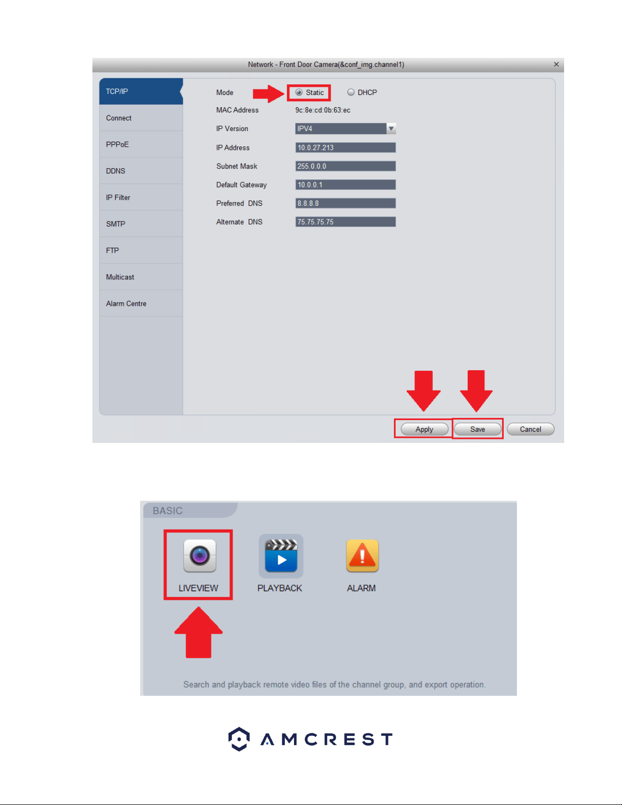
In the Network Settings menu, in the Mode section click on the Static radio button to set your device to a static IP. Click
Save and Apply to apply the network settings to your device.
20
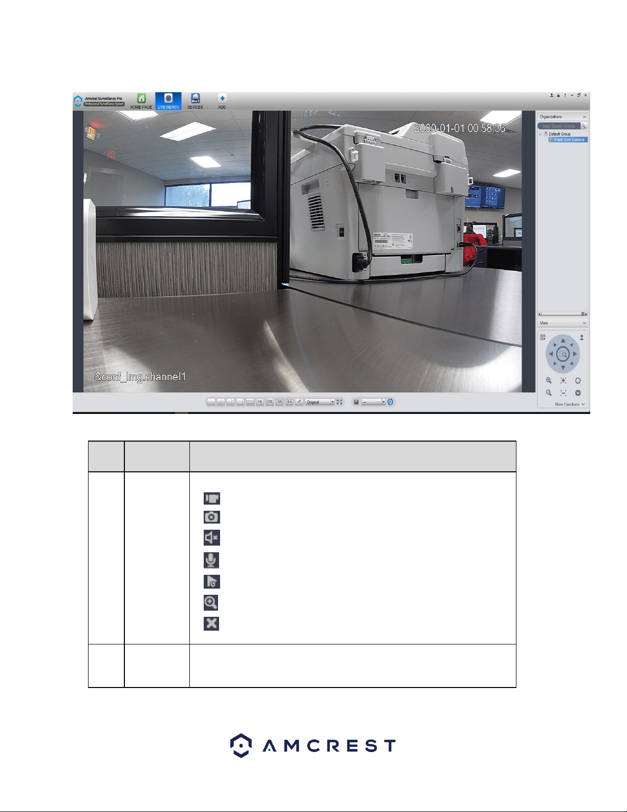
Viewing an Added Device
To begin viewing an added device, navigate to the Home Page of the software and click on the LIVEVIEW icon located in the
Basic section.
21
In the Organizations menu, on the far-right side of the live view screen, double-click the device you want to view to load the
live feed into the viewer.
For more details on the features listed in this menu, refer to the table provided below:
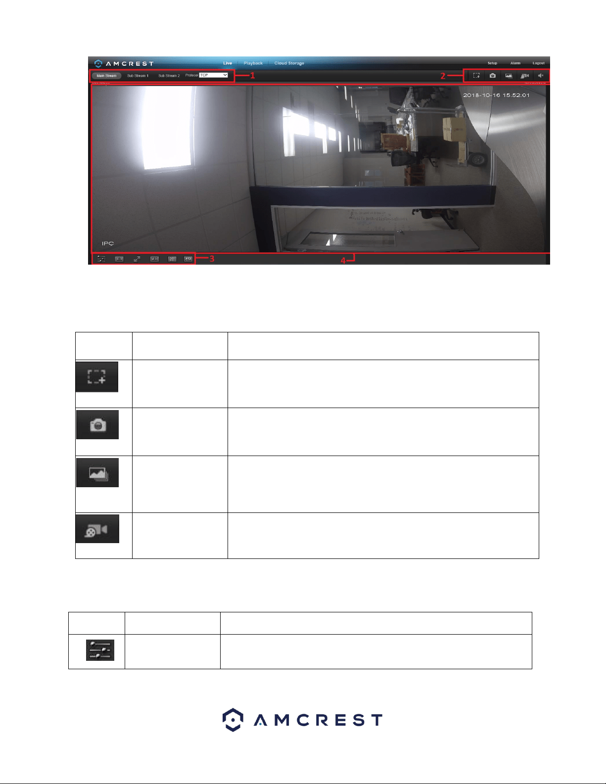
SN
Item
Function
1
Bit stream
information
and shortcut
operation
menu
Please refer to the following contents for detailed information.
⚫ : Enable/disable local record.
⚫ : Snapshot.
⚫ : Enable/disable audio.
⚫ : Enable/disable bidirectional talk.
⚫ : Instant playback.
⚫ : Digital zoom
⚫ : Close current window.
2
Video
window
Real-time video
22
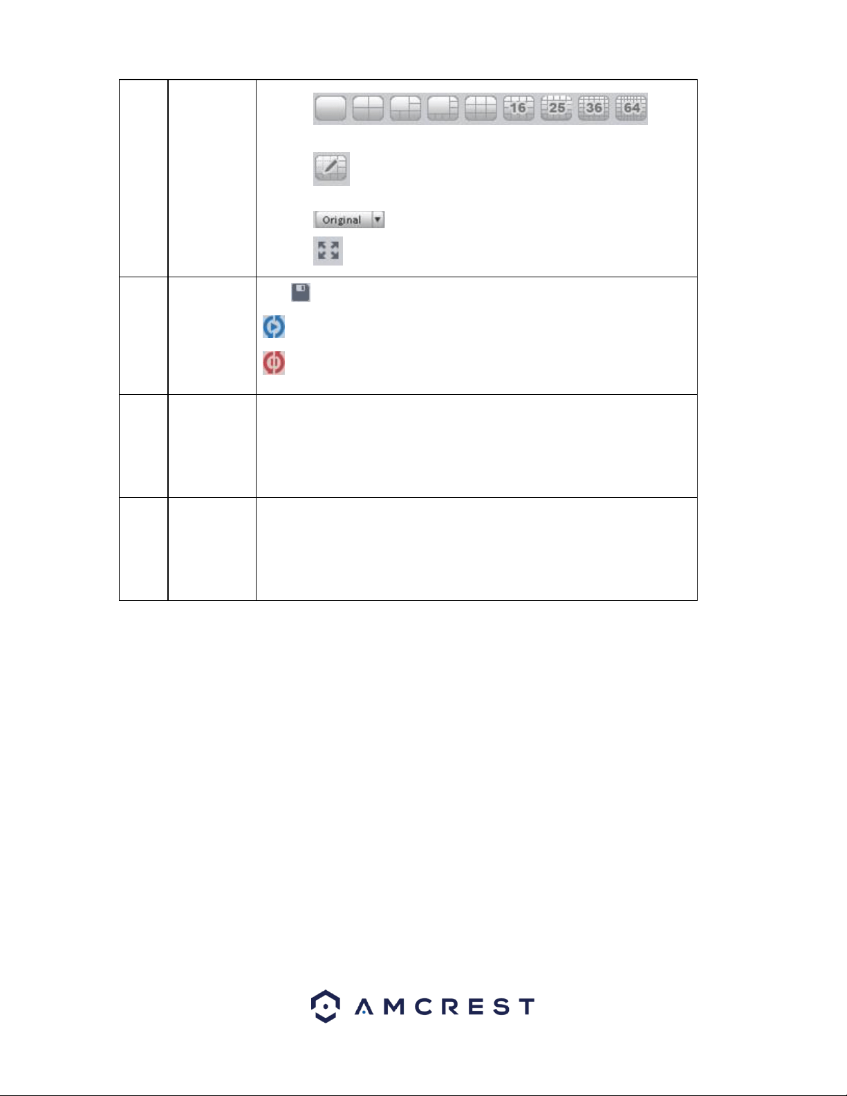
3
Window
split mode
⚫
Sets the live view to 1- 64-window mode.
⚫ : Select a window and then click this button to customize its
setup.
⚫ : Adjust video scale.
⚫ : Full screen.
4
Intelligent
button
:Save current liveview as image. You can view under View.
:Enable tour plan.
:Close tour plan.
5
PTZ
It is for PTZ dome camera or fisheye camera series product only. Here you
can set camera direction, zoom in, zoom out, iris, etc.
Click the advanced button to set preset, tour, aux function or other settings
related to PTZ.
6
Device list
Display device group and the corresponding channel.
Here you can create a new group and drag a device to it.
Right click a channel, you can select main stream/sub stream or quickly go to
the device setup interface.
How to Setup PC-NVR
PC-NVR allows your device to record directly to your computer’s hard drive. To setup PC-NVR on your computer, follow the
instructions set provided below.
Note: PC-NVR is not compatible with MacOS. PC-NVR is only compatible with Windows based operating systems.
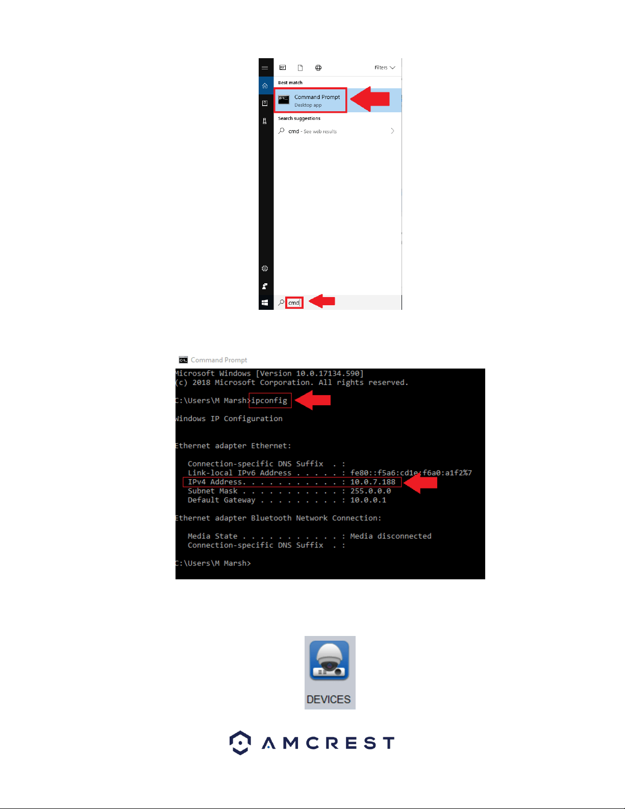
To begin setting up PC-NVR, navigate to the command prompt menu for your computer. The command prompt can be
found by typing “cmd” in the Type here to search (Cortona) option on your desktop. Click on Command Prompt.
23
In the command prompt menu, type in ipconfig to access the IPv4 Address for your computer.
When the IPv4 address for your computer has been located, navigate back to the home page in the Amcrest Surveillance
Pro software and click on the Devices icon located in the Settings menu.
24
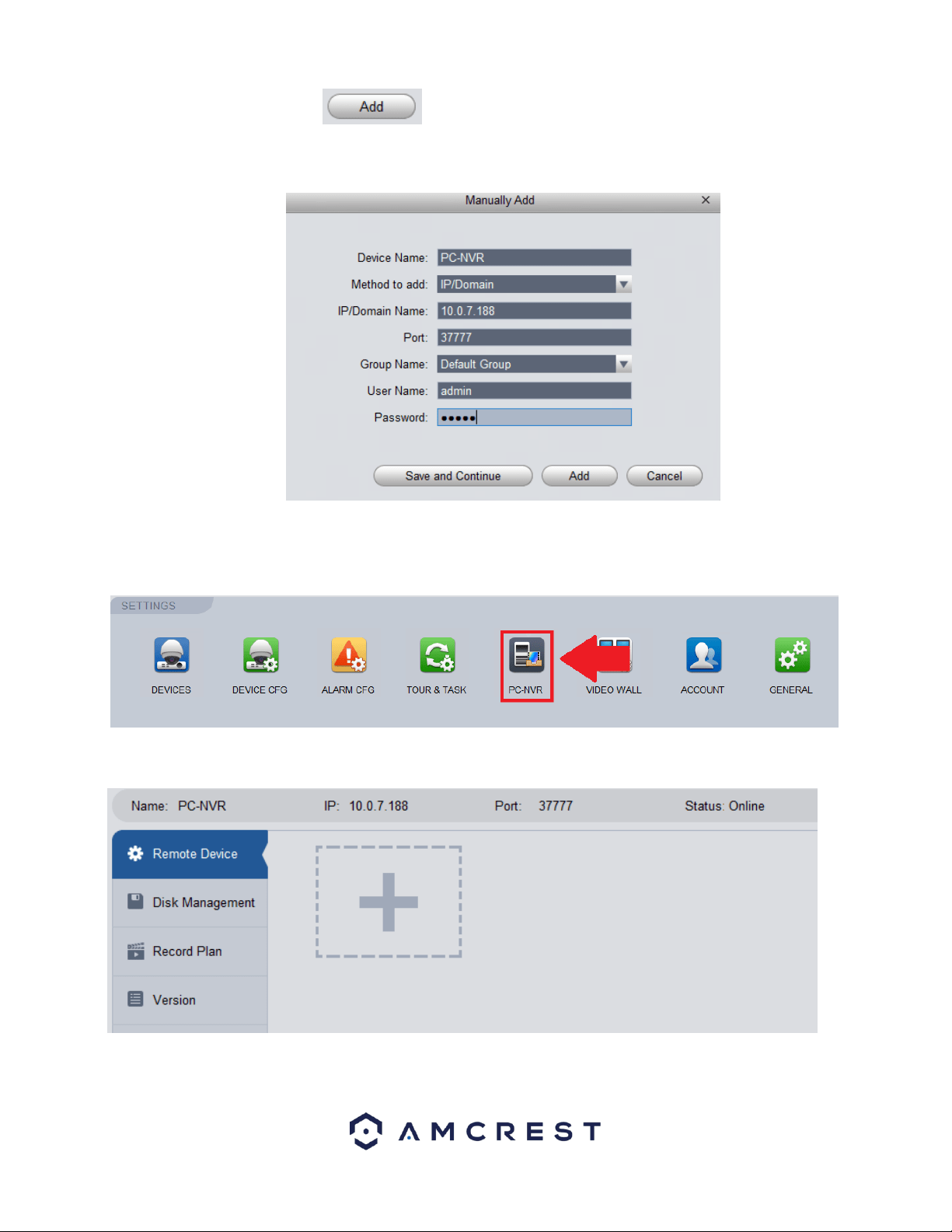
In the Devices menu, click on the button. In the Manually Add screen enter a name, preferably “PC-NVR”
and in the IP/Domain Name field, enter the IPv4 Address from the command prompt screen. Lastly, enter the username
and password. The username and password will both be admin. When complete, press Save and Continue to proceed.
The PC-NVR entry will then be added into the Devices menu.
To enable PC-NVR, navigate to the Home Page and in the Settings menu, click on the PC-NVR icon.
Once the PC-NVR tab opens, you will find your PC-NVR details, select Remote Device.
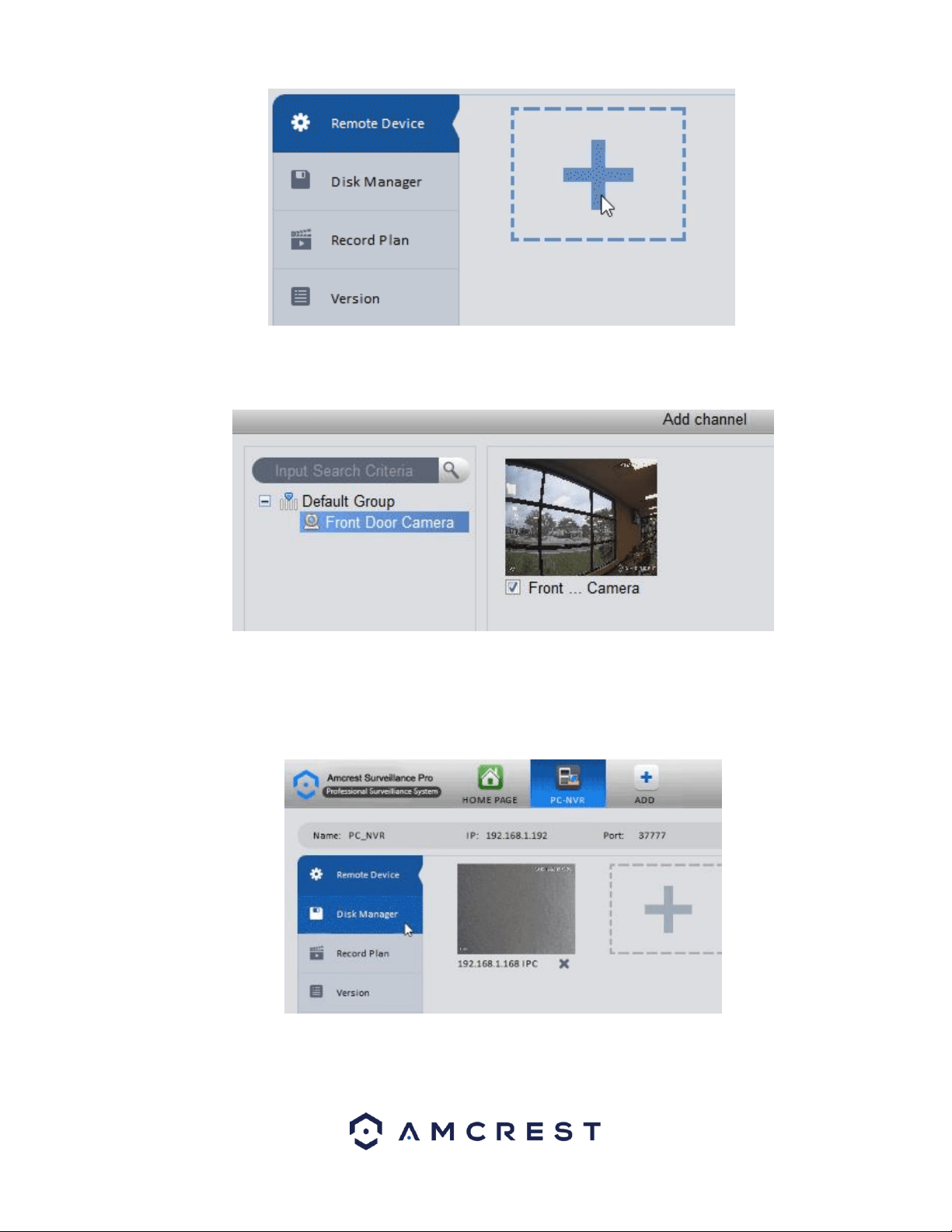
Click on the Plus button to add a camera from the cameras you have connected to Amcrest Surveillance Pro.
25
The Add Channel window will appear, select your camera from the Default Group or Custom Group list you’ve
created.
The camera will appear in the right screen, check the IPCamera check box. Click Save.
How to Setup Storage for PC-NVR Recording
Access the PC-NVR menu and navigate to the Disk Manager tab in the far-left corner of the screen.
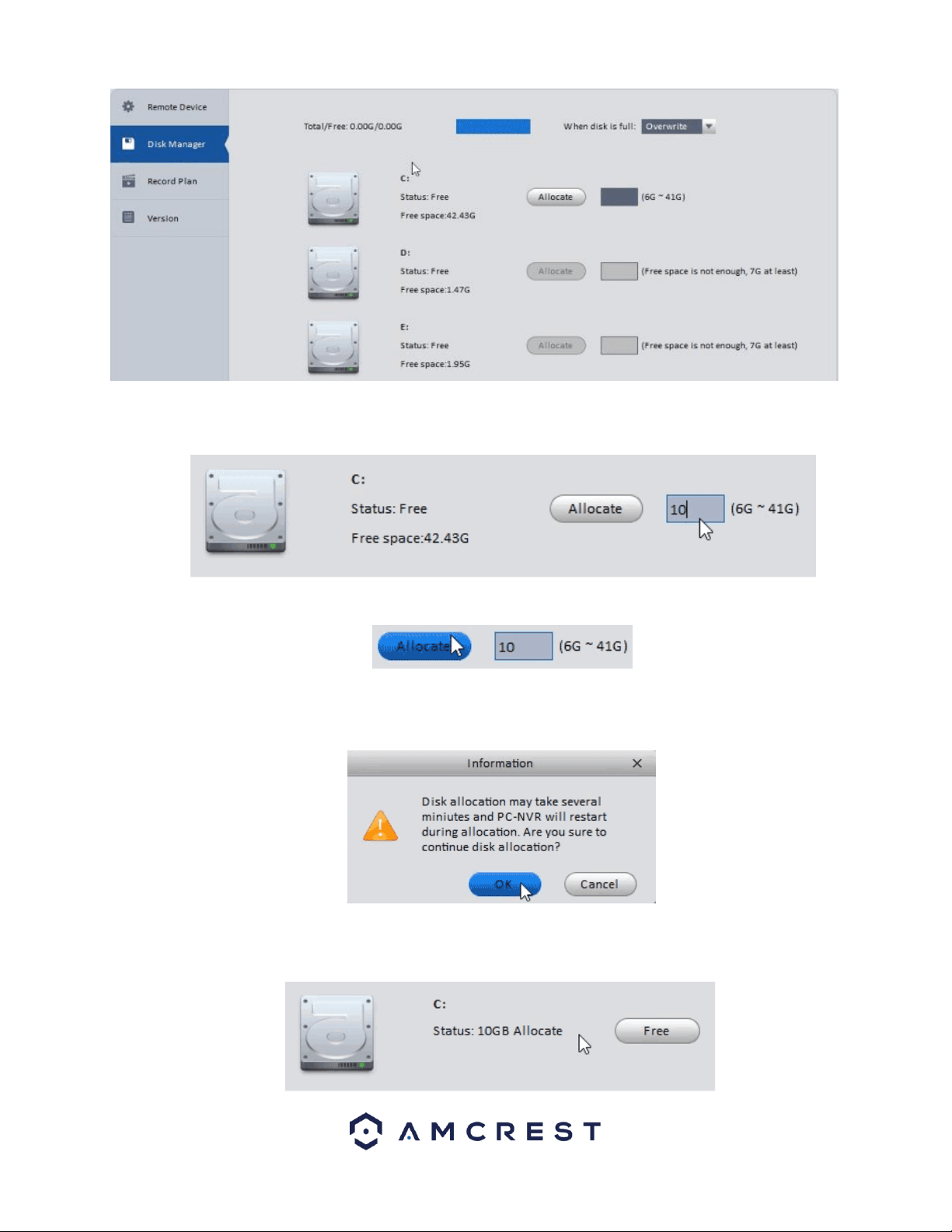
Disk Manager will appear showing you a list of drives that could be used to allocate storage space for your cameras through
Amcrest Surveillance Pro.
26
Select a disk you would wish to use for recording purposes, you may allocate as much space as you have available on the
drive within its minimum and maximum allowance.
Once you’ve set a number between the possible storage sizes, click Allocate.
A prompt window will appear to warn you the allocation may take several minutes, and the application will restart after
completion. Click OK to begin the allocation.
You will notice the disk you selected will now have the allocated space you selected, and at any point in time you can
select Free to free up the space by wiping that allocation.
27
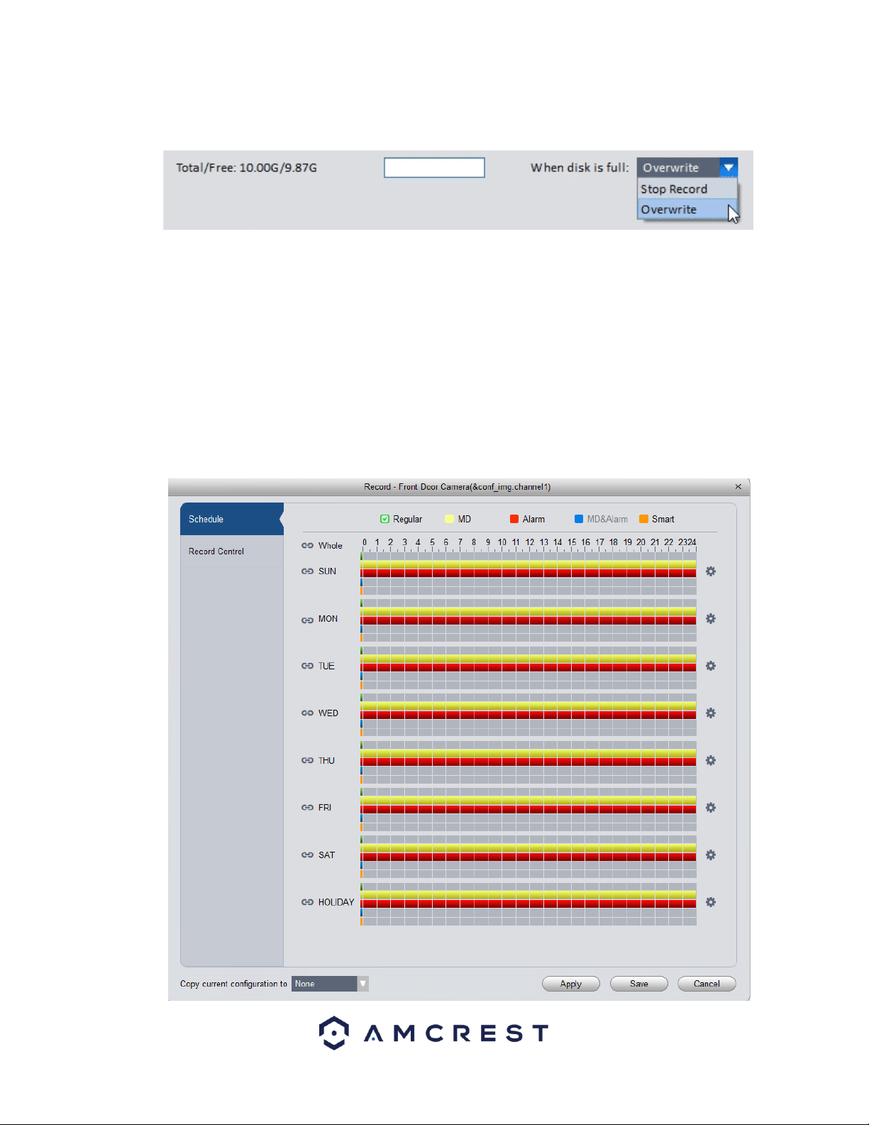
At the top of the Disk Manager window you can select what happens when the disk you’ve allocated gets full. Two
options, Stop Record to end all recordings after the disk is full or Overwrite to continue to save over the oldest recorded
data.
You’ve successfully added your camera to Amcrest Surveillance Pro, turned your computer into a PC-NVR and have the
camera recording any or all the motion events you have set up internally on the cameras main interface.
How to Setup Recording
The Amcrest Surveillance Pro software allows you the opportunity to set your added device to record on motion or on
continuous (general) recording. You can also set recording schedules for your device.
Storage
To begin setting up recording settings for your device, a microSD card or PC-NVR must be established to storage the
recordings. When a storage device has been established in your device, navigate to the Home Page and click on the Device
CFG icon in the settings menu. Select the device you wish to configure and in the Storage field, click on the Record icon.
28
Below is a description of the fields listed in this menu:
Regular
Regular recordings are set to set your device for continuous recording. This field is designated
by a green color in the software.
MD
MD, or Motion Detection recordings, are set to set your device to record on motion detection.
This field is designated by a yellow color in the software
Alarm
Alarm recordings are set to set your device to record only when a specific alarm is triggered.
This is designated by a red color in the software.
MD&Alarm
MD&Alarm, combine both motion detection and alarm settings into on specific attribute. This
field is designated with blue color in the software.
Smart
Smart is set to only apply smart features such as, face detection or other intelligent features,
to trigger recording. Amcrest cameras do not currently support smart features. However, this
is designated with an orange color in the software.
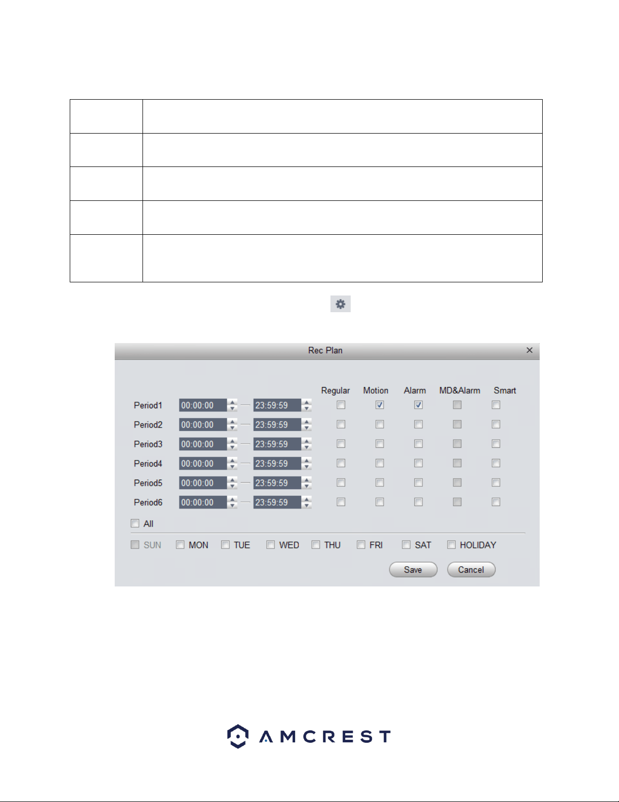
To begin setting a record schedule for your device, click on the icon next to the day you want to schedule your record
plan.
Clicking this button opens a screen that allows for recording periods to be set for each day and for each recording type.
There are a total of 6 periods that can be set. To set a recording schedule, select the record type (Regular, Motion, Alarm,
MD&Alarm, Smart) and select the times you would like your schedule to apply. If you would like the record type to record
24/7 the period will remain on 00:00:00 – 23:59:59.
Next, select which days you would like the schedule to apply with and click Save to continue. If you would like the schedule
to apply to all days, click the All button. On the main record menu, click on Apply and Save to save the schedule to the
software.
29
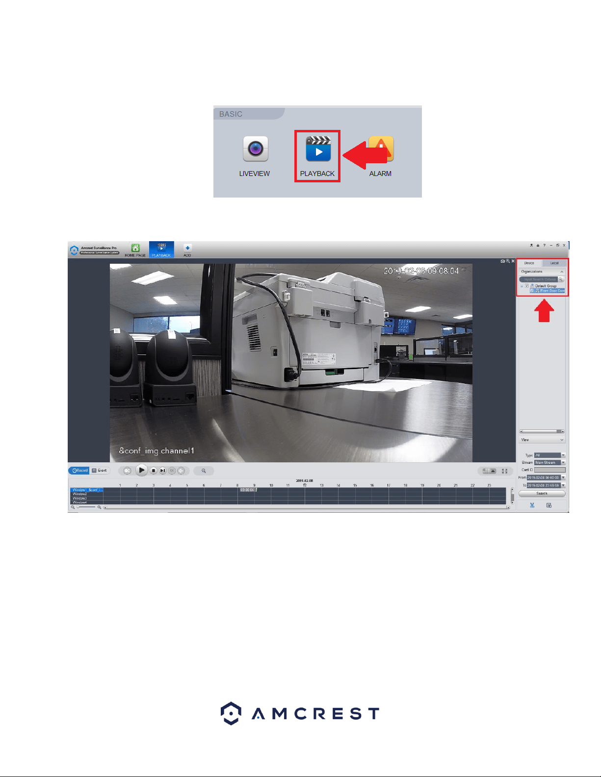
How to View Playback
To playback recorded material in the Amcrest Surveillance Pro software, navigate back to the Home Page and in the Basic
menu, click on Playback.
In the Organizations menu, click on the device you would like to view playback on. Ensure the checkbox next to the device
name and group name are checked.
In the Type dropdown box, select which type of recording you would like to view. To view all records, make sure All is
selected from the drop downbox. Next, ensure the correct stream is enabled in the Stream menu. The default stream will be
Main Stream. Then, select a specified date and time for the file and click on Search.
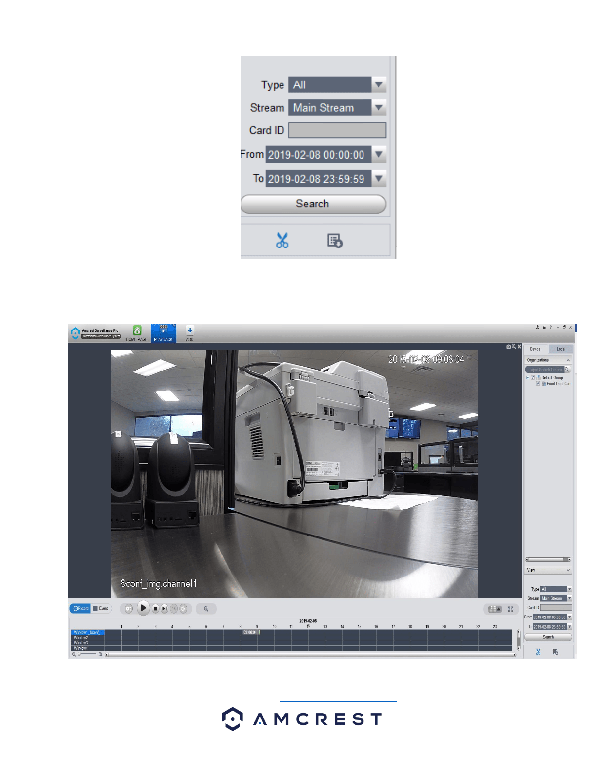
30
The play back controls can now be used to play, stop, skip to next event, control the speed of playback, and mute audio. If
you're viewing more than one camera, on the right-hand side of the play back controls you will find a channel selection drop
down menu to add or remove multiple channels, as well as go full screen.
For more information on the Amcrest Surveillance Pro software and its functionality, please refer to the full Amcrest
Surveillance Pro user manual which can be found at amcrest.com/aspusermanual

31
Access your camera and all its features and settings on your local network using Internet Explorer or Safari on Windows or
Mac.
This method of accessing the camera’s interface is necessary to setup remote access. Ensure that the following items are
completed:
Note: Make sure the camera and the PC are on the same network before proceeding.
Use one of the following web browsers: Safari, Internet Explorer, or the Google Chrome app.
To easily connect to the camera’s interface, install and run the Amcrest IP Config tool. You can download the IP Config
software from www.amcrest.com under the “Support” tab, Apps & Software. The IP Config tool’s interface looks like the
below image:
4.4.2. Amcrest Blue Iris
Blue Iris is professional Windows based surveillance software that allows you to view and record up to 64 IP cameras,
DVR/CCTV based cameras ($59.95 Paid License for 64 Cameras) simultaneously. It is a third-party based, software that is
compatible with a vast majority of IP camera and DVR brands.
In addition, it takes advantage of H.264 video compression allowing you to save hard drive space and reduce bandwidth
consumption. Use Amcrest Blue Iris to turn your existing Windows PC into a fully featured professional video surveillance
system.
For more details about Blue Iris software and its features, please visit http://blueirissoftware.com/
Installation
Blue Iris is a Windows based software, it is not available for Mac or Linux. For this reason, it is recommended for these users
to use Amcrest Surveillance Pro as previously outlined.
To install the Amcrest Blue Iris software on your computer, please visit https://amcrest.com/blue-iris.html and download
the Amcrest Blue Iris (for Windows Only) software to your computer.
Minimum requirements:
• Pentium dual-core or equivalent 2GHz processor or better
• 2GB or more system RAM
• Microsoft Windows XP SP3 or newer, or a server OS
• One or more USB or Network IP cameras, or an analog capture card with DirectShow drivers.
Recommendations when using many and/or HD cameras:
• Intel core i7 with QuickSync for hardware decoding
• 8GB or more RAM
• Microsoft Windows 8.1 or 10, 64 bit
• nVIDIA graphics adaptor for efficient screen display
• 7200+ RPM drives and/or SSD drive
To install the software on your computer, click on the Amcrest+Blue+Iris.exe file to launch the installation wizard. Click
Next to begin the installation process and allow the software to download.
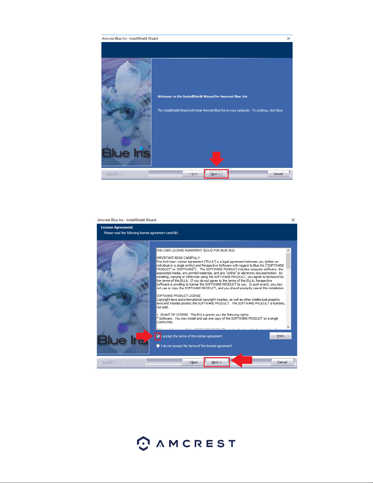
32
Please review the license terms before installing the Amcrest Blue Iris software. Read the license agreement carefully, and
then to accept the terms, click the radio button next to the I accept the terms in the license agreement statement. Click
Next to continue.
Choose a file destination in which you would like the Amcrest Blue Iris software to download. If you would like to specify
another path, besides the default path, click Change. It is recommended to leave the default download path when installing
the software. To continue the installation, click Next.
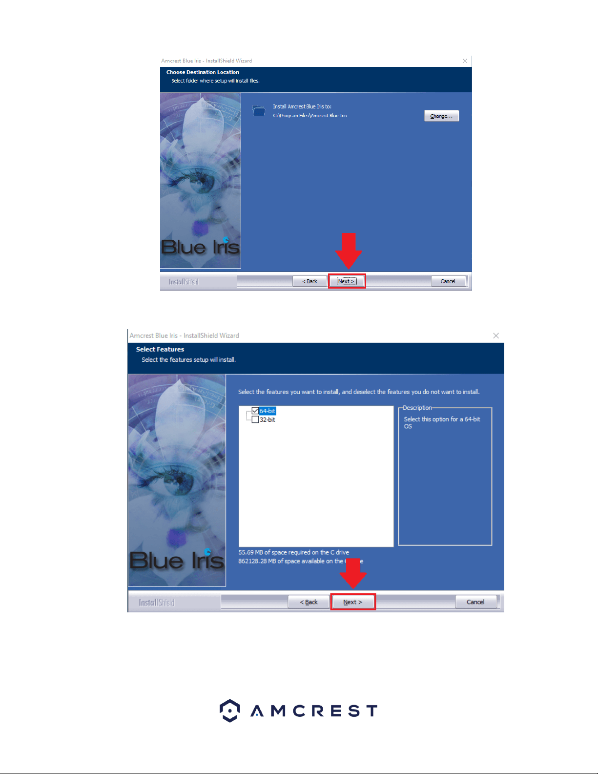
33
Select the features you want to install and deselect the features you do not want to install. If your OS is 64-bit it is highly
recommended to leave this option at 64-bit. To continue, click Next.
To begin installing the software click on the Install button and allow the software to download to your computer.
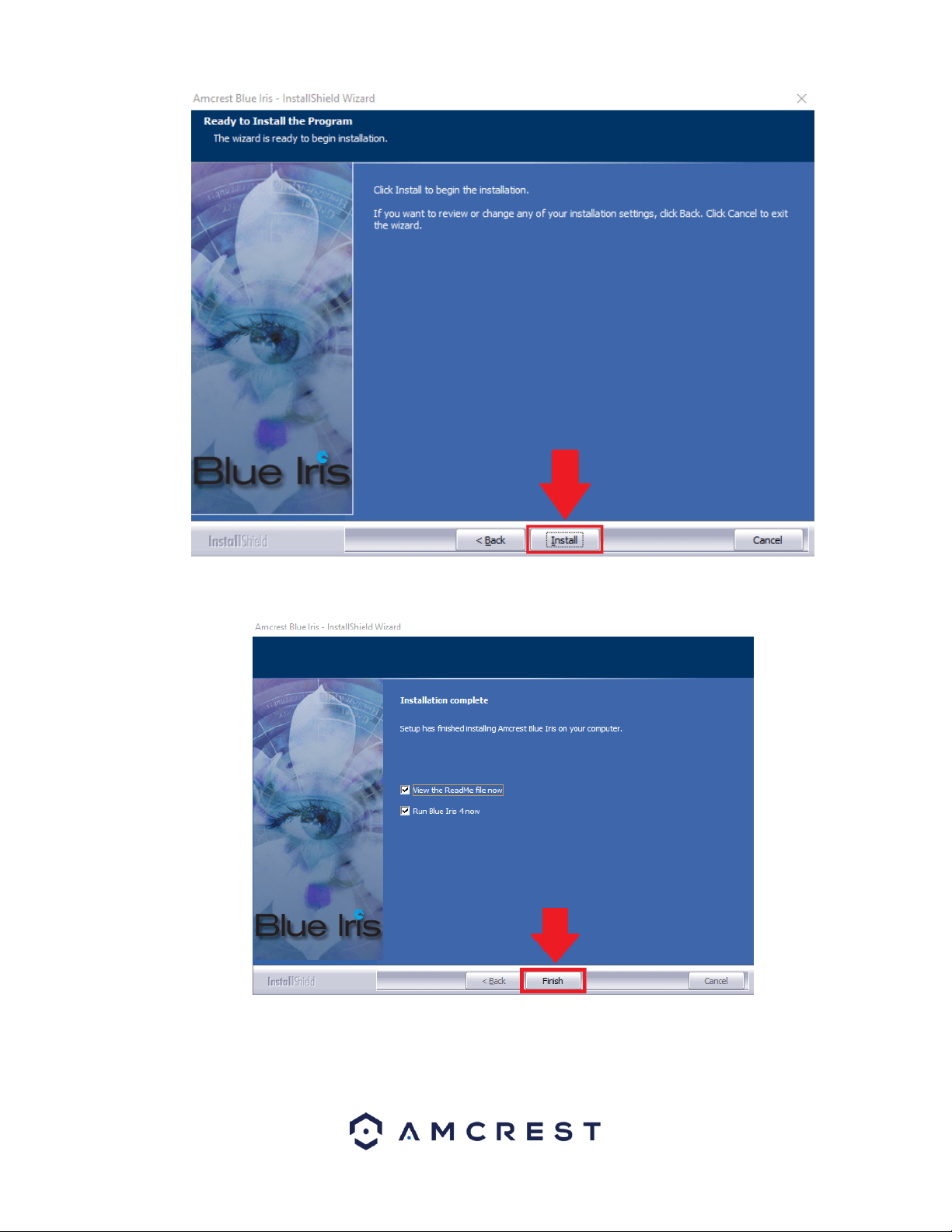
34
When the software has finished downloading, click on the Finish button to launch the software.
Note: if you do not wish to read the ReadMe file for the software, uncheck the View the ReadMe file now checkbox.
35
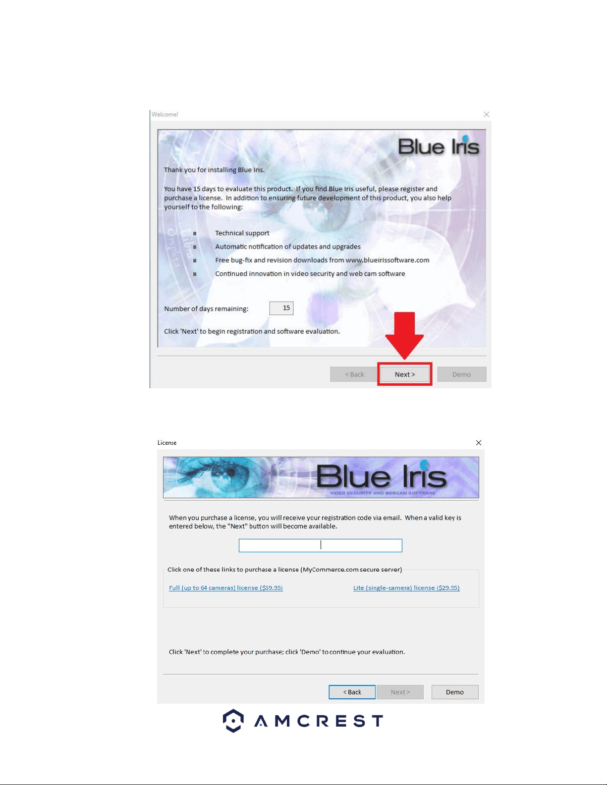
Purchasing an Amcrest Blue Iris License
Amcrest provides a 15-day free trial of the Amcrest Blue Iris software. If you find the Blue Iris software useful, please
register and purchase a license. To continue the free trial version of this software, click Next to continue.
Amcrest offers two versions of the Blue Iris software; Full, and Lite. The full version ($59.95) allows you to use up to 64
cameras with all the added features of Blue Iris. The Lite version allows you to use a single camera on the software with all
the functionality of the software.
36
If you would like to purchase a license, select which license you would like to use and a registration code will be sent to your
email address. When a valid key has been sent, enter the key into the License screen pictured above. If you would like to
proceed with the free trial version, click on Demo to proceed to the evaluation version of the software.
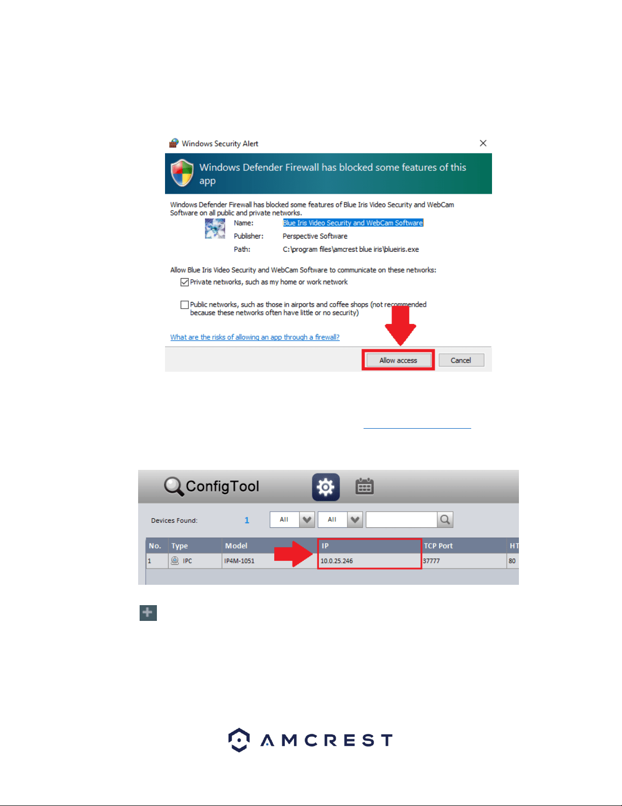
Note: When accessing the software, make sure to Allow access to all communications blocked by Windows Defender.
How To Add a Device Into Blue Iris
To add a device into the Blue Iris software, locate the IP address for your device using the Amcrest IP Config Tool. The
Amcrest IP Config Tool can be downloaded at the following web page: amcerest.com/downloads
In the All Downloads menu, click on IP Config Software to begin the free download. Once the download has completed
installing, locate the IP address associated with the device you would like to view in the browser.
This is the IP address that will be used in the Amcrest Blue Iris Software. To add a device, navigate to the Blue Iris software
and click on the button.
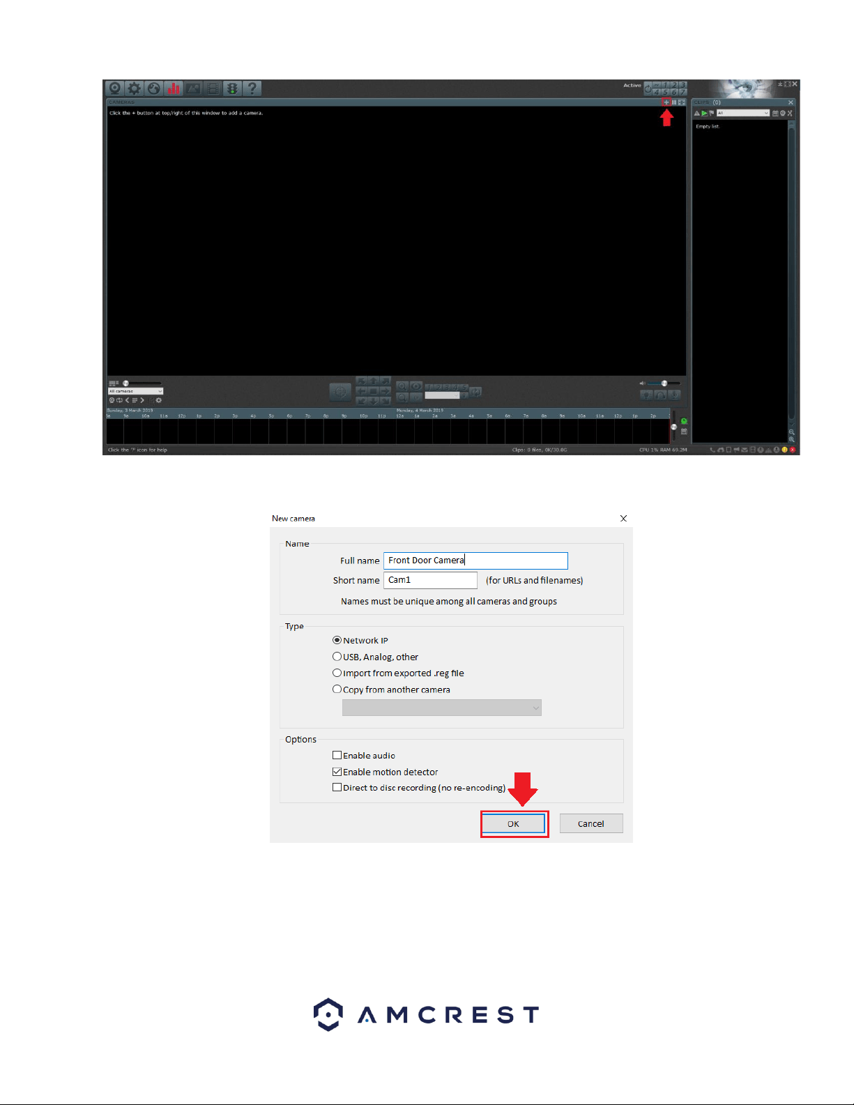
37
In the New Camera menu, provide a name for your camera. This can be a full name and a short name. Select which type of
camera is being added to the software, and enable the options associated with your device. Click OK to continue.
Next, enter the IP address of the device. This is the IP address discovered in the IP config tool. Enter the IP address in the
Address field, then enter the user name and password for your device. If this is the first time using your camera, the
password will be admin. Click OK to continue.
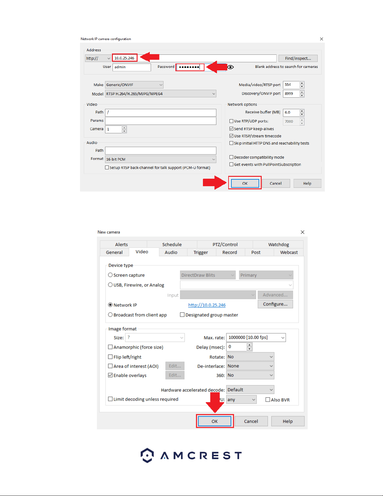
38
The next screen will be the settings menu for your device. In this menu you can set Alerts, Schedules, PTZ/Control, General,
Video, Audio, and other settings associated with your device. Click OK to continue.
The device will now be successfully connected to the Blue Iris software.
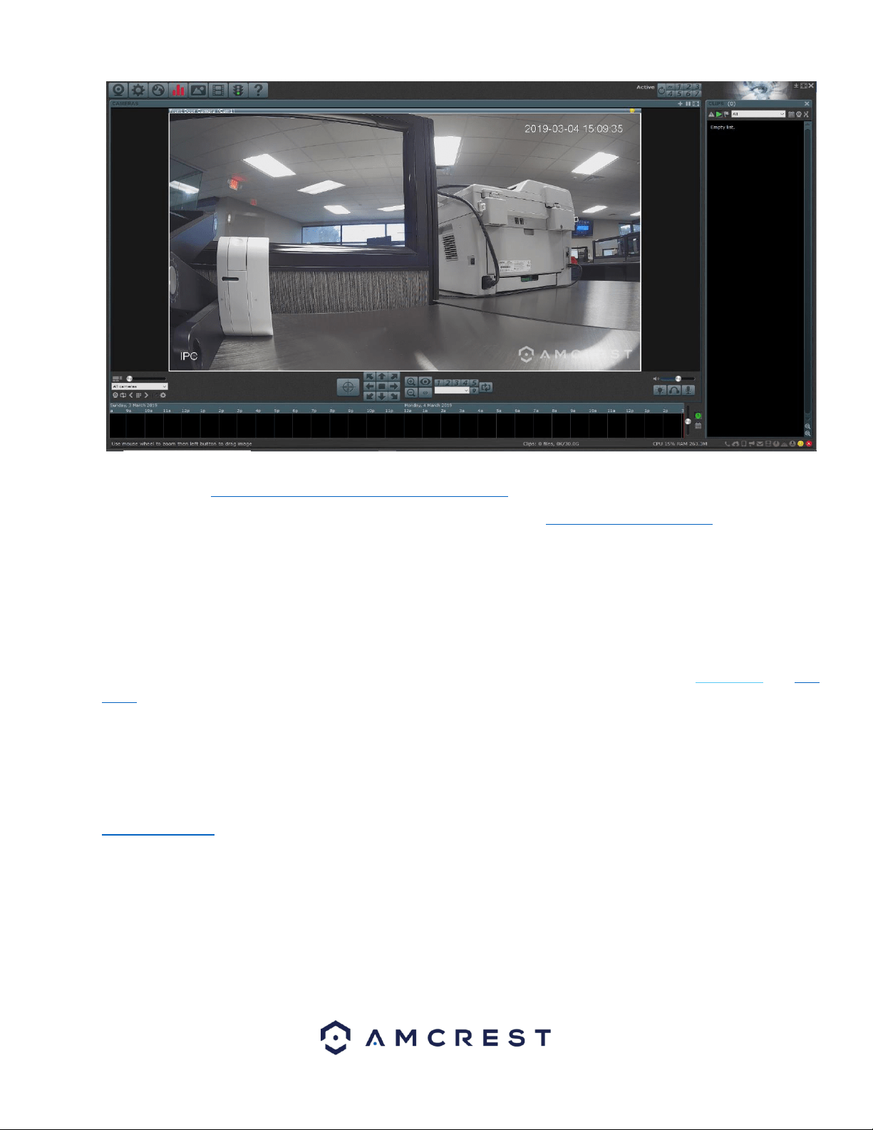
39
To view an informative video on how to add an Amcrest device into the Amcrest Blue Iris software, please view this
informative video: https://www.youtube.com/watch?v=RqcfLHANCd8
For more information on the features included in the Blue Iris software visit, http://blueirissoftware.com/
4.4.3. Web Operation
NPAPI plugins have been recently depreciated by most mainstream web browsers such as Google Chrome, Outlook, and
Firefox. Currently, our team is pursuing a solution to this, however, as a primary means of accessing the web user interface
for your Amcrest device in a web browser, we recommend using Internet Explorer. Other browser will also be functional
such as, the Amcrest Web View app for Google Chrome, a previously released version of Mozilla Firefox, such as Firefox
49.0.2, or Safari 11.
As an alternative, other secondary browsers will also be functional for the web user interface such as, SeaMonkey, and Pale
Moon web browsers. SeaMonkey is compatible with Windows and Mac and is free to use, Pale Moon is only compatible
with Windows and Linux systems. Conversely, both browsers will require the use of a plugin like other web browsers.
Note: Pale Moon users, please use the 32-bit version of the browser as the 64-bit version may be incompatible with our
plugins.
You can also use the Amcrest Cloud to access your device from your computer. Amcrest Cloud does not require the use of a
plugin to function and is compatible on most modern browsers. For more information on the Amcrest Cloud, visit
amcrest.com/cloud.
Web Access for Safari and Mac Users
Most current versions of Safari do not support NPAPI plugins. Certain browsers, such as Safari 11, may be compatible,
however, would require the user to revert from their current version of Safari to Safari 11. Amcrest has devised ways Mac
users can enjoy their Amcrest products on their computers without the hassle of dealing with plugins with software such as
Amcrest Blue Iris and Surveillance Pro.
Conversely, MacOS Mojave may be the last operating system to support 32-bit apps, such as, Amcrest Surveillance Pro. For
this reason, it is highly advised for Mac users to take advantage of such options as the Google Chrome Extension app,
40
Amcrest Blue Iris, Mozilla Firefox version 49.0.2., and SeaMonkey. Each of these methods of web-based access will be
covered in the sections provided.
How to Install SeaMonkey
SeaMonkey is a free and open-source internet browser that serves as an excellent means of implementing the plugins
required to access your device via a web browser. SeaMonkey is compatible for both Windows and Mac Operating
Systems. It is a continuation of the former Mozilla Application Suite and is based on the same source code which itself grew
out of Netscape Communicator and formed the base of Netscape 6 and Netscape 7.
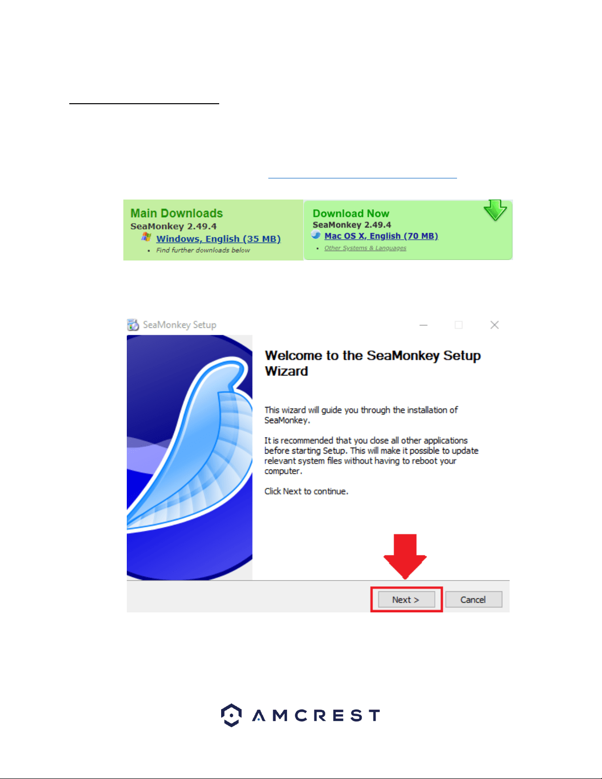
To download SeaMonkey on your computer, visit https://www.SeaMonkey-project.org/releases/ Select the download that
applies to your computer and begin the installation process.
Click on the downloaded SeaMonkey Setup file and run the setup wizard. For purposes of these instructions we will be using
Windows, however, the Mac setup process will be similar. Click Next to proceed.
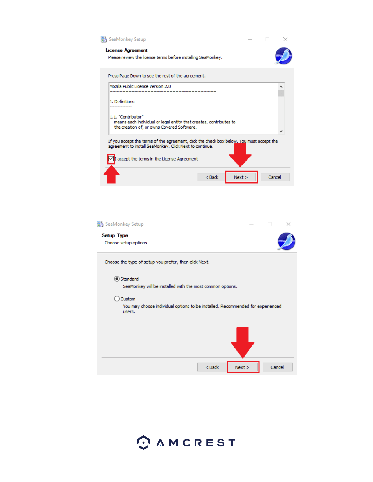
Please review the license terms before installing SeaMonkey. Read the license agreement carefully, and then to accept the
terms, click the checkbox next to the I accept the terms in the License Agreement checkbox. Click Next to continue.
41
Choose the type of setup you prefer. There are two types of setup, Standard and Custom. In this case, it is recommended to
run the standard setup since it is the most common. This is selected by default in the wizard. To continue, click the Next
button.
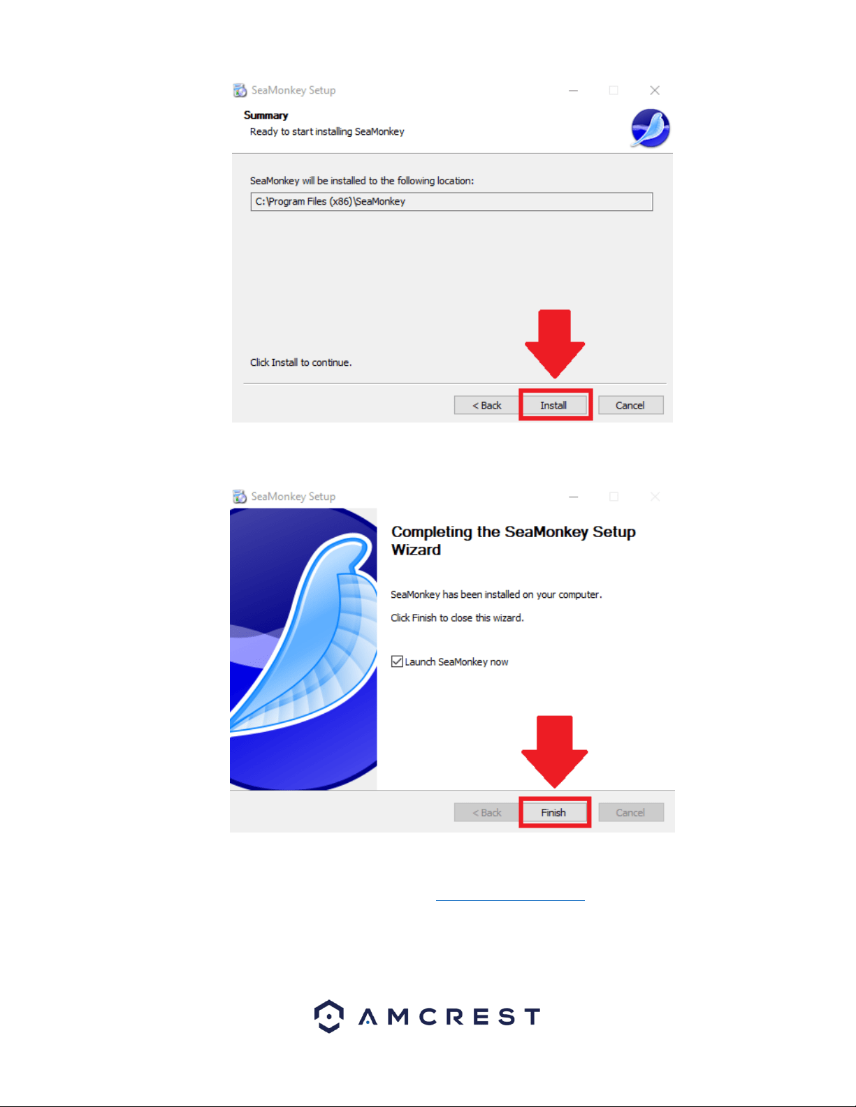
The wizard will then prompt you to install the software onto your computer. Click the Install button to install the browser.
42
Allow the browser to install on your computer. When it has finished installing click on Finish to launch the browser.
How To Access a Device Using SeaMonkey
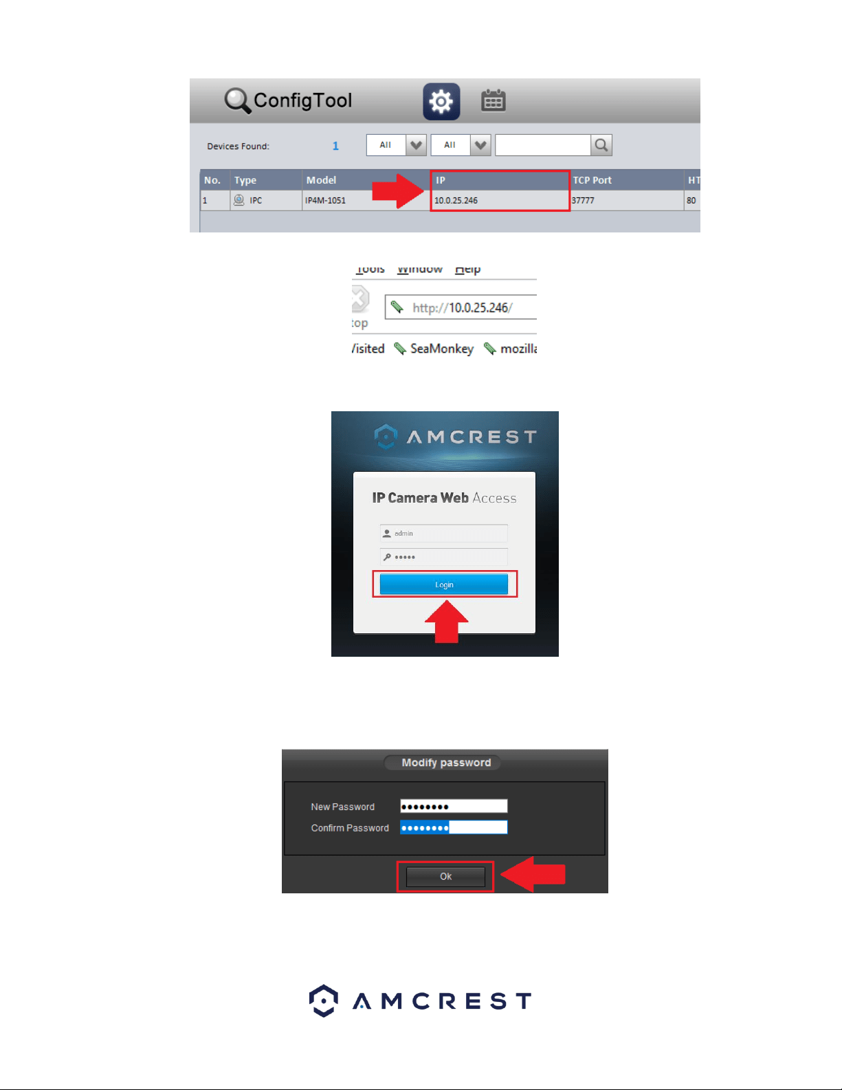
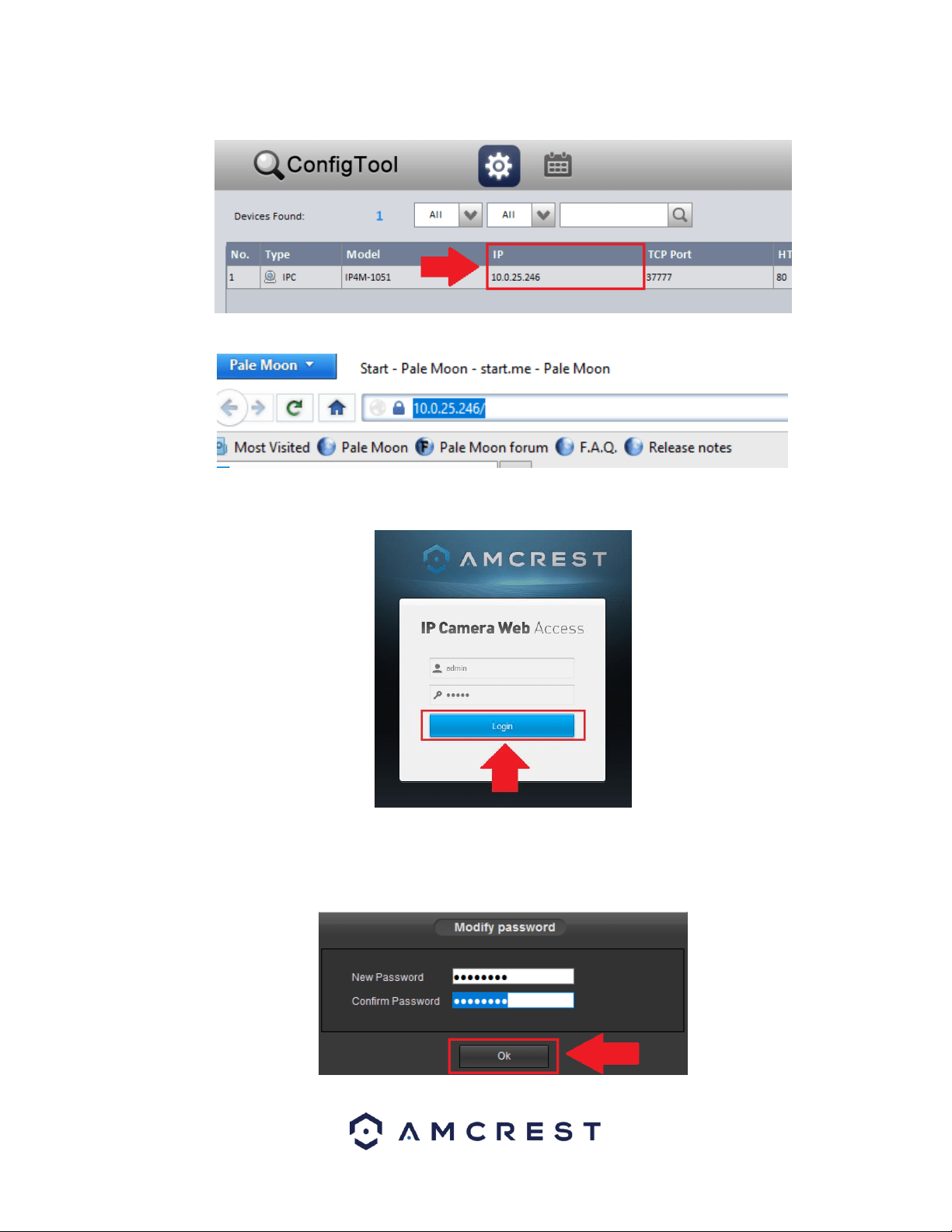
To access the web user interface, locate the IP address for your device using the Amcrest IP Config Tool. The Amcrest IP
Config Tool can be downloaded at the following web page: amcerest.com/downloads
In the All Downloads menu, click on IP Config Software to begin the free download. Once the download has completed
installing, locate the IP address associated with the device you would like to view in the browser.
43
Enter this IP address into the SeaMonkey web browser to load the web user interface.
In the web user interface, enter the login credentials for your device. If this is the first time accessing the device, the
username and password will both be admin. Click on Login.
If this is the first-time logging into your device, you will be prompted to modify the password for your device. To modify the
password, enter the new password you would like to use in the New Password field and confirm. The password used should
be between 8 and 32 characters long with a combination of letters and numbers. Click Ok when done to log into the web
user interface.
To view your device on the browser you will need to download the plugin. To download the plugin, click on the Please click
here to download and install the plugin prompt in the middle of the screen.
44
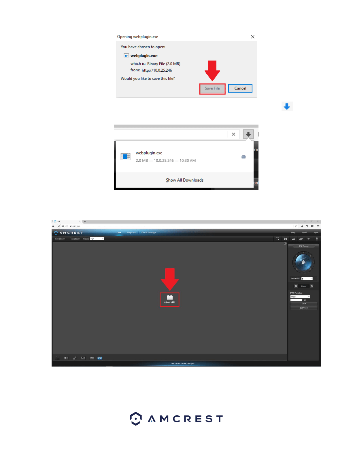
Click on Save File to being downloading the plugin and save the file to your computer.
The browsers Download Manager will appear, showing the plugin file that was just downloaded. Double click on the file in
the download manager to begin installing the plugin to the SeaMonkey web browser.
The browser will then show the live feed of your connected device in the web user interface.
45
For more information on the web user interface and the features it provides, please refer to the user manual for your
device. User manuals can be found at amcrest.com/support or on the original listing of your device.
Using Multiple Cameras in the Web UI
Due to chipset limitations with certain model Amcrest cameras, different plugins may be required when accessing your
camera on your computer.
This section is specifically geared towards customers who have 3MP and below cameras and are experiencing issues when
accessing a newer, 4MP and above camera, simultaneously with their old setup. Higher megapixel cameras will require the
use of a different plugin when accessing them on a web browser.
This is normal as most higher megapixel cameras require different internal hardware to function. Conversely, this may pose
a compatibility issue when accessing a lower megapixel camera in a web browser at the same time as the higher megapixel
camera since the higher megapixel camera's plugins will take precedence over the lower megapixel camera's plugin.
How To Install Pale Moon
Like SeaMonkey, Pale Moon is a free and open-source internet browser that serves as an excellent means of implementing
the plugins required to access your device via a web browser. Pale Moon is only compatible with Windows and Linux
operating systems however, a beta version is coming soon for Mac. The browser is a continuation of the former Mozilla
Application Suite and is based on the same source code which itself grew out of Netscape Communicator and formed the
base of Netscape 6 and Netscape 7.
To download Pale Moon on your computer, visit https://www.palemoon.org/download.shtml Select the download that
applies to your computer from the 32-bit downloads link section on the page and begin the installation process.
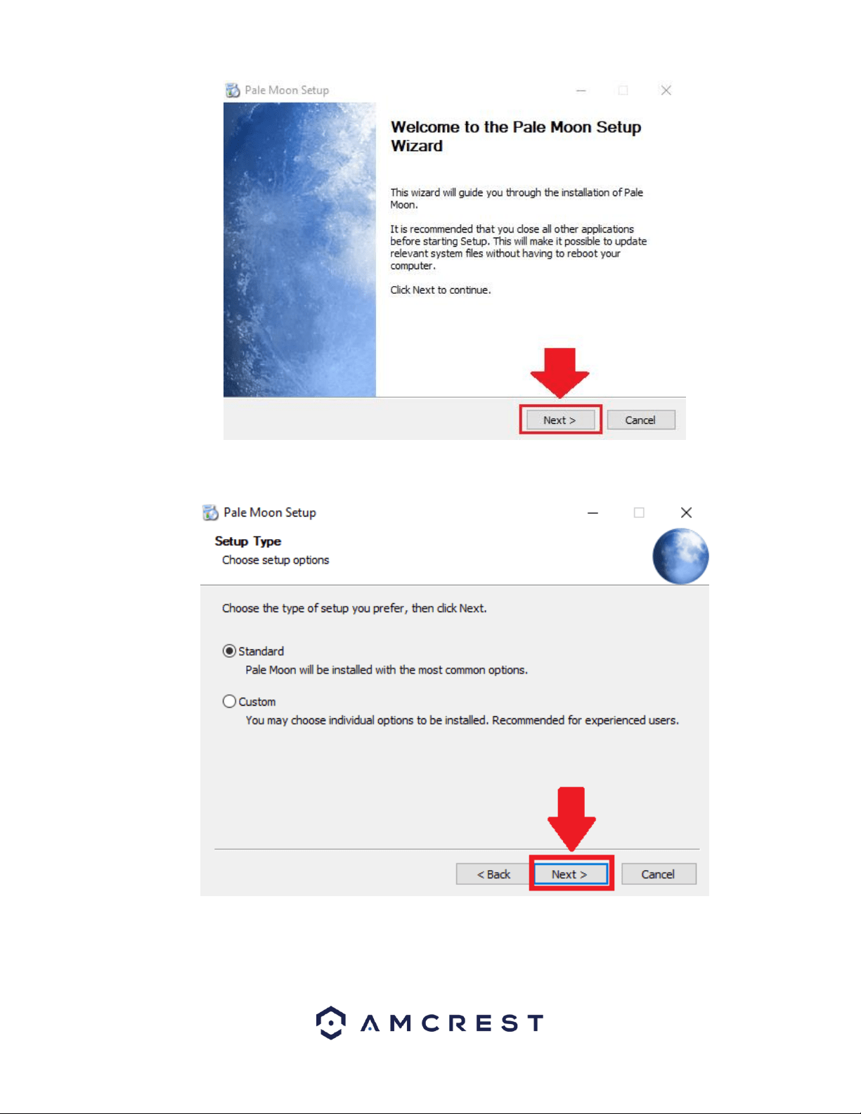
Click on the downloaded Pale Moon Setup file and run the setup wizard. For purposes of these instructions we will be using
Windows, however, other setup process will be similar. Click Run to proceed to the setup wizard. Click Next to begin.
46
Choose the type of setup you prefer. There are two types of setup, Standard and Custom. In this case, it is recommended to
run the standard setup since it is the most common. This is selected by default in the wizard. To continue, click the Next
button.
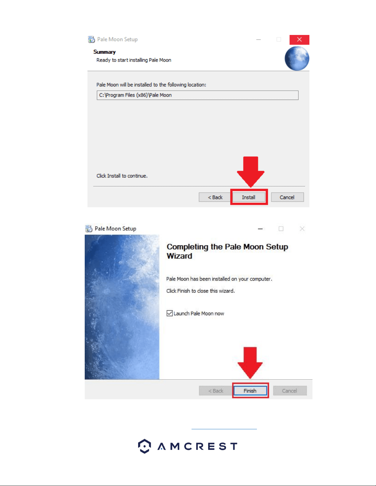
The wizard will then prompt you to install the software onto your computer. Click the Install button to install the browser.
47
Allow the browser to install on your computer. When it has finished installing click on Finish to launch the browser.
How To Access a Device Using Pale Moon
To access the web user interface, locate the IP address for your device using the Amcrest IP Config Tool. The Amcrest IP
Config Tool can be downloaded at the following web page: amcerest.com/downloads
48
In the All Downloads menu, click on IP Config Software to begin the free download. Once the download has completed
installing, locate the IP address associated with the device you would like to view in the browser.
Enter this IP address into the Pale Moon web browser to load the web user interface.
In the web user interface, enter the login credentials for your device. If this is the first time accessing the device, the
username and password will both be admin. Click on Login.
If this is the first-time logging into your device, you will be prompted to modify the password for your device. To modify the
password, enter the new password you would like to use in the New Password field and confirm. The password used should
be between 8 and 32 characters long with a combination of letters and numbers. Click Ok when done to log into the web
user interface.
49
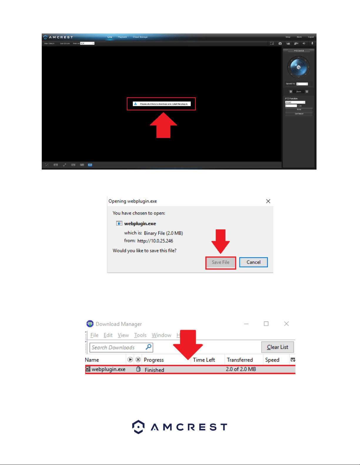
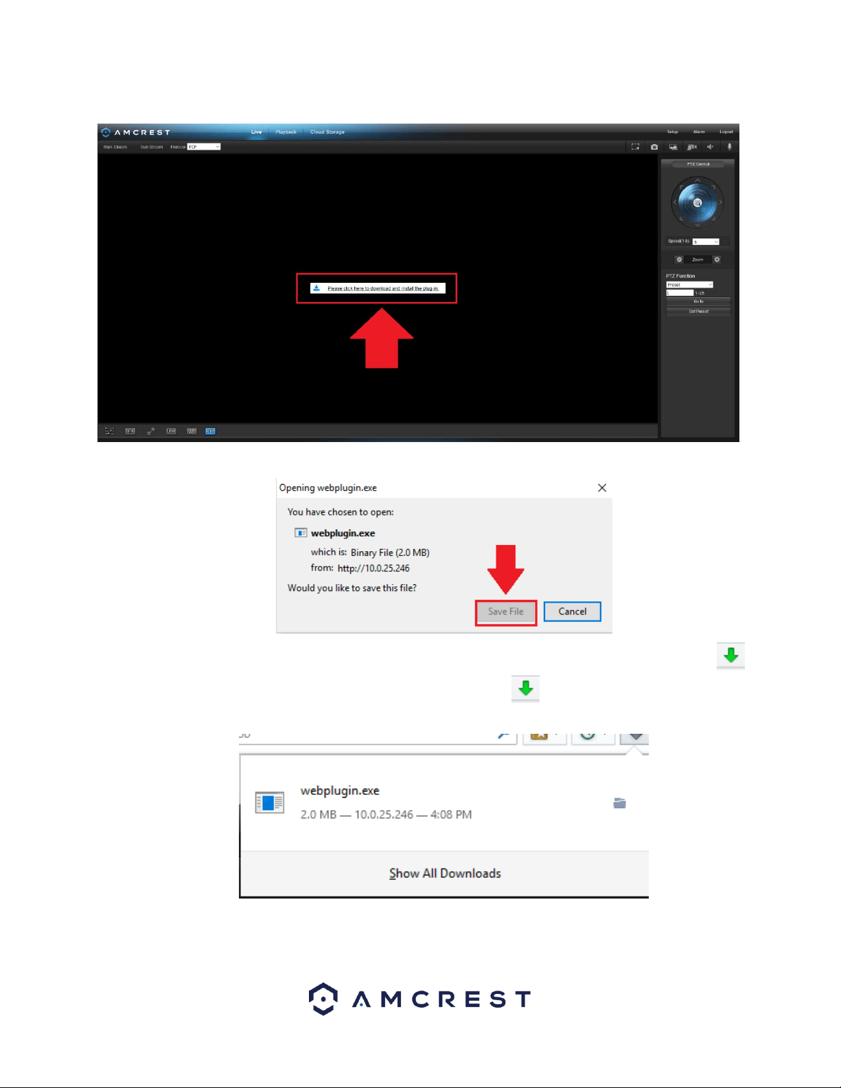
To view your device on the browser you will need to download the plugin. To download the plugin, click on the Please click
here to download and install the plugin prompt in the middle of the screen.
Click on Save File to being downloading the plugin and save the file to your computer.
The webplugin.exe will then be downloaded to the downloads folder and be shown in the Download Manager in the
upper right-hand corner of the browser. To launch the plugin, click on the and click on the webplugin.exe file in the
download manager.
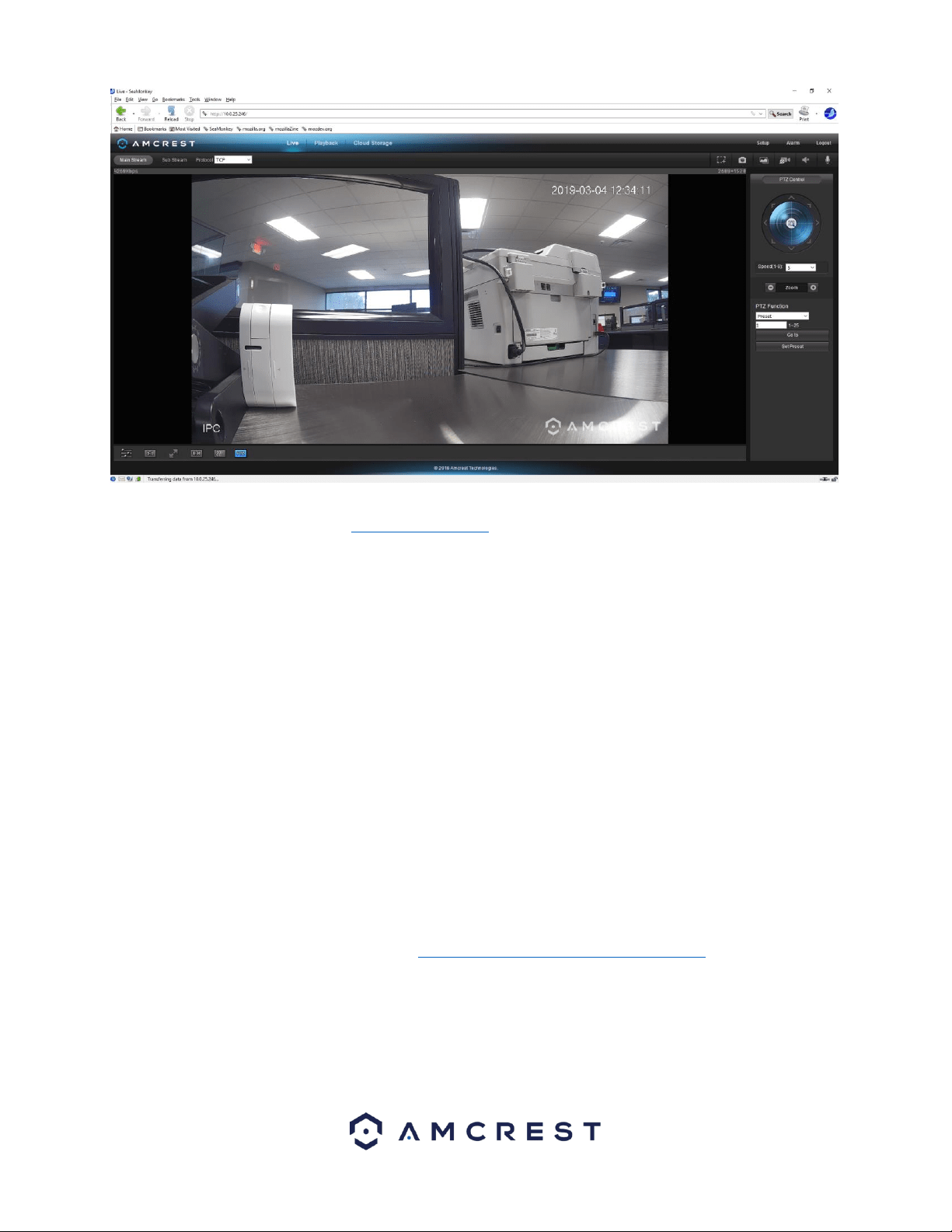
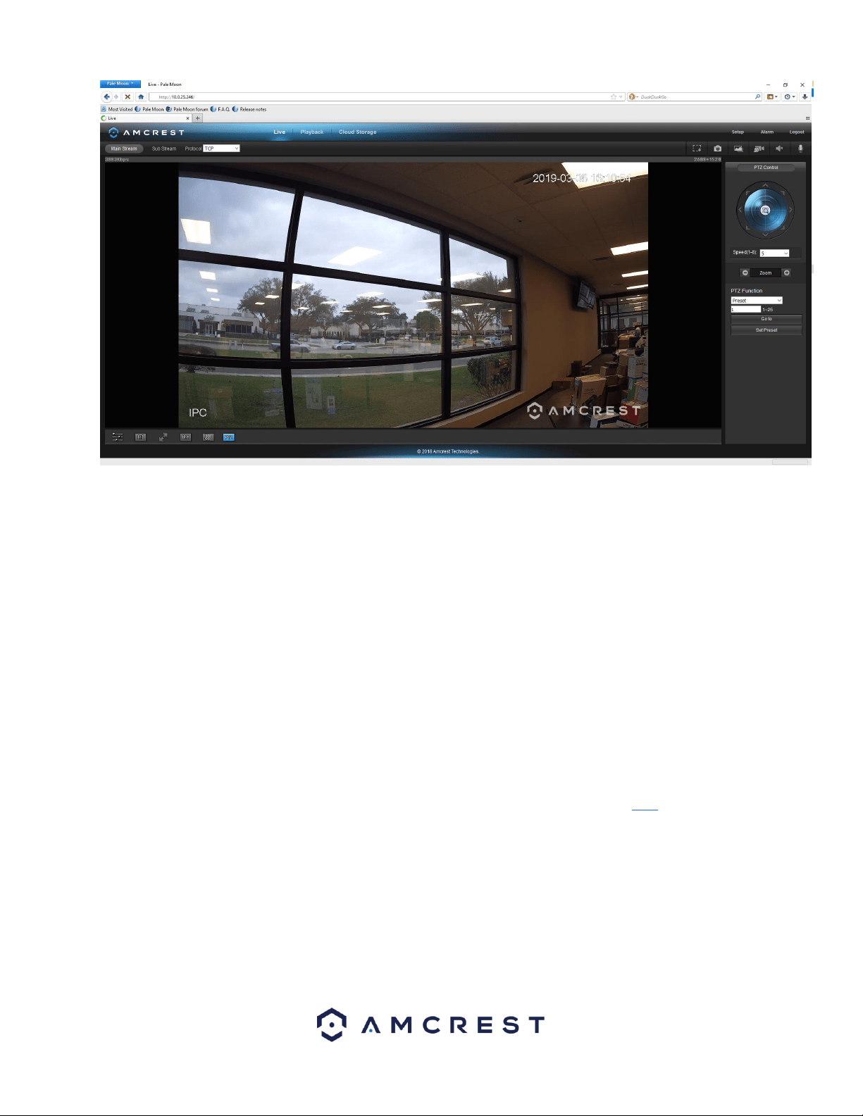
The browser will then show the live feed of your connected device in the web user interface.
50
Using Multiple Cameras in the Web UI
Due to chipset limitations with certain model Amcrest cameras, different plugins may be required when accessing your
camera on your computer.
This section is specifically geared towards customers who have 3MP and below cameras and are experiencing issues when
accessing a newer, 4MP and above camera, simultaneously with their old setup. Higher megapixel cameras will require the
use of a different plugin when accessing them on a web browser.
This is normal as most higher megapixel cameras require different internal hardware to function. Conversely, this may pose
a compatibility issue when accessing a lower megapixel camera in a web browser at the same time as the higher megapixel
camera since the higher megapixel camera's plugins will take precedence over the lower megapixel camera's plugin.
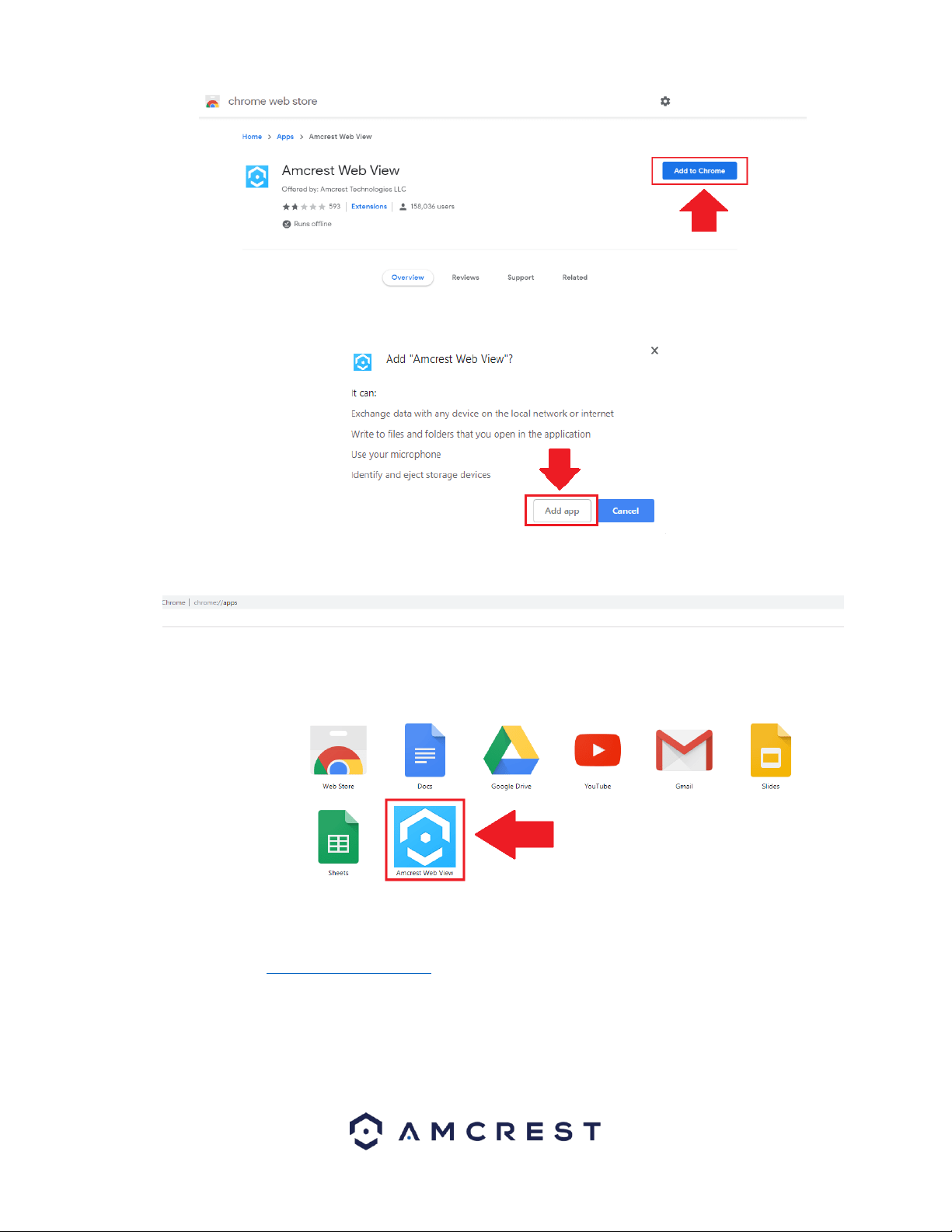
How To Access a Device Using the Google Chrome Extension
Web based access for Amcrest device can be utilized in Google Chrome using the Amcrest Web View Chrome App. This is an
app designed by Amcrest specifically for the use of accessing your device in Chrome without the use of a plugin and is
available in the Chrome web store. To add the Amcrest Web View app to your browser, click here.
Adding the Amcrest Web View App
In the Chrome Web Store, click on the Add to Chrome button to add the extension to your Chrome browser.
51
To confirm the addition of the Amcrest Web View app to your browser, click on the Add app option listed in the popup.
The app will begin to download to your Chrome app store. The Chrome app store can be accessed by typing the following
URL into your browser: chrome//apps Click on the Amcrest Web View to launch the app.
To access your device using the Google Chrome Extension please refer to the information provided below.
Locate the IP address for your device using the Amcrest IP Config Tool. The Amcrest IP Config Tool can be downloaded at
the following web page: amcerest.com/downloads
In the All Downloads menu, click on IP Config Software to begin the free download. Once the download has completed
installing, locate the IP address associated with the device you would like to view in the browser.
52
Enter this IP address into the Chrome web browser to load the web user interface.
In the web user interface, enter the login credentials for your device. If this is the first time accessing the device, the
username and password will both be admin. Click on Login.
If this is the first-time logging into your device, you will be prompted to modify the password for your device. To modify the
password, enter the new password you would like to use in the New Password field and confirm. The password used should
be between 8 and 32 characters long with a combination of letters and numbers. Click Ok when done to log into the web
user interface.
The app will then show the live feed of your connected device in the web user interface.
53
How to Access a Device Using Firefox
The latest update of Mozilla Firefox will be discontinuing the use of plugins which may cause issues with accessing the web
user interface for your device while using Firefox. The plugin will affect the ability to view and playback, however, setting
changes will still be available using this method on most devices.
We are currently working on a more permanent solution to the issue but currently, we recommend using a previous version
of Firefox such as Firefox 49.0.2. For more information on how to revert to Mozilla Firefox 49.0.2. refer to the instructions
provided below.
Reverting to FireFox 49.0.2.
To use the Firefox web browser with your device a previous version, such as 49.0.2. is recommended. You can download the
previous version of Firefox by clicking here. To revert to this version, click on the .exe file provided and then click “Run” to
begin downloading.
The file will then begin to extract the setup Wizard. Click Next to continue the process.
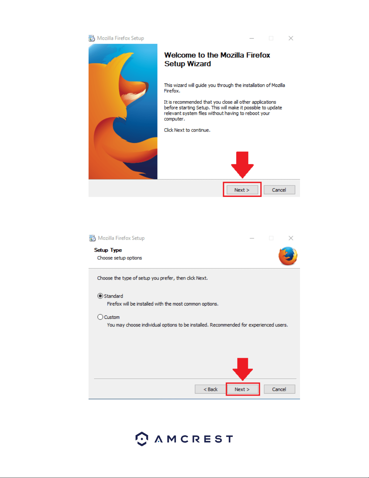
54
Choose the type of setup you prefer. There are two types of setup, Standard and Custom. In this case, it is recommended to
run the standard setup since it is the most common. This is selected by default in the wizard. To continue, click the Next
button.
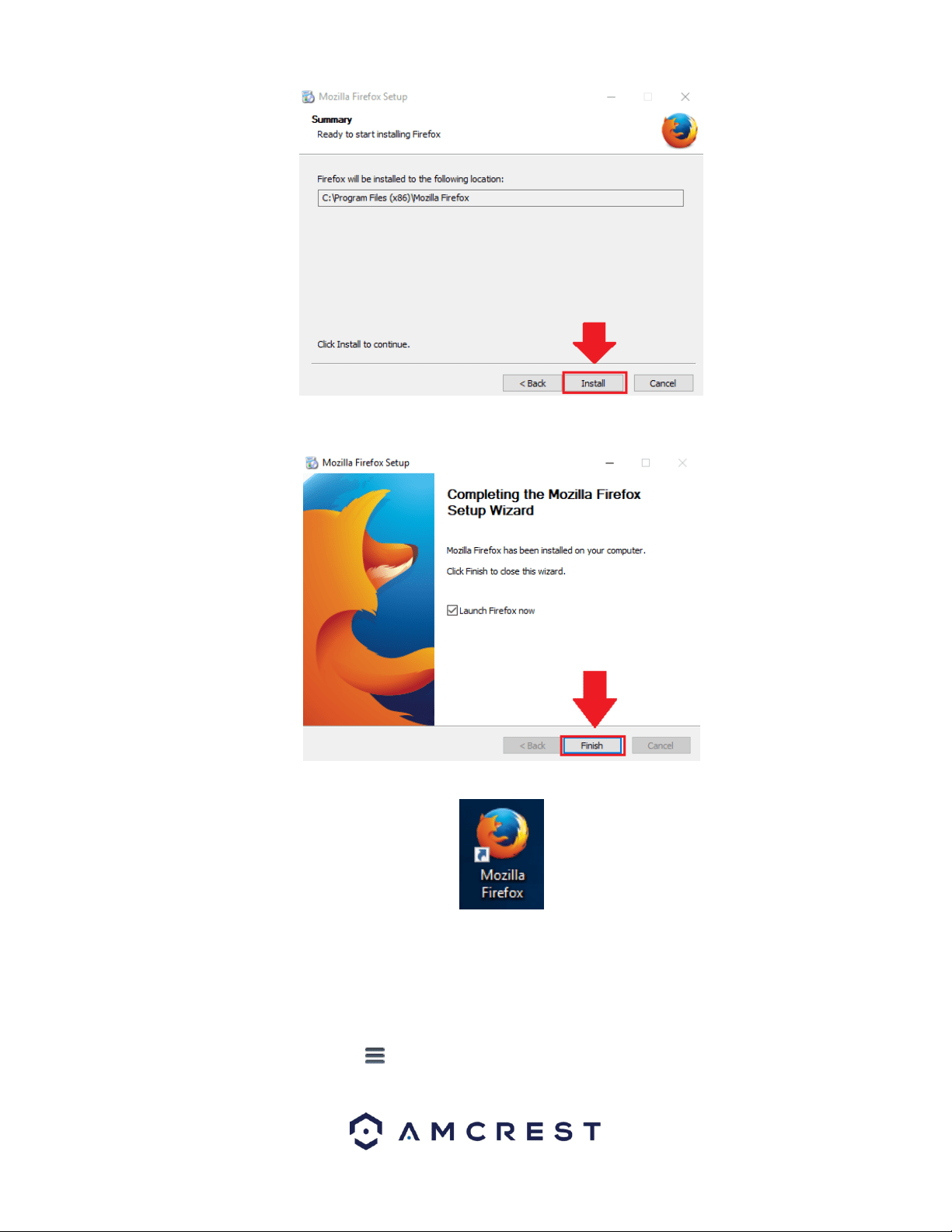
The wizard will then prompt you to install the software onto your computer. Click the Install button to install the browser.
55
When the installation is complete, click on the finish button to automatically launch the browser.
A shortcut icon will also be displayed on your desktop for quick access to the browser if necessary.
Preventing Automatic Updates
Once the browser has finished loading, it is recommended to make sure that no future automatic updates are applied to the
browser. If an automatic update were to occur, the browser will revert to the most current version of the FireFox web
browser which will prevent the use of plugins on your browser. To prevent automatic updates from occurring, please refer
to the following:
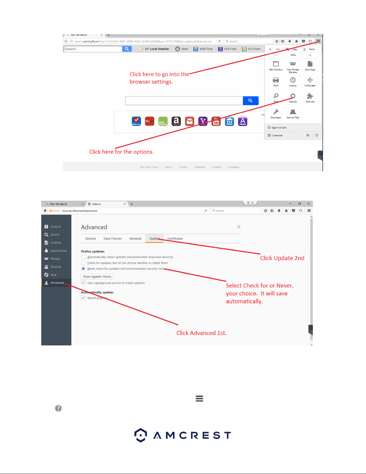
In the web browser, click on the settings menu located at the top of the screen. Then in the settings menu, click on the
Options icon.
56
In the options menu, click on Advanced and then click on the Update tab. In the update tab, select the Never check for
updates radio button. This will deactivate your browser from obtaining any future updates of the browser.
How to Access the Web User Interface Using Firefox
Before accessing your device using Mozilla Firefox, ensure you are using the correct version of Firefox. As discussed
previously, later versions of Firefox may prevent the use of plugins which are needed to access your device.
Verify the Correct Version of Firefox is Being Used
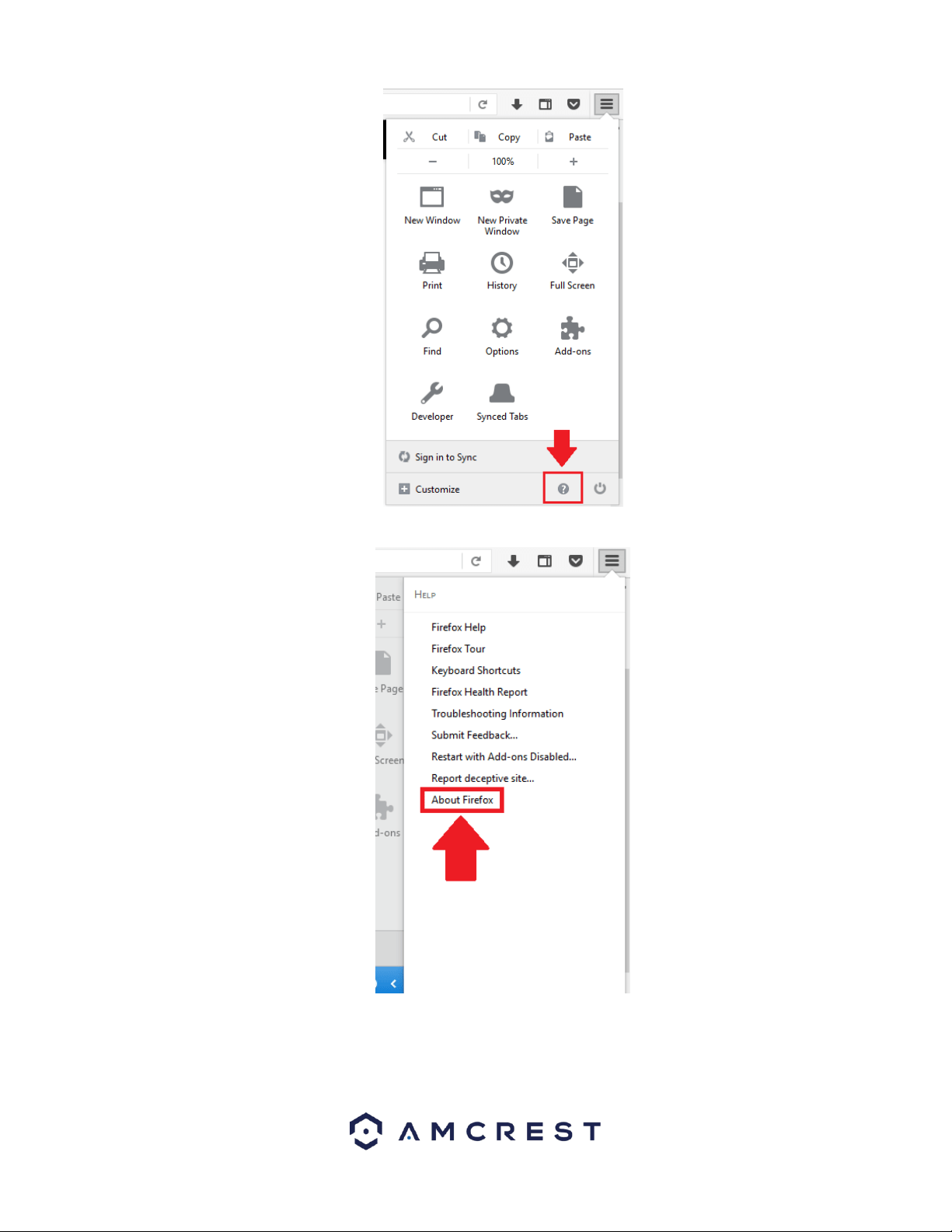
To verify the correct version is being used, click on the settings menu located at the top of your screen and click on the
help menu at the bottom of the settings menu
57
In the help menu, select About Firefox
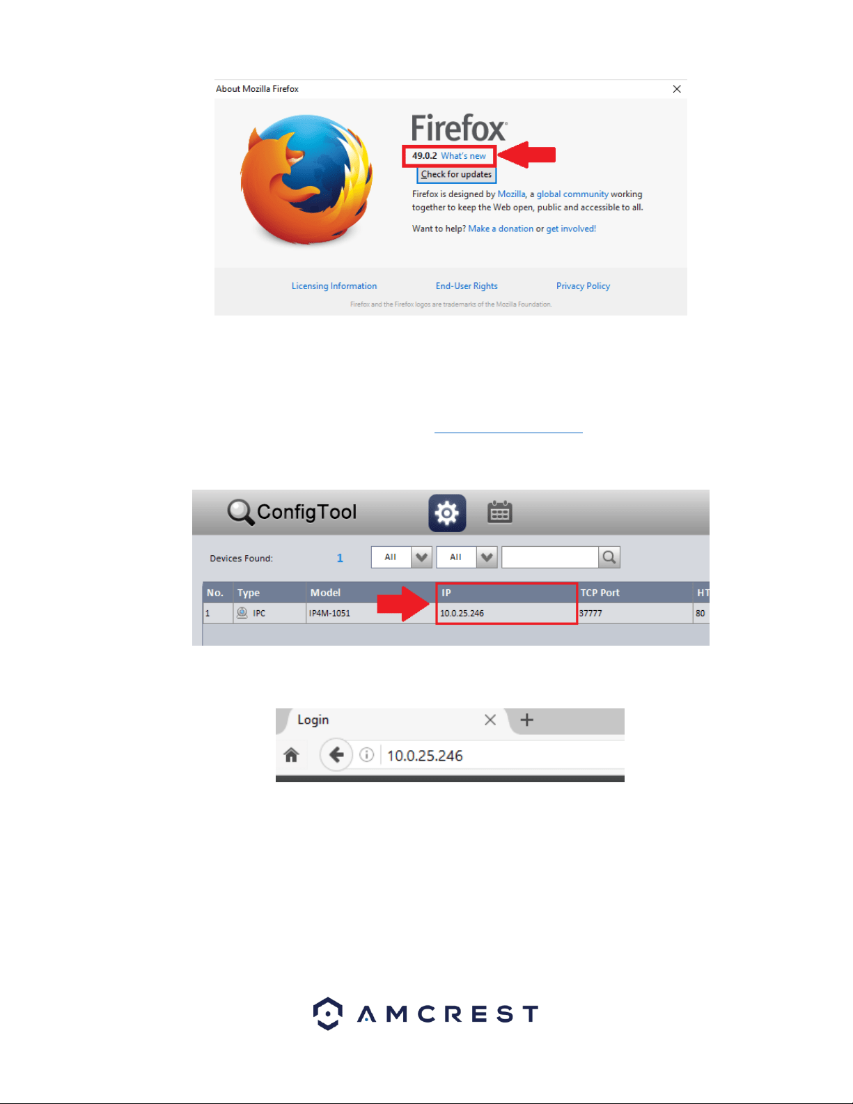
The version being used will be displayed in the About Mozilla Firefox menu as displayed in the image below.
58
It is recommended to use version 49.0.2. Do not click on Restart Firefox to Update. This will update the browser and cause
the plugins not to work on the browser.
Accessing the Web User Interface
To access the web user interface, locate the IP address for your device using the Amcrest IP Config Tool. The Amcrest IP
Config Tool can be downloaded at the following web page: amcerest.com/downloads
In the All Downloads menu, click on IP Config Software to begin the free download. Once the download has completed
installing, locate the IP address associated with the device you would like to view in the browser.
Enter this IP address into the Firefox web browser to load the web user interface.
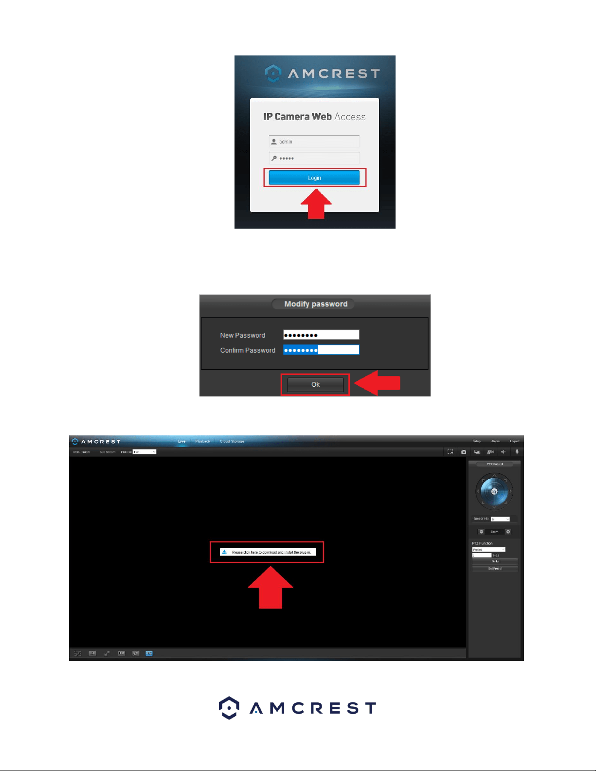
In the web user interface, enter the login credentials for your device. If this is the first time accessing the device, the
username and password will both be admin. Click on Login.
59
If this is the first-time logging into your device, you will be prompted to modify the password for your device. To modify the
password, enter the new password you would like to use in the New Password field and confirm. The password used should
be between 8 and 32 characters long with a combination of letters and numbers. Click Ok when done to log into the web
user interface.
To view your device on the browser you will need to download the plugin. To download the plugin, click on the Please click
here to download and install the plugin prompt in the middle of the screen.
Click on Save File to being downloading the plugin.
60
The webplugin.exe file will save to your downloads folder. To install the plugin, click on the downloads icon and click on
the webplugin.exe to install the plugin on your computer.
After the web plugin has been installed, close out of the browser completely and then reopen the browser. Type in the IP
address for your device into the browser and log into the web user interface with your device’s login credentials. Click on
the Activate MMX icon in the middle of the screen to activate the plugin.
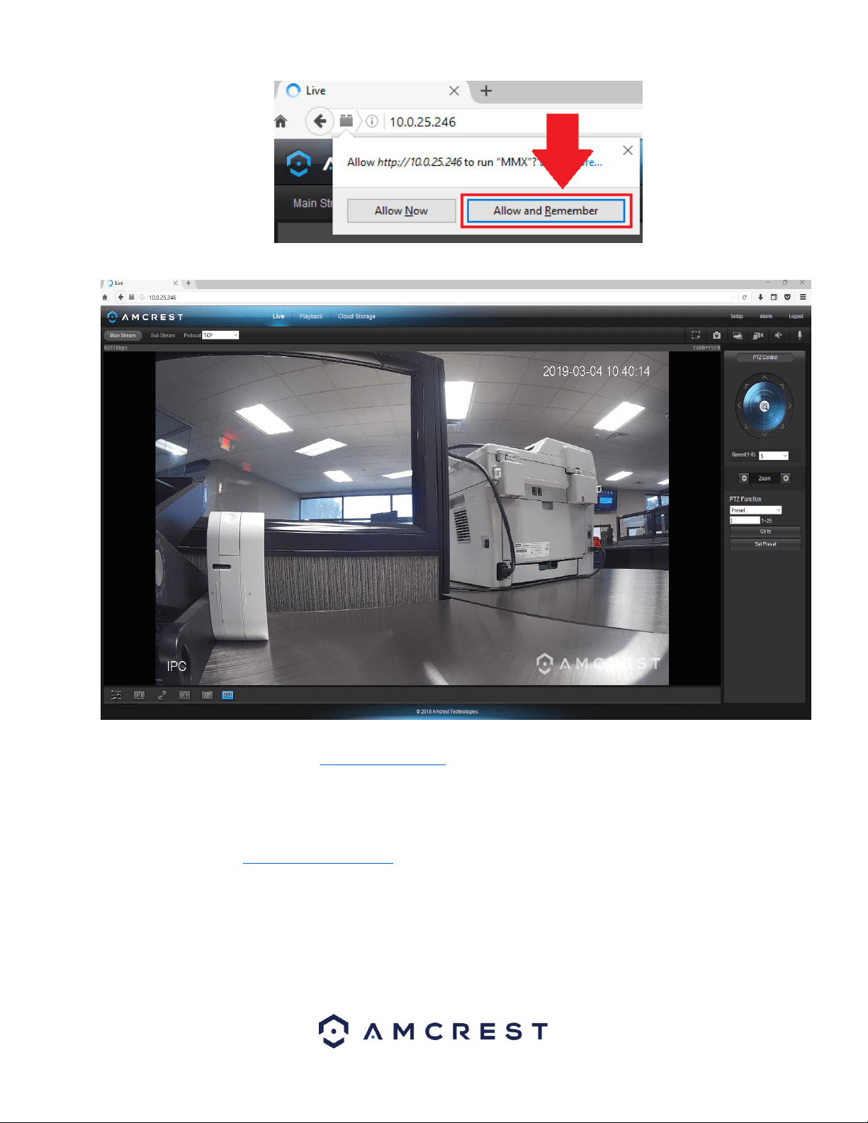
The browser will then need to run the MMX plugin. Click on Allow and Remember to allow the browser to run the MMX
plugin.
61
The browser will then show the live feed of your connected device in the web user interface.
For more information on the web user interface and the features it provides, please refer to the user manual for your
device. User manuals can be found at amcrest.com/support or on the original listing of your device.
How To Access the Web User Interface Using Internet Explorer
To access your device using the Google Chrome Extension please refer to the information provided below.
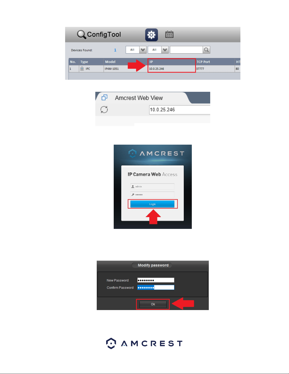
Locate the IP address for your device using the Amcrest IP Config Tool. The Amcrest IP Config Tool can be downloaded at
the following web page: amcerest.com/downloads
In the All Downloads menu, click on IP Config Software to begin the free download. Once the download has completed
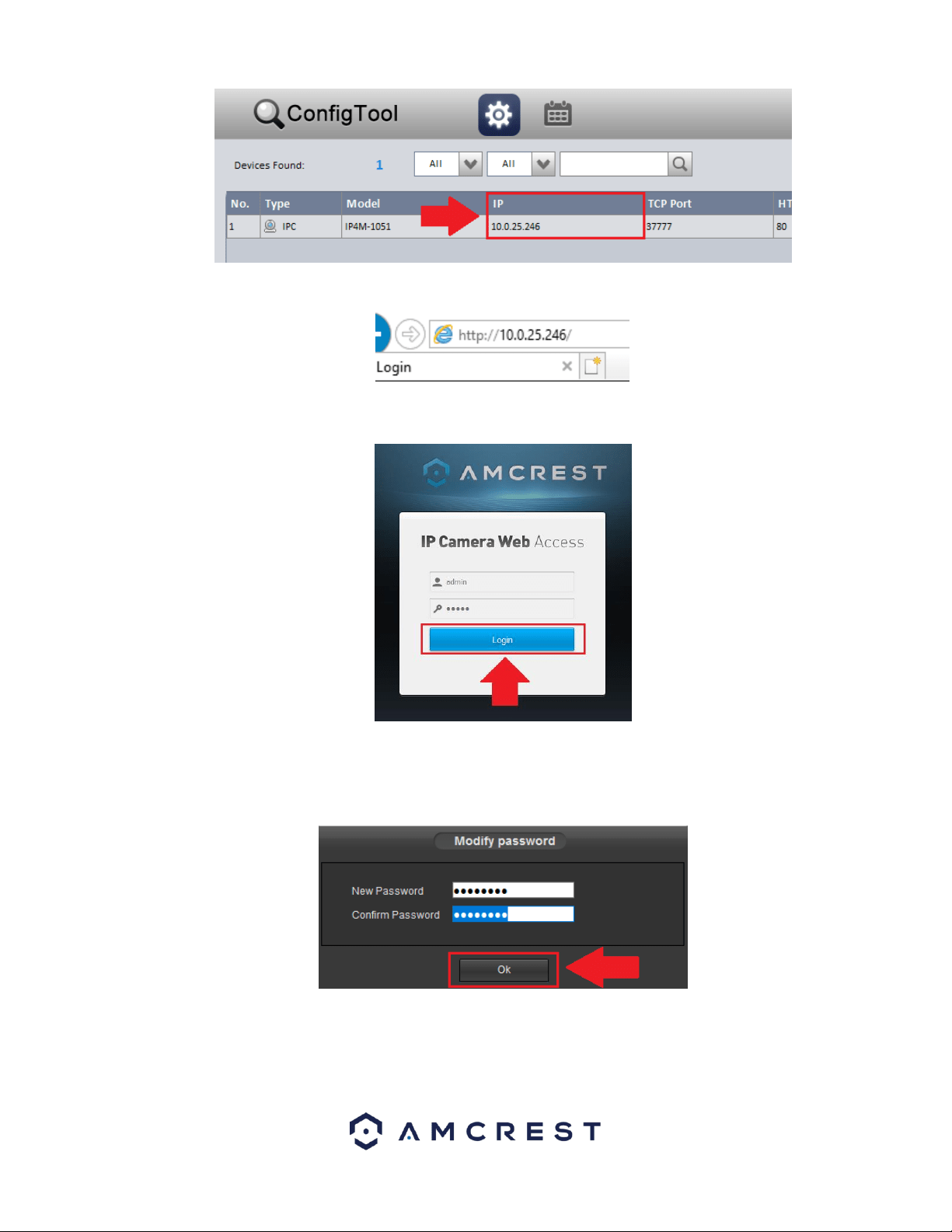
installing, locate the IP address associated with the device you would like to view in the browser.
62
Enter this IP address into the Internet Explorer browser and press enter to load the web user interface.
In the web user interface, enter the login credentials for your device. If this is the first time accessing the device, the
username and password will both be admin. Click on Login.
If this is the first-time logging into your device, you will be prompted to modify the password for your device. To modify the
password, enter the new password you would like to use in the New Password field and confirm. The password used should
be between 8 and 32 characters long with a combination of letters and numbers. Click Ok when done to log into the web
user interface.
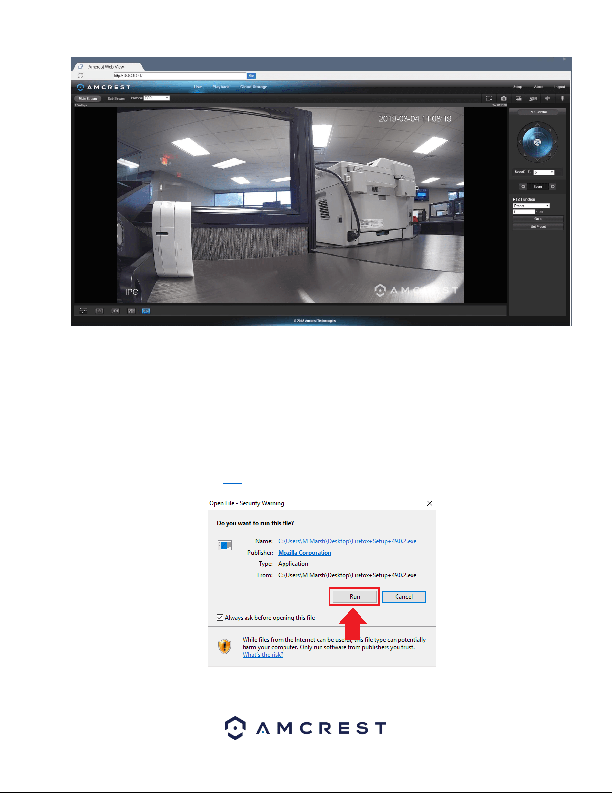
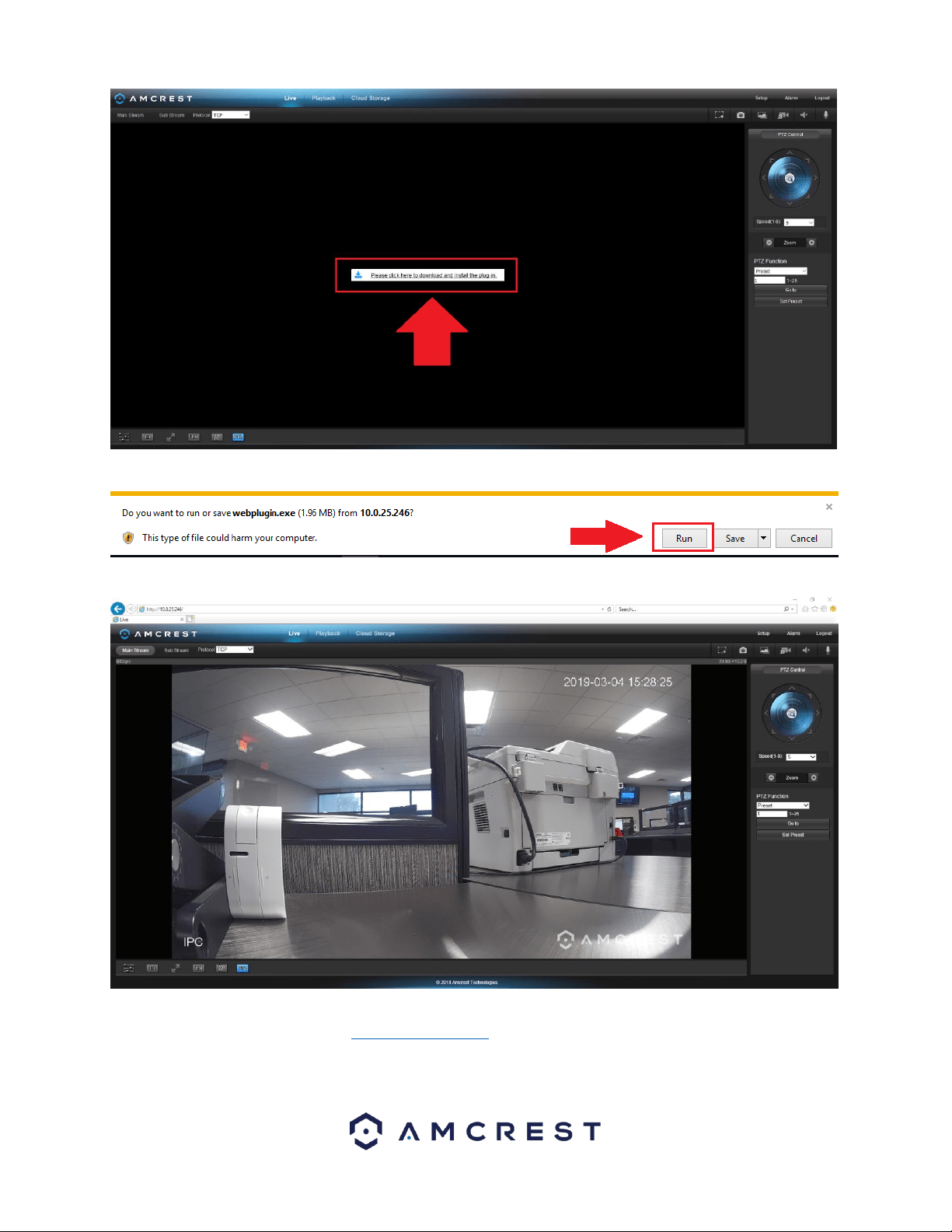
To view your device on the browser you will need to download the plugin. To download the plugin, click on the Please click
here to download and install the plugin prompt in the middle of the screen.
63
Click Run to download the plugin.
The browser will then show the live feed of your connected device in the web user interface.
For more information on the web user interface and the features it provides, please refer to the user manual for your
device. User manuals can be found at amcrest.com/support or on the original listing of your device.
4.4.4. Remote Web Access Setup
There are two main methods for setting up remote access: UPnP/DDNS, and Port Forwarding.

64
UPnP/DDNS Remote Web Access Setup
Using Universal Plug and Play (UPnP) and Dynamic Domain Name Server (DDNS) functionality is the easiest way to setup
stable remote access. For this method, your router should support the uPnP networking protocol and the protocol should
be enabled. Please refer to your router manufacturer’s documentation to learn how to enable uPnP on your router.
Below is a step-by-step walkthrough that details how to setup Amcrest cameras for Remote Web Access using UPnP and
DDNS:
1. Login to your camera’s web interface, open the main menu then go to Setup -> Network.
2. Using the left-hand menu, go to the Connection menu, and write down the HTTP port. It is recommended to ensure the port
number is at least 5 digits long to prevent any port conflicts. If need be, change the port to a 5-digit number that is less than
65535, note the number down, and click save before proceeding to the next step.
3. The system will prompt you to reset the camera. Click OK and wait for the camera to restart.
4. Restarting the camera may cause the device to use another IP address. Use the included IP Config tool to find the IP address
as detailed previously in this document.
5. Login to your camera, open the main menu then go to Setup -> Network.
6. Click the Connections menu item on the left-hand menu and ensure that the HTTP port has changed.
7. Click the DDNS menu item on the left-hand menu, pick Amcrest DDNS from the drop down box, click the checkbox next to
Server Type, and then click the Save button on the bottom right.
8. To set a custom DDNS name, fill out the Domain Name field and click Save.
9. Write down the entire Domain Name field, including the white text that says .AmcrestDDNS.com
10. Click the UPnP menu item on the left-hand menu and click the enable checkbox at the top.
11. While in the UPnP menu, double click the HTTP port, and change both the internal and external HTTP ports to match the
number that was used in step 2.
12. Uncheck the last 4 checkboxes in the PAT table on the UPnP menu.
13. Click apply, then exit this menu to go back to the main menu, then re-enter the UPnP menu, and ensure the UPnP status
says, “Mapping Successful”.
14. Open a web browser and enter in the DDNS domain name address from step 9, enter in a colon, then type the port number
from step 4 on to the end.
a. For example, if the DDNS domain name is http://abc123456789.AmcrestDDNS.com and your HTTP Port is 33333, the URL
would be http://abc123456789.AmcrestDDNS.com:33333
15. The browser may prompt you to install a plugin. Click install to download the plugin, and then click on the plugin installation
file to install the plugin.
16. If the browser prompts you to allow the plugin to work on the computer, hit Allow to ensure the plugin can run successfully.
17. Enter in login details into the username and password fields and click login.
If the process above is not working, please contact Amcrest Support via one of the following options:
Visit http://amcrest.com/contacts and use the email form.
Call Amcrest Support using one of the following numbers
Toll Free: (888) 212-7538
International Callers (Outside of US): +1-713-893-8956
USA: (888) 212-7538
Canada: 437-888-0177
UK: 203-769-2757
Email Amcrest Customer Support [email protected]m

65
Port Forwarding Remote Web Access Setup
Port Forwarding is an alternative method to setting up remote access for Amcrest cameras. This method should only be
used if the UPnP/DDNS Remote Access method did not work.
Below is a step-by-step walkthrough that details how to setup the camera for Remote Web Access using Port Forwarding:
1. Login to your camera, open the main menu then go to Setup -> Network.
2. Open the TCP/IP settings screen.
3. By default, the camera has the mode set to DHCP. Ensure that DHCP is selected. The IP Address, Subnet Mask, Default
Gateway, Preferred DNS, and Alternate DNS should all be 0s if DHCP is selected.
4. Click Save to save these settings. This should now open the main menu.
5. From the main menu, go to Setup -> Network.
6. On the TCP/IP settings screen, the IP Address, Subnet Mask, Default Gateway, Preferred DNS, and Alternate DNS should all
be populated.
7. Click the radio button next to Static, to change the mode to Static.
8. Write down the IP Address that is currently in the IP address field.
9. Click the Save button.
10. Using the left hand menu, go to the Connection menu, and write down the TCP, UDP, and HTTP port number. It is
recommended to ensure that these port numbers are at least 5 digits long to prevent any port conflicts. If need be, change
each of these port numbers to a 5-digit number that is less than 65535, note the numbers down, and click save before
proceeding to the next step.
11. Go to http://www.canyouseeme.org/ and check to ensure each of the port numbers specified in step 10 is open.
12. Write down the manufacturer name, brand, and model name for the router that the camera is connected to, and then
proceed to http://www.portforward.com on your web browser.
13. Open the port forwarding guide section on the left-hand side menu.
14. Find the router brand name in the list and click it.
15. Find the router model number and click it.
16. Click the Default Guide link near the middle of the page.
17. This guide will help you take the step necessary to port forward on the router. Follow these steps, and then return to the
camera.
18. Login to your camera, open the main menu then go to Setup -> Network.
19. Click the DDNS menu item on the left-hand menu, pick AMCRESTDDNS from the drop-down box, click the checkbox next to
Server Type, and then click the Save button on the bottom right.
20. To set a custom DDNS name, fill out the Domain Name field and click Save.
21. Write down the entire Domain Name field, including the white text that says .AmcrestDDNS.com
22. Open a web browser and enter in the DDNS domain name address from step 21, enter in a colon, then type the HTTP port
number from step 10 on to the end.
For example, if the DDNS domain name is http://abc123456789.AmcrestDDNS.com and your HTTP Port is 33333, the URL
would be http://abc123456789.AmcrestDDNS.com:33333
23. Enter in login details into the username and password fields and click login.
If the process above is not working, please contact Amcrest Support via one of the following options:
Visit http://amcrest.com/contacts and use the email form
Call Amcrest Support using one of the following numbers
Toll Free: (888) 212-7538
International Callers (Outside of US): +1-713-893-8956
USA: (888) 212-7538
Canada: 437-888- 0177

66
UK: 203-769-2757
Email Amcrest Customer Support [email protected]m
4.5 Amcrest Cloud Desktop Setup
Amcrest cameras can sync with Amcrest Cloud; a service that stores recorded video streams to
enable long-term storage. Amcrest Cloud also allows the user to easily find and download recorded
video for playback from any internet connected PC or Mac computer.
For more information on how to setup your camera on Amcrest Cloud on the web, visit
amcrest.com/cloudwebsetup or follow the steps provided below:
1. Connect the camera to power and wait 30 seconds for the camera to start-up and initialize.
2. Using a web browser on your PC or Mac, visit www.amcrest.com/cloud and register for a cloud
account. Once registered, click the “Add Camera” button. Select “Amcrest”, give the camera a
name, and enter the camera’s SN (located on the bottom of the camera), then click “Next”.
3. On the settings page, you can adjust optional preferences for your camera. Once settings have
been adjusted, click “Finish”. Your camera is now successfully set up for cloud access and
storage.
4. View your camera live or watch recorded clips using the menu button on the top of the page.
You can also use the Amcrest Cloud app on iOS and Android to add more cameras, play
recordings, and view your camera live, from anywhere. For more information visit
amcrest.com/support
5. For additional assistance, please contact us at www.amcrest.com or give us a call at 1-888-212-
7538. Step by step video tutorials available at http://www.amcrest.com/videos
4.6 Web Access Setup (AmcrestView.com)
1. Connect the camera to power and wait 30 seconds for the camera to start-up and initialize.
2. Using Internet Explorer or Safari, go to www.AmcrestView.com and register an account.
You will be required to activate your account by e-mail (double-check your spam folder).
3. Once activated, download and install the plugin for your web browser. The installation of
the plugin will require all web browsers to close.
4. Log in to your account. To add a camera, click the “Add Device” button. Give the camera a
name, enter the UID (found on the bottom of your camera), then enter the login details for
the camera. The default username and password for the camera is admin.
5. Once added, the camera should appear in the device list. Click the icon next to the
camera’s UID to open the live viewing and playback interface.
6. The device is now successfully setup for live viewing and playback!
For additional assistance, please contact us at www.amcrest.com or give us a call at 1-888-212-7538. Step by step video
tutorials available at www.amcrest.com/videos
5 Operation and Interface
This section of the manual details the camera’s interface, as well as all the operations the camera can perform.
As previously stated, to access the web user interface for your device, it is recommended to use the free Amcrest IP Config
tool. The Amcrest IP Config tool can be found by visiting, amcrest.com/downloads.
Amcrest IP Config Tool
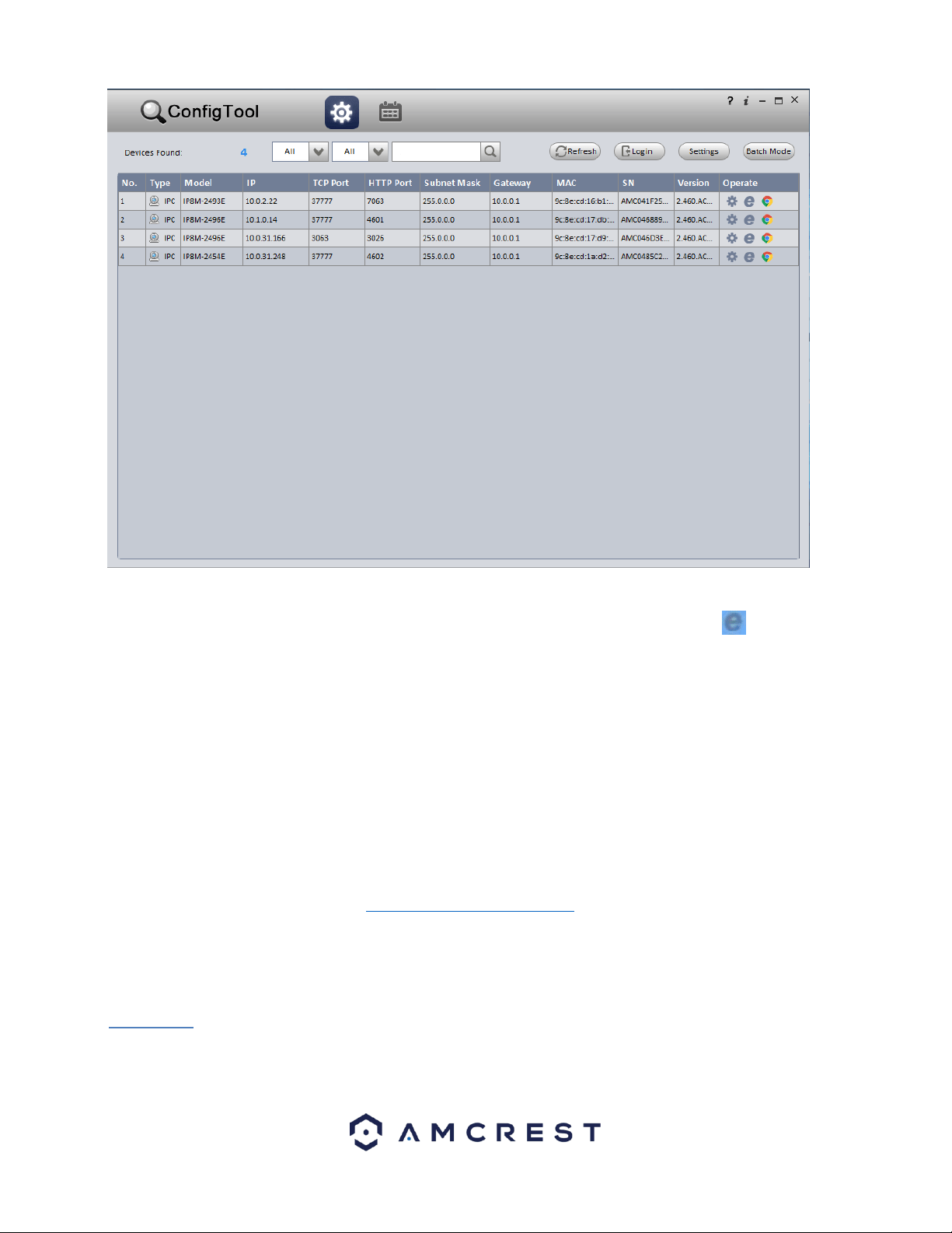
67
After launching the IP Config tool, click the Refresh button to bring up the cameras on the network.
Double click the camera’s line item to login and connect to the camera. Once logged in, click the
icon to open the camera’s interface in a web browser.
Log in to the camera using your login credentials (default username and password are both
“admin”). If this is your first-time logging into the camera, you will be prompted to change your
password. Please select a password that is at least 8 characters long, and one that uses a
combination of uppercase letters, lowercase letters, and numbers.
When opening the camera’s interface, the browser may prompt you to install a plugin. The plugins
are necessary for using the camera’s interface. Click install to download the plugin, and then click on
the plugin installation file to install the plugin. If the browser prompts you to allow the plugin to
work on the computer, hit Allow to ensure the plugin can run successfully.
The camera is now successfully set up for live viewing!
For additional assistance, please contact us at www.amcrest.com or give us a call at 1-888-212-7538.
Step by step video tutorials available at http://www.amcrest.com/videos
The main interface of the camera contains 6 major tabs on the top of the screen. By default, the interface opens on the Live
tab.
5.1. Live
This section of the manual details the camera’s interface, as well as all the operations the camera can perform.
The live view tab allows the user to see a live video feed from the camera. The live view tab has four main sections:
68
Section 1: This bar allows the user to select which stream type and which protocol they want to choose.
Section 2: The functions bar allows the user to perform different camera functions while in live mode. See the table below
for an explanation of the different functions available:
Button
Function Name
Function Description
Optical/Digital Zoom
Click this button to activate the zone selection function. This allows the user to
use the mouse to select a zone to zoom in on.
Snapshot
Click this button to take a screenshot of the live feed. The picture is saved at
the path specified in Setup -> Camera -> Video -> Path.
Triple Snapshot
Click this button to take 1 screenshot per second for 3 seconds. The pictures
are saved at the path specified in Setup -> Camera -> Video ->
Path.
Manual Record
Click this button to manually record video. The video is saved at the path
specified in Setup -> Camera -> Video -> Path.
Section 3: This bar allows the user to change video settings for the live playback screen. See the below table for an
explanation of the video settings:
Button
Function Name
Function Description
Image Adjustment
This button opens the image adjustment toolbar, which allows the user to
adjust brightness, contrast, saturation, and hue for the live feed’s picture.
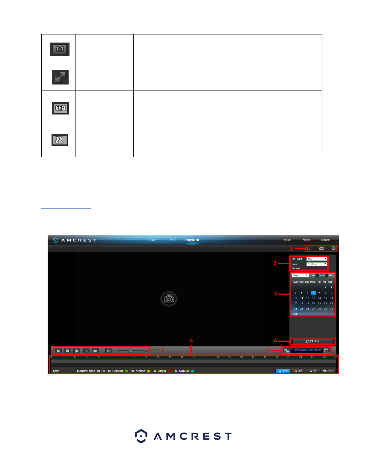
69
Adapt/Original Size
This button allows the user to switch between displaying the original size of
the stream in its set resolution, or to adapt to the size of the monitor
display the feed is being viewed on.
Full Screen
This button allows the user to make the live feed go into full screen mode.
Double click the mouse or click the ESC button to exit full screen mode.
Width/Height Ratio
This button allows the user to change the width/height ratio for the live
feed. The options are Original and Adaptive. Original uses the aspect ratio
of the stream’s set resolution, and adaptive fits the feed to the aspect
ratio of the monitor display the feed is being viewed on.
Stream Fluency
This button allows the user to change the stream fluency. There are 3
options. Realtime reduces delay and decreases fluency, and Fluency has a
larger delay, but the video stream becomes more fluid.
Section 4: This section of the Live tab shows the picture that the camera is broadcasting. The bitrate is shown in the top left
corner, the native resolution is shown in the top right corner, the time stamp is shown below the native resolution, and the
camera type is shown in the bottom left corner.
5.2 Playback
The Playback tab allows the user to playback the camera’s recorded video. Below is a screenshot of the Playback tab:
This is the interface for the playback menu. There are 7 main sections:
1. Quick Actions: This panel allows the user to zoom in on playback footage, take a snapshot of the playback footage, or open
the help menu.
2. File Menu: This panel allows the user to select a file type and data source.
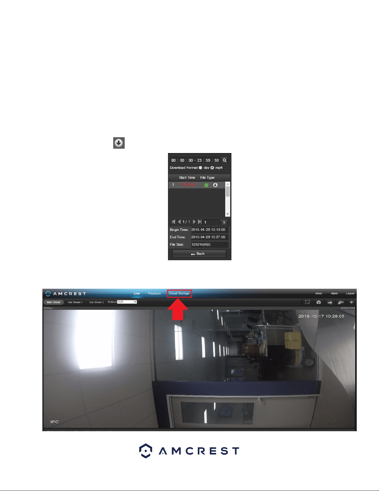
70
3. Calendar: This panel allows the user to pick a date that they would like to playback video from. When a date has recorded
footage available, it’s green. The current date is blue, unless it has recorded footage, then it’s a lighter green.
4. File List: This button opens a file list of all recorded video for a specific date range. From here, the user can download these
videos to their PC.
5. Trim Panel: This panel allows the user to trim playback video for download. By specifying time stamps, the user can trim
down.
6. Recorded Video Panel: This panel allows the user to specify what type of video they would like to playback and it also allows
the user to select where to start playback from. The buttons on the bottom right allow the user to select a zoom level.
7. Playback Bar: This panel allows the user to control playback. It also allows the user to control playback speed, and playback
volume.
Clicking the File List opens the following screen on the sidebar:
This allows the user to select files for download. Select the files by clicking the checkbox next to each file, and then click
to download the files to the PC.
5.3. Cloud Storage
The Cloud Storage tab allows the user quick access to the Amcrest Cloud website.
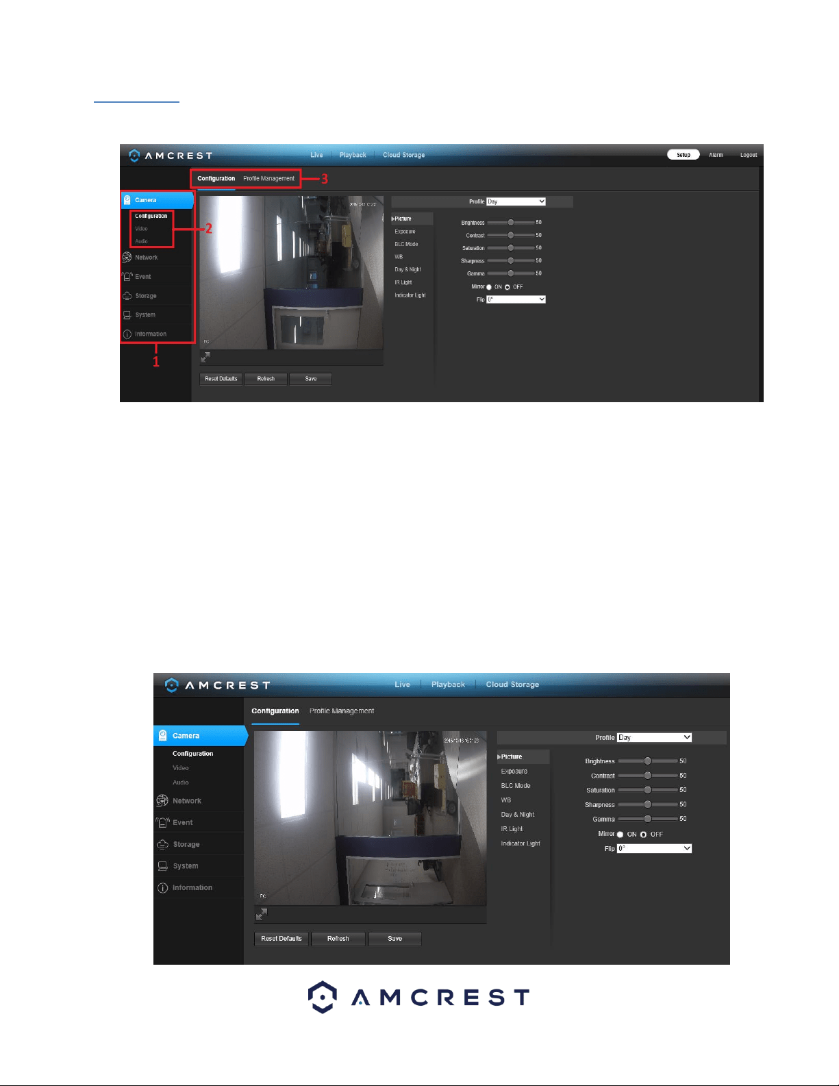
71
5.4 Setup
The Setup tab allows the user to change different camera settings. Below is a screenshot of the setup tab:
There are 3 main sections to note in the Setup tab:
1. Menu Bar: The menu bar is composed of menu sections, which when clicked display any menu items that fall under their
category.
2. Menu Items: These menu items each open a different menu that allows the user to change specific settings for the camera.
3. Menu Tab: These tabs open menu options for certain menu items.
5.4.1. Camera
This menu section allows the user to change different camera settings for video, audio, and to manage image profiles.
5.4.1.1 Configuration
This menu allows the user to configure image profiles for normal, day, and night usage. Below is a screenshot that shows the
Configuration tab in the Configuration menu item:

72
Below is an explanation for each of the fields on the Configuration tab in the Configuration menu item:
5.4.1.1.1. Picture
• Profile: This dropdown box allows the user to select which profile to modify. The 3 options are Day, Night, and Normal.
• Brightness: This slider is used to adjust playback and recorded video window brightness. The value ranges from 0 to 100. The
default value is 50. The larger the number, the brighter the video is. When you input the value here, the bright section and
the dark section of the video will be adjusted accordingly. You can use this function when the whole video is too dark or too
bright. Please note the video may become hazy if the value is too high. The recommended value ranges from 40 to 60.
• Contrast: This slider is used to adjust playback and recorded video window contrast. The value ranges from 0 to 100. The
default value is 50. The larger the number is, the higher the contrast is. You can use this function when the whole video
brightness is OK but the contrast is not correct. Please note the video may become hazy if the value is too low. If this value is
too high, the dark section may lack brightness while the bright section may over expose. The recommended value ranges
from 40 to 60.
• Saturation: This slider is used to adjust playback and recorded video window saturation. The value ranges from 0 to 100. The
default value is 50. The larger the number, the stronger the color is. This value has no effect on the general brightness of the
whole video. The video color may become too strong if the value is too high. For the grey part of the video, distortion may
occur if the white balance is not accurate. Please note the video may not be clear if the value is too low. The recommended
value ranges from 40 to 60.
• Sharpness: This slider is used to adjust the sharpness of the video. The value ranges from 0 to 100. The larger the value is,
the clearer the edges are and vice versa. Note: The higher the value, the higher likelihood of picture noise occurring. The
default value is 50 and the recommended value ranges from 40 to 60.
• Gamma: This slider is used to adjust the gamma of the video. The larger the number, the brighter the video is.
The default value is 50 and the recommended value ranges from 40 to 60.
• Mirror: This radio button allows the user to turn the mirroring feature on or off. Turning mirroring on will mirror the picture.
• Flip: This dropdown box allows the user to flip the video feed picture. Flipping the picture is recommended only if the
camera is mounted upside down.
Note: Due to specific limitations cameras 4MP and above will not be able to perform image flips in 90 or 270 degree
rotations.
5.4.1.1.2. Exposure
This dropdown box allows the user to select the exposure type for the video feed. The options are Auto, Low Noise, Low
Motion Blur, and Manual. When low noise is selected, an additional option to specify a gain range appears below this box.
When low motion blur is selected, an additional option to specify shutter speed appears below this box. When manual is
selected, additional options to specify a shutter speed and a gain range appear below this box.
Below is a screenshot of the exposure menu:
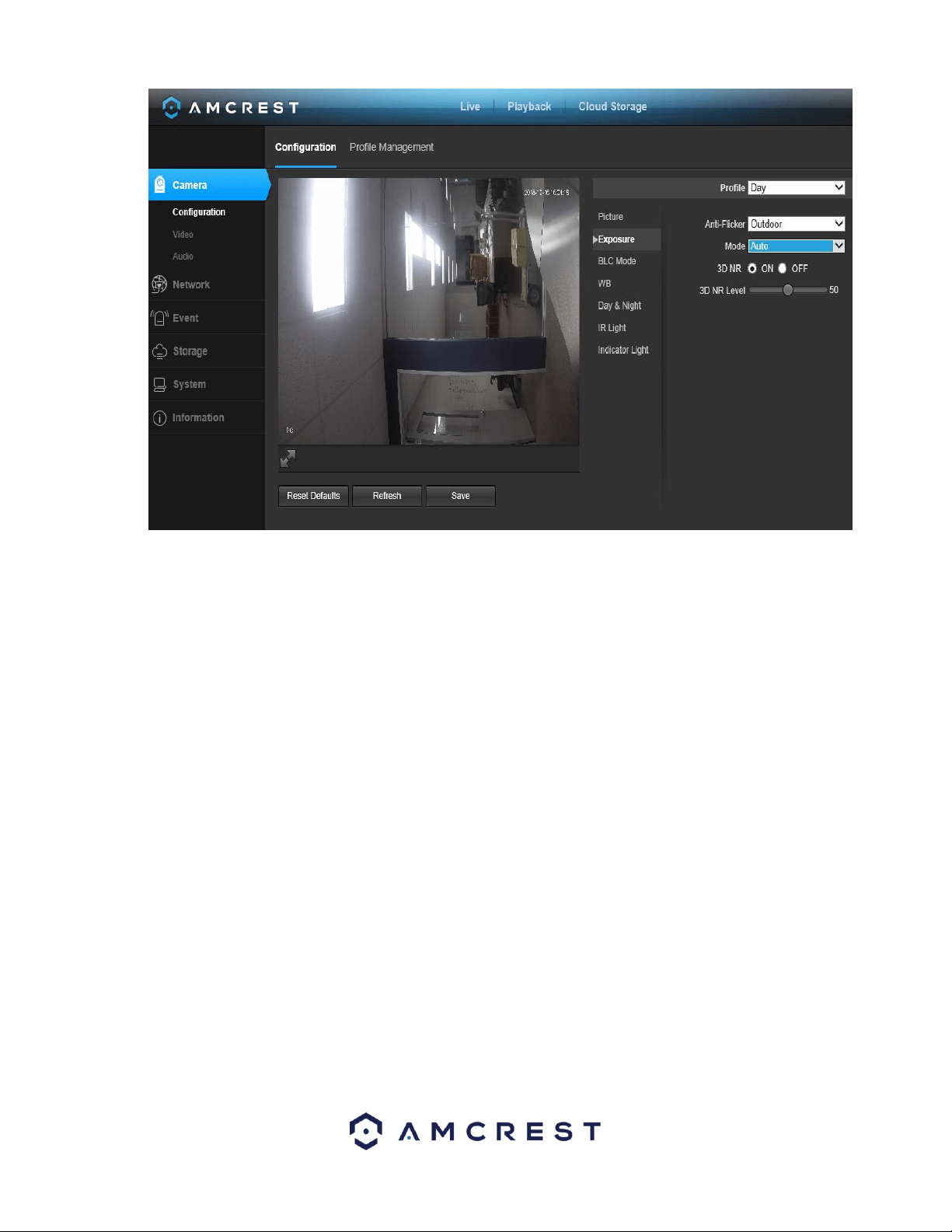
73
• Profile: This dropdown box allows the user to select which profile to modify. The 3 options are Day, Night, and Normal.
• Anti-Flicker: These radio buttons allow the user to select what type of anti-flicker technology should be used for the video
feed. The three options are 50 Hz, 60 Hz, and Outdoor. The desired option should offset any flickering effect caused by the
electrical current used in the specific area.
• Mode: This dropdown menu allows the user to modify certain exposure settings related to the device such as, gain priority,
shutter priority or setting a manual gain setting.
▪ Gain Priority - This setting will maximize the gain for the ideal exposure. Low Noise Basically turns up the ISO to the best
setting without sacrificing exposure timing.
▪ Shutter Priority - This setting will maximize the fastest shutter speed and will sacrifice the gain in return.
▪ Manual - This setting lets you select your shutter speed and have the gain adjust automatically. Selecting customized range
will let you both the shutter speed an adjust the gain manually.
• 3D NR: This radio button allows the user to turn the 3D Noise Reduction feature on or off.
• 3D NR Level: This slider allows the user to specify the 3D Noise Reduction level. The value ranges from 1-100.
To reset to default settings, click the Reset Defaults button. To refresh the screen, click on Refresh. To save the settings, click
the Save button.
5.4.1.1.3. BLC Mode
This dropdown box allows the user to select Back Light Compensation. The values are Off, BLC (Auto), WDR, and HLC. This
feature should only be used in black lit environments. Below is a screenshot of this menu:
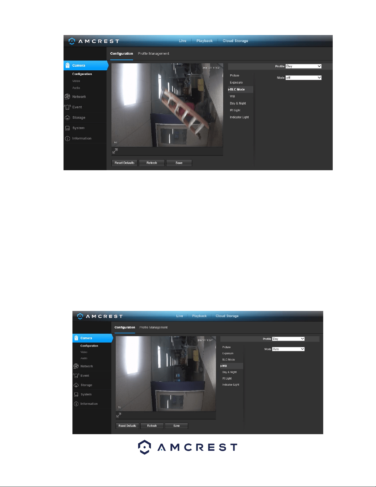
74
• BLC: backlight compensation: Default will use the whole image to balance the lighting settings, and Customized will allow
you to balance the lighting settings from the target area.
• WDR: Wide Dynamic Range makes multiple scans of a scene to provide one balanced and unwashed image that is clear for
the user.
• HLC: Highlight compensation is a feature that came out of necessity due to overexposure from strong light sources like
headlights or spotlights.
To reset to default settings, click the Reset Defaults button. To refresh the screen, click on Refresh. To save the settings, click
the Save button.
5.4.1.1.4. WB
This dropdown box allows the user to select the white balance for the video feed. The different options are Auto, Sunny,
Night, Outdoor, and Customized. Selecting customized opens a menu that allows the user to set specific red or blue values.
Below is a screenshot of this menu:
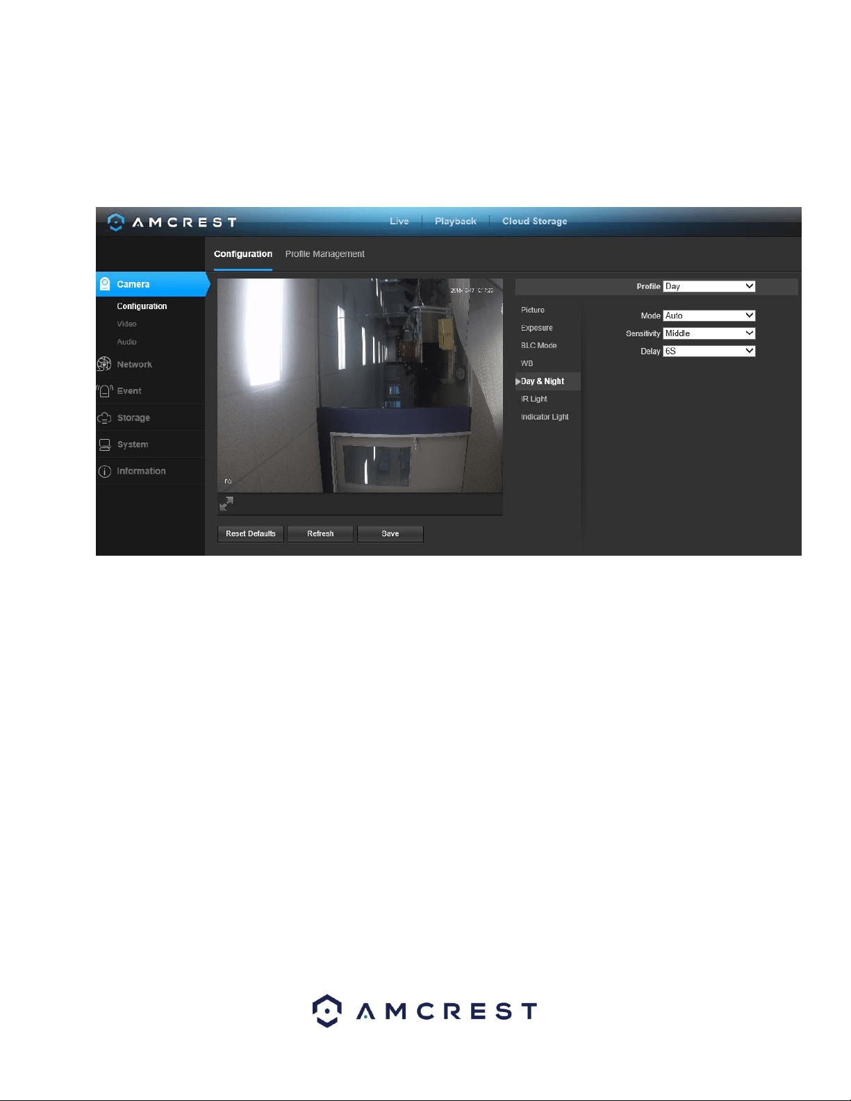
75
To reset to default settings, click the Reset Defaults button. To refresh the screen, click on Refresh. To save the settings, click
the Save button.
5.4.1.5. Day & Night
Used to determine when black and white mode is turned on in a dark environment. Below is a screenshot of this menu:
• Color - always represents picture in color, does not use IR or black and white mode. Performs poorly in dimly lit areas unless
you are using the Starlight series cameras.
• Auto - Uses D&N Sensitivity setting to change between color mode and infrared and black and white mode.
• Black & White - Always sets picture to black and white, however when illumination is too dark it switches on IR mode.
• Sensitivity: This option allows the user to change the Day/Night Sensitivity of the camera. The three options are Low,
Middle, and High. The higher the sensitivity, the quicker the camera will change into another mode depending on the light
levels.
• D&N Delay: This dropdown box allows the user to set a delay in seconds for how long it takes to switch between Day and
Night modes. The values range from 2 seconds to 10 seconds.
To reset to default settings, click the Reset Defaults button. To refresh the screen, click on Refresh. To save the settings, click
the Save button.
5.4.1.6. IR Light
This menu allows the user to select whether the IR lights for night vision are on or off for the selected profile. Below is a
screenshot of this menu:
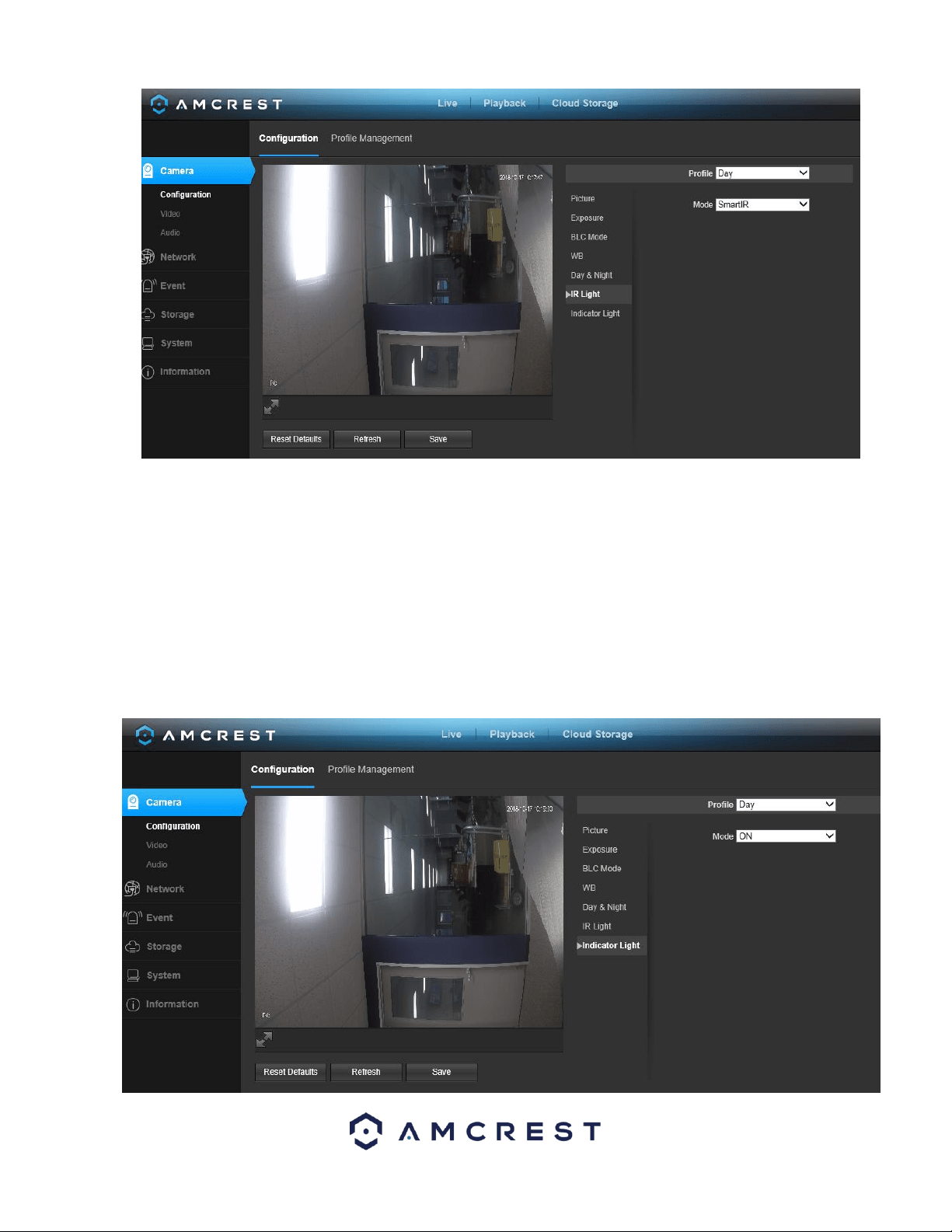
76
• Profile: This dropdown box allows the user to select which profile to modify. The 3 options are Day, Night, and Normal.
• Mode: This dropdown box allows the user to select whether to turn the indication light on or off. SmartIR can also be set to
automatically set the camera’s IR lights to on and off positions based on Day & Night conditions. This setting is usually set by
default within the camera.
To reset to default settings, click the Reset Defaults button. To refresh the screen, click on Refresh. To save the settings, click
the Save button.
5.4.1.7. Indicator Light
This menu box allows the user to select whether the indicator light in the camera is on or off for the selected profile. Below
is a screenshot of this menu:
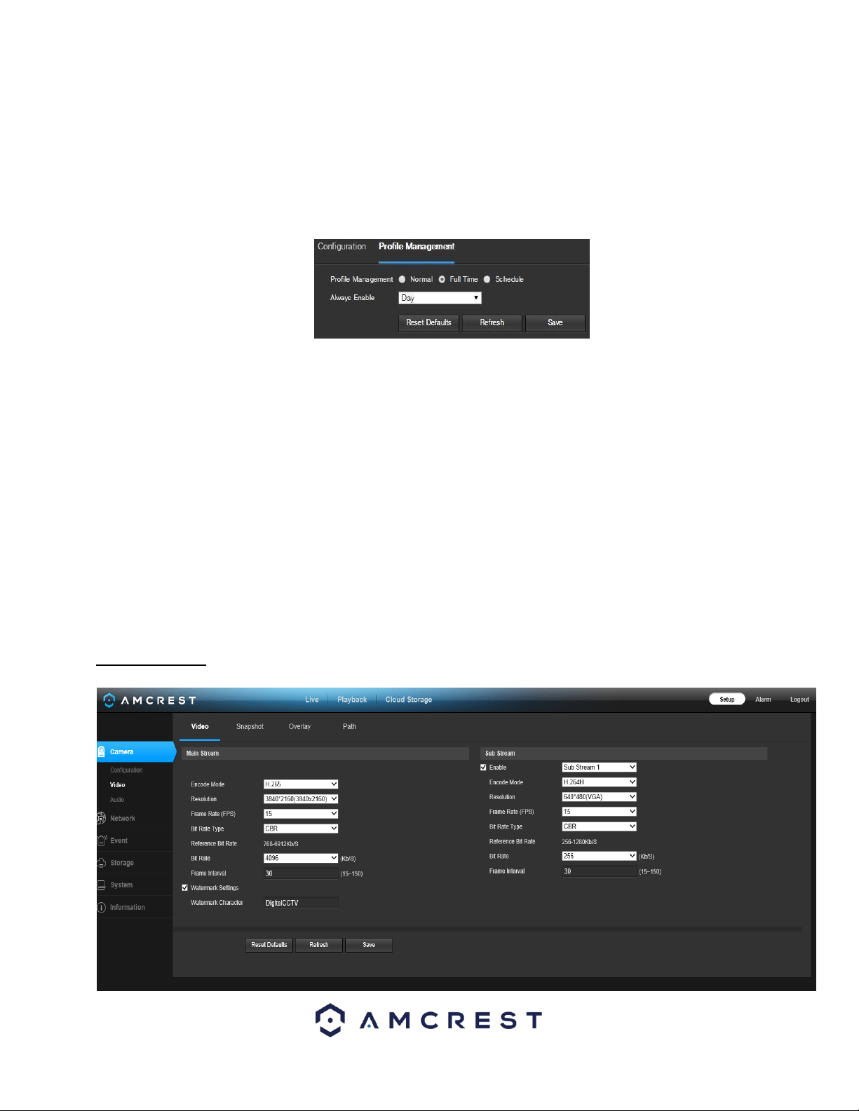
77
• Profile: This dropdown box allows the user to select which profile to modify. The 3 options are Day, Night, and Normal.
• Mode: This dropdown box allows the user to select whether to turn the indication light on or off.
To reset to default settings, click the Reset Defaults button. To refresh the screen, click on Refresh. To save the settings, click
the Save button.
5.4.1.8. Profile Management
Below is a screenshot that shows the Profile Management tab in the Configuration menu item:
Below is an explanation for each of the fields on the Profile Management tab in the Configuration menu item:
• Profile Management: This set of radio buttons allow the user to set what basis the profile management settings run on. There
are 3 options: Normal, Full Time, and Schedule. Normal means that the system can automatically alternate between night
and day based on the profiles for each.
Full Time means that the system sticks to one profile the entire time it is running. Schedule allows the user to dictate which
times of the day are designated for the day profile and the night profile.
To reset to default settings, click the Reset Defaults button. To refresh the page, click the Refresh button. To save the
settings, click the Save button.
5.4.1.2. Video
This section allows the user to change video settings for the camera’s video feed. There are 4 tabs in this menu item: Video,
Snapshot, Overlay, and Path.
5.4.1.2.1. Video
Below is a screenshot that shows the Video tab in the Video menu item:
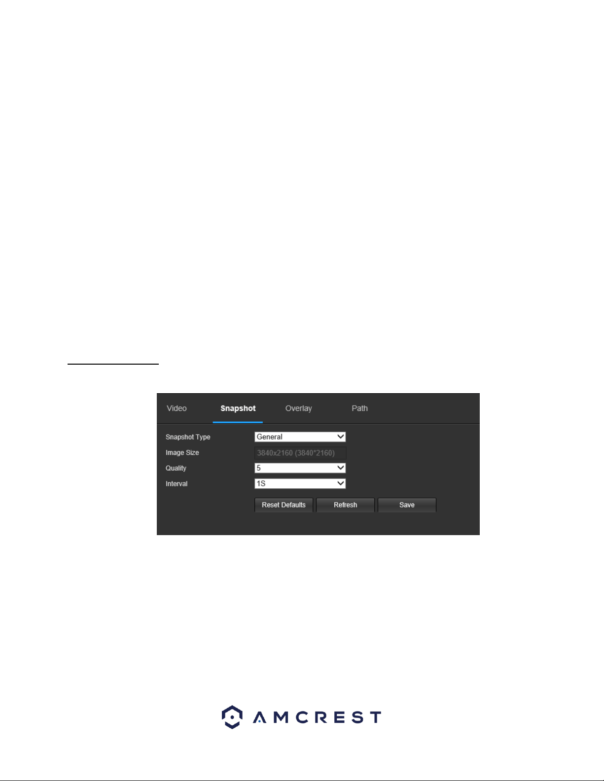
78
Below is an explanation for each of the fields on the Video tab in the Video menu item:
• Encode Mode: This dropdown box allows the user to select a compression protocol. The system supports H.264 and MJPEG
video compression protocols.
• Resolution: This dropdown box allows the user to set the resolution. The system supports various resolutions and they can
be selected from this dropdown list.
• Frame Rate (FPS): This dropdown box allows the user to select a frame rate. Frame rate settings are measured in frames per
second (FPS) and can range from 1f/s to 25f/s in PAL mode and 1f/s to 30f/s in NTSC mode.
• Bit Rate Type: This dropdown box allows the user to select a bit rate type. The system supports two bit rate types: CBR and
VBR. In VBR mode, video quality can be set.
• Reference Bit Rate: This is the recommended bit rate value according to the resolution and frame rate selected.
• Bit Rate: This dropdown box allows the user to select a bit rate.
• Frame Interval: This field allows the user to set the P frame amount between two I frames. The value ranges from 1 to 150
seconds. Default value is 50. Recommended value is frame rate *2.
• Watermark Settings: This function allows the user to verify if the video has been tampered with.
• Watermark Character: This field allows the user to set the watermark’s text. The default string is Digital CCTV. The maximum
length is 85 characters. This string can only include numbers, characters, and underscores.
Sub Stream is a lower quality stream that allows the feed to take up less resources and bandwidth when streaming. The
Main Stream and the Sub Stream have the same fields. Sub Stream can be enabled by checking the box next to Enable.
To reset to default settings, click the Reset Defaults button. To refresh the page, click the Refresh button. To save the
settings, click the Save button.
5.4.1.2.2 Snapshot
Below is a screenshot that shows the Snapshot tab in the Video menu item:
Below is an explanation for each of the fields on the Snapshot tab in the Video menu item:
• Snapshot Type: This dropdown box allows the user to select a snapshot mode. There are two snapshot modes:
▪ General: Snapshots are taken as scheduled.
▪ Event: Snapshots occur when a motion detection alarm or tampering alarm is triggered
• Image Size: This dropdown box shows the image size. By default, the screenshot size is the same size as the video feed’s
resolution.
• Quality: This dropdown box allows the user to select image quality. Quality is adjusted on a scale of
1-6.
• Interval: This is to set snapshot frequency. The value ranges from 1 to 7 seconds. The maximum setting for a customized
interval is 3600s/picture.
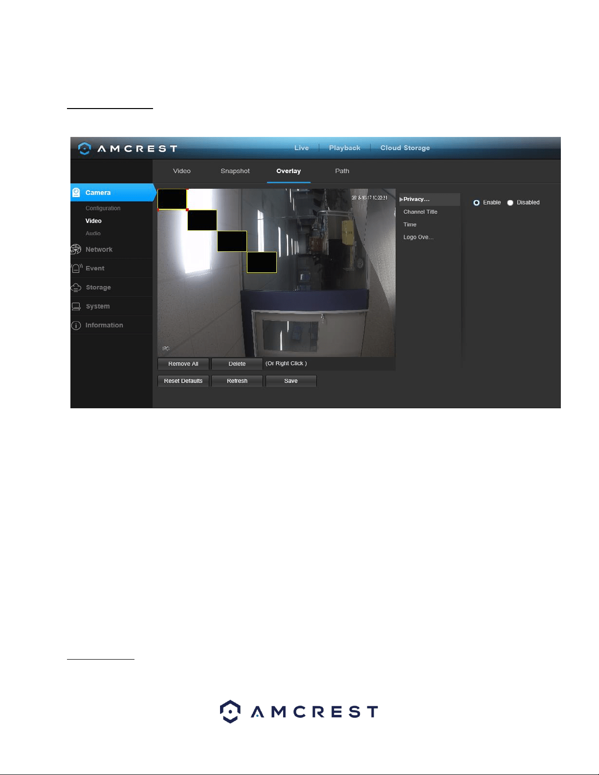
79
To reset to default settings, click the Reset Defaults button. To refresh the page, click the Refresh button. To save the
settings, click the Save button.
5.4.1.2.3. Overlay
Below is a screenshot that shows the Overlay tab in the Video menu item:
The menu on the left allows the user to select which overlay to modify. Privacy Masking, Channel Title, Time, and Text
Overlay can all be modified in this menu.
For Privacy Masking, the radio button enables or disables the feature. To set a privacy mask, click one of the boxes in the
live view window, and position or resize it as needed. To remove a box, click on it, then click the delete button. To remove all
privacy filter boxes, click the remove all button.
For Channel Title, the radio button enables or disables the feature. The Input Channel Title field allows the channel title to
be modified.
For Time, the radio button enables or disables the feature. Clicking the Display Weekdays checkbox will show the weekday
at the end of the timestamp.
For Text Overlay, the radio button enables or disables the feature. The Input Text box allows the user to enter multiple lines
of text as needed, and the Text Alignment dropdown box allows the user to align the text either right or left.
To reset to default settings, click the Reset Defaults button. To refresh the page, click the Refresh button. To save the
settings, click the Save button.
5.4.1.2.4 Path
Below is a screenshot that shows the Path tab in the Video menu item:
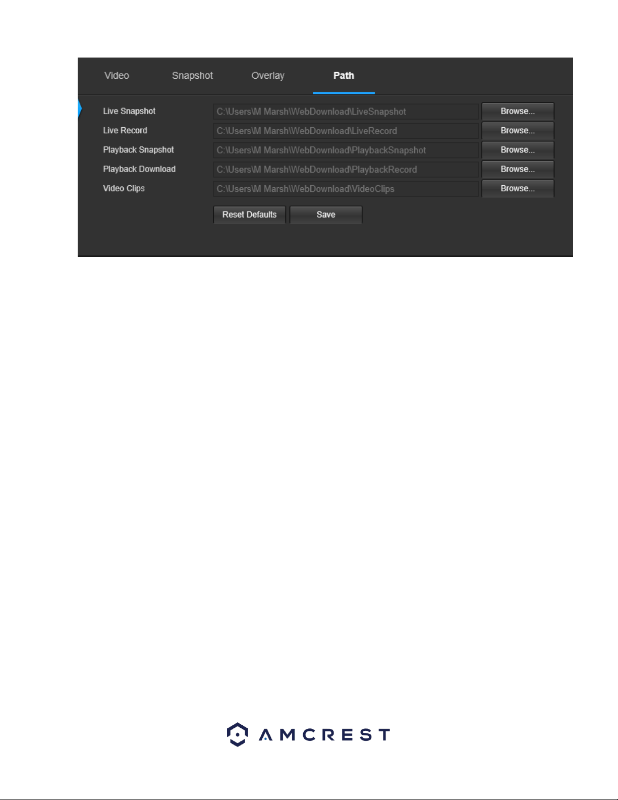
80
Below is an explanation for each of the fields on the Path tab in the Video menu item:
• The Live Snapshot field allows the user to select where to save live snapshots to. Click the Browse button to select a
different destination folder.
• The Live Record field allows the user to select where to save live recordings to. Click the Browse button to select a different
destination folder.
• The Playback Snapshot field allows the user to select where to save playback snapshots to. Click the Browse button to select
a different destination folder.
• The Playback Download field allows the user to select where to save playback video downloads to. Click the Browse button
to select a different destination folder.
• The Video Clips field allows the user to select where to save video clips to. Click the Browse button to select a different
destination folder.
To reset to default settings, click the Reset Defaults button. To save the settings, click the Save button.
5.4.2 Network
This menu section allows the user to change network settings for the camera.
5.4.2.1 TCP/IP
The TCP/IP menu item has two tabs: TCP/IP and P2P.
5.4.2.1.1 TCP/IP
TCP/IP stands for Transmission Control Protocol/Internet Protocol and it is the language/protocol that allows
communication between internet connected devices, whether on a local network, or a on the Internet at large. This screen
allows for TCP/IP settings to be modified for the camera to establish a connection to the network. Below is a screenshot of
the TCP/IP settings tab:
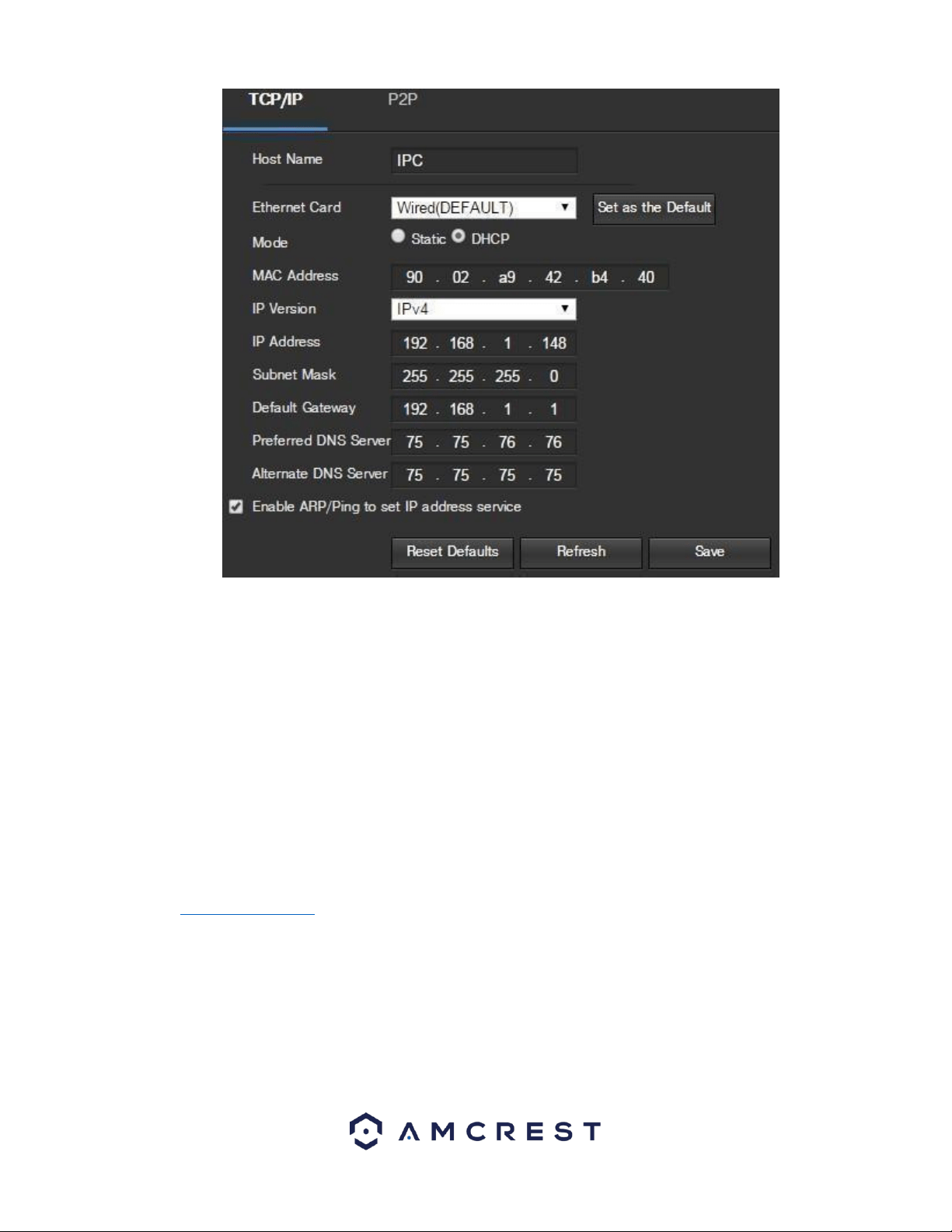
81
Below is an explanation of the fields on the TCP/IP settings tab:
• Host Name: This text field allows the user to change the host device name for the camera. This field supports a maximum of
15 characters.
• Ethernet Card: This dropdown box allows the user to select which internet access device to use. If the device is connected to
a wired connection and a wireless one at the same time, then this box will have options to pick either of the connections.
The Set as Default button allows the user to select one of the connection methods as the default one.
• Mode: Static vs DHCP: This radio button allows the user to choose between a static IP address, and a dynamic IP address.
DHCP stands for Dynamic Host Configuration Protocol, and this enables the camera to automatically obtain an IP address
from another network device such as a server or more commonly, a router. When the DHCP function is enabled, the user
cannot modify the IP address, Subnet Mask, or Default Gateway, as these values are obtained from the DHCP function. To
view the current IP address, DHCP needs to be disabled. Note: When PPPoE is enabled, modification of the IP Address,
Subnet Mask, and Gateway becomes prohibited.
Note: When connecting your device to an NVR or DVR, set the camera to Static. For more information on this process,
please visit amcrest.com/staticIP
• MAC Address: This field shows the camera’s MAC address, which is unique to this device. This number is read only and is
used to access a local area network (LAN).
• IP Version: This dropdown allows the user to select the IP version. The two options are IPV4 and
IPV6.
• IP Address: This field allows the user to enter a custom IP address.
• Subnet Mask: This field allows the user to enter a custom subnet mask.
• Default Gateway: This field allows the user to enter a custom default gateway.
• Preferred DNS Server: This field allows the user to enter the preferred DNS server
IP address.
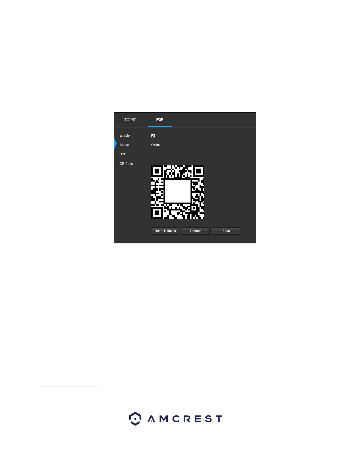
82
• Alternate DNS Server: This field allows the user to enter the alternate DNS server IP address.
• Enable ARP/Ping to set IP Address Service: This checkbox allows the user to enable the ARP/Ping service to change the IP
address service. For more information on this feature, click the help button while on the TCP/IP settings tab.
To reset to default settings, click the Reset Defaults button. To refresh the page, click the Refresh button. To save the
settings, click the Save button.
5.4.2.1.2 P2P
The P2P settings screen is where users can use a QR code to connect their smartphone or tablet to the camera. This feature
needs to be enabled for use with the Amcrest View app, Amcrest Cloud, or AmcrestView.com. Below is a screenshot of the
P2P settings tab:
Below is an explanation of the fields on the P2P settings tab:
Enable: This checkbox allows the user to enable the P2P feature for the camera. This feature must be enabled for the
camera to connect to a smartphone or tablet via the Amcrest View app. It is enabled by default.
• Status: This field displays the status of the P2P connection. Once the camera is connected to a device, this field should
display the word Online.
• S/N: This field displays the Token ID for the camera. The Token ID can be used to manually enter the camera’s information
on a mobile or tablet device in case the QR code scanning feature cannot be used.
• QR Code: This image is a Quick Response (QR) code. By scanning this image using the Amcrest View app, this camera can
establish a connection with the app.
To reset to default settings, click the Reset Defaults button. To refresh the page, click the Refresh button. To save the
settings, click the Save button.
5.4.2.2. Connection
The Connection menu item has two tabs: Connection and ONVIF.
5.4.2.2.1 Connection
The Connection tab is where users can configure port connections. Below is a screenshot of the Connection settings tab:
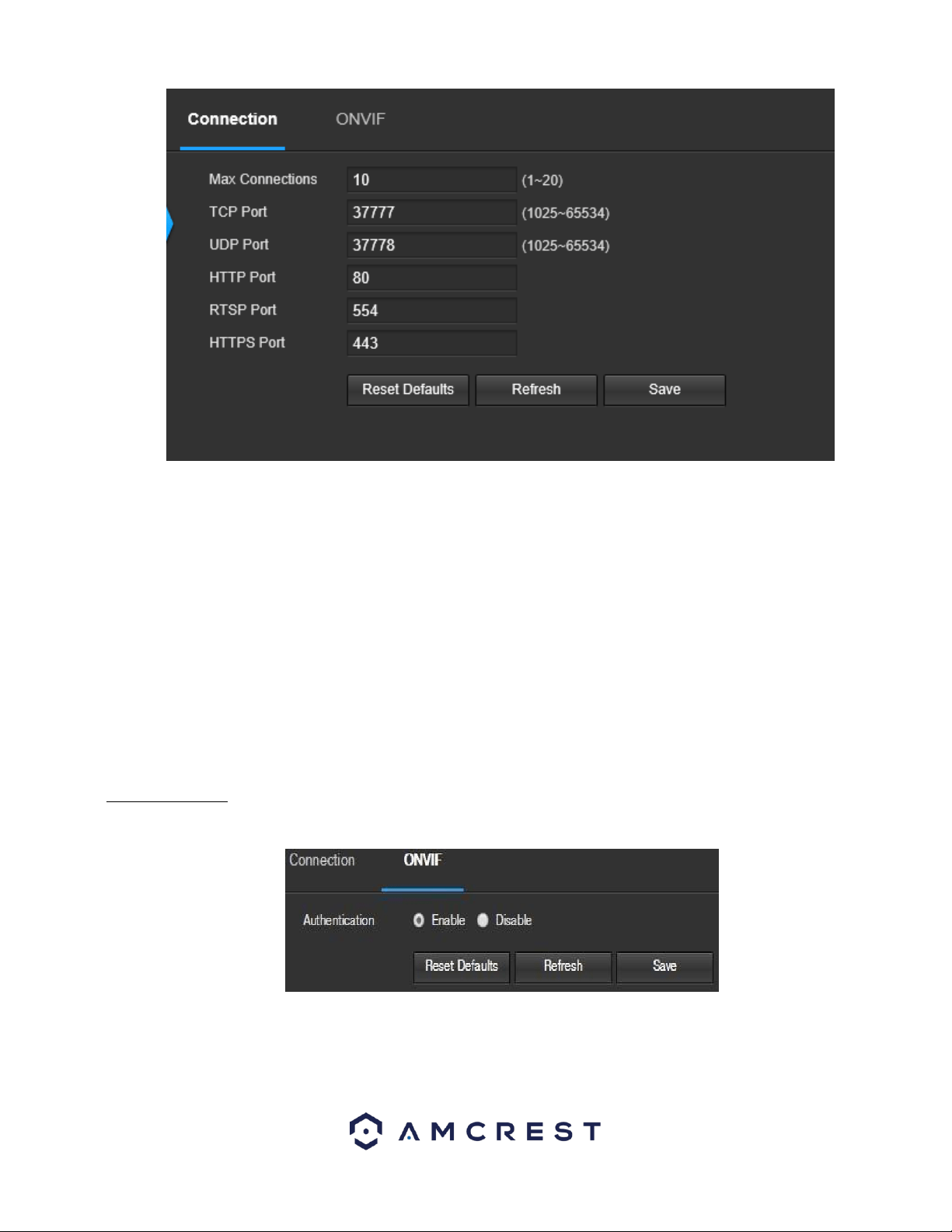
83
Below is an explanation of the fields on the Connection settings tab:
• Max Connections: This field allows the user to specify the maximum number of users that can be connected to the camera
at the same time. The maximum number of users the camera can support at one time is 20.
• TCP Port: This field designates the Transmission Control Protocol (TCP) port number. The default value is 37777.
• UDP Port: This field designates the User Datagram Protocol (UDP) port number. The default value is
37778.
HTTP Port: This field designates the Hypertext Transfer Protocol (HTTP) port number. The default value is 80.
• RTSP Port: This field designates the Real Time Streaming Protocol (RTSP) port number. The default value is 554.
• HTTPS: This field enables the use of the HTTPS protocol for accessing the camera.
• HTTPS Port: This field designates the Hypertext Transfer Protocol Secure (HTTPS) port number. The default value is 443.
To reset to default settings, click the Reset Defaults button. To refresh the page, click the Refresh button. To save the
settings, click the Save button.
5.4.2.2.2 ONVIF
The ONVIF tab is where users can configure authentication via the ONVIF standard. Below is a screenshot of the ONVIF
settings tab:
To enable ONVIF, click the radio button next to Enable, and then click the save button.
To reset to default settings, click the Reset Defaults button. To refresh the page, click the Refresh button. To save the
settings, click the Save button.
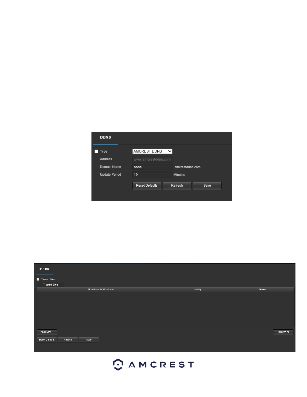
84
5.4.2.3. DDNS
DDNS stands for Dynamic Domain Name Server. This technology is used to automatically update name servers in real time to
help the camera maintain a persistent address despite changes in location or configuration. What this means is that even
when the camera is restarted, moved, or reconfigured, it can keep the same IP address, thus allowing remote users
uninterrupted access to the camera, rather than having to request a new IP address to use for remote access anytime a
change is made.
To use this feature, users will need to setup an account with a DDNS service. The camera supports a variety of DDNS services
such as Quick DDNS, NO-IP DDNS, CN99 DDNS, and Dyndns DDNS. Based on which service is selected, different options may
show on this screen. For purposes of this guide, AmcrestDDNS will be used. AmcrestDDNS is a free DDNS service provided by
Amcrest, and it must be renewed every year. A renewal reminder email will be sent to the email entered in the username
field below.
Below is a screenshot of the DDNS settings screen, configured to AmcrestDDNS:
To reset to default settings, click the Reset Defaults button. To refresh the page, click the Refresh button. To save the
settings, click the Save button.
5.4.2.4 IP Filter
This screen allows for the filtering of IP addresses, either blocking them, or granting them access to the camera. This feature
helps make the camera more secure by limiting remote access only to approved users. Below is a screenshot of the IP Filter
screen:
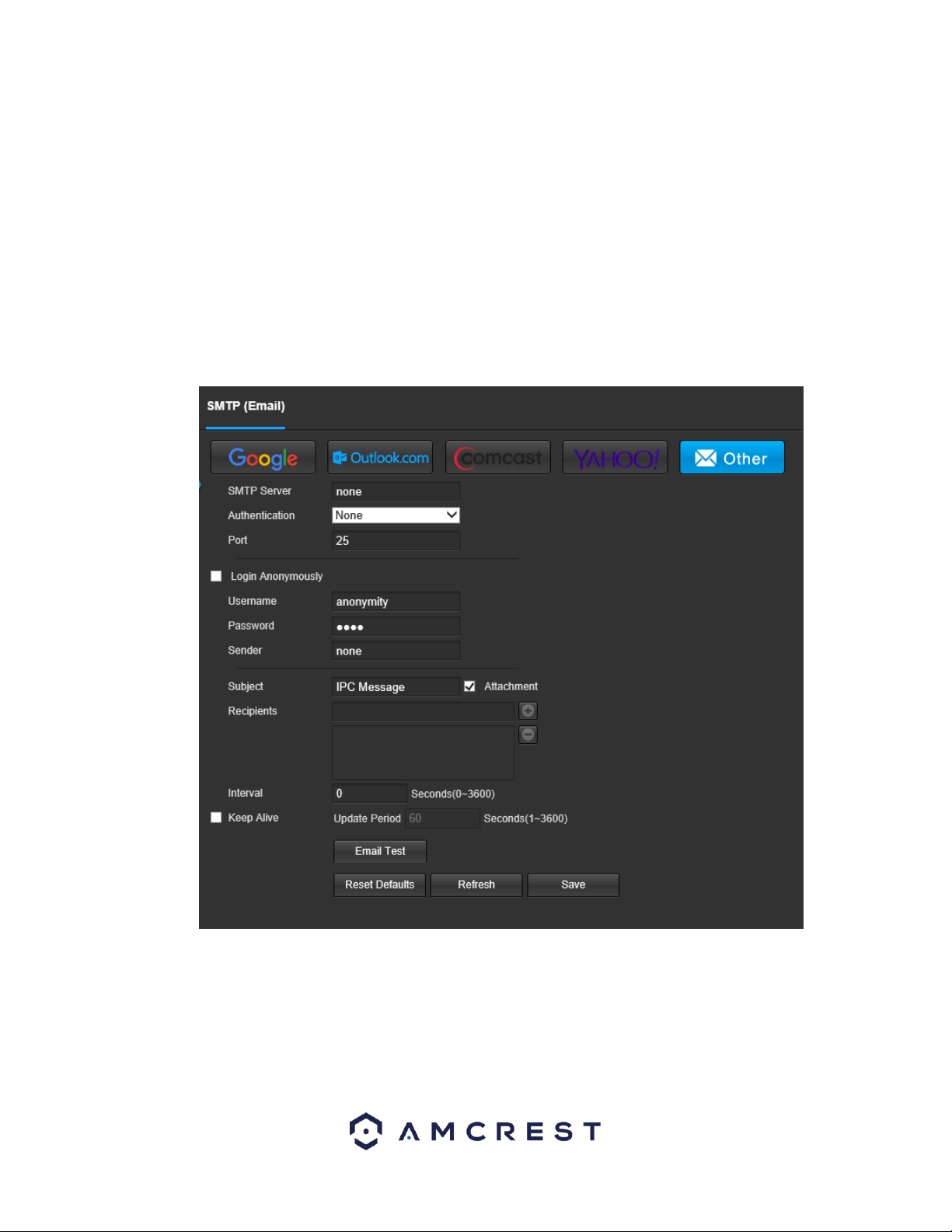
85
Below is an explanation of fields on the IP Filter settings screen:
• Trusted Sites: This checkbox allows the user to enable the IP Filter feature for trusted sites.
• Add IP/MAC: This button opens a popup that allows the user to add IP or MAC addresses to the trusted site list. Note: When
accessing the camera externally, please add the MAC address of the router on the PC end.
• Remove All: This button allows the user to remove all sites from the trusted IP/MAC list.
To reset to default settings, click the Reset Defaults button. To refresh the page, click the Refresh button. To save the
settings, click the Save button.
5.4.2.5. SMTP (Email)
This screen allows for the configuring of email settings to permit the camera to send emails when an alarm is triggered.
Below is a screenshot of the email settings screen:
Below is an explanation of fields on the SMTP (Email) settings screen:
• SMTP Server: SMTP stands for Simple Mail Transfer Protocol. This field allows the user to enter the SMTP server used by the
email service.
• Port: This field allows the user to enter the port that corresponds to the selected SMTP server.
• Login Anonymously: This checkbox allows the user to anonymously login to the server.
• Username: This field allows the user to enter the SMTP username.
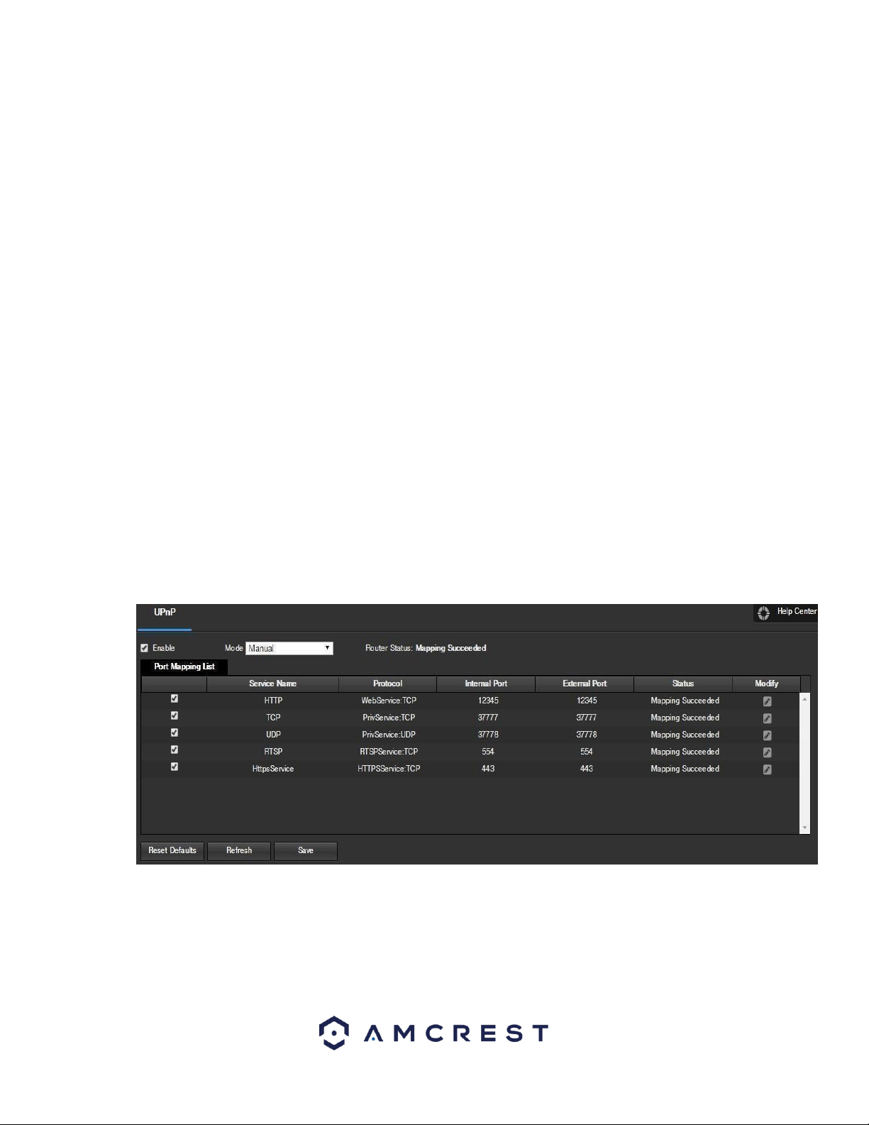
86
• Password: This field allows the user to enter the password associated with the SMTP username.
• Sender: This field allows the user to enter the sender email address. This email address will be the one that sends out all
emails pertaining to the alerts and alarm emails sent by the camera.
• Authentication: This dropdown box allows the user to select an encryption type. There are two types of email encryption
protocols that are available.
• SSL: Secure Socket Layer
• TLS: Transport Layer Security
• Subject: This field allows the user to define the subject line of the email that is sent to the receivers.
• Recipients: This field allows the user to enter the receiver email address. These email addresses are the ones that will
receive any emails pertaining to alert and alarm emails sent by the camera. Up to 3 email addresses can be entered in this
field.
Interval: This field allows the user to define, in seconds, how long the system should wait between sending emails. This
prevents multiple emails from being sent out.
• Keep Alive: This checkbox allows the user to enable a function to periodically check in with the SMTP server to ensure it can
connect correctly.
• Email Test: This button causes the system to automatically send out an email to test the connection is OK or not. Prior to the
email test, please save the email setup information.
To reset to default settings, click the Reset Defaults button. To refresh the page, click the Refresh button. To save the
settings, click the Save button.
5.4.2.6. UPnP
UPnP stands for Universal Plug and Play, and it is a protocol used to easily connect devices to the internet. In the case of this
camera, it allows the camera to connect to the router in an easy manner to quickly allow for remote access. Below is a
screenshot of the UPnP settings screen:
Below is an explanation of fields on the UPnP settings screen:
• Enable: This checkbox allows the user to enable the UPnP function.
• Router State: This field shows the UPnP status and has two options: Unknown: This means that
UPnP mapping has failed. Successful: This means that UPnP mapping has succeeded.
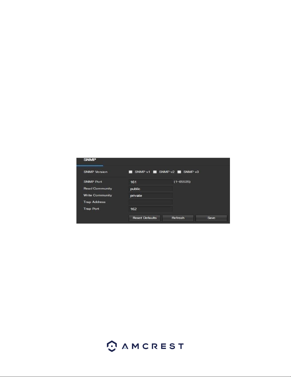
87
• Port Mapping List: This table is used to show how the ports for each protocol listed below have been remapped by the UPnP
protocol.
o The first column shows the checkboxes to enable the corresponding service on the table.
o The second column shows the name of the services. To edit this, double click on the service line item.
o The third column shows the name of the protocol used by that service. To edit this, click the pencil button in the modify
column for that line item.
o The fourth column shows the Internal Port used by that service to establish communication from the router to the camera.
To edit this, click the pencil button in the modify column for that line item.
o The fifth column shows the External Port used by that service to establish communication from the router to the internet. To
edit this, click the pencil button in the modify column for that line item.
o The sixth column shows the status of the protocol. If the protocol was mapped successfully, this field will say “Mapping
Succeeded”.
o The seventh column allows the user to open a dialog box and edit the service’s information.
To reset to default settings, click the Reset Defaults button. To refresh the page, click the Refresh button. To save the
settings, click the Save button.
5.4.2.7. SNMP
SNMP stands for Simple Network Management Protocol. This protocol is used to provide a basic framework to allow
connection between various network devices. Below is a screenshot of the SNMP settings screen:
Below is an explanation of fields on the SNMP settings screen:
• SNMP Version: These checkboxes allow the user to select the SNMP version to use.
SNMP Port: This field allows the user to write in a port for SNMP to use. The port can range from anywhere from 1 to 65535.
• Read Community: This field shows which SNMP community has read access.
• Write Community: This field shows which SNMP community has write access.
• Trap Address: This field allows the user to write in a trap address.
• Trap Port: This field allows the user to write in a trap port number. The trap port number should not be the same as the
SNMP port.
Note: This feature may not be available on all model cameras.
To reset to default settings, click the Reset Defaults button. To refresh the page, click the Refresh button. To save the
settings, click the Save button.
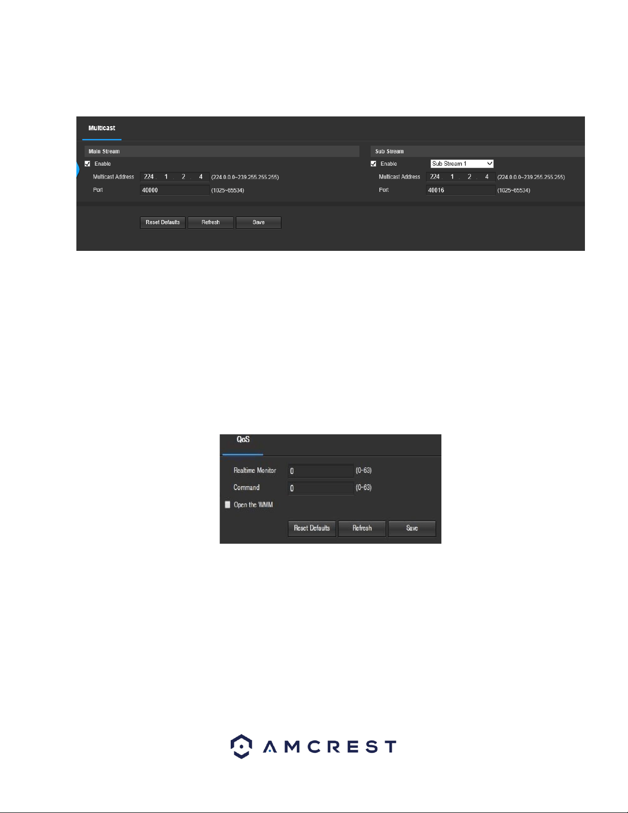
88
5.4.2.8. Multicast
Multicast is a feature that enables the camera to broadcast its live view to multiple computers on the same network. Below
is a screenshot of the multicast screen:
Below is an explanation of the fields in the Multicast settings screen:
• Enable: This checkbox allows the user to enable Multicast functionality.
• Multicast Address: This field allows the user to enter a multicast address.
• Port: This field allows the user to enter a multicast port.
To reset to default settings, click the Reset Defaults button. To refresh the page, click the Refresh button. To save the
settings, click the Save button.
5.4.2.9. QoS
QoS stands for Quality of Service and it refers to the overall performance of a computer network, particularly the
performance seen by the users of the network. Below is a screenshot of the QoS screen:
Below is an explanation of the fields on the QoS screen:
• Realtime Monitor: This field allows the user to enter in a priority value for real time monitoring packets. The range is
between 0-63.
• Command: This field allows the user to enter in a priority value for command packets. The range is between
063.
To reset to default settings, click the Reset Defaults button. To refresh the page, click the Refresh button. To save the
settings, click the Save button.
5.4.2.10. HTTPS
This menu allows the user to enable and create HTTPS certificates. Below is a screenshot of this menu:
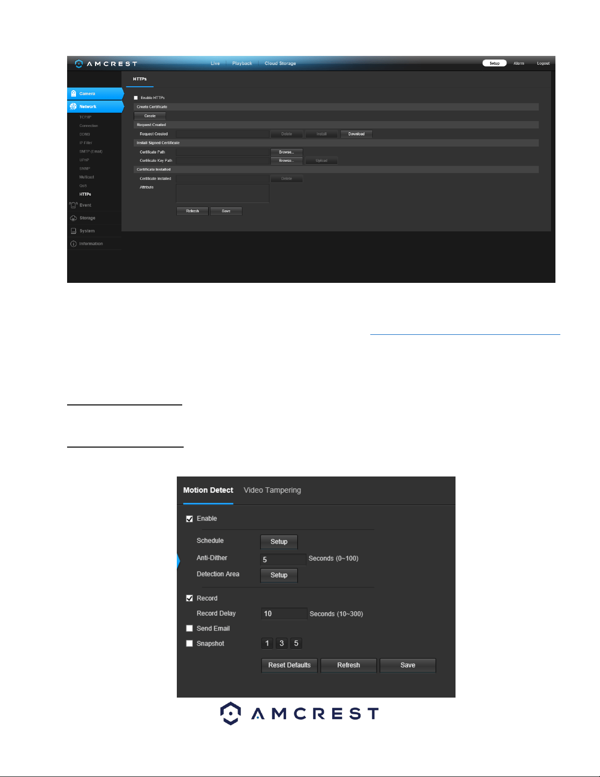
89
Before you create certificate or download certificate, from main window->Setup->Network >Connection, set the HTTPS port
values and then check the box to enable HTTPS
For more information on how to setup HTTPS in the web user interface visit https://www.youtube.com/watch?v=gkjlaf-Iuso
5.4.3 Event
This menu section allows the user to change different settings for triggering events.
5.4.3.1 Video Detection
The video detection menu has two tabs: Motion Detect and Video Tamper.
5.4.3.1.1 Motion Detect
This tab allows the user to modify motion detection settings. Below is a screenshot of the Motion Detect tab:
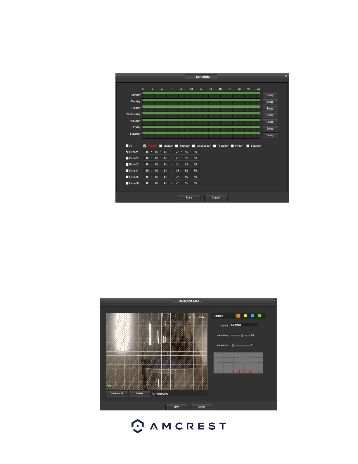
90
Below is an explanation of the fields on the Motion Detect tab:
Enable: This checkbox enables motion detection for the camera.
Schedule: Clicking this button opens a weekly schedule that can be used to set times.
o Click and drag to set motion detection for certain days of the week. Also, periods of motion detection can be set for each
day and enabled using the period settings on the bottom half of the screen. There are a total of 6 periods that can be set.
Anti-Dither: This field allows the user to set the anti-dither time. The values in this field can range from 5 to 600 seconds.
This time value controls how long the alarm signal lasts. Based on motion detection, a buzzer can go off, a tour can begin, , a
snapshot can be taken, or the camera can begin recording.
o For example, if the anti-dither time is set to 10 seconds, each alarm may last 10 seconds if the local alarm is activated.
During the process, if the system detects another local alarm signal at the fifth second, the buzzer, tour, snapshot, record
channel functions will begin another 10 seconds while the screen prompt, alarm upload, email will not be activated again.
After 10 seconds, if system detects another alarm signal, it can generate a new alarm since the anti-dither time has expired.
• Detection Area: Clicking this button opens a pop-up screen that can be used to set detection areas.
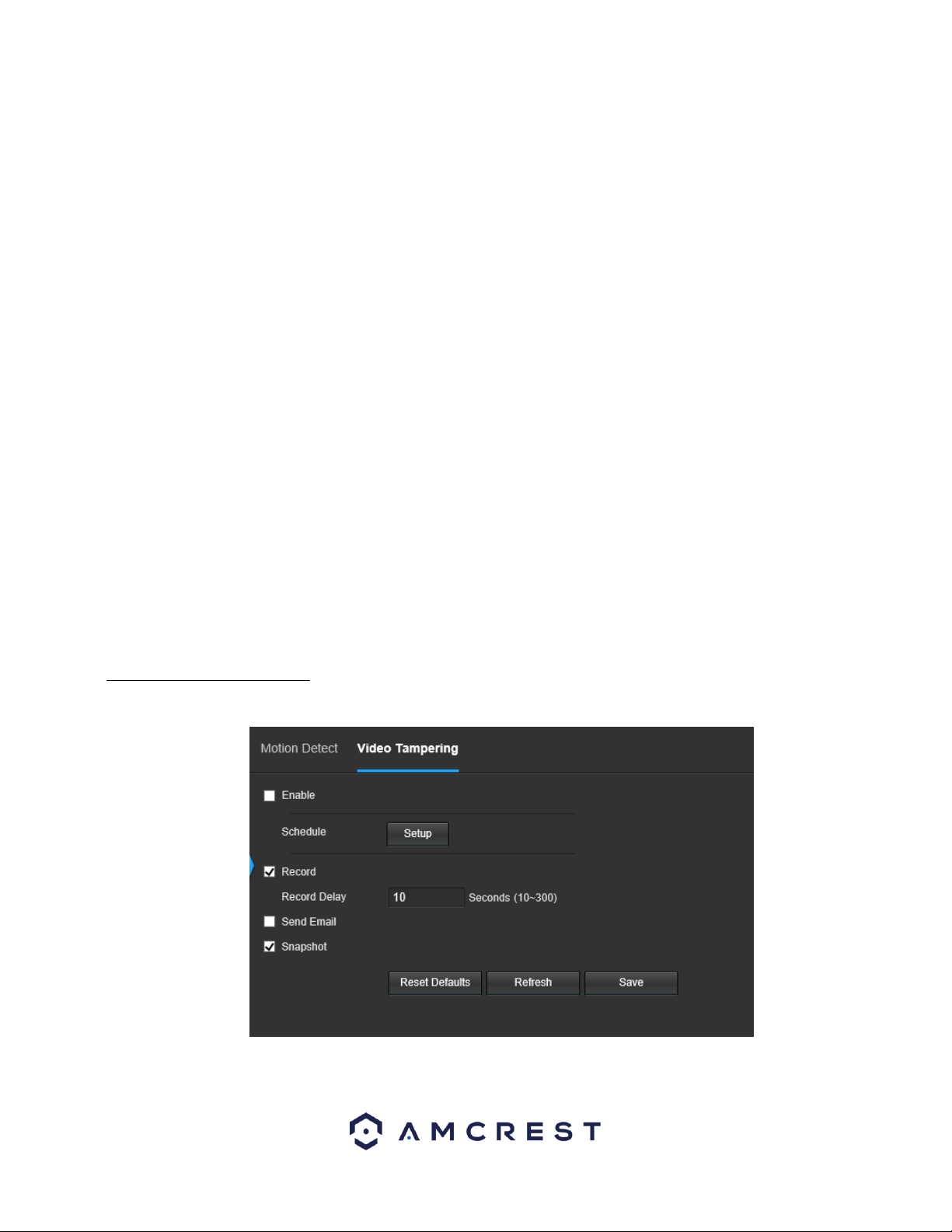
91
o When the setup button is clicked, a live stream of the video is shown. The user can then set up to 4 regions, each with
their own region name, sensitivity (1-100), and threshold (1-100). Each region has a specific color, and the region selector
tool is displayed when the mouse is moved to the top of the screen.
Sensitivity is the amount of change required to increase the motion detected by a percentage. The lower the sensitivity, the
more movement is required to trigger an alarm.
Threshold is the level that the motion detection needs to reach to trigger an alarm. The lower the threshold, the more likely
that motion will trigger an alarm.
To designate a zone, click and drag the mouse over the area desired. When a colored box is displayed over the live feed, that
area is now enabled for motion detection.
After the motion detection zone is set, click the enter button to exit the motion detection screen.
Remember to click the save button on the motion detection settings screen, otherwise the motion detection zones will not
go into effect. Clicking the cancel button to leave the motion detection zone and will not save the zone setup.
• Record: This checkbox allows the user to enable the camera to record video when a motion detection alarm is triggered.
• Record Delay: This field specifies in seconds how long the delay between alarm activation and recording should be.
• Relay Out: This checkbox allows the user to enable the camera to trigger a connected alarm (connected to the alarm port on
the back of the camera) when a motion detection alarm is triggered.
• Alarm Delay: This field specifies in seconds how long the delay between alarm activation and Relay alarm activation should
be.
• Send Email: This checkbox allows the user to enable the camera to send an email when a motion detection alarm is
triggered.
• Snapshot: This checkbox allows the user to enable the camera to take a snapshot when a motion detection alarm is
triggered.
To reset to default settings, click the Reset Defaults button. To refresh the page, click the Refresh button. To save the
settings, click the Save button.
5.4.3.1.2 Video Tampering
This tab allows the user to modify video tamper settings. Below is a screenshot of the Video Tamper tab:
Below is an explanation of the fields on the Video Tamper tab:
• Enable: This checkbox enables a video tamper alarm for the camera.
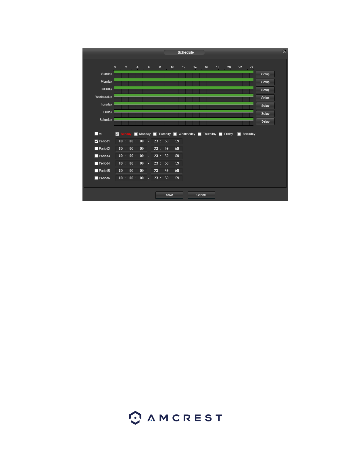
92
• Schedule: Clicking this button opens a weekly schedule that can be used to set times.
o Click and drag to set video tampering for certain days of the week. Also, periods of video tampering can be set for each day
and enabled using the period settings on the bottom half of the screen. There are a total of 6 periods that can be set.
• Record: This checkbox allows the user to enable the camera to record video when a video tampering alarm is triggered.
• Record Delay: This field specifies in seconds how long the delay between alarm activation and recording should be.
• Relay Out: This checkbox allows the user to enable the camera to trigger a connected alarm (connected to the alarm port on
the back of the camera) when a video tamper alarm is triggered.
• Alarm Delay: This field specifies in seconds how long the delay between alarm activation and Relay alarm activation should
be.
Send Email: This checkbox allows the user to enable the camera to send an email when a video tampering alarm is triggered.
• Snapshot: This checkbox allows the user to enable the camera to take a snapshot when a video tampering alarm is triggered.
To reset to default settings, click the Reset Defaults button. To refresh the page, click the Refresh button. To save the
settings, click the Save button.
5.4.3.3 Abnormality
This menu allows the user to adjust abnormality event settings. This menu has 3 tabs: SD Card, Network, and Illegal Access.
5.4.3.3.1 SD Card
This tab allows the user to set the camera’s response to an SD card related abnormality. Below is a screenshot of the SD card
tab screen:
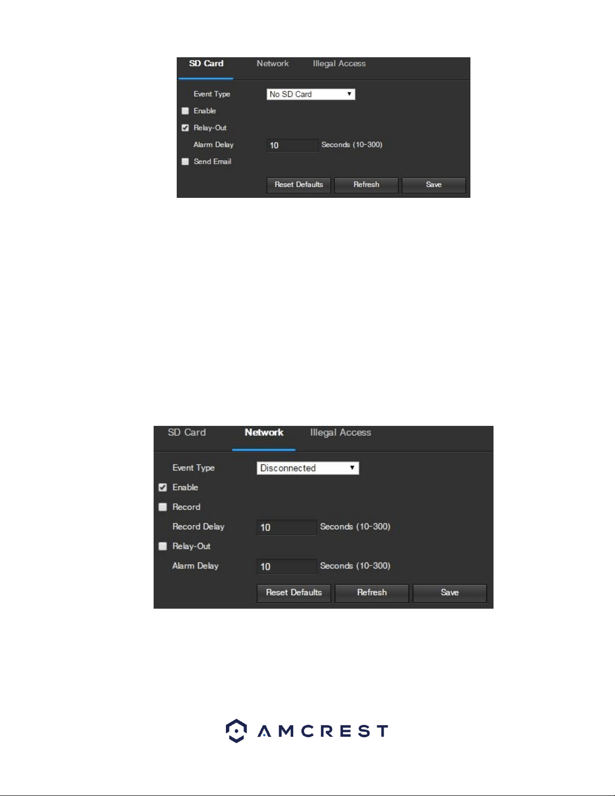
93
Below is an explanation of the fields on the SD Card settings tab:
• Event Type: This dropdown box allows the user to select which SD card abnormality to set event triggers for. The 3 options
are No SD Card, SD Card Error, and Capacity Warning.
• Enable: This checkbox enables the SD Card abnormality trigger for the camera.
• Relay Out: This checkbox allows the user to enable the camera to trigger an alarm when an SD Card abnormality is detected.
• Alarm Delay: This field specifies in seconds how long the delay between alarm activation and relay alarm activation should
be.
• Send Email: This checkbox allows the user to enable the camera to send an email when an SD Card abnormality is detected.
To reset to default settings, click the Reset Defaults button. To refresh the page, click the Refresh button. To save the
settings, click the Save button.
5.4.3.3.2 Network
This tab allows the user to set the camera’s response to a Network related abnormality. Below is a screenshot of the
Network tab screen:
Below is an explanation of the fields on the Network settings tab:
• Event Type: This dropdown box allows the user to select which Network abnormality to set event triggers for. The 2 options
are Disconnection and IP Conflict.
• Enable: This checkbox enables the Network abnormality trigger for the camera.
• Record: This checkbox allows the user to enable the camera to record video when a network abnormality is detected.
• Record Delay: This field specifies in seconds how long the delay between alarm activation and recording should be.
• Relay Out: This checkbox allows the user to enable the camera to trigger an alarm when a network abnormality is detected.
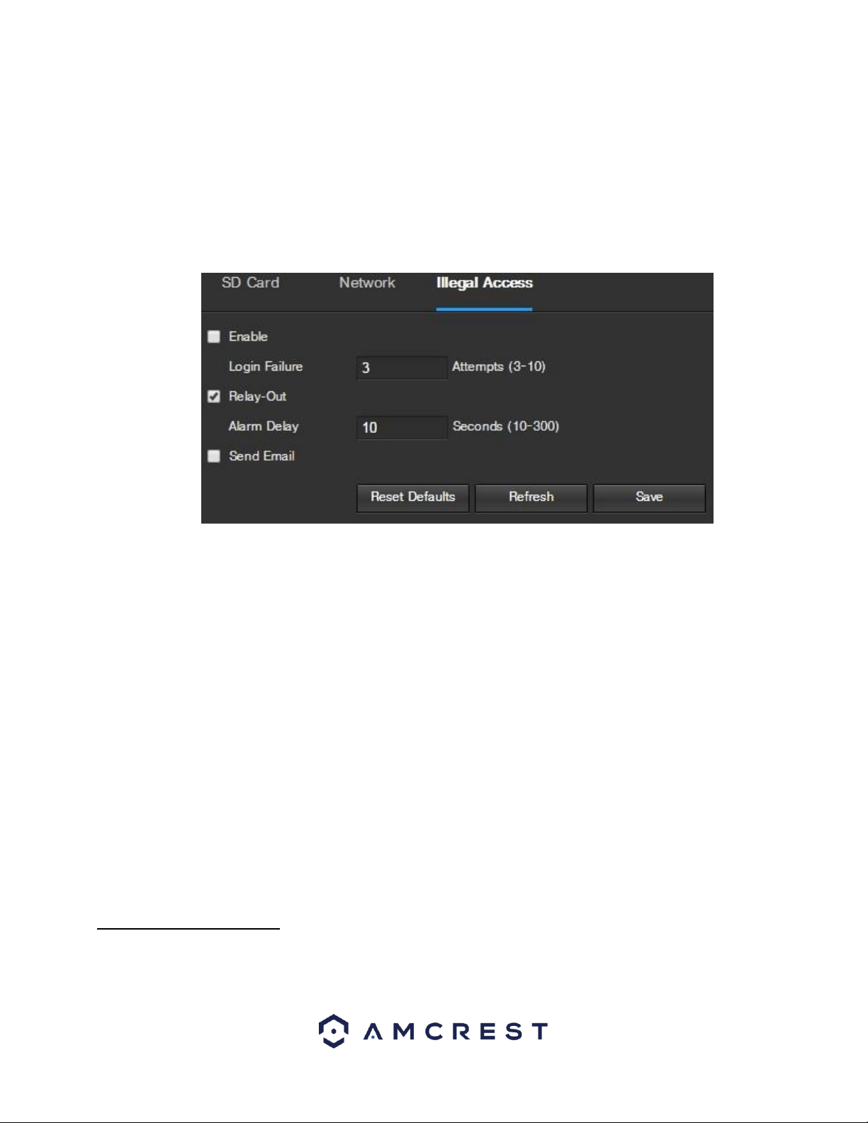
94
• Alarm Delay: This field specifies in seconds how long the delay between alarm activation and relay alarm activation should
be.
To reset to default settings, click the Reset Defaults button. To refresh the page, click the Refresh button. To save the
settings, click the Save button.
5.4.3.3.3 Illegal Access
This tab allows the user to set the camera’s response to an Illegal Access related abnormality. Below is a screenshot of the
Illegal Access tab screen:
Below is an explanation of the fields on the Illegal Access settings tab:
• Enable: This checkbox enables the Illegal Access abnormality trigger for the camera.
• Login Failure: This field allows the user to specify how many failed login attempts must be attempted to trigger an Illegal
Access abnormality event.
• Relay Out: This checkbox allows the user to enable the camera to trigger an alarm when illegal access is detected.
• Alarm Delay: This field specifies in seconds how long the delay between alarm activation and relay alarm activation should
be.
• Send Email: This checkbox allows the user to enable the camera to send an email when illegal access is attempted.
To reset to default settings, click the Reset Defaults button. To refresh the page, click the Refresh button. To save the
settings, click the Save button.
5.4.4 Storage
This menu section allows the user to change storage settings for the camera.
5.4.4.1 Schedule
The schedule menu manages the recording schedule for the camera. This menu has 3 tabs: Record Schedule, Snapshot
Schedule, and Holiday Schedule.
5.4.4.1.1 Record Schedule
This tab is where video recording settings are configured. Below is a screenshot of the Record Schedule settings screen:
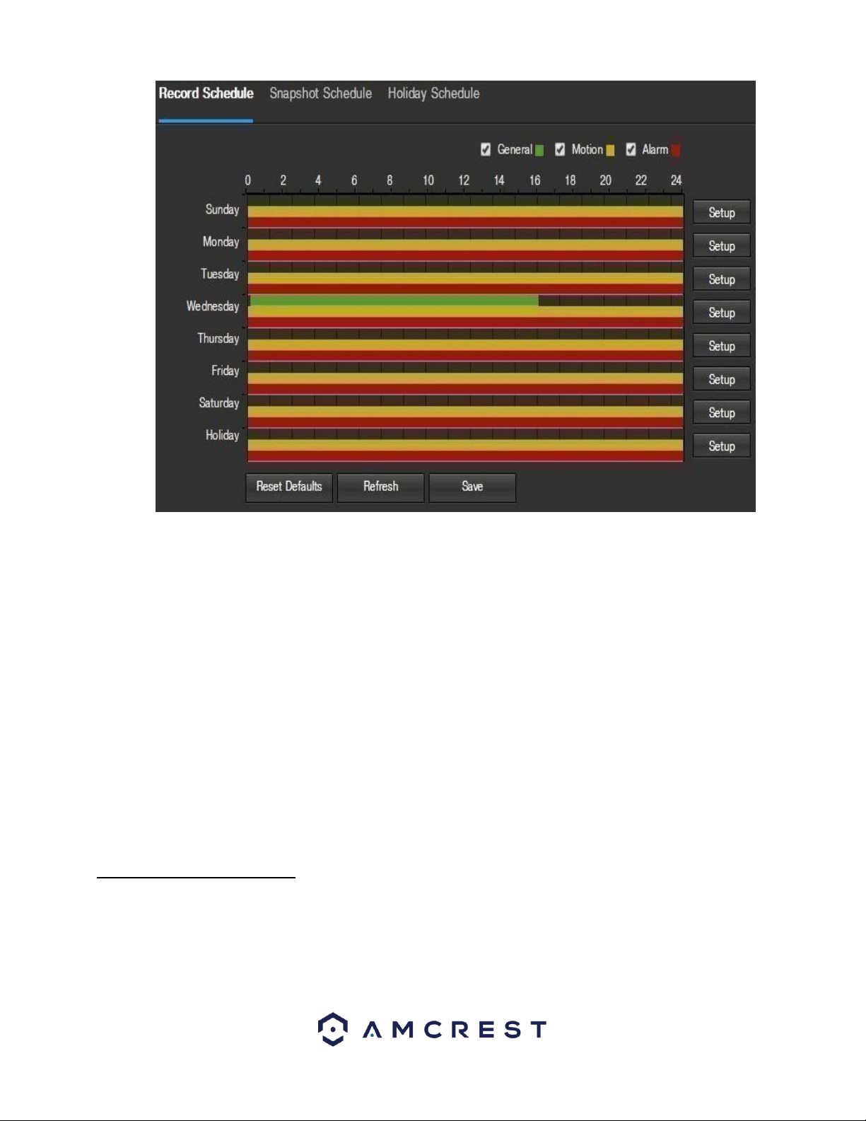
95
Below is an explanation of the fields on the Record Schedule settings tab:
Record Type: These checkboxes allow the user to select which recording type they want to configure on the schedule. There
are 3 types of recordings:
o General: General recording means that the camera captures all footage for the specified time period. General recording is
represented by the color green.
o Motion: Motion Detection recording means that the camera captures only footage when the motion detection alarm is
activated. Motion recording is represented by the color yellow.
o Alarm: Alarm recording means that the camera captures only footage when an alarm is activated. Alarm recording is
represented by the color red.
• Video Recording Schedule: To specify a video recording range, first select the type of recording desired, then click and drag
on time bar for the desired date. To edit multiple days at once, drag the cursor further up or down to cover the other days.
o Setup: Clicking this button opens a screen that allows for recording periods to be set for each day and for each recording type.
There are a total of 6 periods that can be set.
To reset to default settings, click the Reset Defaults button. To refresh the page, click the Refresh button. To save the
settings, click the Save button.
5.4.4.1.2 Snapshot Schedule
This tab is where snapshot recording settings are configured. Below is a screenshot of the Snapshot Schedule settings
screen:
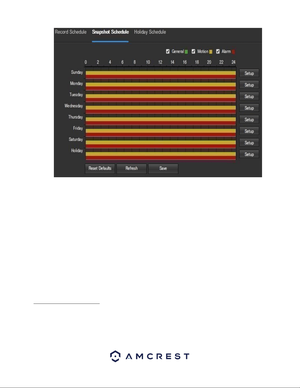
96
Below is an explanation of the fields on the Snapshot Schedule settings tab:
• Record Type: These checkboxes allow the user to select which snapshot type they want to configure on the schedule. There
are 3 types of snapshots:
o General: General means that the camera will take snapshots during the specified time period. General recording is
represented by the color green.
o Motion: Motion Detection means that the camera only takes snapshots when the motion detection alarm is activated.
Motion recording is represented by the color yellow.
o Alarm: Alarm means that the camera only takes snapshots when an alarm is activated. Alarm recording is represented by
the color red.
• Snapshot Recording Schedule: To specify a snapshot range, first select the type of snapshot desired, then click and drag on
time bar for the desired date. To edit multiple days at once, drag the cursor further up or down to cover the other days.
o Setup: Clicking this button opens a screen that allows for snapshot periods to be set for each day and for each snapshot
type. There are a total of 6 periods that can be set.
To reset to default settings, click the Reset Defaults button. To refresh the page, click the Refresh button. To save the
settings, click the Save button.
5.4.4.1.3. Holiday Schedule
This tab is where holiday settings are configured. Below is a screenshot of the Holiday Schedule settings screen:
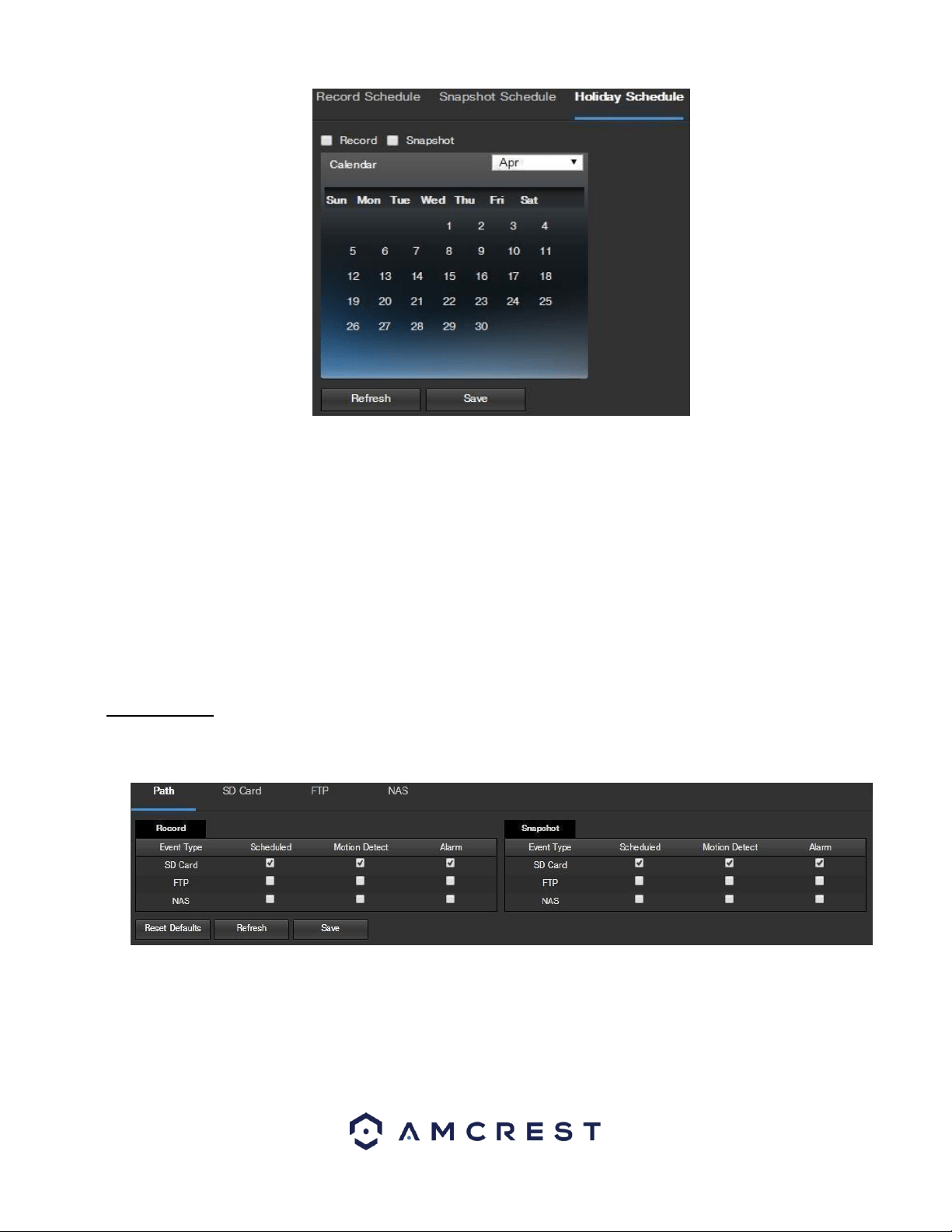
97
Below is an explanation of the fields on the Holiday Schedule settings tab:
• Record Type: These checkboxes allow the user to select which recording type they want to configure on the schedule. There
are 2 types of recordings:
o Record: This checkbox is referring to video recording.
o Snapshot: This checkbox is referring to snapshot recording.
• Calendar: This calendar allows the user to select days to designate as holidays. Once a day is designated, it can be
customized to stop recording or snapshots for that day by using the Record and Snapshot checkboxes.
To refresh the page, click the Refresh button. To save the settings, click the Save button.
5.4.4.2 Destination
This menu controls where recorded media is stored. There are 4 tabs in this menu: Path, SD Card, FTP, and NAS.
5.4.4.2.1 Path
This tab is where the user can designate a path for recorded video and snapshots to reside in. Below is a screenshot of the
Path tab:
Below is an explanation of the fields on the Path settings tab:
• Event Type: This column designates storage options available to the camera. The options are SD Card, FTP, and NAS.
• Record Type: These columns designate which recording type should be recorded to which event type. Check the box at the
intersection of the record type and event type to designate where that recording should be sent to.
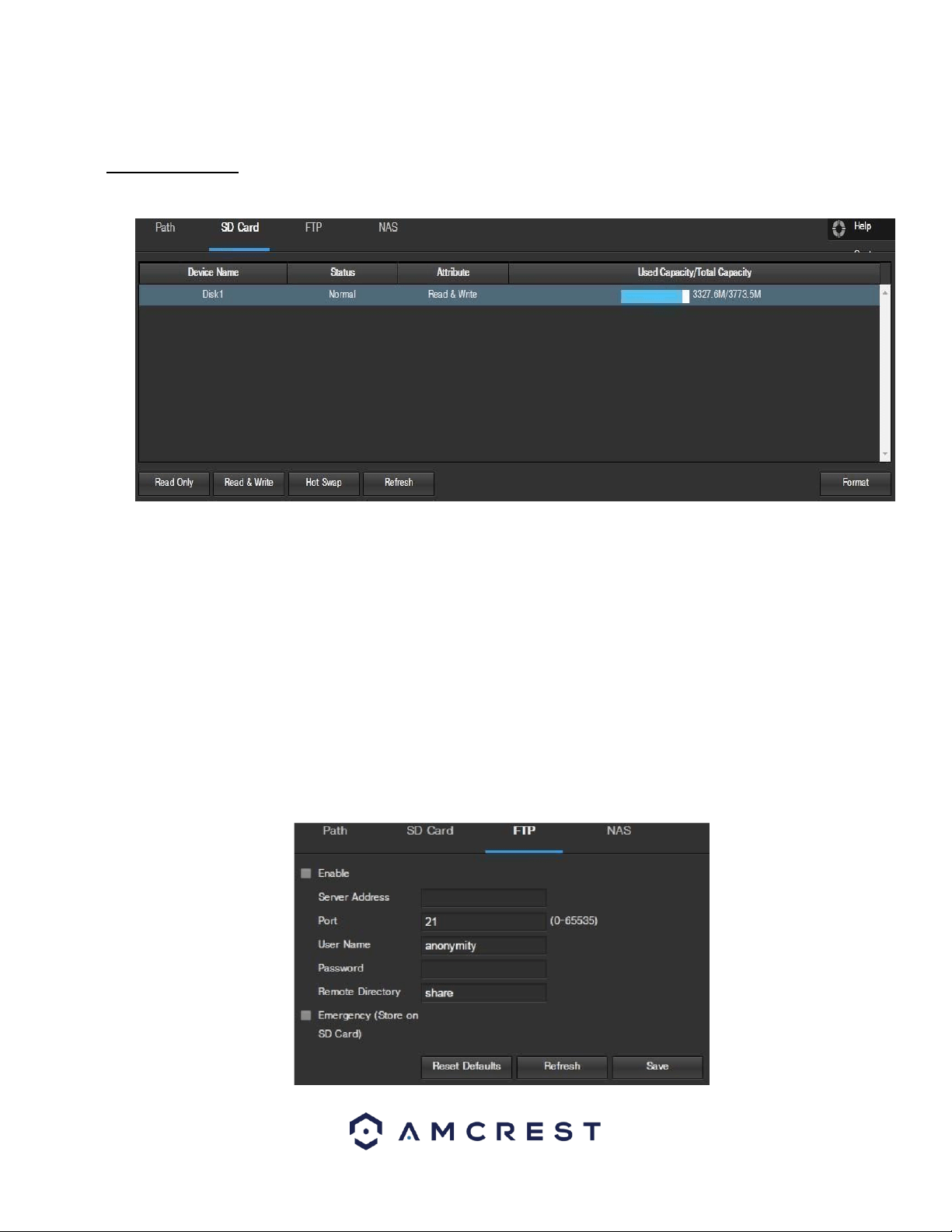
98
To reset to default settings, click the Reset Defaults button. To refresh the page, click the Refresh button. To save the
settings, click the Save button.
5.4.4.2.2 SD Card
This tab is where the user can change SD card settings. Below is a screenshot of the SD Card tab:
Below is an explanation of the fields on the SD Card settings tab:
• Device Name: This column designates the name of the SD card that is currently in the camera.
• Status: This column designates the status of the SD card.
• Attribute: This column designates the read/write attributes for the SD card. By default, this is Read &
Write.
• Used Capacity/Total Capacity: This column shows the available memory on the SC card.
Read Only: This button allows the user to designate an SD card as read only.
• Hot Swap: This button allows the user to physically remove the SD card and replace it with another safely.
• Refresh: This button refreshes the SD card table.
• Format: This button formats the SD card.
5.4.4.2.3 FTP
This tab is where the user can change FTP settings. Below is a screenshot of the FTP tab:
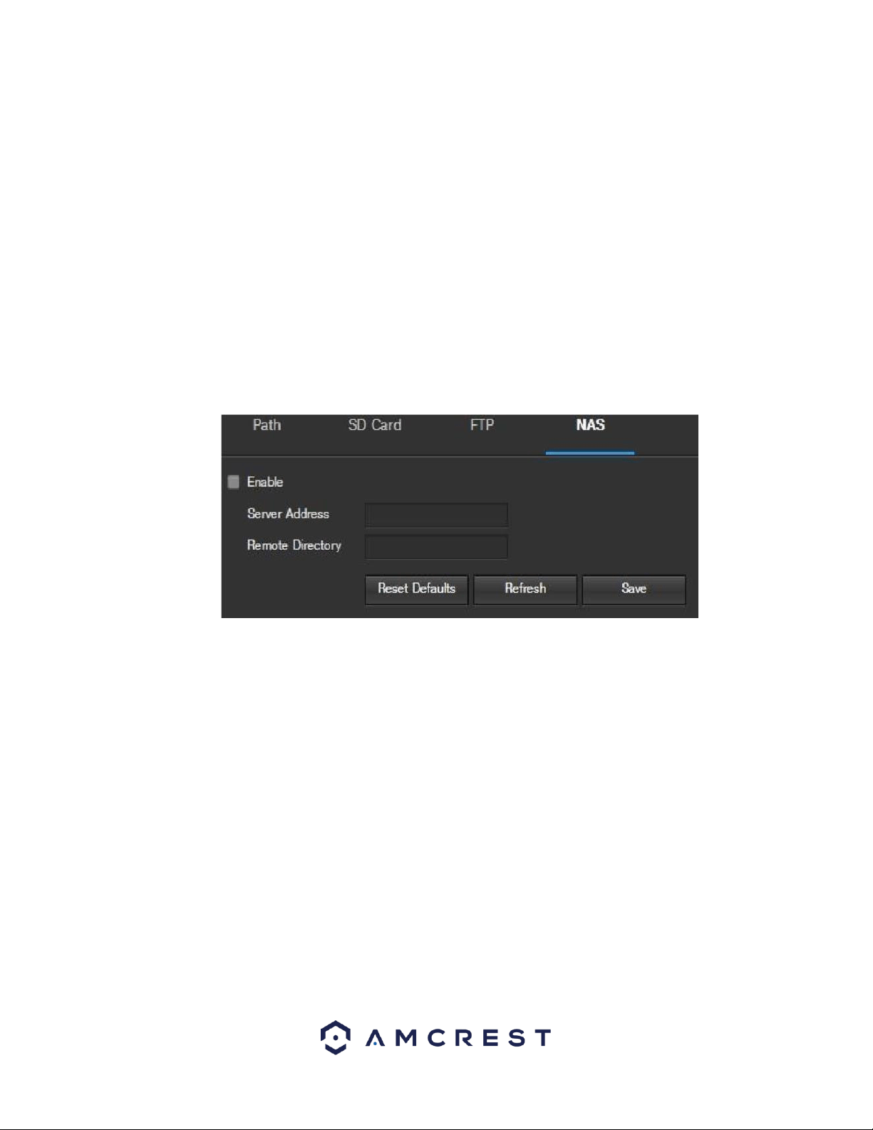
99
Below is an explanation of the fields on the FTP settings tab:
• Enable: This checkbox allows the user to enable FTP uploading for the camera’s recorded media.
• Server Address: This field allows the user to designate a DDNS address for the FTP server.
• Port: This field allows the user to designate the port number for the FTP server.
• User Name: This field allows the user to input the username used to login to the FTP server.
• Password: This field allows the user to input the password used to login to the FTP server.
• Remote Directory: This field allows the user to specify a remote directory on the FTP to send the recorded media to.
• Emergency (Store on SD Card): This checkbox allows the camera to store recorded media on the SD card in case the FTP
server is unavailable.
To reset to default settings, click the Reset Defaults button. To refresh the page, click the Refresh button. To save the
settings, click the Save button.
5.4.4.2.4 NAS
This tab is where the user can change NAS settings. Below is a screenshot of the NAS tab:
Below is an explanation of the fields on the NAS settings tab:
• Enable: This checkbox allows the user to enable NAS uploading for the camera’s recorded media. • Server Address: This
field allows the user to designate a DDNS address for the NAS server/device.
• Remote Directory: This field allows the user to specify a remote directory on the NAS to send the recorded media to.
•
To reset to default settings, click the Reset Defaults button. To refresh the page, click the Refresh button. To save the
settings, click the Save button.
5.4.4.3 Record Control
This menu is where general recording settings are configured. Below is a screenshot of the record control menu:
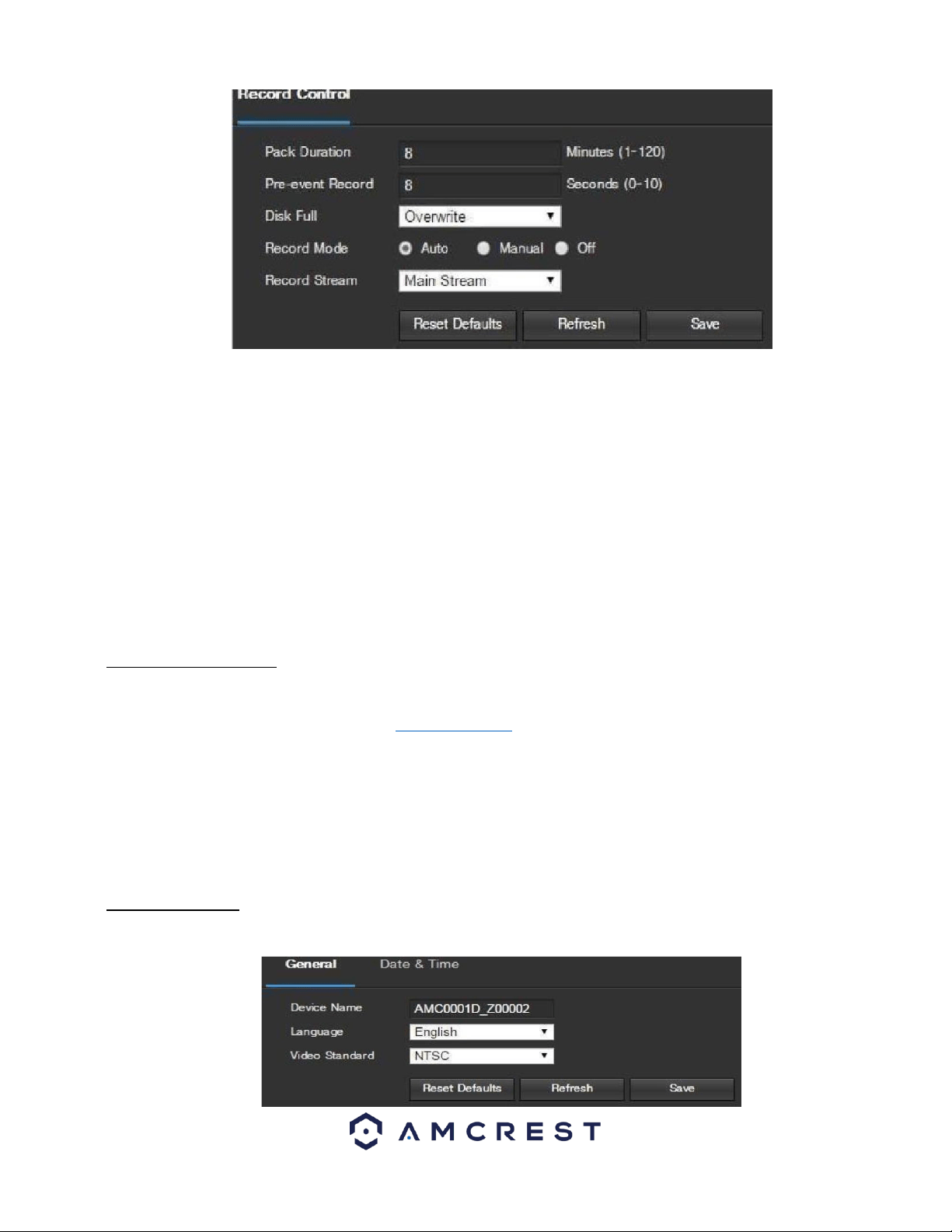
100
Below is an explanation of the fields on the Record Control settings tab:
• Pack Duration: This field allows the user to set how many minutes each file is comprised of.
• Pre-event Record: This field allows the user to specify how many seconds before an event should be recorded.
Disk Full: This dropdown box allows the user to designate what the camera should do when the disk is full. There are 2
options: Overwrite or Stop.
• Record Mode: This set of radio buttons allows the user to designate the recording mode. The options are Auto, Manual, and
Off.
Record Stream: This dropdown box allows the user to specify which stream to record. The options are main stream and sub
stream.
To reset to default settings, click the Reset Defaults button. To refresh the page, click the Refresh button. To save the
settings, click the Save button.
5.4.4.4. Cloud Storage
This menu redirects the user to the Amcrest Cloud web site. At this website (amcrestcloud.com) users can register for new
accounts as well as view or modify existing accounts.
For more information on Amcrest Cloud visit: amcrestcloud.com
5.4.5 System
This menu section allows the user to change general settings for the camera.
5.4.5.1 General
This menu controls where general settings are configured. There are 2 tabs in this menu: General and Date & Time.
5.4.5.1.1 General
This tab is where the user can configure some basic camera settings. Below is a screenshot of the General tab:
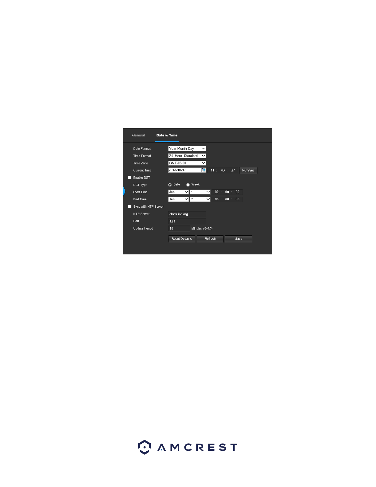
101
Below is an explanation of the fields on the General settings tab:
• Device Name: This field allows the user to change the device’s name.
• Language: This dropdown box allows the user to change the language used in the camera.
• Video Standard: This dropdown box allows the user to select either the NTSC or PAL video standard.
To reset to default settings, click the Reset Defaults button. To refresh the page, click the Refresh button. To save the
settings, click the Save button.
5.4.5.1.1 Date & Time
This tab is where the user can configure the date and time settings for the camera. Below is a screenshot of the Date & Time
tab:
Below is an explanation of the fields on the Date & Time settings tab:
• Date Format: This dropdown box allows the user to change the date format used in the camera.
• Time Format: This dropdown box allows the user to change the time format used in the camera.
• Time Zone: This dropdown box allows the user to change the time zone used in the camera.
• Current Time: This field allows the user to enter in the date and time manually. Clicking the PC Sync button allows the
camera to sync with a Network Time Protocol (NTP) server.
• Enable DST: This checkbox allows the user to enable daylight savings time for the camera.
• DST Type: This radio button allows the user to select whether DST is based on the week, or a specific day.
• Start Time: This dropdown box and field allow the user to enter in the start time for DST.
• End Time: This dropdown box and field allow the user to enter in the end time for DST.
Synchronize with NTP: This checkbox allows the user to enable the camera’s synchronization with an NTP server.
• NTP Server: This field allows the user to enter in an NTP server.
• Port: This field allows the user to enter in the port number for the NTP server.
Update Period: This field allows the user to enter in the update period time. This number designates how frequently the
camera pings the NTP server to ensure it has the correct time. The range is from 0-30 minutes.
To reset to default settings, click the Reset Defaults button. To refresh the page, click the Refresh button. To save the
settings, click the Save button.
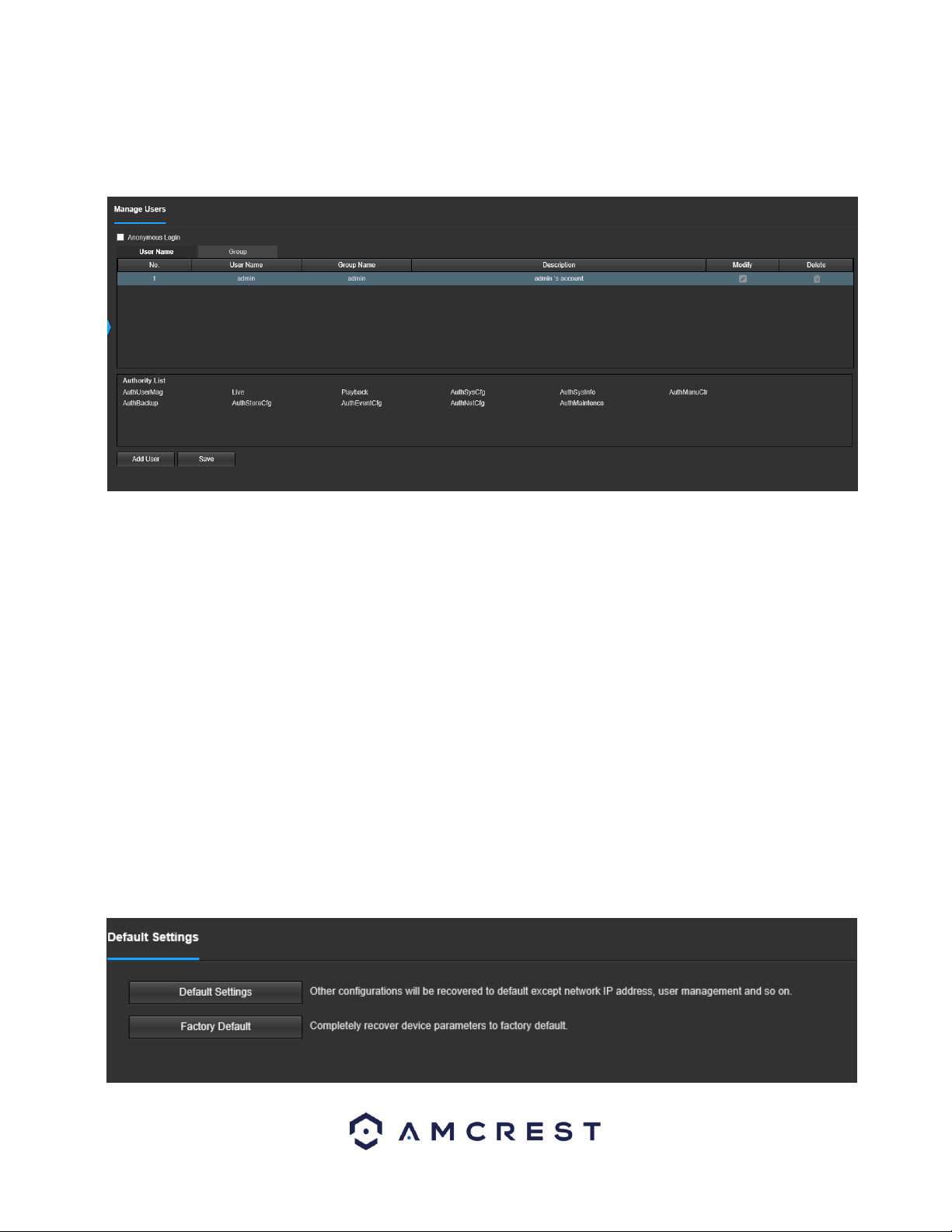
102
5.4.5.2. Manage Users
This menu allows the user to change the user accounts on the camera. By default, the camera only has the admin account
which has all rights/authorities. Additional accounts can be created on this screen. Below is a screenshot of the account
screen:
Below is an explanation of the fields on the Account screen:
• Anonymous Login: This checkbox allows the user to enable the anonymous login feature. This allows all user account names
to remain hidden on this screen.
• User Name: This tab shows the usernames available on the camera.
• Group: This tab shows the user groups available on the camera.
• No.: This column shows the user’s number on the user list.
• User Name: This column shows the usernames of the different accounts on the camera.
• Group Name: This column shows the group of the different accounts on the camera.
• Description: This column shows a description of the account.
• Modify: This column allows the user to modify the user account.
• Delete: This column allows the user to delete a user account. Note: The admin account cannot be deleted.
• Authority List: This box shows which user rights/authorities are assigned to an account.
• Add User: This button allows the user to add a new user to the camera.
5.4.5.3 Default Settings
This screen allows the user to reset the camera and all its settings to the factory settings.
Below is a screenshot of the Default screen:
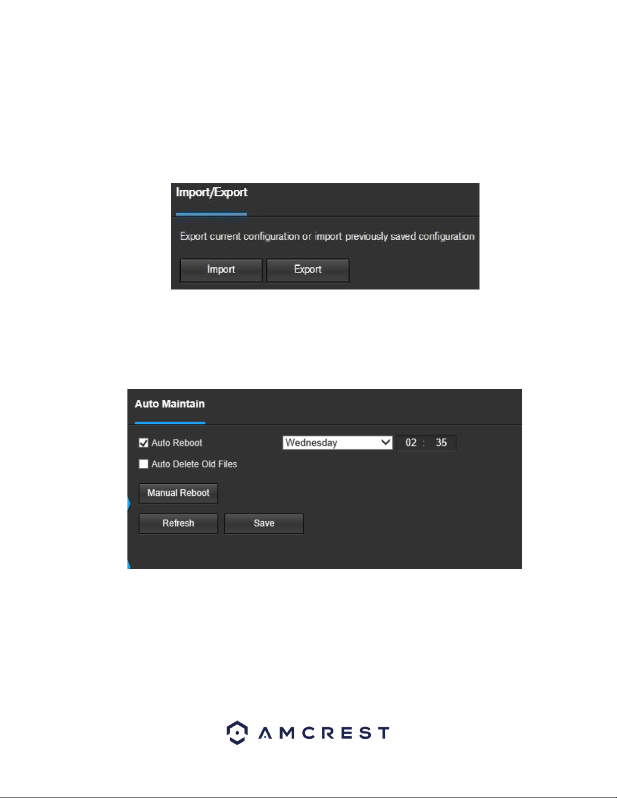
103
Below is an explanation of the items listed in this field:
Default Settings: Only the IP address, user management, and other settings can be recovered after reset.
Factory Default: Completely resets the camera to factory default settings. No settings can be recovered after the camera has
been returned to its factory default settings.
5.4.5.4 Import/Export
This screen allows the user to import or export settings from the camera. Below is a screenshot of the Import/Export screen:
To import settings, click the Import button. To export settings, click the Export button.
5.4.5.5 Auto Maintain
This screen allows the user to set auto maintenance settings for the camera. Below is a screenshot of the
Auto Maintain screen:
Below is an explanation of the fields on the Auto Maintain screen:
• Auto Reboot: This checkbox allows the user to enable the auto reboot function. The dropdown box and field to the right of
this checkbox allow the user to specify what date and time of the week the camera will auto reboot.
• Auto Delete Old Files: This checkbox allows the user to enable the auto deletion of old files on the camera.
• Manual Reboot: This button allows the user to manually reboot the camera.
To refresh the page, click the Refresh button. To save the settings, click the Save button.
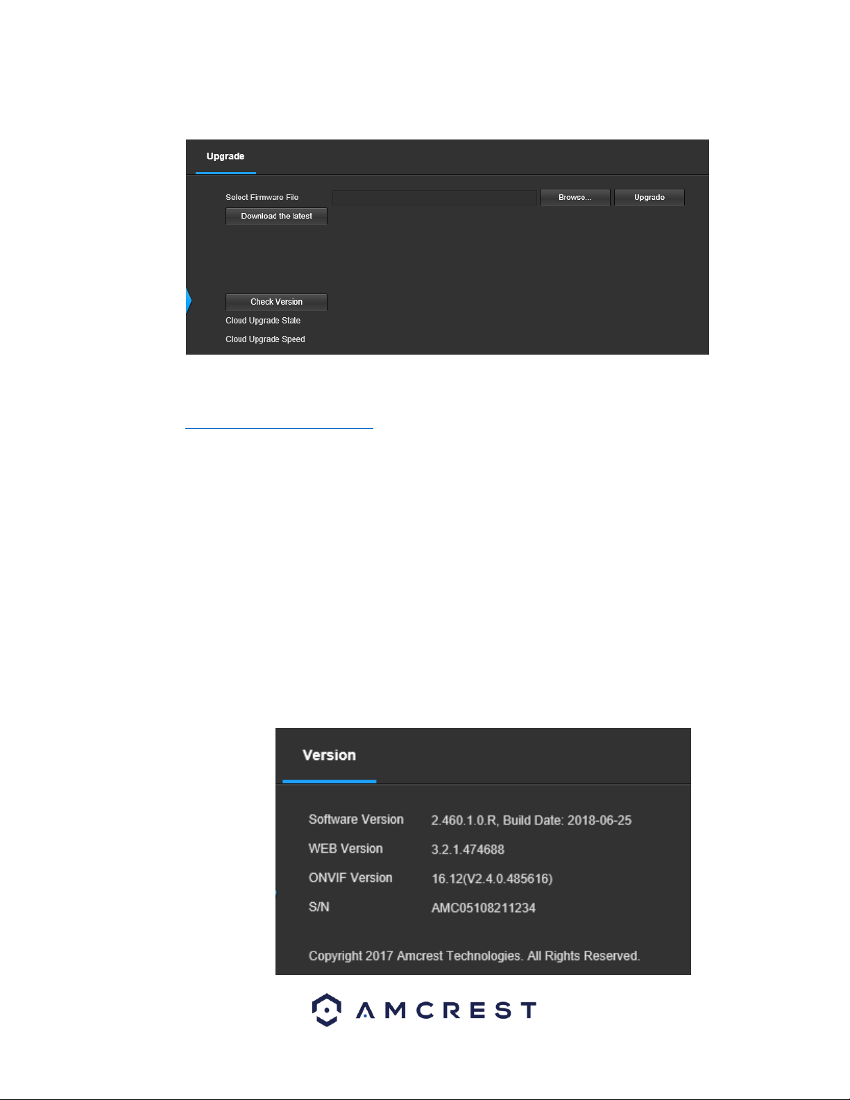
104
5.4.5.6. Upgrade
This menu allows the user to upgrade the camera’s firmware. Below is a screenshot of the Upgrade screen:
To upgrade the firmware for your camera, follow the steps provided below:
• Go to amcrest.com/firmware-subscribe
• Search for the model number of your camera and download the latest firmware file.
• Return to the web user interface for your camera and press the Browse button to locate and import the firmware
file you just downloaded.
• Once the firmware file has been imported, click Upgrade.
• The device will reset, return to the web user interface. The upgrade is now complete.
Note: When upgrading the camera’s firmware, do not disconnect the internet or power from the camera.
5.4.6 Information
This menu section allows the user to view information about the camera for reference purposes.
5.4.6.1 Version
This screen allows the user to see various information about the camera’s software versions, as well as other information.
Below is a screenshot of the camera’s version screen:
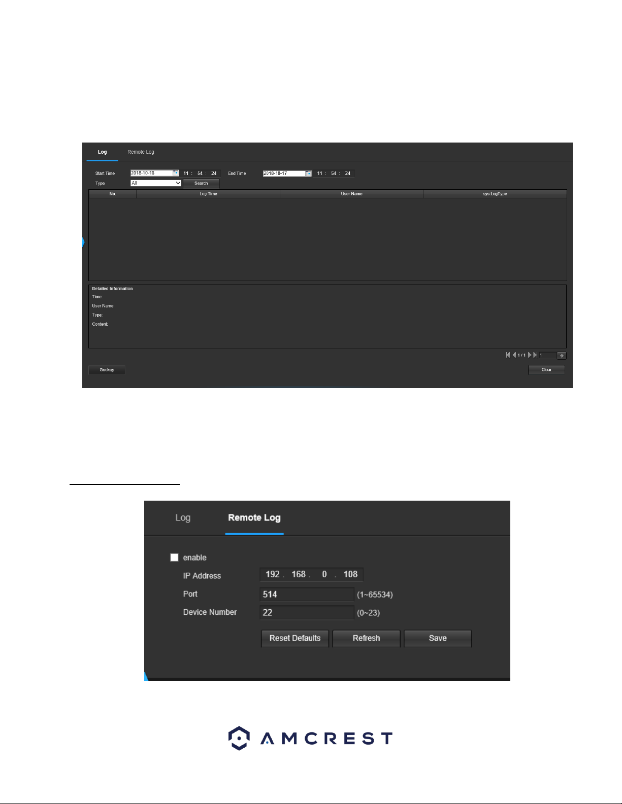
105
On this screen, software version, web interface version, and ONVIF version are displayed. Also, the S/N (Token ID) is
displayed here.
5.4.6.2 Log
This screen is where the camera’s activity log is kept. Below is a screenshot of the Log screen:
To view logs for a specific time period, modify the start time and end time fields, choose the type of event (system, setting,
data, event, record, manage users, clear log), and click search.
To backup the log, click the Backup button. To clear the log, click the Clear button.
5.4.6.2.1. Remote Log
This tab allows the user to enable and access remote logs within the camera. Below is a screenshot of this menu:
To use this menu, check the enable check box to enable remote log functionality. Enter the IP address, port number and
device number of the device you would like to pull remote logs from.
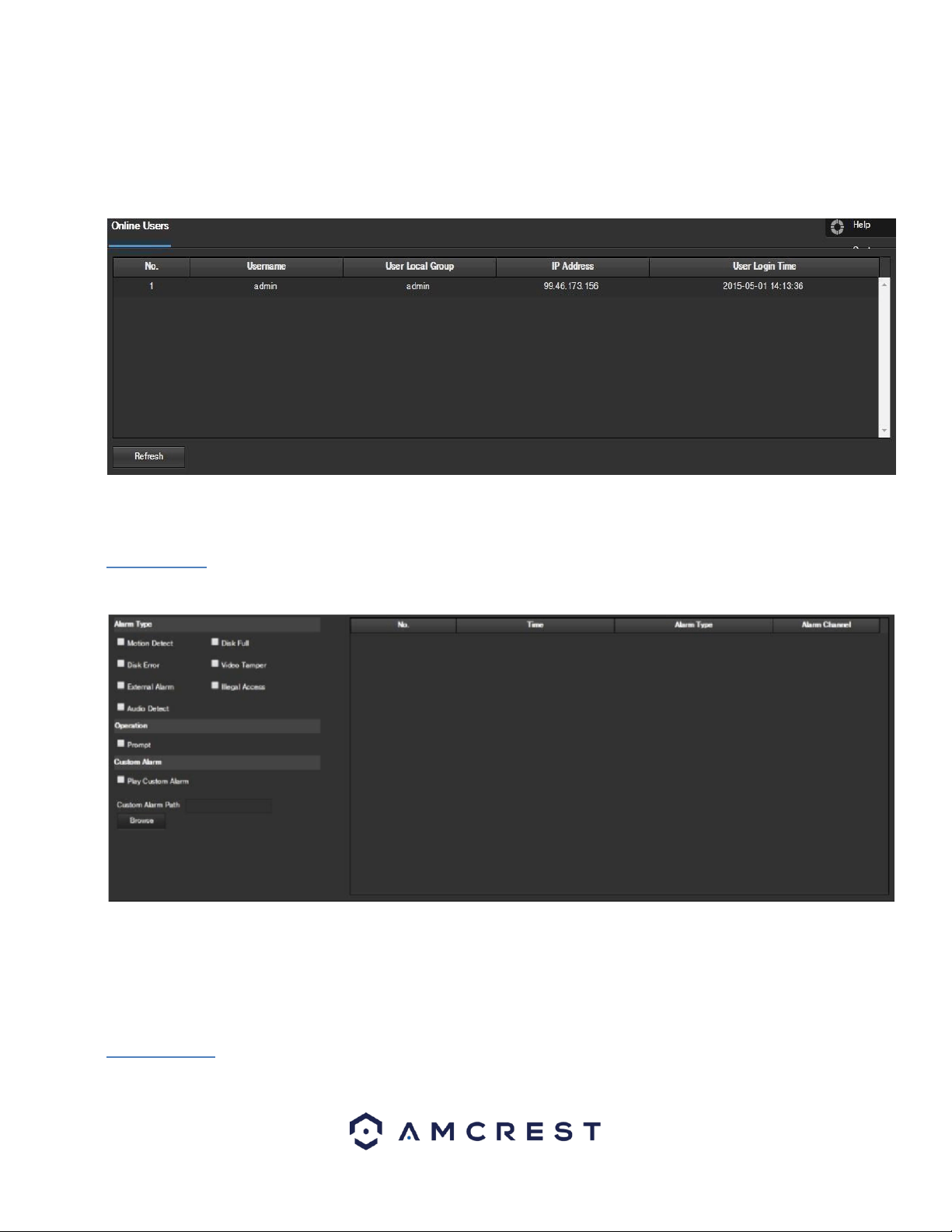
106
To save your settings, click Save. If you would like to refresh the screen to show applied settings, click Refresh. To set the
screen back to its original default settings, click Reset Defaults.
5.4.6.3 Online Users
This screen allows the user to see which users are online. Below is a screenshot of the Online Users screen:
Click Refresh to refresh this table.
5.5 Alarm
This screen is where the alarm log is kept. Below is a screenshot of the alarm screen:
The table on the right shows the alarm log and all the alarm instances that have occurred.
The checkboxes allow the user to narrow down which alarms they want to see in the alarm log. Clicking the checkbox next to
Prompt will cause the system to pop up a dialog box anytime an alarm is triggered.
Clicking the checkbox next to Play Custom Alarm will use a custom alarm sound for the alarm prompt. Click the Browse
button to search for a custom alarm sound to use.
5.6 Logout
Clicking the logout button will log out the user.

107
6. FAQs/Troubleshooting
1. The camera does not boot up properly.
Below are a few possible reasons why this may be occurring:
• The power input is not correct voltage.
• The power cable connection is not secured correctly.
• The firmware was upgraded incorrectly.
2. Camera often automatically shuts down or stops running.
Below are a few possible reasons why this may be occurring:
• The input voltage is too low or is not stable.
• The insides of the camera have accumulated too much dust.
• The temperature is either too hot or too cold.
• The hardware is malfunctioning.
3. Real-time video color is distorted.
Below are a few possible reasons why this may be occurring:
• The camera is not compatible with the monitor.
• The camera color or brightness settings are not correctly configured.
4. The timestamp is not displaying the correct time.
The time and date settings may not be configured correctly. You can take the following steps to resolve the issue:
• Log into your camera’s web user interface via a laptop or PC.
• Navigate to Setup>>System>>General
• Click on the Date & Time tab.
• Click on PC Sync to sync the date and time.
• Click Save to save and apply the new date and time settings.
5. Motion detection does not work.
Below are a few possible reasons why this may be occurring:
• The motion detection time period may be incorrectly configured.
• Motion detection zone setup is not correctly configured.
• Motion detection sensitivity is too low.
6. Web Access isn't working.
Below are a few possible reasons why this may be occurring:
• Windows version is pre -Windows 2000 service pack 4. Use a more recent version of Windows.
• ActiveX controls have been disabled.
• The PC is not using DirectX 8.1 or higher. Upgrade to a more recent version of DirectX.
• The camera is having network connection errors.
• Web access may be setup incorrectly.
• The username or password may be incorrect.
7. Web Access live view is only displaying a static picture.
Below are a few possible reasons why this may be occurring:
• The network speed is not enough to transfer video data via web access.
• The client PC may have limited resources.
• Multicast mode may be causing this issue.
• A privacy mask or screensaver may be enabled.
• The logged in user may not have enough rights to monitor real-time playback.
• The camera’s local video output quality is not enough.

108
8. Network connection is not stable.
Below are a few possible reasons why this may be occurring:
• The network is not stable.
• There may be an IP address conflict.
• There may be a MAC address conflict.
• The PC or camera network card may be defective.
• The Ethernet cable is too long
9. The alarm signal cannot be disarmed.
Below are a few possible reasons why this may be occurring:
• An alarm may be setup incorrectly.
• An alarm output may have been manually opened.
• There may be an error in the camera’s firmware.
10. Alarms are not working.
Below are a few possible reasons why this may be occurring:
• The alarm is not setup correctly.
• The alarm cable is not connected correctly.
• The alarm input signal is not correctly configured.
• There are two loops connected to one alarm device.
11. Downloaded files cannot be played back.
Below are a few possible reasons why this may be occurring:
• The media player software on the PC may not be able to read the file format.
• The PC may not have DirectX 8.1 or higher.
• The PC may not have Windows XP or higher.
12. When I login via HTTPS, a dialogue says the certificate has expired or is not valid yet.
• Ensure the PC has the same time as the camera’s system time.
Glossary of Terms
• Abnormality – Any malfunction in terms of storage of data to the SD card.
• Alarm Delay – The gap in time between alarm activation and Relay alarm activation.
• Alternate Gateway – The node on the computer network that the network software uses when an IP address does not
match any other routes in the routing table, and when the default gateway is not available.
Anti-Dither – This time value controls how long the alarm signal lasts. The values in this field can range from 5 to 600
seconds. Based on motion detection, a buzzer can go off, a tour can begin, a snapshot can be taken, or the camera can begin
recording.
• DDNS – Stands for Dynamic Domain Name System. DDNS is a method of automatically updating a name server in the
Domain Name System (DNS), often in real time, with the active DNS configuration of its configured hostnames, addresses or
other information.
• Default Gateway – The node on the computer network that the network software uses when an IP address does not match
any other routes in the routing table.
• DHCP – Dynamic Host Configuration Protocol is a network protocol that enables a server to automatically assign an IP
address to a computer from a defined range of numbers (i.e., a scope) configured for a given network.
• Fluency – Fluency described the lack of stuttering or excessive delay in a video stream. Fluency usually comes at the expense
of video quality when a network is constrained.
• IP Address – Internet Protocol Address is a unique numerical label assigned to each device connected to a computer
network. The IP address allows communication between different devices on a network.

109
• Main Stream – Main Stream is the main streaming protocol for the camera. Main stream uses more bandwidth and attempts
to keep quality and fluency high.
• NO/NC – Normally Open and Normally Closed are options for sensor type. These settings allow for different exposure types
when capturing video and still images.
• NTP – Network Time Protocol is a networking protocol for clock synchronization between computer systems over packet-
switched, variable-latency data networks.
• P2P – Peer-to-Peer is a decentralized communications model in which each party has the same capabilities and either party
can initiate a communication session.
• PPPoE – Point to Point Protocol over Ethernet is a network protocol for encapsulating Point to Point Protocol data packets
inside Ethernet frames.
• QR Code – Quick Response code is a type of digital barcode that enables devices to share complex data strings quickly.
• Record Delay – Record Delay specifies in seconds how long the delay between alarm activation and recording should be.
• Relay Out – Relay Out triggers a connected alarm (connected to the alarm port on the back of the camera) when an alarm on
the camera is triggered.
• S/N – S/N stands for serial number. The S/N is unique to each camera and can be used to connect to different Amcrest apps
and services to provide different methods of access to the camera.
• Sensitivity – Sensitivity is the amount of change required to increase the motion detected by a percentage. The lower the
sensitivity, the more movement is required to trigger an alarm.
• SMTP – Simple Main Transfer Protocol is an Internet standard for electronic mail (e-mail) transmission.
• Static IP – An IP address that does not change.
• Sub Stream – Sub Stream is an alternative streaming protocol for the camera. Sub stream uses less bandwidth and attempts
to keep fluency high at the expense of quality.
• Subnet Mask – a 32-bit number that masks an IP address, and divides the IP address into network address and host address.
• TCP/IP – TCP/IP stands for Transmission Control Protocol/Internet Protocol and it is the language/protocol that allows
communication between internet connected devices, whether on a local network, or a on the Internet at large.
• Threshold – Threshold is the level that the motion detection needs to reach to trigger an alarm.
• UPnP – UPnP stands for Universal Plug and Play, and it is a protocol used to easily connect devices to the internet.
• Video Tamper – Video Tamper refers to any major changes happening to the video feed such as it being blocked out,
interfered with, or disconnected.

110
FCC Statement
1. This device complies with Part 15 of the FCC Rules. Operation is subject to the following two conditions: (1) this
device may not cause harmful interference, and (2) this device must accept any interference received, including interference
that may cause undesired operation.
2. The user’s manual or instruction manual for an intentional or unintentional radiator shall caution the user that
changes, or modifications not expressly approved by the party responsible for compliance could void the user's authority to
operate the equipment. In cases where the manual is provided only in a form other than paper, such as on a computer disk
or over the Internet, the information required by this section may be included in the manual in that alternative form,
provided the user can reasonably be expected to have the capability to access information in that form.
3. (b) For a Class B digital device or peripheral, the instructions furnished the user shall include the following or similar
statement, placed in a prominent location in the text of the manual: NOTE: This equipment has been tested and found to
comply with the limits for a Class B digital device, pursuant to Part 15 of the FCC Rules. These limits are designed to provide
reasonable protection against harmful interference in a residential installation. This equipment generates, uses and can
radiate radio frequency energy and, if not installed and used in accordance with the instructions, may cause harmful
interference to radio communications. However, there is no guarantee that interference will not occur in a particular
installation. If this equipment does cause harmful interference to radio or
television reception, which can be determined by turning the equipment off and on, the user is encouraged to try to correct
the interference by one or more of the following measures: -- Reorient or relocate the receiving antenna. -- Increase
the separation between the equipment and receiver. -- Connect the equipment into an outlet on a circuit different from
that to which the receiver is connected. -- Consult the dealer or an experienced radio/TV technician for help.
4. RF exposure warning This equipment must be installed and operated in accordance with provided instructions
and the antenna(s) used for this transmitter must be installed to provide a separation distance of at least 20 cm from all
persons and must not be co-located or operating in conjunction with any other antenna or transmitter.
End-users and installers must be provided with antenna installation instructions and transmitter operating conditions for
satisfying RF exposure compliance.
IC Warning Statement
TThis device complies with Industry Canada’s licence-exempt RSSs. Operation is subject to the following two conditions: (1)
This device may not cause interference; and (2) This device must accept any interference, including interference that may
cause undesired operation of the device. Le présent appareil est conforme aux CNR d'Industrie Canada applicables aux
appareils radio exempts de licence. L'exploitation est autorisée aux deux conditions suivantes : (1) l'appareil ne doit pas
produire de brouillage, et (2) l'utilisateur de l'appareil doit accepter tout brouillage radioélectrique subi, même si le
brouillage est susceptible d'en compromettre le fonctionnement. This equipment complies with IC RSS-102 radiation
exposure limits set forth for an uncontrolled environment. This equipment should be installed and operated with a
minimum distance of 20cm between the radiator and any part of your body. Pour se conformer aux exigences de
conformité CNR 102 RF exposition, une distance de séparation d'au moins 20 cm doit être maintenue entre l'antenne de cet
appareil ettoutes les personnes.

111
Appendix A: Toxic or Hazardous Materials or Elements
Component
Name
Toxic or Hazardous Materials or Elements
Pb
Hg
Cd
Cr VI
PBB
PBDE
Sheet
Metal(Case)
○
○
○
○
○
○
Plastic Parts
(Panel)
○
○
○
○
○
○
Circuit Board
○
○
○
○
○
○
Fastener
○
○
○
○
○
○
Wire and
Cable/Ac
Adapter
○
○
○
○
○
○
Packing
Material
○
○
○
○
○
○
Accessories
○
○
○
○
○
○
O: Indicates that the concentration of the hazardous substance in all homogeneous materials in the parts is below the
relevant threshold of the SJ/T11363-2006 standard.
X: Indicates that the concentration of the hazardous substance of at least one of all homogeneous materials in the parts is
above the relevant threshold of the SJ/T11363-2006 standard. During the environmental-friendly use period (EFUP) period,
the toxic or hazardous substance or elements contained in products will not leak or mutate so that the use of these
(substances or elements) will not result in any severe environmental pollution, any bodily injury or damage to any assets.
The consumer is not authorized to process such kind of substances or elements, please return to the corresponding local
authorities to process according to your local government statutes.
O: Indicates that the concentration of the hazardous substance in all homogeneous materials in the parts is below the
relevant threshold of the SJ/T11363-2006 standard.

112
X: Indicates that the concentration of the hazardous substance of at least one of all homogeneous materials in the parts is
above the relevant threshold of the SJ/T11363-2006 standard. During the environmental-friendly use period (EFUP) period,
the toxic or hazardous substance or elements contained in products will not leak or mutate so that the use of these
(substances or elements) will not result in any severe environmental pollution, any bodily injury or damage to any assets.
The consumer is not authorized to process such kind of substances or elements, please return to the corresponding local
authorities to process according to your local government statutes.
Note:
• To view setup videos for many of the steps outlined in this guide, go to http://amcrest.com/videos
• This user manual is for reference only. Slight differences may be found in the user interface.
• All the designs and software here are subject to change without prior written notice.
• All trademarks and registered trademarks mentioned are the properties of their respective owners.
To contact Amcrest support, please do one of the following:
Visit http://amcrest.com/contacts and use the email form
Call Amcrest Support using one of the following numbers Toll Free US: (888) 212-7538
International Callers (Outside of US): +1-713-893-8956
USA: 713-893-8956
Canada: 437-888-0177
UK: 203-769-2757
Email Amcrest Customer Support [email protected]m
Copyright Amcrest
©
2019