Loading ...
Loading ...
INSTALLATION INSTRUCTIONS
NOTE: MAKE SURE YOU REMOVE ALL CONTENTS FROM
THE PACKAGE. PLEASE CHECK PACKAGING MATERIALS FOR
PARTS THAT COULD BE REQUIRED TO OPERATE YOUR FAN.
The window fan comes fully assembled and is ready for
immediate installation (with the Slider Safe Extender
separately packed in the box).
This window fan has been designed to fit double-hung
windows with minimum openings of 25.5 inches (65cm)
wide and 8 inches (20cm) high.
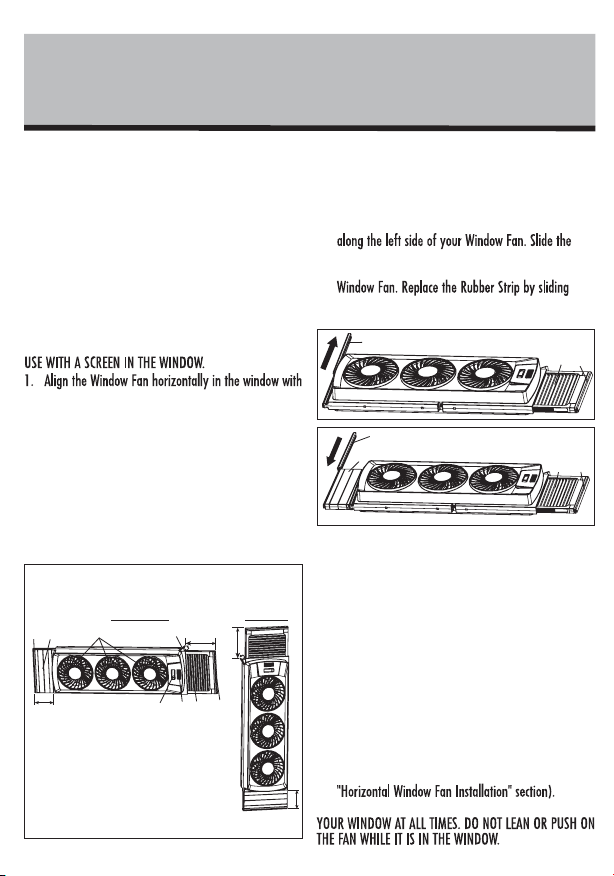
Horizontal Window Fan Installation
NOTE: THIS FAN IS DESIGNED AND RECOMMENDED FOR
the controls facing you and the power cord located on
the bottom of the window fan.
2. Set the fan into your window opening (note that in
most cases the window screen does not have to be
removed or left open).
3. If the fan does not fit snugly to the left and right of
the window casing, open the Locking Tab (D) by
pulling up and pull out the Built-In Extender Panel
(F) until the fan sits safely in your window. Re-lock or
close the locking tab after the fan is safely secured in
the window.
4. If the fan still does not fit snugly attach the Slider
Safe
®
Extender Panel located in the polyfoam
packaging in the original box. The fan can extend to
a width of 6.7-8.7 inches (17-22cm). Slide out the
Rubber Strip (A) from the left side of the fan - see
Figure 2. Then slide the Slider Safe
®
Extender Panel
Slider Safe
®
Extender Panel completely down the tab
until it is flush on both the top and bottom of the
down along the left side of the added Slider Safe
®
Extender Panel - see Figure 3.
5. To keep the fan in place, carefully close the window
so that the bottom edge of the window gently rests
on the flat area on the top of the fan.
Vertical Window Fan Installation
1. For vertical orientation, install unit using rigid
extender panels at the base of window.
2. Set the Fan vertically in your window opening with
the left side of the fan situated on the bottom and
the Built-In Extender Panel on top.
3. Set the fan into your window opening (note that in
most cases the window screen does not have to be
removed or left open).
4. If the fan does not fit snugly to the top and bottom
of the window casing, attach the Slider Safe
®
Extender Panel and adjust the built-in extender
screen until the fan fits securely in your window (see
WARNING: BE SURE FAN IS SECURELY INSTALLED IN
PLE AS E READ AN D SAVE T HESE
I M P O RTANT S AFE T Y INSTR UC TI ON S
F E AT U RES - O P E R ATI ON S
F E AT U RES - O P E R ATION S
CLE AN I N G / M A IN T E N ANCE
should always be taken including the following:
1. Read all instructions before using this appliance.
2. Use fan only for purposes described in the instruction
manual.
3. To protect against electrical shock do not immerse
unit, plug or cord in water or spray with liquids and
plug the appliance directly into a 120V AC electrical
outlet.
4. Close supervision is necessary when any appliance is
used by or near children.
5. Unplug from outlet when not in use, when moving
fan from one location to another, before putting on
or taking off parts and before cleaning.
6. Avoid contact with moving parts.
7. Do not operate in the presence of explosive and/or
flammable fumes.
8. To avoid fire hazard, NEVER place the cord under
rugs or any parts near an open flame, cooking or
other heating appliance.
9. Do not operate any appliance with a damaged cord
or plug after the appliance malfunctions, or has been
dropped/damaged in any manner. Discard fan or
return to an authorized service facility for
examination and/or repair.
10. Do not run cord under carpeting. Do not cover cord
with throw rugs, runner, or similar coverings. Do not
route cord under furniture or appliances. Arrange
cord away from traffic area and where it will not be
tripped over.
11. The use of attachments not recommended or sold by
the appliance manufacturer may cause hazards.
12. Do not let the cord hang over the edge of a table,
counter or come in contact with hot surfaces or leave
exposed to high traffic areas.
13. Do not use outdoors.
14. To disconnect, grip plug and pull from wall outlet.
Never yank on cord.
15. Always use on a dry, level surface.
16. Do not operate fan until fully assembled with all
parts properly in place.
17. This product is intended for household use ONLY and
not for commercial or industrial applications.
18. WARNING: To reduce the risk of fire or electric
shock, do not use this fan with any solid-state speed
control device.
19. This product employs overload protection (fuse). A
blown fuse indicates an overload or short-circuit
situation. If the fuse blows, unplug the product from
the outlet. Replace the fuse as per the user servicing
instructions (follow product marking for proper fuse
rating) and check the product. If the replacement
fuse blows, a short circuit may be present and the
product should be discarded or returned to an
authorized service facility for examination and/or
repair.
20. Do not use an extension cord with this fan.
21. For general ventilating use only. Do not use to
exhaust hazardous or explosive materials and
vapors.
PLEASE READ AND SAVE
THESE IMPORTANT
SAFETY INSTRUCTIONS
OPERATING INSTRUCTIONS
)
position.
around in the window. (Controls can be operated
from both sides.)
number of fan blades in operation (see the close-up
of the control panel below).
NOTE: If you would like the fan to run
continuously, turn the Comfort Control
Thermostat dial up to High (Warm) as far as it
will go.
COMFORT CONTROL THERMOSTAT
INSTRUCTIONS
Your window fan is equipped with a Comfort Control
Thermostat that automatically turns the fan on and off
depending on your preset comfort level.
1. For the fan to turn on, the
thermostat must be set at a
temperature lower than the
current room temperature. If the
fan power is on but the fan
blades (C) aren’t moving, turn the
Comfort Control Thermostat (G)
fan blades (C) spin.
2. To set your desired comfort level,
run the fan until the temperature in your room is
comfortable. Slowly turn the Comfort Control
Thermostat dial down to Low (Cool) until the fan
blades turn off. This is the temperature your fan will
maintain.
NOTE: If you would like the fan to run
continuously, turn the Comfort Control
Thermostat dial up to High (Warm) as far as it
will go.
CLEANING/MAINTENANCE
INSTRUCTIONS
Follow these instructions to correctly and safely care for
your window fan. Please remember:
REPLACEABLE FUSE
If your (5 Amp, 125 Volt) replaceable fuse blows, please
order a new fuse at 1-800-253-2764. Follow the below
instructions to replace the fuse on the plug.
User Servicing Instructions
1. Unplug your fan. Grasp plug and remove from the
receptacle or other outlet device. Do not unplug by
pulling on cord.
2. Open fuse cover, located on the top of the plug, by
using your thumb or a flathead screwdriver to slide
the cover down towards the prongs.
NOTE: Ensure that fuse cover is completely open
before attempting to remove fuse.
3. Remove fuse carefully by
using a small screwdriver
to pry the fuse out of the
compartment by the metal
ends of the fuse. (see
Figure 4)
4. Place plug on a solid, flat
surface. Insert new 5
Amp, 125 Volt fuse into
fuse compartment and use a small screwdriver to
secure the metal ends of the fuse into the
compartment.
CAUTION: Risk of fire. Replace fuse only with 5
Amp, 125 Volt fuse.
5. Slide fuse cover closed completely. If fuse cover is
difficult to close, make sure fuse is secured in place
completely by pressing down on metal ends of the fuse.
6. Risk of fire. Do not replace attachment plug. Contains
a safety device (fuse) that should not be removed.
Discard product if the attachment plug is damaged.
THIS APPLIANCE HAS A POLARIZED PLUG (one blade is wider than the
other). To reduce the risk of electric shock, this plug is intended to fit in
a polarized outlet only one way. If the plug does not fit fully in the
outlet, reverse the plug. If it still does not fit, contact a qualified
electrician to install the proper outlet.
DO NOT ATTEMPT TO MODIFY THIS PLUG OR DEFEAT THIS
SAFETY FEATURE IN ANY WAY.
Figure 4
Fuse
Metal ends
Fuse cover
Figure 2
A
F
E
Figure 3
A
B
F
E
6cm
17cm
6cm
17
cm
Figure 1 *Total extendable width:
36.7 inches (93.2cm)
A. Rubber Strip
B. Slider Safe
®
Extender Panel
C. Fan Blades
D. Locking Tab
E. Adjustable Extruded Gasket
F. Built-in Extender Panel
G. Thermostat Control
A
D
H
G
F
C
B
E
H. Power Switch
Horizontal
Vertical
Loading ...
Loading ...
Loading ...