CE244DTB1, CE304DTB1 & CE365DTB1 Models
CERAMIC COOKTOP
INSTALLATION GUIDE
US CA
592141A 05.20
2
SAFETY AND WARNINGS
!
WARNING!
Electric Shock Hazard
Failure to follow this advice may result in
electric shock or death.
• Disconnect the appliance from the mains
electricity supply before carrying out any work or
maintenance.
• Connection to a good earth wiring system is
essential and mandatory.
• Alterations to the domestic wiring system must
only be made by a qualified electrician.
!
WARNING!
Cut Hazard
Failure to use caution could result in injury.
• Take care: some edges are sharp.
READ AND SAVE THIS GUIDE
General Use
z
Read these instructions carefully before installing this product.
z
Save these instructions for the local electrical inspector’s use.
z
Installation must comply with your local building and local electricity regulations.
z
Electrical installation (including electrical grounding) must be done in accordance
with the National Electrical Code, ANSI/NFPA70 – latest edition and/or local codes. In
Canada: Electrical installation must be in accordance with the current CSA C22.1 Canadian
Electrical Codes Part 1 and/or local codes. Particular attention shall be given to the
relevant requirements regarding ventilation.
z
This appliance is to be installed and serviced only by fisher & Paykel trained and
supported service technician or qualified person.
z
The manufacturer accepts no responsibility for the incorrect installation of appliances.
Incorrect installation may result in personal injury, damage to property and may invalidate
any warranty or liability claims.
z
Do not modify this appliance.
z
Do not use or store flammable materials on or near this appliance.
z
Packing elements (eg plastic bags, polystyrene foam, staples, packing straps etc) and
tools should not be left around during and after installation, especially if they are within
easy reach of children, as these may cause serious injuries.
z
Make sure you recycle the packaging material.
z
Before disposing of any appliance, make sure that it can no longer be used and that all
hazardous parts are removed or made harmless, so that children playing with the old
appliance cannot harm themselves.
z
Only genuine replacement parts may be used for servicing the appliance. These are
available from your nearest Fisher & Paykel Service Center.
z
This cooktop requires adequate supply of cool air to fully function. The base of the
cooktop must have direct unrestricted ventilation to the room where the cooktop is
installed. There must be a 5mm air gap at the front of the cooktop as shown on diagram
above in ‘Venting Clearances’. Follow the requirements shown.
z
This cooktop must be connected to the mains power supply only by a suitably
qualified person.
z
To connect the cooktop to the mains power supply, do not use adapters, reducers, or
branching devices, as they can cause overheating and fire.
z
The power supply cable must not touch any hot parts and must be positioned so that its
temperature will not exceed 165°F (75°C) at any point.

3
INSTALLATION CONSIDERATIONS
Before you install the appliance, please ensure the following:
z
The countertop is made of a heat resistant material.
z
The power supply cable is not accessible through cupboard doors or drawers.
z
There is adequate flow of cool air from the cabinetry to the base of the cooktop. You
may ventilate from adjacent cupboards, but ensure that the available air supply will not
be restricted.
z
The ventilation area must be at least two 2" (50mm) diameter holes or of an
equivalent area.
z
You use heat-resistant and easy-to-clean finishes (such as ceramic tiles) for the wall
surfaces surrounding the cooktop.
z
The cooktop will not be installed directly above a dishwasher, fridge, freezer, washing
machine or clothes dryer, as the humidity may damage the cooktop electronics.
z
If the cooktop is installed above an oven, the oven has a built-in cooling fan.
z
The installation will comply with all clearance requirements and applicable standards and
regulations.
z
You consult local building authorities and by-laws if in doubt regarding installation.
z
To eliminate the risk of burns or fire by reaching over heated surface units, cabinet storage
space located above the surface units should be avoided. If cabinet storage is to be
provided, the risk can be reduced by installing a rangehood that projects horizontally a
minimum of 5" (127mm) beyond the bottom of the overhead cabinets.
When you install the appliance
z
Seal exposed bare edges of the cutout with an oil-based paint or moisture-proof
polyurethane to prevent possible moisture creeping between the cooktop trim and
the countertop.
z
Take extreme care not to chip, crack, or break the top glass surfaces during installation.
A heavy metal tool or part accidentally dropped on the glass could damage it.
z
If, after following the instructions given, correct performance cannot be achieved, please
contact your nearest Fisher & Paykel Service Centre, Customer Care, or contact us through
our local website listed at the end of this document.
PARTS SUPPLIED
Clamping brackets (4)
and screws (4)
Foam tape (1)
4
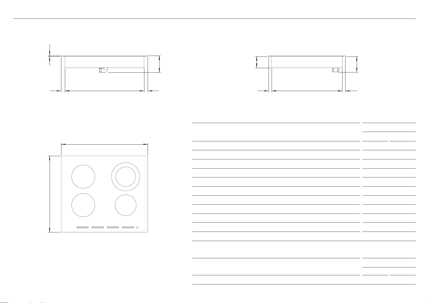
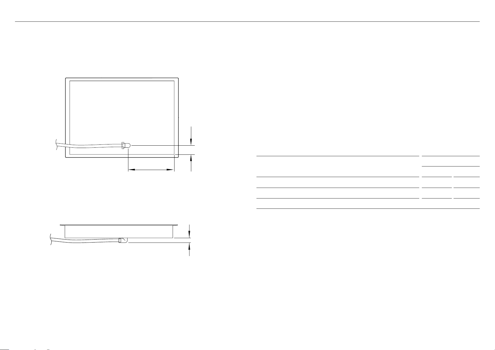
PRODUCT DIMENSIONS
CE244DTB1
INCHES MM
A Overall height of the cooktop 4 1/2 115
B Overall width of cooktop 23 5/8 600
C Overall depth of cooktop 20 7/8 530
D Height of cooktop surface 3/16 5
E Height of chassis
(incl. height of conduit junction)
4 5/16 110
F Height of the chassis
(below glass excl. height of conduit junction) 3 1/8 79.5
G Width of chassis 21 5/8 549
H Depth of chassis 19 5/16 490
I Depth of front overhang of cooktop surface 13/16 20
J Depth of rear overhang of cooktop surface 13/16 20
K Depth of side overhang of cooktop surface 1 26
PROFILE
PRODUCT DIMENSIONS — 24" MODEL
Actual product dimensions may vary by ± 2 mm.
PLAN
b
c
i
e
h j
FRONT
A
d
k
k g
PRODUCT WEIGHT
CE244DTB1
LB KG
Weight of the product (excluding packaging) 30.9 14
Refer to ‘Electrical Dimensions’ for details conduit dimension.
f
5
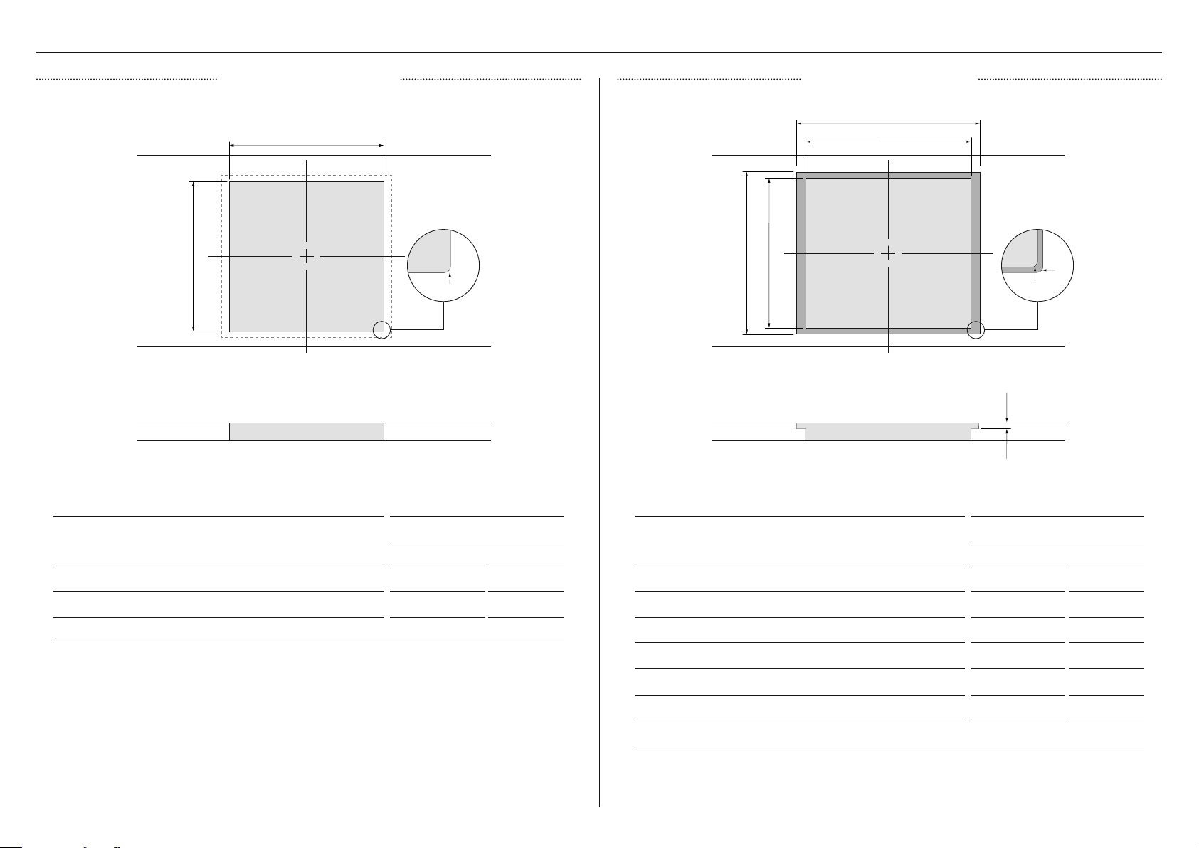
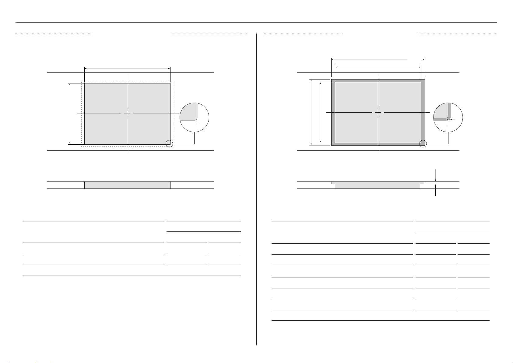
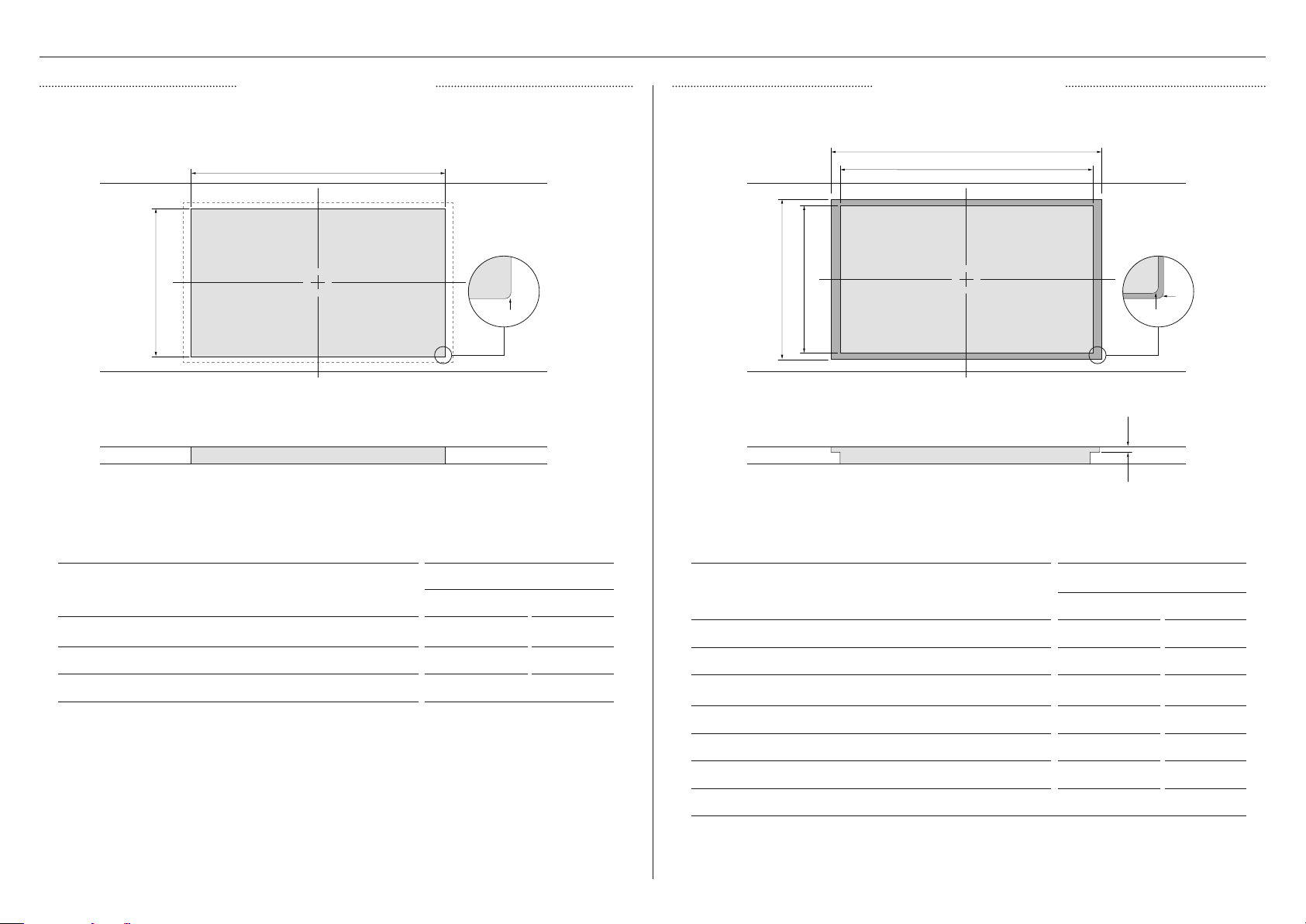
CUTOUT DIMENSIONS — 24" MODEL
CUTOUT DIMENSIONS
CE244DTB1
INCHES MM
A Width of cutout 21 7/8 555
B Depth of cutout 19 1/2 495
C Corner radius of cutout max. 5/16 8
FLUSH MOUNTING CUTOUT DIMENSIONS
CE244DTB1
INCHES MM
A Overall width of routered recess 23 13/16 605
B Width of cutout 21 7/8 555
C Depth of cutout 19 1/2 495
D Overall depth of routered recess 21 1/16 535
E Height of routered recess 3/16 5
F Corner radius of routered recess 3/16 5
G Corner radius of cutout max. 5/16 8
PROUD INSTALLATION FLUSH INSTALLATION
PLAN PLAN
FRONT FRONT
a
c
b
a
b
d
c
e
f
g
6
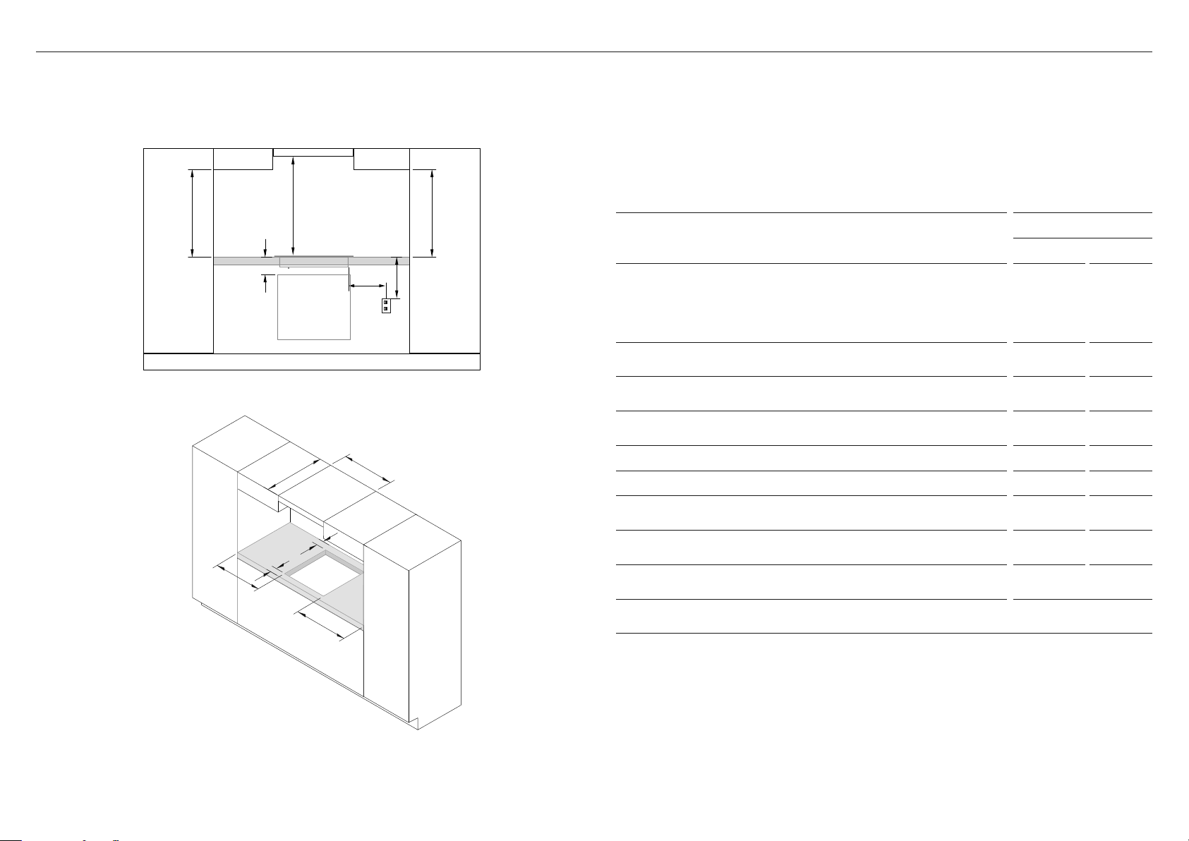
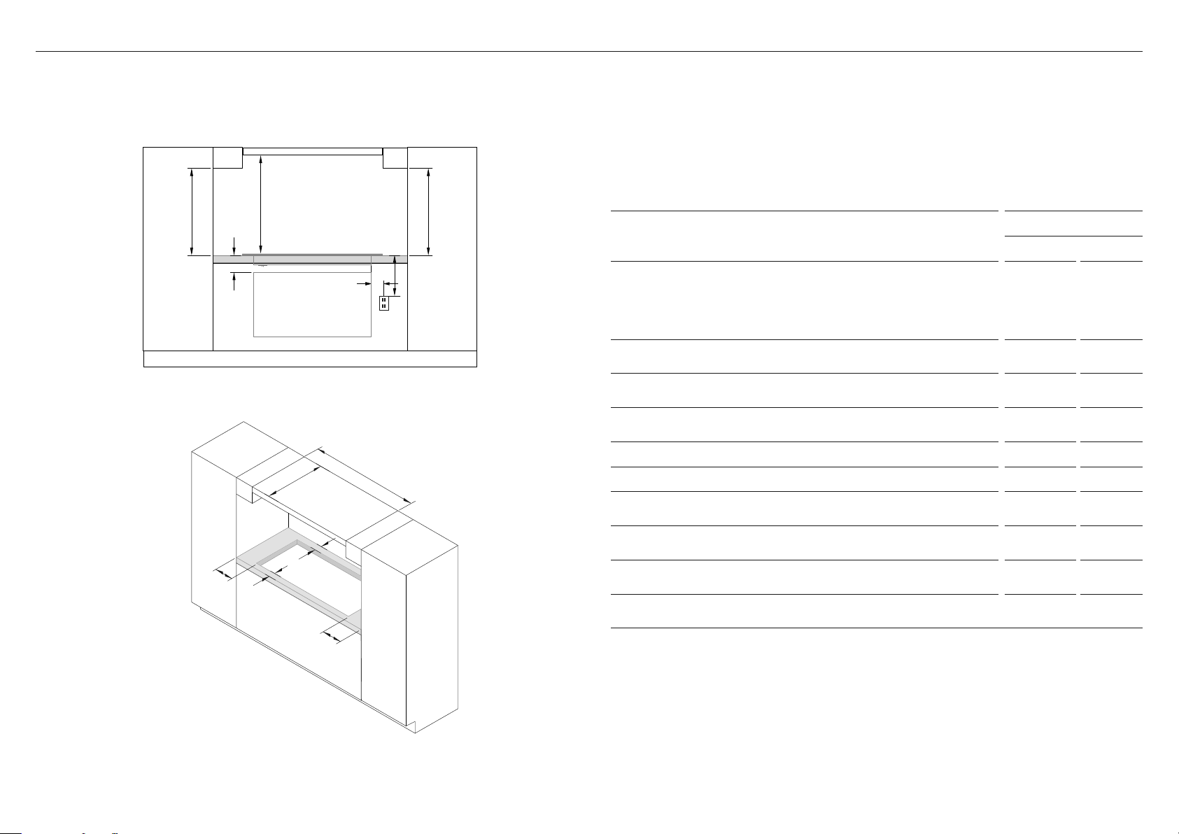
CLEARANCE DIMENSIONS — 24" MODEL
a
b
c
c
d
e
f
g
h
i
jj
Combustible surface
Any materials of a building structure or decorative structure made of wood, compressed
paper, plant fibres, vinyl/plastic or other materials that are capable of transferring heat or
being ignited and burned. Such material shall be considered combustible even though flame-
proofed, fire-retardant treated or surface-painted, or plastered.
CLEARANCE DIMENSIONS
CE244DTB1
INCHES MM
A Minimum clearance from ceramic surface to overhead cabinet
centered above cooktop:
z
Minimum clearance from ceramic surface to rangehood†
z
Unprotected*
+
z
Protected*
+
25 9/16
30
24
650
762
610
B Minimum clearance below top of countertop to top of any
appliance, companion product or obstruction below cooktop
4 1/2 115
C Minimum clearance from side edges of cutout to nearest
combustible surface
2 3/16 55
D Maximum clearance from right edge of cutout to center of
junction box
30 762
E Minimum clearance below top of countertop to junction box 9 1/16 230
F Maximum depth of overhead cabinetry 13 330
G Minimum clearance between overhead cabinets either side of
the cooktop
24 3/16 615
H Minimum clearance from rear edge of cutout to nearest
combustible surface
2 3/16 55
I
Minimum clearance from front edge of cutout to front edge
of counter
1 3/8 35
J Minimum clearance from countertop to overhead cabinet not
directly above the cooktop
17 11/16 450
*To eliminate the risk of burns or fire by reaching over heated surface units, cabinet storage space
located above the surface units should be avoided. If cabinet storage is to be provided, the risk can
be reduced by installing a rangehood that projects horizontally a minimum of 5" (127mm) beyond the
bottom of the cabinets.
+
A=30" (762mm) minimum clearance between the top of the cooking surface and the bottom of an
unprotected wood or metal cabinet; or
A=24" (610mm) minimum when bottom of wood or metal
cabinet is protected by not less than ¼"-thick flame-retardant millboard covered with not less than
No. 28 MSG sheet steel, 0.015"-thick stainless steel, 0.024"-thick aluminum, or 0.020"-thick copper.
†Refer to your range hood installation guide for further details on clearances.
7
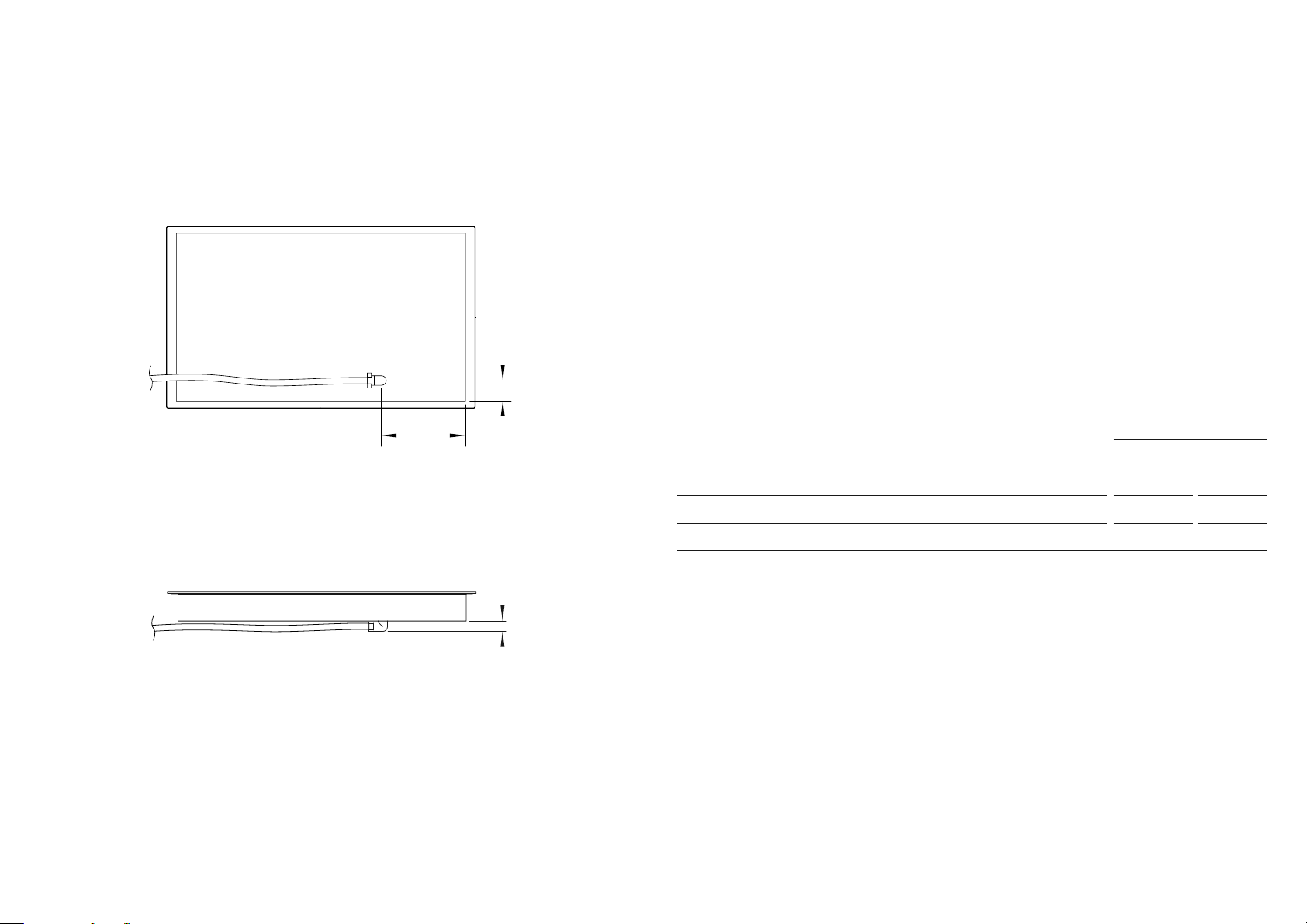
ELECTRICAL DIMENSIONS — 24" MODEL
FRONT
BOTTOM
a
B
C
ELECTRICAL DIMENSIONS
CE244DTB1
INCHES MM
A Distance to center of conduit junction from right side of chassis 9/16 24
B Distance to center of conduit junction from rear of chassis 1 7/ 8 47
C Max height of conduit junction from bottom of chassis 11/4 31
8
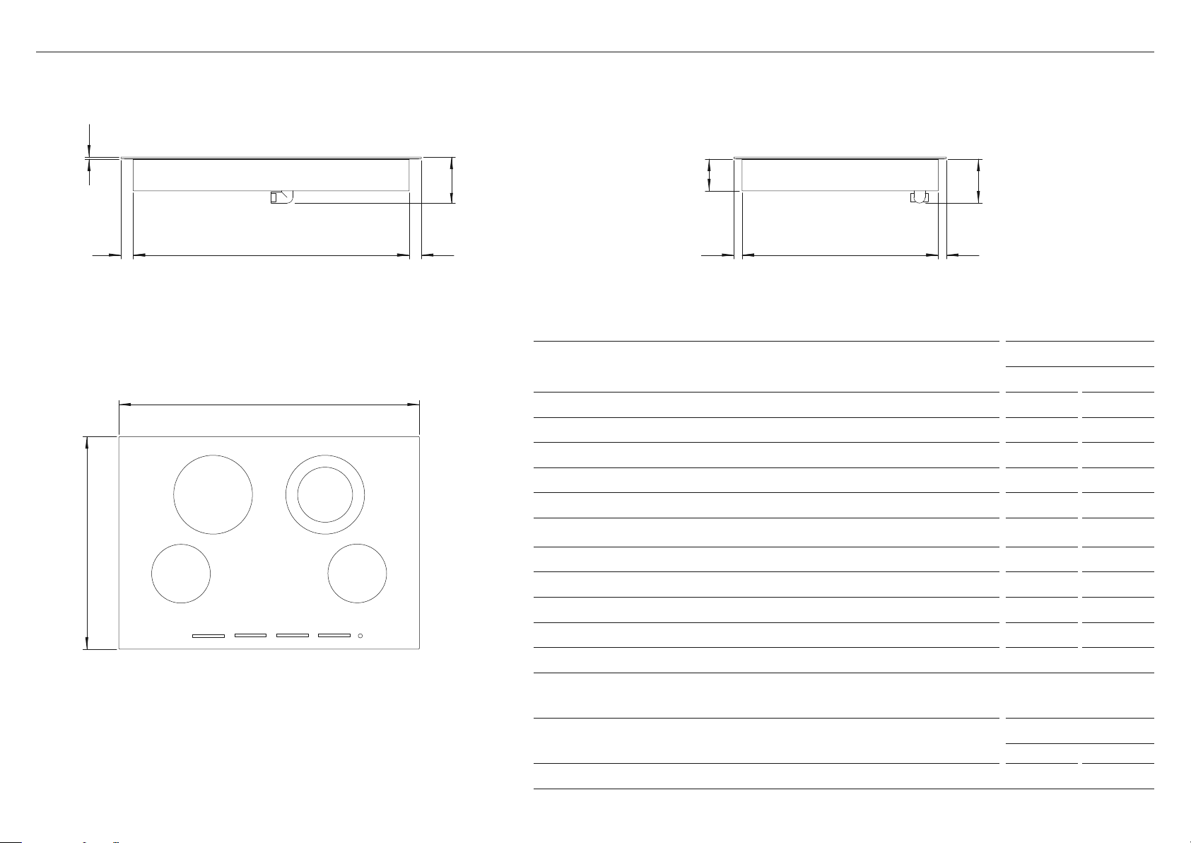
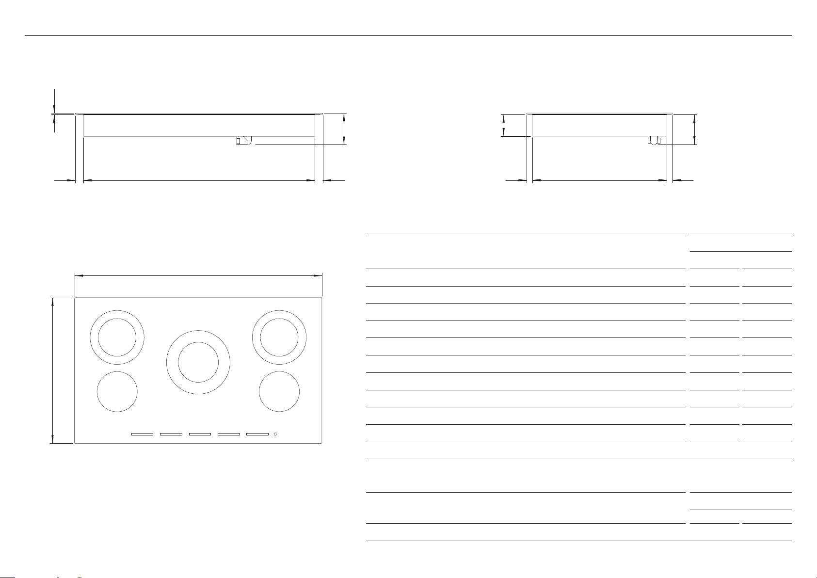
PRODUCT DIMENSIONS — 30" MODEL
PRODUCT DIMENSIONS
CE304DTB1
INCHES MM
A Overall height of the cooktop 4 1/2 115
B Overall width of cooktop 29 1/2 750
C Overall depth of cooktop 20 7/8 530
D Height of the cooktop surface 3/16 5
E Height of chassis
(incl. height of conduit junction)
4 5/16 110
F Height of the chassis
(below glass excl. height of conduit junction) 3 1/8 79.5
G Width of chassis 27 1/8 689
H Depth of chassis 19 5/16 490
I Depth of front overhang of cooktop surface 13/16 20
J Depth of rear overhang of cooktop surface 13/16 20
K Depth of side overhang of cooktop surface 1 1/4 31
Actual product dimensions may vary by ± 2 mm.
PRODUCT WEIGHT
CD304DTB1
LB KG
Weight of the product (excluding packaging) 35 16
Refer to ‘Electrical Dimensions’ for details conduit dimension.
FRONT
PLAN
PROFILE
j
d
A
kk
e
h
i
b
c
g
f
9
FLUSH MOUNTING CUTOUT DIMENSIONS
CE304DTB1
INCHES MM
A Overall width of routered recess 29 3/4 755
B Width of cutout 27 9/16 700
C Depth of cutout 19 1/2 495
D Overall depth of routered recess 21 1/16 535
E Height of routered recess 3/16 5
F Corner radius of routered recess 3/16 5
G Corner radius of cutout max. 3/8 10
CUTOUT DIMENSIONS — 30" MODEL
FRONT FRONT
PLAN
PLAN
a
b
c
a
b
cd
e
f
CUTOUT DIMENSIONS
CE304DTB1
INCHES MM
A Width of cutout 27 9/16 700
B Depth of cutout 19 1/2 495
C Corner radius of cutout max. 3/8 10
g
PROUD INSTALLATION FLUSH INSTALLATION
10
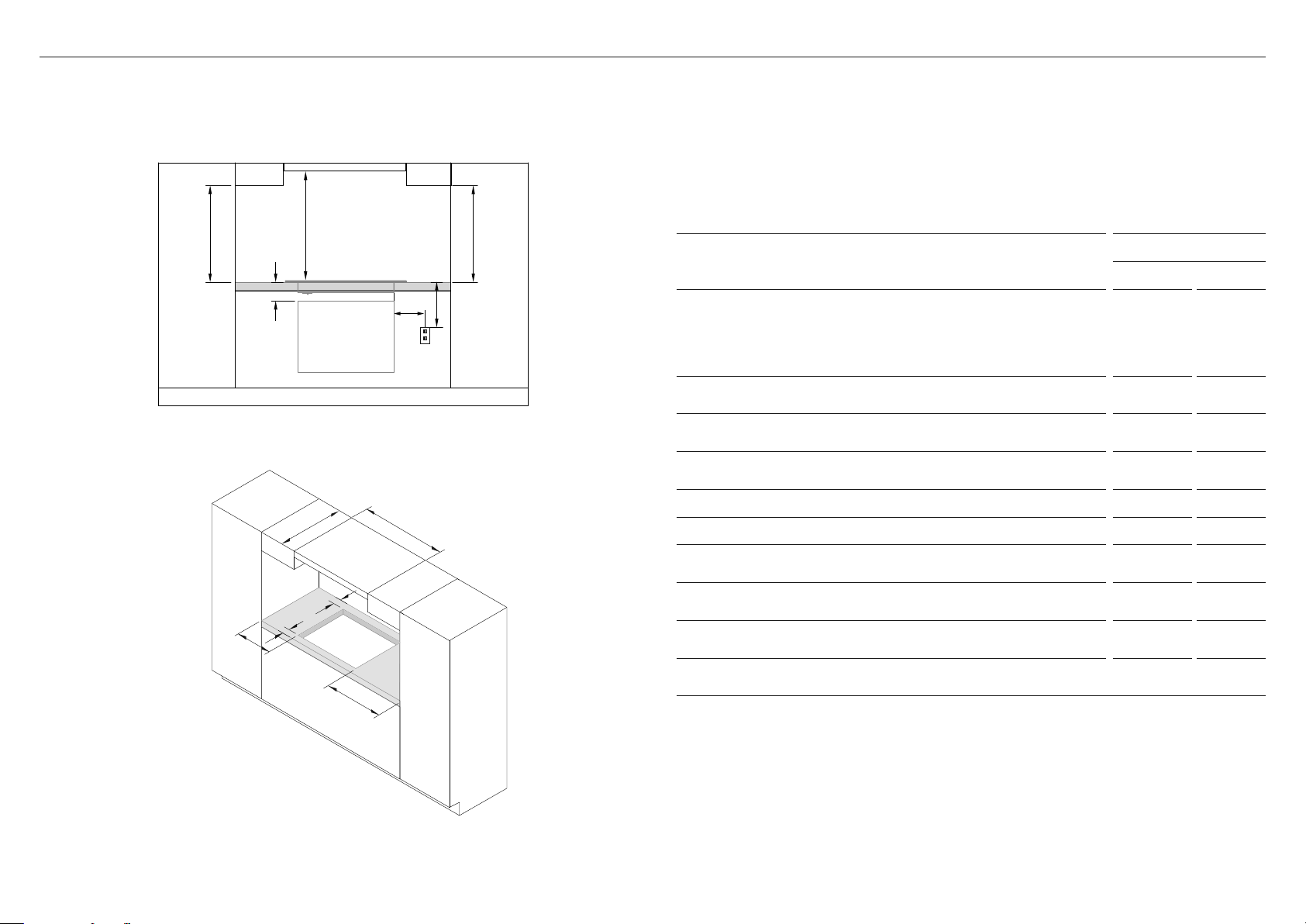
CLEARANCE DIMENSIONS — 30" MODEL
a
b
c
c
d
e
f
g
h
i
jj
Combustible surface
Any materials of a building structure or decorative structure made of wood, compressed
paper, plant fibres, vinyl/plastic or other materials that are capable of transferring heat or
being ignited and burned. Such material shall be considered combustible even though flame-
proofed, fire-retardant treated or surface-painted, or plastered.
CLEARANCE DIMENSIONS
CE304DTB1
INCHES MM
A Minimum clearance from ceramic surface to overhead cabinet
centered above cooktop:
z
Minimum clearance from ceramic surface to rangehood†
z
Unprotected*
+
z
Protected*
+
25 9/16
30
24
650
762
610
B Minimum clearance below top of countertop to top of any
appliance, companion product or obstruction below cooktop
4 1/2 115
C Minimum clearance from side edges of cutout to nearest
combustible surface
2 3/16 55
D Maximum clearance from right edge of cutout to center of
junction box
30 762
E Minimum clearance below top of countertop to junction box 9 1/16 230
F Maximum depth of overhead cabinetry 13 330
G Minimum clearance between overhead cabinets either side of
the cooktop
30 1/8 765
H Minimum clearance from rear edge of cutout to nearest
combustible surface
2 3/16 55
I
Minimum clearance from front edge of cutout to front edge
of counter
1 3/8 35
J Minimum clearance from countertop to overhead cabinet not
directly above the cooktop
17 11/16 450
*To eliminate the risk of burns or fire by reaching over heated surface units, cabinet storage space
located above the surface units should be avoided. If cabinet storage is to be provided, the risk can
be reduced by installing a rangehood that projects horizontally a minimum of 5" (127mm) beyond the
bottom of the cabinets.
+
A=30" (762mm) minimum clearance between the top of the cooking surface and the bottom of an
unprotected wood or metal cabinet; or
A=24" (610mm) minimum when bottom of wood or metal
cabinet is protected by not less than ¼"-thick flame-retardant millboard covered with not less than
No. 28 MSG sheet steel, 0.015"-thick stainless steel, 0.024"-thick aluminum, or 0.020"-thick copper.
†Refer to your range hood installation guide for further details on clearances.
11
ELECTRICAL DIMENSIONS — 30" MODEL
ELECTRICAL DIMENSIONS
CE304DTB1
INCHES MM
A Distance to center of conduit junction from right side of chassis 12 04
B Distance to center of conduit junction from rear of chassis 1 7/ 8 47
C Max height of conduit junction from bottom of chassis 1 1/4 31
FRONT
BOTTOM
a
B
C
12
PRODUCT DIMENSIONS — 36" MODELS
PRODUCT DIMENSIONS
CE365DTB1
INCHES MM
A Overall height of the cooktop 4 1/2 115
B Overall width of cooktop 3 5 7/6 900
C Overall depth of cooktop 20 7/8 530
D Height of cooktop surface 3/16 5
E Height of chassis
(incl. height of conduit junction)
4 5/16 110
F Height of the chassis
(below glass excl. height of conduit junction) 3 1/8 79.5
G Width of chassis 33 3/16 843
H Depth of chassis 19 5/16 490
I Depth of front overhang of cooktop surface 13/16 20
J Depth of rear overhang of cooktop surface 13/16 20
K Depth of side overhang of cooktop surface 1 1/8 29
Actual product dimensions may vary by ± 2 mm.
PRODUCT WEIGHT
CE365DTB1
LB KG
Weight of the product (excluding packaging) 42 19
Refer to ‘Electrical Dimensions’ for details conduit dimension.
FRONT
PLAN
PROFILE
A
kk
d
g
b
c
ji h
e
f
13
FLUSH MOUNTING CUTOUT DIMENSIONS
CE365DTB1
INCHES MM
A Overall width of routered recess 35 5/8 905
B Width of cutout 33 7/16 850
C Depth of cutout 19 1/2 495
D Overall depth of routered recess 21 1/16 535
E Height of routered recess 3/16 5
F Corner radius of routered recess 3/16 5
G Corner radius of cutout max. 3/8 10
CUTOUT DIMENSIONS — 36" MODEL
PLANPLAN
FRONT FRONT
a
b
c
a
b
cd
f
g
CUTOUT DIMENSIONS
CE365DTB1
INCHES MM
A Width of cutout 33 7/16 850
B Depth of cutout 19 1/2 495
C Corner radius of cutout max. 3/8 10
PROUD INSTALLATION FLUSH INSTALLATION
14
CLEARANCE DIMENSIONS — 36" MODEL
a
b
c
c
d
e
f
g
h
i
jj
Combustible surface
Any materials of a building structure or decorative structure made of wood, compressed
paper, plant fibres, vinyl/plastic or other materials that are capable of transferring heat or
being ignited and burned. Such material shall be considered combustible even though flame-
proofed, fire-retardant treated or surface-painted, or plastered.
CLEARANCE DIMENSIONS
CE365DTB1
INCHES MM
A Minimum clearance from ceramic surface to overhead cabinet
centered above cooktop:
z
Minimum clearance from ceramic surface to rangehood†
z
Unprotected*
+
z
Protected*
+
25 9/16
30
24
650
762
610
B Minimum clearance below top of countertop to top of any
appliance, companion product or obstruction below cooktop
4 1/2 115
C Minimum clearance from side edges of cutout to nearest
combustible surface
2 3/16 55
D Maximum clearance from right edge of cutout to center of
junction box
30 762
E Minimum clearance below top of countertop to junction box 9 1/16 230
F Maximum depth of overhead cabinetry 13 330
G Minimum clearance between overhead cabinets either side of
the cooktop
36 915
H Minimum clearance from rear edge of cutout to nearest
combustible surface
2 3/16 55
I
Minimum clearance from front edge of cutout to front edge
of counter
1 3/8 35
J Minimum clearance from countertop to overhead cabinet not
directly above the cooktop
17 11/16 450
*To eliminate the risk of burns or fire by reaching over heated surface units, cabinet storage space
located above the surface units should be avoided. If cabinet storage is to be provided, the risk can
be reduced by installing a rangehood that projects horizontally a minimum of 5" (127mm) beyond the
bottom of the cabinets.
+
A=30" (762mm) minimum clearance between the top of the cooking surface and the bottom of an
unprotected wood or metal cabinet; or
A=24" (610mm) minimum when bottom of wood or metal
cabinet is protected by not less than ¼"-thick flame-retardant millboard covered with not less than
No. 28 MSG sheet steel, 0.015"-thick stainless steel, 0.024"-thick aluminum, or 0.020"-thick copper.
†Refer to your range hood installation guide for further details on clearances.
15
ELECTRICAL DIMENSIONS — 36" MODEL
ELECTRICAL DIMENSIONS
CE365DTB1
INCHES MM
A Distance to center of conduit junction from right side of chassis 9 5/8 245
B Distance to center of conduit junction from rear of chassis 1 7/ 8 47
C Max height of conduit junction from bottom of chassis 1 1/4 31
FRONT
BOTTOM
a
B
C
16
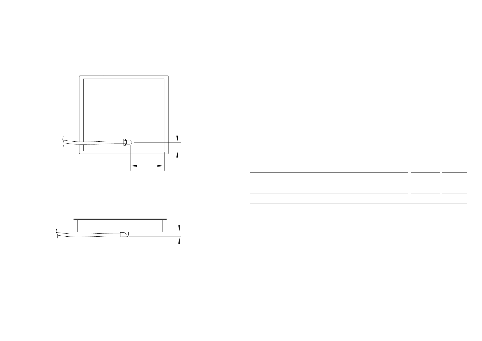
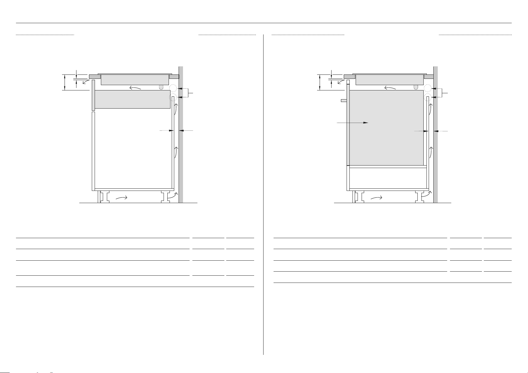
VENTING CLEARANCES
CLEARANCE DIMENSIONS INCHES MM
A Minimum ventiliation gap at the front of the cooktop 3 /16 5
B Minimum clearance from top of benchtop to drawer or other
other obstruction
4 1/2 115
C Minimum ventiliation gap at the rear of the cooktop 2 50
CLEARANCE DIMENSIONS INCHES MM
A Minimum ventiliation gap at the front of the cooktop 3 /16 5
B Minimum clearance from top of the benchtop to top of oven 4 1/2 115
C Minimum ventiliation gap at the rear of the cooktop 2 50
Drawer or other obstruction Oven with cooling fan
Alternatively
2x 2" (50mm) holes in side
wall to allow adequate cool air
Alternatively
2x 2" (50mm) holes in side
wall to allow adequate cool air
Some ovens require
installation in a sealed box.
Please refer to oven install
guide for full specs.
a
b
c
b
a
c
AirflowAirflow
DRAWER OR OTHER OBSTRUCTION OVEN WITH COOLING FAN
17
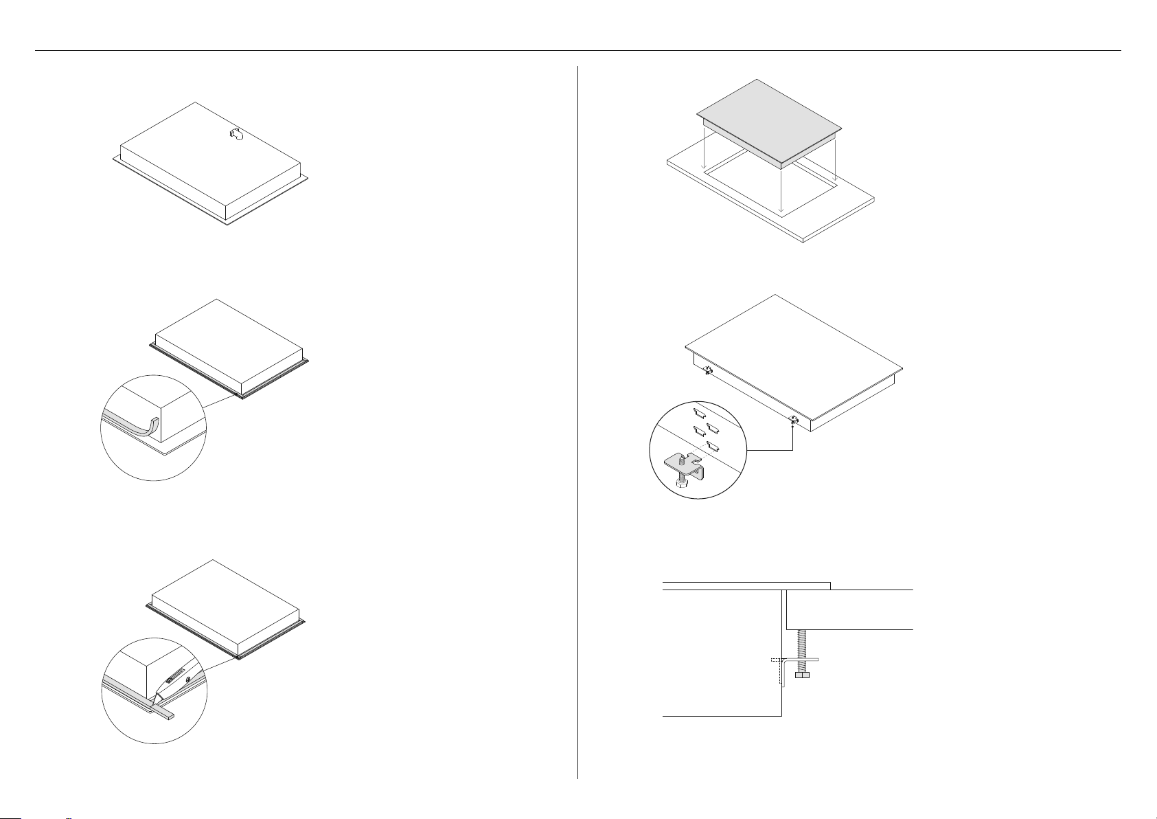
PROUD INSTALLATION
*The number of brackets varies based on your cooktop model
2
1
3
Turn the cooktop upside down
on a protective cover.
Apply adhesive foam seal around
the ceramic overhang, 3/16”
(5mm) in from the edge of the
glass. Ensure the adhesive side is
facing down to form a continuous
seal around the cooktop.
Trim any excess seal using a
sharp knife taking care not to
damage the cooktop or surface.
4
Gently lower the cooktop into
the cutout. Press gently on the
edges of the glass to ensure the
sealing material adheres to the
counter top.
5
Locate the side brackets* to the
appropriate slots on the cooktop
chassis. The correct slot height is
determined by the thickness of
your countertop.
6
Tighten all screws to secure the
cooktop to the countertop.
Ensure cooktop is level.
18
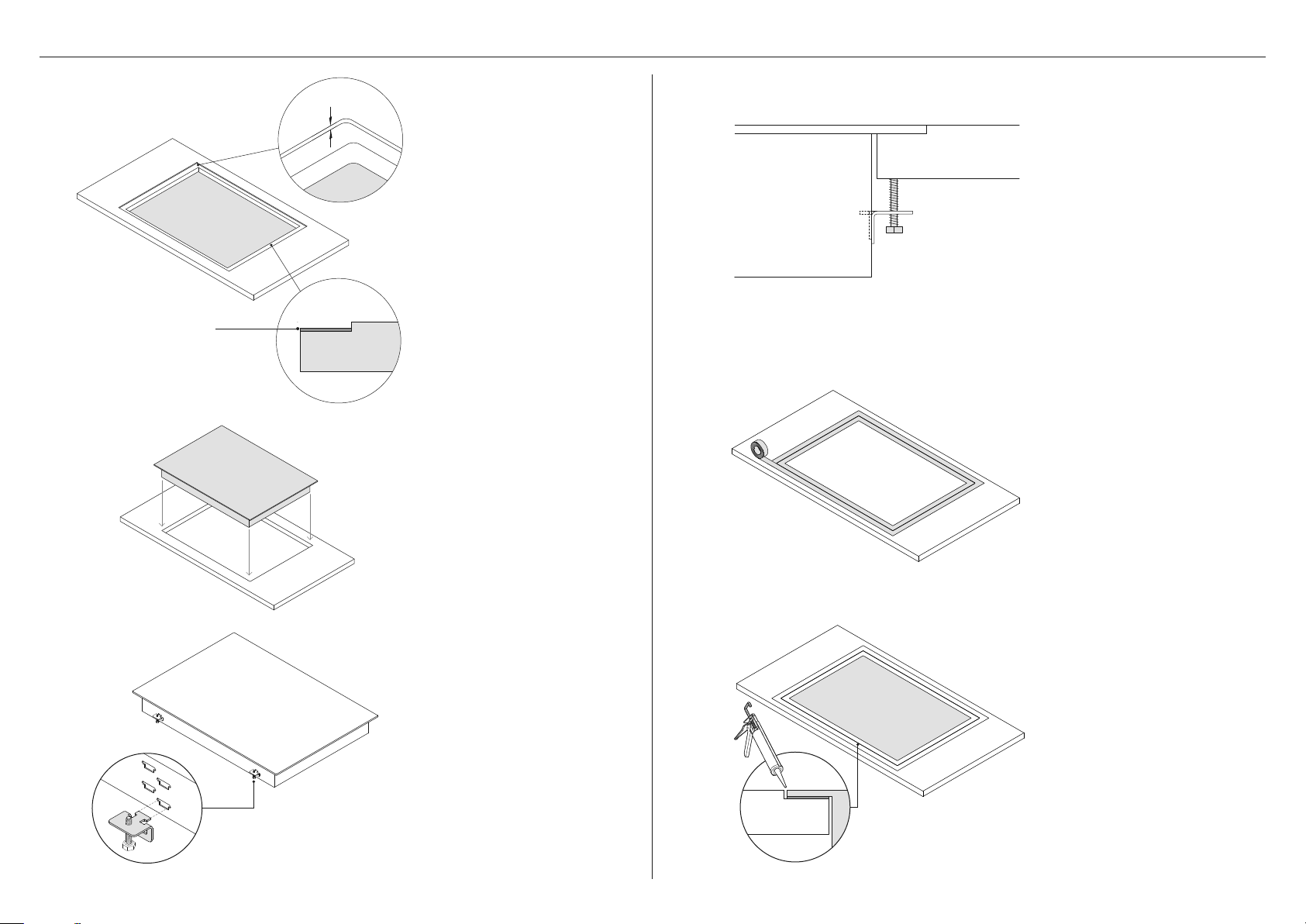
FLUSH INSTALLATION
*The number of brackets varies based on your cooktop model.
2
1
5
Router the countertop to the
specified depth of 3/16” (5mm).
Attach an adhesive tape
along the edges of the
routered recess.
3
4
Adhesive tape
Locate the side brackets* to the
appropriate slots on the cooktop
chassis. The correct slot height is
determined by the thickness of
your countertop.
Gently lower the cooktop into
the cutout ensuring you have
access below the countertop
to fit and secure the brackets.
Tighten all screws to secure the
cooktop to the countertop.
Ensure cooktop is level.
Mask off the area to be siliconed
ensuring both the cooktop and
countertop are protected.
6
Apply silicone in the gap between
countertop and cooktop.
Wipe off any excess silicone.
19
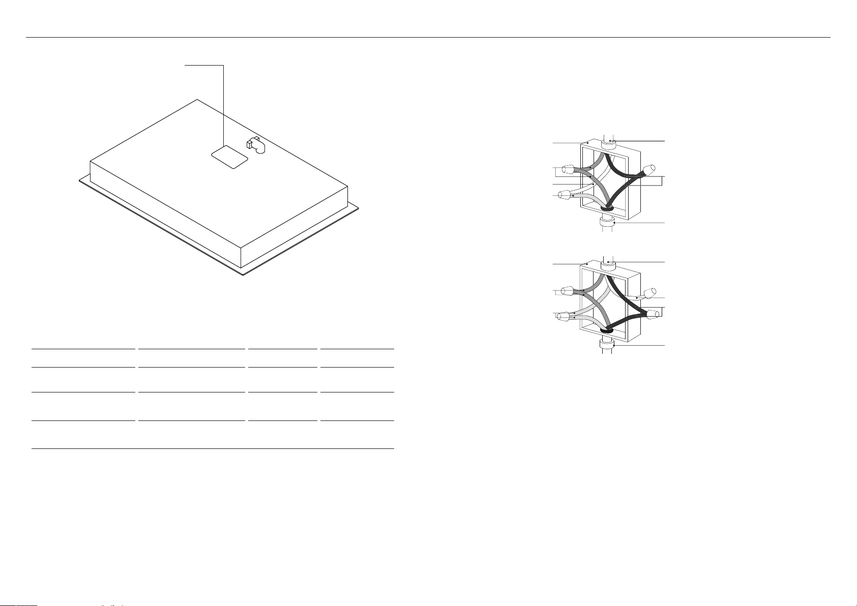
ELECTRICAL CONNECTION
Before connecting the cooktop to the mains power supply check that:
z
The domestic wiring system is suitable for the power drawn by the cooktop.
z
The voltage corresponds to the value given in the rating plate.
z
The power supply cable sections can withstand the load specified on the rating plate.
MODELS MAX. CURRENT DRAW MAX. LOAD VOLTAGE
CE244DTB1
22A
25A
4650W
6200W
208V
240V
CE304DTB1
23A
26A
4800W
6400W
208V
240V
CE365DTB1
34A
39A
7060W
9400W
208V
240V
Rating plate location
Red wires
Green &
Yellow wire
White wire
Black wires
3 wire cable
from power
supply
Black wires
Junction
box
Junction
box
Red wires
Green &
Yellow wires
White wire
4 wire cable
from power
supply
CSA or UL - listed
conduit connector
CSA or UL - listed
conduit connector

20
INSTALLER CHECKLIST
Complete and keep for safe reference:
Model
Serial No.
Purchase Date
Purchaser
Dealer Address
Installer’s Name
Installer’s Signature
Installation Company
Installation Date
Read all installation guidance in this document to see if the unit has been correctly installed.
Ensure that installation has been completed correctly before use.
TO BE COMPLETED BY THE INSTALLER
Ensure that:
Is the cooktop earthed?
Check that there is an adequate and constant flow of cool air from the cabinetry to
the base of the cooktop.
Check that the power supply cable is not accessible via cupboard doors or drawers
and that it is NOT touching the cooktop.
Is the cooktop clamped down securely?
Check that all the cooking zones function correctly. Turn on all of them to a high
setting and leave them on for at least one minute.
Are all elements glowing?
Check that all the cooking zones function correctly. Place suitable pans with water in
them on each zone, then turn all of them on to a high setting. Is the water heating?
Are all touch controls and displays functioning?
To check that the ‘hot surface’ indicators function correctly, turn off all the zones. Is H
displayed in all the cooking zone displays?
Have you demonstrated the basic operation to the customer?
Explain the following to the customer:
1 The importance of taking note of the safety warnings at the beginning of the
installation and user guides, especially for persons with pacemakers or other
electrical implants.
2 The ‘hot surface’ indicators.


592141A 05.20
© Fisher & Paykel Appliances 2020. All rights reserved.
The models shown in this guide may not be available in all markets
and are subject to change at any time.
The product specifications in this guide apply to the specific products and
models described at the date of issue. Under our policy of continuous product
improvement, these specifications may change at any time.
For current details about model and specification availability in your country,
please go to our website or contact your local Fisher&Paykel dealer.
FISHERPAYKEL.COM