
Owner’s manual
U.S. and Canada Version Model Year 2010

2
General considerations
This vehicle, which complies with the NHTSA/EPA certification standards, is equipped with advanced technology and is capable of
achieving high performance levels.
It is equipped with sophisticated active and passive safety systems (described below). Unless otherwise and specifically provided for
by
Ferrari (see the Safety section) it is PROHIBITED to deactivate any safety system.
For proper driving, the following conditions must ALWAYS be met:
- The driver must be in good physical condition, and not under the influence of drugs or alcohol.
- The road regulations must be strictly observed.
- The common rules of caution must always be observed, in relation to the quality/performance of the vehicle, the places where you
are driving and the contingent situations.
Ferrari recommends reasonable and careful use of the vehicle. The driver MUST NEVER allow passengers to increase the risk
connected with driving (e.g., not using the safety systems, such as the seat belts) by failing to observe the mandatory safety rules
that apply to both the driver and the passengers. All occupants must wear their seat belts at all times!
The vehicle MAY NOT be modified or tampered with for any reason whatsoever, as this would affect the standards required for
certification and safety.
The owner of the vehicle is obliged to carefully maintain the vehicle in compliance with the recommended maintenance schedule.
The driver must always pay attention to the warnings signals in the vehicle, in particular to the dashboard warning lights. Even in
cases where the warning lights do not indicate a situation of immediate danger, the driver must always be careful and consider the
possible consequences of the malfunction and the type of information signaled.
Even in the event of routine operations, such as refueling, the driver must take all necessary precautions and check for any spilling
of flammable liquid. These precautions must be taken even if the operation is performed by others. Before starting off, always verify
that the door closing systems are functioning, not only by checking that the relative warning lights are off, but also by trying to
operate them by hand.
The driver must be fully knowledgeable with the vehicle and its controls, so as to handle and drive it as required. Knowledge of the
vehicle can be achieved/improved by attending the driving courses held by Ferrari, which are recommended.

3
Introduction
The names taken from the sports and racing world (e.g., F1, SPORT, RACE) only refer to the technology from which they derive or
to specific vehicle set-ups and they do not authorize the driver to behave improperly while driving.
These above only refers to some general issues that will be specifically dealt with in this Owner’s Manual.
FUELS CONTAINING ALCOHOL
For its fuel injection systems, Ferrari uses components and materials of very high quality. However, no specific tests have been
carried out to assure the reliability of the system when using fuel containing alcohol. Consequently, we recommend that our
customers do not use fuel containing alcohol on Ferrari vehicles.
THE NHTSA’S TOLL-FREE AUTO SAFETY HOTLINE
If you believe that your vehicle has a defect which could cause a crash or could cause injury or death, you should immediately inform
the National Highway Traffic Safety Administration (NHTSA) in addition to notifying Ferrari
S.p.A.
If NHTSA receives similar complaints, it may open an investigation, and if it finds that a safety defect exists in a group of vehicles, it
may order a recall and remedy campaign. However, NHTSA cannot become involved in individual problems between you, your dealer,
or Ferrari S.p.A.
To contact NHTSA, you may call the Vehicle Safety Hotline toll-free at 1-888-327-4236 (TTY: 1-800-424-9153),
(Media inquired: 202-366-9550); go to http://www.safercar.gov;
or write to: Administrator, NHTSA, 1200 New Jersey Avenue, SE., West Building Washington, DC 20590.
You can also obtain other information about motor vehicle safety from http://www.safercar.gov.
THE TRANSPORT CANADA TOLL-FREE AUTO SAFETY HOTLINE
If the affected vehicle is not repaired free of charge to you and within a reasonable time, you may submit a written complaint to Head
of Recalls, Road Safety and Motor Vehicle Regulation, Transport Canada, 2780 Sheffield Road, Ottawa, Ontario KIB 3V9. You may also
telephone Transport Canada at (613) 993-9851.
4
WARNINGWARNING
Because of the high power generated
by the engine, we recommend
that the vehicle only be used by
experienced drivers.
Service
The information contained in this manual
is necessary to get to know your vehicle,
use it properly and keep it in good
condition.
Strictly following the instructions
contained in this manual will help you get
the optimal results and satisfaction from
your vehicle.
We also recommend you have all the
service operations and checks performed
by the Authorized Ferrari Dealers
,
as they have skilled staff and suitable
equipment.
See the “Sales and Service Organization”
manual for the location of the Authorized
Ferrari Dealers.
The
Ferrari Technical Service
Department is at your complete disposal
for any information and suggestions.
Consulting the Manual
This manual refers to vehicles with two
types of gearbox:
• Mechanical gearbox
• F1 electronically-controlled gearbox
Some information may therefore vary
depending on the model.
To facilitate reading the manual, the
topics have been divided into sections
and chapters.
To further facilitate consultation, each
section is identified by a specific color:
General
Provides general information about your
vehicle.
Safety
Describes the main safety systems in the
vehicle.
About your vehicle
Provides all necessary information to use
the vehicle.
Advice for Emergency situations
Provides useful advice for solving
problems that may occur.
Care of the Vehicle
Provides advice for cleaning, care and
routine maintenance of your vehicle.
Table of Notes
This table lists important notes contained
in the Owner’s Manual.
Glossary
Explains the main technical concepts.
Index
Allows you to quickly identify and locate
the information required.
5
Introduction
The important parts requiring particular
attention are easily identifiable in the
various sections.
WARNINGWARNING
Extreme caution required:
Failure to comply with the
instructions could cause hazardous
situations involving personal and
vehicle safety!
Important note:
Warning aimed at preventing any
damage to the vehicle and
consequently hazards involving
personal safety.
Warning for environmental
protection:
Useful advice to help protect the
environment.
Abbreviations/Meanings
Some descriptions and terms with
particular meanings are to be found in
this manual in an abbreviated form:
A.C.
Air Conditioning
ABS
Anti-lock braking system for the wheels
while braking
ASR
Anti-skid regulation during acceleration
F1-Trac
Traction control derived from the
technologies used in the racing sector
ECU
Electronic Control Unit
F1
Electronically-controlled gearbox,
designed with the same technology as
used in the racing sector.
TFT
Thin Film Transistor
For an overview of the abbreviations
contained in this manual, please see the
Glossary.

6
Updating
The high quality level of the vehicle
is subject to constant technological
improvements. Therefore, there may be
differences between this manual and your
vehicle. The Authorized Ferrari Dealers
will be glad to provide you with all the
information about the updates.
All specifications and illustrations
contained in this manual refer to
those resulting as of the printing date.
Specifications may be changed without
prior notice.
Spare parts
We recommend you use genuine Ferrari
parts, which can be obtained from your
Authorized Ferrari Dealer
.
The Ferrari warranty may be voided if
repairs are performed using parts that
are not Genuine Ferrari Parts.
Warranty and Service Book
Each new vehicle comes equipped with a
“Warranty and Service Book”.
This contains the vehicle’s warranty
terms and conditions.
The Warranty and Service Book also
indicates when periodic service is due
according to the “MAINTENANCE
SCHEDULE”.
Vehicle event data
Your vehicle’s driving and safety systems
employ computers that monitor, and share
with each other, information about your
vehicle’s operation. One or more of these
computers may store what they monitor,
either during normal vehicle operation
or in a crash or near-crash event. Stored
information may be read and used by:
- Ferrari North America, Inc.
- Ferrari S.P.A.
- Service and repair facilities
- Law inforcement or government
agencies
- Others who may assert a legal right to
know, or who obtain your consent to
know such information.
“F1-SuperFast” gearbox
The vehicle may come equipped with
an electronically-controlled gearbox
system, controlled by means of the
levers on the steering wheel.
The default setting for the F1 gearbox
is always “AUTO” mode.
Every time the vehicle is started, the
F1 gearbox is in the “AUTO easy
exit” mode, unless the vehicle was in
“AUTO” mode when it was turned off.
To exit the “AUTO easy exit” mode,
operate one of the levers UP and
DOWN
(when the vehicle is
moving) or
press the AUTO button on
the center console.
Even though the system can be used
in “AUTO” mode, it should not be
considered an automatic gearbox.
Therefore, for proper use always follow
the instructions given in this manual.
This new F1 gearbox generation reduces
overall gearshifting times. Using the
elastic power of the transmission devices,
through integrated electronic engine and
gearbox management, the F1-SuperFast
system enhances vehicle performance.
7
Introduction
The different gearshifting stages (torque
reduction and clutch disengagement,
gear disengagement and engagement and
subsequent clutch re-engagement) are
actuated in sequence.
This results in extremely fast gearshifting,
which is reduced to 100 ms (measured as
“acceleration gap”).
Environmental protection
The following chapter contains
useful information for environmental
protection.
Ferrari has designed and constructed a
vehicle using technologies, materials and
devices capable of reducing some of the
harmful impact on the environment.
Using your vehicle respecting the
environment will be your contribution
towards environmental protection.
Fuel consumption as well as engine,
gearbox, brake and tire wear mainly
depend on two factors:
- use of the vehicle
- driving style.
Both factors are influenced by the driver.
Use of the vehicle
- Avoid using the vehicle for short trips.
- Check that the tire pressure is correct.
- Proper periodic maintenance will
contribute to preserving your vehicle in
full working order and to protecting the
environment.
We therefore recommend that you
respect the service due dates indicated
in the “MAINTENANCE SCHEDULE”.
Driving style
- Do not accelerate during the starting
procedure.
- Do not warm up the engine when the
vehicle is stationary.
- Drive prudently and keep a proper
distance suited to the driving speed.
- Avoid sharp and frequent accelerations.
- Turn off the engine if the vehicle is kept
stationary for long periods of time.
- Shift gears using only 2/3 of the speed
permitted for each gear.
WARNINGWARNING
The vehicle is equipped with
emission control and monitoring
systems, which must always function
properly.
WARNINGWARNING
Engine exhaust, some of its
constituents, and certain vehicle
components contain or emit
chemicals known to the State of
California (CA) to cause cancer and
birth defects and reproductive harm.
In addition, certain fluids contained
in vehicles and certain products of
component wear contain or emit
chemicals known to the State of CA
to cause cancer and birth defects or
other reproductive harm.
Battery posts, terminals and related
accessories contain lead and lead
compounds. Wash your hands after
handling.
Used engine oil contains chemicals
that have caused cancer in laboratory
animals. Always protect your skin by
washing thoroughly with soap and
water.

8
This vehicle has been constructed in compliance with the federal environmental and safety standards.
Nevertheless, a few rules should be followed.
Particular attention must be paid to:
- Overheated components: high temperatures develop in the engine compartment in proximity of the exhaust system.
Do not park the vehicle on paper, grass, dry leaves or other flammable materials. They could catch fire if they come into contact
with hot parts of the exhaust system.
Do not fit additional heat shields or remove those fitted on the exhaust system.
Do not let flammable substances come into contact with the exhaust system.
- Moving parts on the vehicle, such as fan belts, etc. are always protected by appropriate systems.
Do not remove the guards or work on the moving parts without taking the due precautions.
- Pressurized systems on the vehicle, such as: the braking system, air conditioning and heating system, cooling system and
lubrication system, which may generate pressure internally.
Do not carry out any work which could cause gas or liquids to escape risking injury to persons and damage.
- Exhaust gas generated by the running engine may be hazardous, especially in closed spaces. As well as consuming oxygen, the
engine discharges carbon dioxide, carbon oxide and other toxic gases.
- The fuel is highly flammable and emits vapors which may be noxious if inhaled.
Do not use open flames or create sparks near the open fuel tank or in any other condition where fuel comes into contact with air.
- The oils used may also be flammable: take the same precautions as necessary for fuel.
- The fluid contained in the battery is poisonous, corrosive and flammable. Do not let it spill or come into contact with the skin,
eyes or objects. Do not use open flames or create sparks near the battery.
Always observe the various warnings contained in this manual.


10
1. General
2. Safety
3. About your Vehicle
4. Advice for Emergency Situations
5. Care of the Vehicle
6. Table of Notes
7. Glossary
8. Index
Vehicle keys
Alarm system
Emergency starting
Electronic alarm
Identification plates and labels
Dimensions and weights
Main engine specifications
Transmission ratios
Performance
Fuel Consumption
Electrical system
Wheels and Tires
Recommended lubricants
and fluids
12
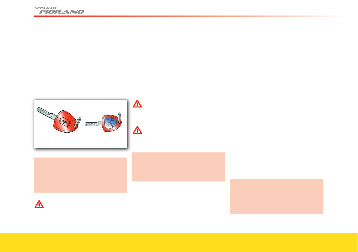
Vehicle keys
The vehicle is delivered with two identical
keys that can be used for:
- starting the vehicle
- locking/unlocking the doors
(central locking)
- activating/deactivating the alarm system
- opening the luggage compartment.
In the event that the keys are lost or
stolen, you can request a duplicate
from your Authorized
Ferrari Dealer
(see section “Duplicating the keys”
on page 14).
WARNINGWARNING
Make sure you record the code
numbers in the space provided in
the “Warranty and Service Book”.
Key codes
A CODE CARD is supplied with the keys.
This card shows the following:
- the electronic code to be used for
“emergency starting”
- the mechanical code for the keys, to be
given to your Authorized Ferrari
Dealer if you request duplicates of the
keys.
WARNINGWARNING
The code numbers on the CODE
CARD must always be kept in a safe
and protected place, not accessible
to others.
WARNINGWARNING
We remind you that the emergency
start procedure can only be
performed using the electronic code
found on the CODE CARD.
In the event of a change of ownership,
it is essential that the new vehicle
owner is provided with all the keys and
with the CODE CARD.
Alarm system
The Ferrari CODE system
The vehicle is equipped with an electronic
immobilizer system (Ferrari CODE
) which
is automatically activated when the
ignition key is removed.
The keys are equipped with an electronic
device which transmits a coded signal to
the Ferrari CODE ECU. Once this ECU
has recognized the signal, the engine can
be started.
This device complies with Part 15 of the
Federal Communications Commission
(FCC) Rules. Operation is subject to
the
following two conditions:
1) the device may not cause harmful
interference
2) the device must accept any
interference received, including
interference that may cause undesired
operation.
Any modifi cation to the equipement
not expressly authorized by the party
responsible for compliance could void
the user’s authority to operate the
equipment.
13
General
8
7
6
1
5
4
3
2
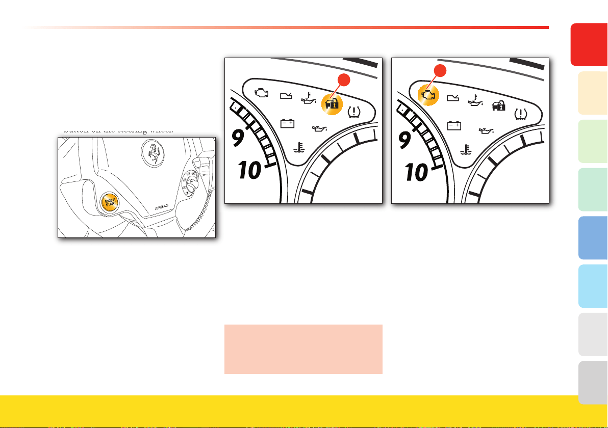
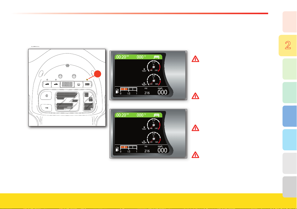
Operation
Each time the ignition key is removed
from the 0 position, the protection system
activates the engine immobilizer.
- When starting the engine, with the key
in postion II press the ENGINE START
button on the steering wheel:
button on the steering wheel:
1) If the code is recognized, the CODE
warning light A on the instrument
panel turns off within one second,
while the OBD warning light B turns
off after about eighteen seconds, once
the ECU has completed its diagnostic
cycle. In these conditions, the
protection system has recognized the
key code and deactivated the
immobilizer.
�
2) If the CODE warning light A remains
on and the OBD warning light B does
not turn off after the ECU has
completed its diagnostic cycle, it
means that the code has not been
recognized. In this case, it is advisable
to turn the key back to position
0 and
then back to II. If the immobilizer
device remains active, try with the
other key provided.
If you are still unable to start the
engine, use the emergency starting
procedure (see page 15) and contact
your Authorized Ferrari Dealer.
�
- While driving, with the ignition key in
position II:
1) If the CODE warning light A
illuminates, it means that the system is
performing a self-diagnostic cycle. At
the fi rst opportunity, you can stop and
test the system: turn off the engine by
moving the ignition key to position
0,
then move the key back to position II
.
The CODE warning light A will
illuminate and should go off within
one second. If the warning light stays
on, repeat the procedure described
previously leaving the key at
0 for
more than 30 seconds.
14
If the problem persists, please contact
your Authorized Ferrari Dealer
.
2) If the CODE warning light A fl ashes,
it means that the vehicle is not
protected by the immobilizer.
WARNINGWARNING
Each key supplied has its own
specifi c code, which must be stored
in the memory of the system ECU.
WARNINGWARNING
Contact your Authorized Ferrari
Dealer immediately to have all the
keys stored in the system memory.
Duplicating the keys
If you request additional keys, provided
that the conditions to satisfy your request
are met, remember that the codes must be
stored (up to a maximum of 8 keys) on all
the keys.
Contact your Authorized Ferrari Dealer
and bring the following with you:
- all the keys in your possession
- the CODE CARD for the Ferrari CODE
system
- a personal identity document
- the documents proving ownership of the
vehicle.
The codes of the keys that are not
available when the new memorization
procedure is performed will be deleted
from the memory, in order to prevent that
any lost or stolen keys are used to start
the vehicle.
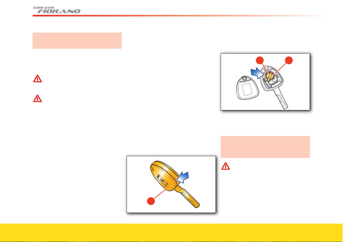
Replacing radio operated control
battery
If you press one of the three buttons and
this does not activate the corresponding
function, before replacing the batteries,
check for correct operation of the alarm
system functions using the other remote
control.
To replace the remote control battery:
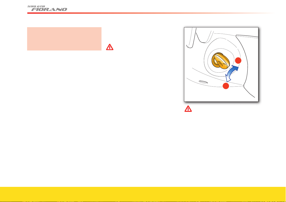
- detach the key cover C, prying it off with
a small screwdriver at the points
indicated by the arrow
�
- extract the battery D, pushing it in the
direction of the arrow to slide it off the
retaining cover
E
- fi t a new battery of the same type,
observing the indicated polarity
- refi t the key cover C.
Do not use sharp tools to replace the
cover and be careful to avoid
damaging it.
WARNINGWARNING
There is risk of explosion if the
battery is replaced with an incorrect
type.
Dispose of used batteries according
to the instructions.

15
General
8
7
6
1
5
4
3
2
Emergency starting
If the Ferrari CODE is unable to
deactivate the immobilizer:
- the CODE
warning light remains
permanently on
- the OBD
warning light goes off after
four seconds and comes back on
immediately afterwards
- the engine does not start.
In this condition, the engine can only be
started with the emergency procedure.
We recommend you read the whole pro-
cedure carefully before performing it.
If you make a mistake during the
emergency procedure, turn the key to
position 0 and repeat the operation from
point 1.
1) Read the 5-digit electronic code found
on the CODE CARD.
2) Turn the key to position II: at this
point, the CODE and OBD warning
lights are on.
3) Fully depress and hold the accelerator
pedal. Approximately 8 seconds later,
the OBD warning light will go off.
Release the accelerator pedal and get
ready to count the number of times
the OBD warning light flashes.
4) As soon as the number of flashes is
equal to the first digit of your CODE
CARD,
depress the accelerator pedal
and hold it until the OBD warning
light goes off (after approximately 4
seconds), then release the accelerator
pedal.
5) The OBD warning light starts flashing
again. As soon as the number of flashes
is equal to the second digit of your
CODE CARD, depress the accelerator
pedal and hold it.
6) Follow the same procedure for the
remaining digits in the code on the
CODE CARD
.
7) When the last digit has been entered,
hold the accelerator pedal down. The
OBD warning light comes on for 4
seconds and then goes off. You can
now release the accelerator pedal.
8) A quick flashing of the OBD warning
light (about 4 seconds) confirms that
the operation has been successful.
9) Start the engine.
If the OBD warning light remains on, turn
the key to
0 and repeat the procedure from
step 1.
This procedure can be repeated an
unlimited number of times.
After an emergency starting procedure, it
is advisable to contact your Authorized
Ferrari Dealer to solve the problem.
Otherwise, you will have to perform the
emergency starting procedure every time
the engine is started.
16
Electronic alarm
The electronic alarm system performs the
following functions:
- remote control for central door locking/
unlocking
- perimeter surveillance, detecting the
opening of doors and lids
- motion surveillance, detecting intrusion
into the passenger compartment
- vehicle movement surveillance.
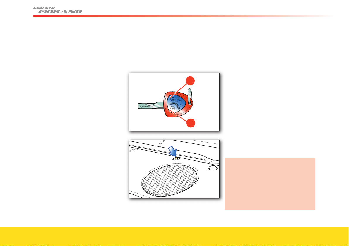
Activation
To turn on the alarm system, press
button F on the key:
- the direction indicators fl ash once
- the system beeps
- the red LED on the dashboard fl ashes
- the central door locking system is
activated and the doors are locked.
The alarm system is activated after
approximately 25 seconds and the alarm
is triggered if:
- a door is opened
- the luggage compartment lid is opened
- the engine compartment lid is opened
- someone attempts to enter the vehicle
from a window
- the power supply is disconnected
- the siren is disconnected
- the vehicle is moved.
When the electronic alarm is activated, the
user may request opening of the luggage
compartment; in this case, the motion and
anti-lift sensors are temporarily
deactivated.
If the luggage compartment is then closed,
the sensors will be reactivated.
If the direction indicators and the red LED
on the dashboard fl ash 9 times when you
activate the alarm system: this means that
one of the doors or the front/rear lid is not
properly closed and therefore is not
protected by the perimeter surveillance.
Check for correct closing of the doors,
rear/front lid and close the open one
without deactivating the alarm system: the
direction indicators fl ashing once indicate
that now the door or the front/rear lid is
closed properly and is protected by the
perimeter surveillance.
If the direction indicators fl ash 9 times
when the alarm system is activated
with doors, rear and front lids properly
closed, it means that the self-diagnostic
feature has detected a malfunction in
the system. Contact your Authorized
Ferrari Dealer to have the system
checked.
17
General
8
7
6
1
5
4
3
2
Deactivation
To deactivate the alarm system, press
button G on the key:
- the direction indicators fl ash twice
- the system beeps twice
- the red LED on the dashboard goes off
- the dome lights and the lights under the
doors turn on
- the central door locking system is
deactivated and the doors are unlocked.
Pressing button
G twice unlocks the doors
and also turns on the low beams for
30 seconds.
The alarm system is off and it is therefore
possible to get into the vehicle and to
start the engine.
If the remote control battery is dead, to
gain access to the vehicle, insert the key
into one of the two door locks, then turn
it to release the lock. The alarm siren will
start to sound.
Start the vehicle following the standard
procedures. The alarm siren will
deactivate.
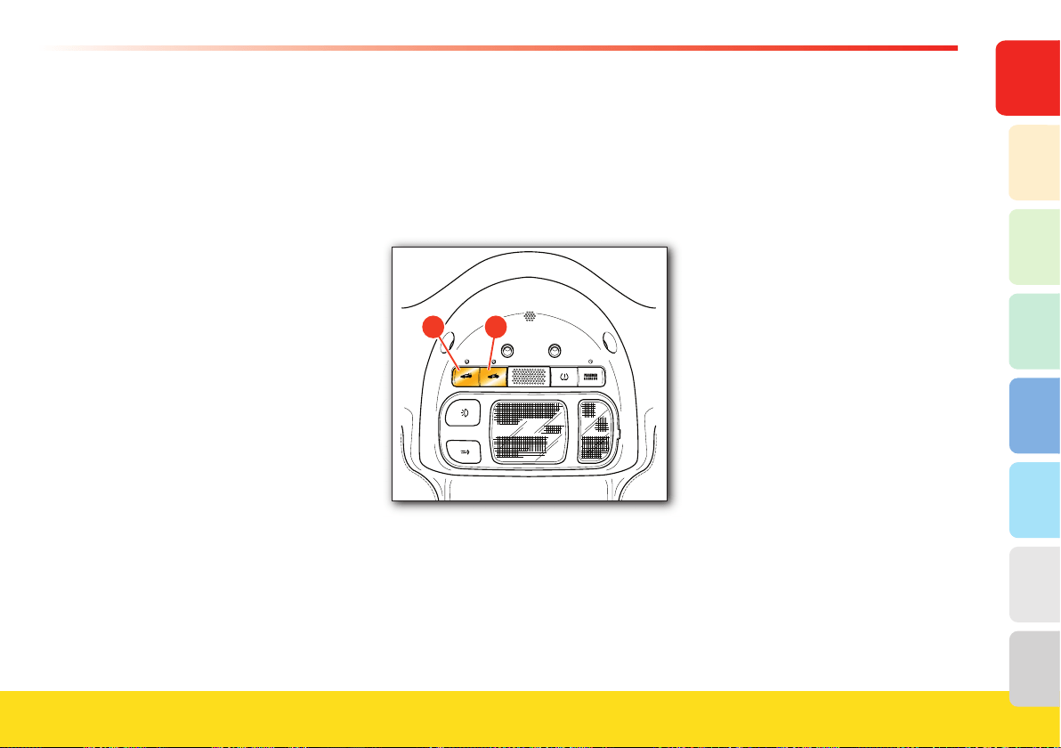
Deactivating the motion sensing system
The motion sensing system can be
deactivated by pressing button
H on the
roof panel. When this function is
deactivated, the LED on the button will
fl ash for about 3 seconds and then will
turn off.
Deactivating the anti-lift alarm
Pressing button I deactivates the anti-lift
alarm. When this function is deactivated,
the LED on the button will fl ash for
about 3 seconds and then will turn off.
Alarm memory
If the CODE warning light appears on the
display when the vehicle is started, this
means that an intrusion has been
attempted.
The alarm system memory is reset by
turning the ignition key.

18
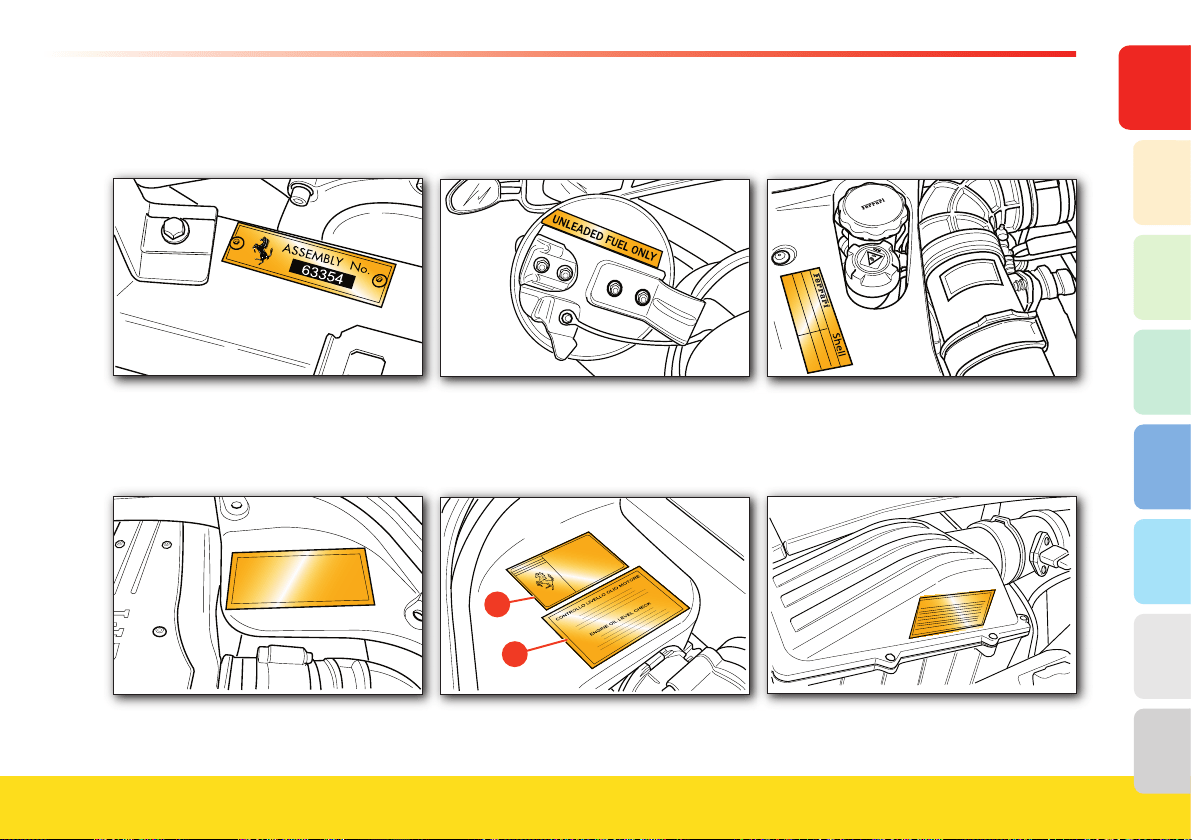
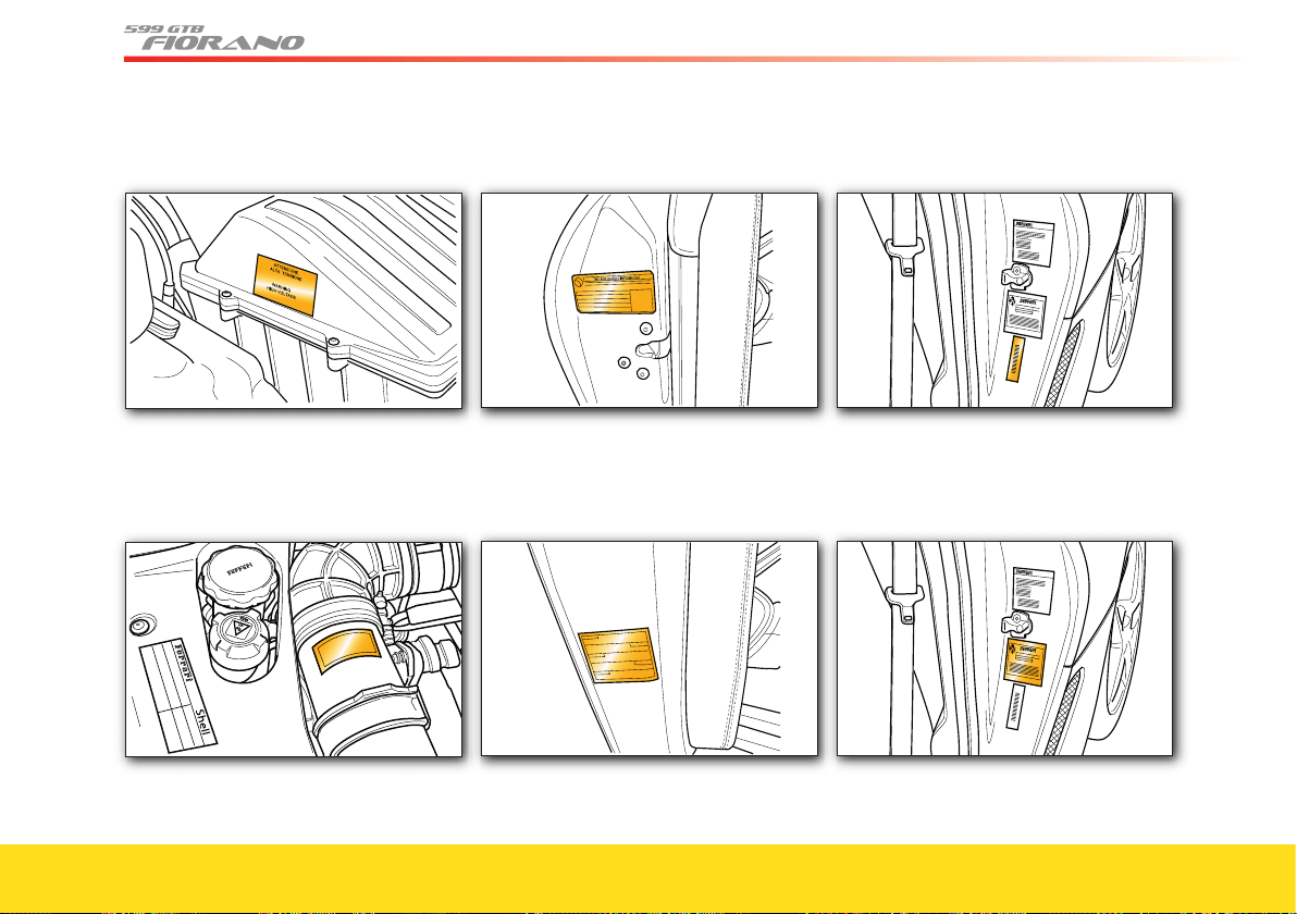
Identifi cation plates and labels
A Assembly number plate
B Emission control data label
C Fuel label
D Paintwork label
E Oil level check label
F Engine oil type label
G Airbag label
H High voltage label
I Anti-freeze label
L Tire pressure label
M Tire pressure and temperature
monitoring system label
N V.I.N. plate
O Safety standard label
P Mercury content warning label
Q Battery master switch instruction label
R Engine type and number
S Chassis type and number
T Gearbox type and number
U Airbag maintenance label
V Child seat warning label
W Airbag label
X Weight sensor label
19
General
8
7
6
1
5
4
3
2
A Assembly number plate
B Emission control data label
C Fuel label
D Paintwork label
E Oil level check label
F Engine oil type label
1.4 bar
A878
G Airbag label
20
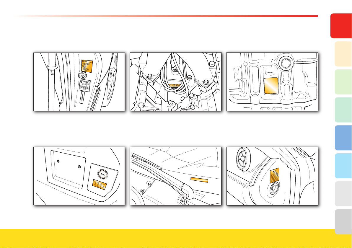
H High voltage label
I Anti-freeze label
1.4 bar
A878
L Tire pressure label
M Tire pressure and temperature
monitoring system label
N V.I.N. plate
O Safety standard label
21
General
8
7
6
1
5
4
3
2
P Mercury content warning label
Q Battery master switch instruction label
R Engine type and number
S Chassis type and number
T Gearbox type and number
U Airbag maintenance label
22
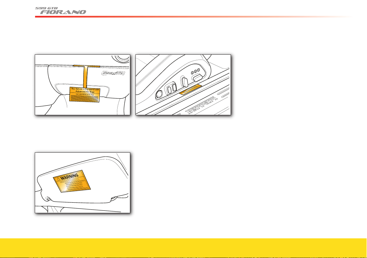
V Child seat warning label
W Airbag label
X Weight sensor label
23
General
8
7
6
1
5
4
3
2
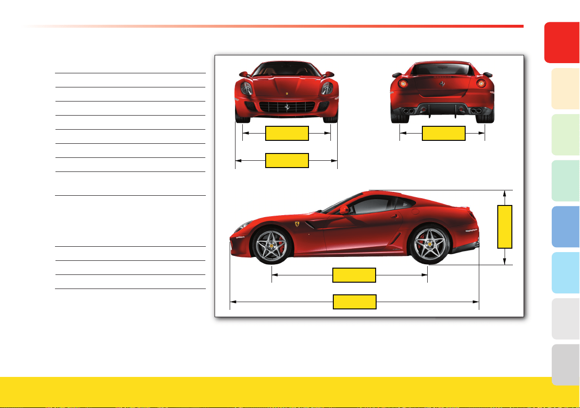
Dimensions and weights
Wheelbase 108.27 in. (2750 mm)
Max. length 183.66 in. (4665 mm)
Max. width 77.24 in. (1962 mm)
Max. height A
52.12 in. (1324 mm)
Front track
B
66.53 in. (1690 mm)
Rear track 63.7 in. (1618 mm)
Curb weight 3,777 lbs. (1715 kg *)
Curb weight
(F1)
3,810 lbs. (1730 kg *)
* with the vehicle fi tted with the most
popular options available.
HGTE package
Max. height A
51.73 in. (1314 mm)
Front track
B
66.81 in. (1697 mm)
B
77.24
108.27
183.66
63.7
A
24
Main engine specifications
Engine Family AFEXV05.7LEV
Type
F140C
Number of cylinders
12
Cylinder bore
3.6 in.
Piston stroke 2.96 in.
Total displacement 5999 cm
3
Compression ratio 11.2:1
Maximum RPM 8250 RPM
RPM limiter 8400 RPM
Max. power
456 kW
(611 HP)
Corresponding RPM 7600 RPM
Max. torque 608 Nm
Corresponding RPM 5600 RPM
Transmission ratios
Gear ratios Differential bevel gear pair ratio
1 41 / 13 = 3.15
2 37 / 17 = 2.18
3 36 / 23 = 1.57 4.18
4 32 / 27 = 1.19 (11 / 46)
5 29 / 31 = 0.94
6 25 / 33 = 0.76
R 41 / 14 = 2.93
Performance
Gearbox type 0 - 100 km/h
0 - 62 mph
0 - 200 km/h
0 - 124 mph
Max. speed
F1 Gearbox Version
3.7 sec 11 sec
> 205 mph (> 330 km/h)
Mechanical Gearbox Version
3.7 sec 11 sec
> 205 mph (> 330 km/h)
25
General
8
7
6
1
5
4
3
2
Fuel Consumption
(miles per US Gallon)
F1 Gearbox Version
City 11
Highway
15
Average fuel consumption
12
Mechanical Gearbox Version
City
11
Highway
15
Average fuel consumption
12
These estimates are based on tests
performed on vehicles equipped with
frequently purchased optional equipment.
The fuel economy values are calculated
pursuant to the new EPA fuel economy
labeling procedure for 2008 and later
model years. You can also obtain
other information from http://www.
fueleconomy.gov.
Reminder: Your actual fuel consumption
may vary depending on your driving style
and habits, vehicle maintenance, optional
equipment installed, road and weather
conditions.
For best fuel economy, shift gears at the
following speeds:
1
st
- 2
nd
10 mph (16 km/h)
2
nd
- 3
rd
15 mph (24 km/h)
3
rd
- 4
th
20 mph (32 km/h)
4
th
- 5
th
25 mph (40 km/h)
5
th
- 6
th
30 mph (48 km/h)
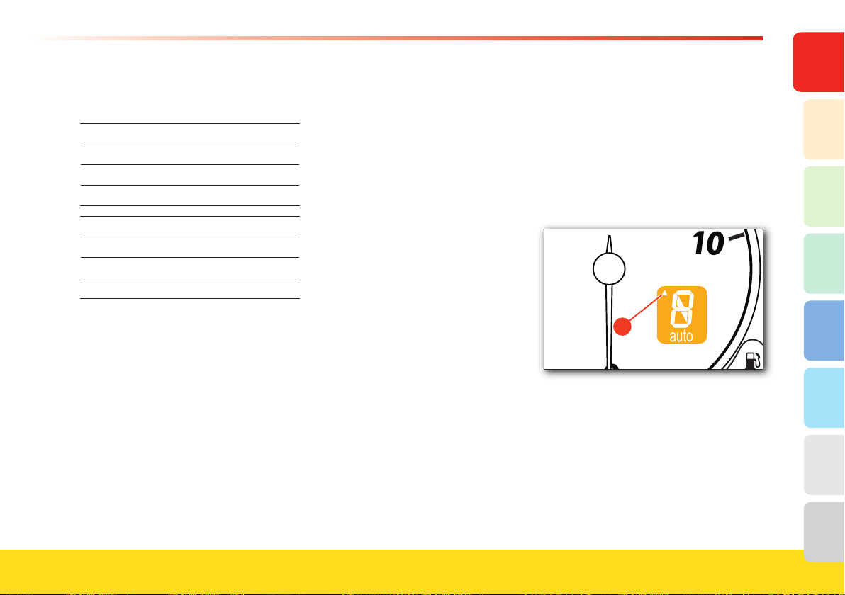
Shift Indicator Light (SIL) operating mode
The graphic symbol
A appears just before
reaching the speed recommended for
operating the UP lever (F1 gearbox
version) or for upshifting using the
gearshift lever (mechanical gearbox).
After shifting gears or after exceeding the
indicated speed, the indicator turns off
even if no gearshift is performed.
�
26
* Tires approved by Ferrari
Inflation pressure (when cold)
Front
Rear Spare tire Front Rear
Pirelli P Zero
245/40 ZR19 305/35 ZR20
32 psi (2.2 bar) 29 psi (2.0 bar)
145/60 ZR20
61 psi (4.2 bar)
* Always check your tires regularly for wear and damage.
Wheels and Tires
Wheel
Front Rear
Spare
8” J x 19” 11” J x 20” 4.5” J x 20”
8” J x 20” optional
11” J x 20” 4.5” J x 20”
Electrical system
Supply voltage
12 v
Alternator
Nippondenso 150 A
Battery
Fiamm 12V, 74 Ah, 440 A
Starter motor
Nippondenso
Wheels and Tires (HGTE package)
Wheel
Front* Rear
8.5” J x 20” 11” J x 20”
*front wheel with reverse rim
Wheel with REVERSE RIM (HGTE package).
The tire must be fitted and removed from the inner part
of the rim only to avoid damaging the rim and pressure
sensor!
This operation must be performed by skilled staff.
Contact your Authorized Ferrari Dealer.
27
General
8
7
6
1
5
4
3
2
Optional tires
Inflation pressure (when cold)
Front
Rear Front Rear
Pirelli P Zero
245/35 ZR20
32 psi (2.2 bar)
Bridgestone RE 050
(Run Flat)
245/35 ZR20 305/35 ZR20
32 psi (2.2 bar) 32 psi (2.2 bar)
Goodyear Eagle
245/40 ZR19 305/35 ZR20
36 psi (2.5 bar) 36 psi (2.5 bar)
Snow tires
Inflation pressure (when cold)
Front
Rear Front Rear
Winter Pirelli
245/40 ZR19 305/35 ZR20
35 psi (2.4 bar) 32 psi (2.2 bar)
Tyres for HGTE package
Inflation pressure (cold)
Front
Rear Front Rear
Pirelli P Zero
245/35 ZR20 305/35 ZR20
32 psi (2.2 bar) 29 psi (2.0 bar)
In order to achieve the best vehicle performance and help ensure safety conditions,
replace all of the snows tires if they are worn.
Please contact your Authorized Ferrari Dealer when you have to fit snow tires.
28
WARNINGWARNING
The traction grade assigned to this tire
is based on straight-ahead braking
traction tests, and does not include
acceleration, cornering, hydroplaning, or
peak traction characteristics.
Temperature
The temperature grades are “A” (the
highest), “B”, and “C”.
Temperature grades represent the tire’s
resistance to the generation of heat and its
ability to dissipate heat under controlled
indoor test wheel conditions. Sustained
high temperature can cause the tire to
deteriorate and can reduce tire life. In
addition, excessive temperature can lead
to sudden tire failure. Grade “C”
corresponds to a level of performance
which all tires installed on passenger
vehicles must meet under the Federal
Motor Safety Standard No. 109. Grades
“B” and “A” represent higher levels of
performance on the laboratory test wheel
than the minimum required by law.
WARNINGWARNING
The temperature grade for this tire is
established for a tire that is properly
inflated and not overloaded. Excessive
speed, under-inflation, or excessive
loading, either separately or in
combination, can cause heat buildup
and possible tire failure.
Treadwear
The treadwear grade is a comparative
rating based on the wear rate of the tire
when tested under controlled conditions
on a prescribed government test course.
For example, a tire graded 150 would
wear one and one-half (1-1/2) times as
well on the government course as a tire
graded 100.
The relative performance of tires depends
upon the actual conditions of their use,
and may differ significantly from the norm
due to variations in driving habits, service
practices and differences in road
characteristics and climate. Check your
tires regularly for wear.
Traction
The traction grades, from highest to
lowest, are “AA”, “A”, “B”, and “C”.
These grades represent the tire’s ability to
stop on wet pavement under controlled
conditions on specified government test
surfaces of asphalt and concrete. Tires
marked “C” have poor traction
performance.
Wheel Replacement
We recommend you read the whole pro-
cedure carefully before performing it.
Wheel bolt
pre-tightening
25.8 - 29.5 ft. lbs.
(35-40 Nm)
Wheel bolt
final tightening
73.8 ft. lbs.
(100 Nm)
Uniform tire quality grading
All passenger car tires must conform to
Federal Safety requirements in addition to
these grades.
DOT quality grades
Tires type
Pirelli P Zero
Tread wear
220 (front)
160 (rear)
Traction
AA
Temperature
A
29
General
8
7
6
1
5
4
3
2
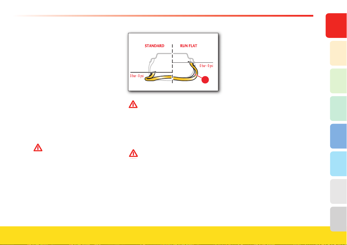
�
WARNINGWARNING
If you are going to use standard tires
on a vehicle that was originally
equipped with “Run Flat” tires, you
must contact your Authorized
Ferrari Dealer to have the
dashboard reprogrammed and to
prevent viewing warning messages
on the TFT display.
Run Flat type tires cannot be fi tted
on the 599 GTB Fiorano with the
HGTE package!
Run Flat tires (optional)
The vehicle can come equipped with
“Run flat” tires. This type of tire has a
reinforced side
B which allows the vehicle
to continue traveling at moderate speed
(50 mph - 80 km/h), even after a puncture,
for a specific distance .
The instrument panel receives the “tire
puncture” information from the tire
pressure monitoring ECU , which monitors
the residual tire life and displays a warning
in the dedicated area of the TFT display
after 30 mi (50 km).
After 60 mi (100 km), a message warning
the driver to stop the vehicle will be
displayed (see “Tire pressure and
temperature monitoring system” on page 55).
WARNINGWARNING
Observing the recommended wheel
alignment values is essential in order
to obtain the best performance and
the longest life of these tires.
More information on these tires and
on the relative pressure monitoring
system can be found in the
“Carrozzeria Scaglietti” Owner’s
Manual.
30
Recommended lubricants and fluids
Parts to be refilled Quantity Fill with Ref. Page
Engine Total system capacity 12.68 qts. (12 l) HORSE POWER
SAE 10W-60
161
Oil level between Min. and Max.
1.58 qts. (1.5 l)
Oil consumption
(depending on driving conditions)
1.06-2.11 qts./600 miles
(1.0 ÷ 2.0 l/1,000 km)
Gearbox and differential
5.28 qts. (5 l) TRANSAXLE SAE 75W-90 161
F1 gearbox system 1.06 qts. (1 l) DONAX TX
161
Braking and clutch system
F1 braking system
1.58 qts. (1.5 l)
DONAX UB BRAKE FLUID
DOT4
Ultra
163
Cooling circuit 6.34 US Gallon
(24 l)
GLYCOSHELL at 50% 161
Hydraulic steering system 1.06 qts. (1 l) DONAX TX 163
Steering box
0.22 lbs. (100 g)
Fuel tank
27.74 US Gallon (105l)
Premium Gasoline (91-94 A.K.I.) 71
Reserve 5.28 US Gallon (20 l) Unleaded fuel
Air conditioning and heating system -
Compressor 10.07 cu.in.(165 cc) DELPHI RL 488 “R 134 A”
Refrigerant 1.65 ± 0.11 lbs. (750 ± 50 g)
Windshield washer fluid tank 6.86 qts. (6.5 l) Windshield washer fluid 164


1. General
2. Safety
3. About your Vehicle
4. Advice for Emergency Situations
5. Care of the Vehicle
6. Table of Notes
7. Glossary
8. Index
Seat belts
Pretensioners
Child safety
Airbag
Side Airbag
Advanced Airbag System
ABS
CST
F1-Trac
Tire pressure and temperature
monitoring system
34
Seat belts
If used correctly, the seat belts, in
combination with the pretensioners, have
been designed to help protect the wearer
from a variety of impacts while fi rmly
securing the occupants within the
structure of the vehicle.
WARNINGWARNING
Ferrari urges you to use the seat
belts correctly fastened and adjusted
at all times!
WARNINGWARNING
Correct use of the seat belts can help
reduce the risk of serious injury in
the event of an accident.
WARNINGWARNING
All passengers must wear their seat
belts!
The seat belts are lap and shoulder seat
belts with automatic retractor and an
emergency inertia locking system on the
retractor unit, which is fi tted with a
pretensioner.
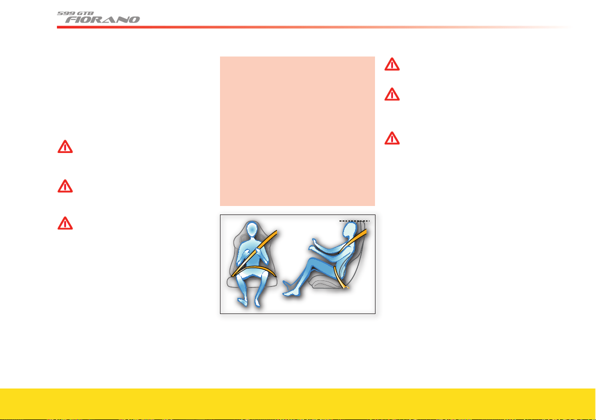
To help ensure optimal protection, keep
the seat backrest in the upright position,
make sure that your back is properly
resting on it and adjust the seat belt
correctly, fitting it closely across your
chest and pelvis.
The lap portion of the seat belt must be
fitted low across your pelvis, resting on
the pelvic bones. Take care that the lap
portion of the lap belt does not rest on
the abdomen, as this can result in an
increased risk of injuries. Adjust the seat
height to help keep the lap portion of the
belt low on the pelvis.
WARNINGWARNING
Do not pass the seat belts over sharp
edges. They could tear.
WARNINGWARNING
Do not attach or pin anything onto
the seat belts. This could reduce
their initial strength and cause them
to tear in the event of a crash.
WARNINGWARNING
Do not bring cutting edges in
contact with a seat belt. They may
get damaged and consequently
break in the event of a collision.
If a seat belt has been brought in
contact with a cutting edge, or has
been used to pin something on it,
have it immediately replaced at your
Authorized Ferrari Dealer.
35
8
7
6
5
4
3
2
1
Safety
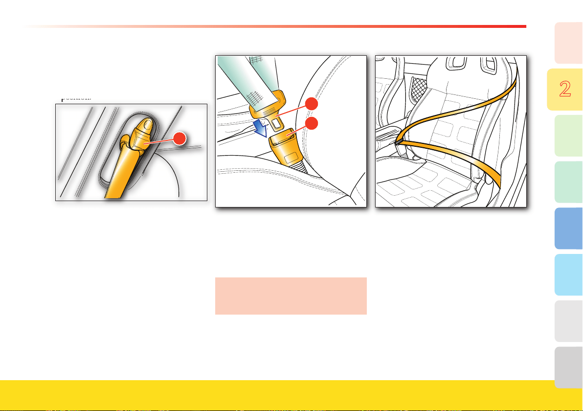
Adjusting the seat belt height
- Press button A to release the adjustment
device and move it to the desired
position.
position.
�
- Always check that it is locked. The seat
belt is properly adjusted when it passes
about mid-way between the end of the
shoulder and the neck. The lower part
must fi t tightly across the pelvis and not
the abdomen.
Fastening the seat belts
Adjust the seat and seat backrest properly.
- Grip the buckle
B, slowly pull the belt
and insert the tang into its receptacle
C.
Should the belt lock while pulling it, let
it rewind slightly and then pull it again
without sharp movements.
- Make sure that it has clicked into place.
- Position the seat belt correctly: the lap
portion of the seat belt must rest low on
the pelvis, and lean onto the pelvic
bones.
Do not use any objects (e.g., spring
clips, locks, etc.) that hold the seat belt
away from your body.
- Pay attention that the lap portion of the
seat belt does not move up into the
abdomen.
- Avoid “slouching” positions, as this can
cause the lap portion of the seat belt to
move up to the abdominal region.
- The upper portion of the seat belt must
be adjusted so that it passes over the
shoulder, mid-way between the end of
the shoulder and the neck.
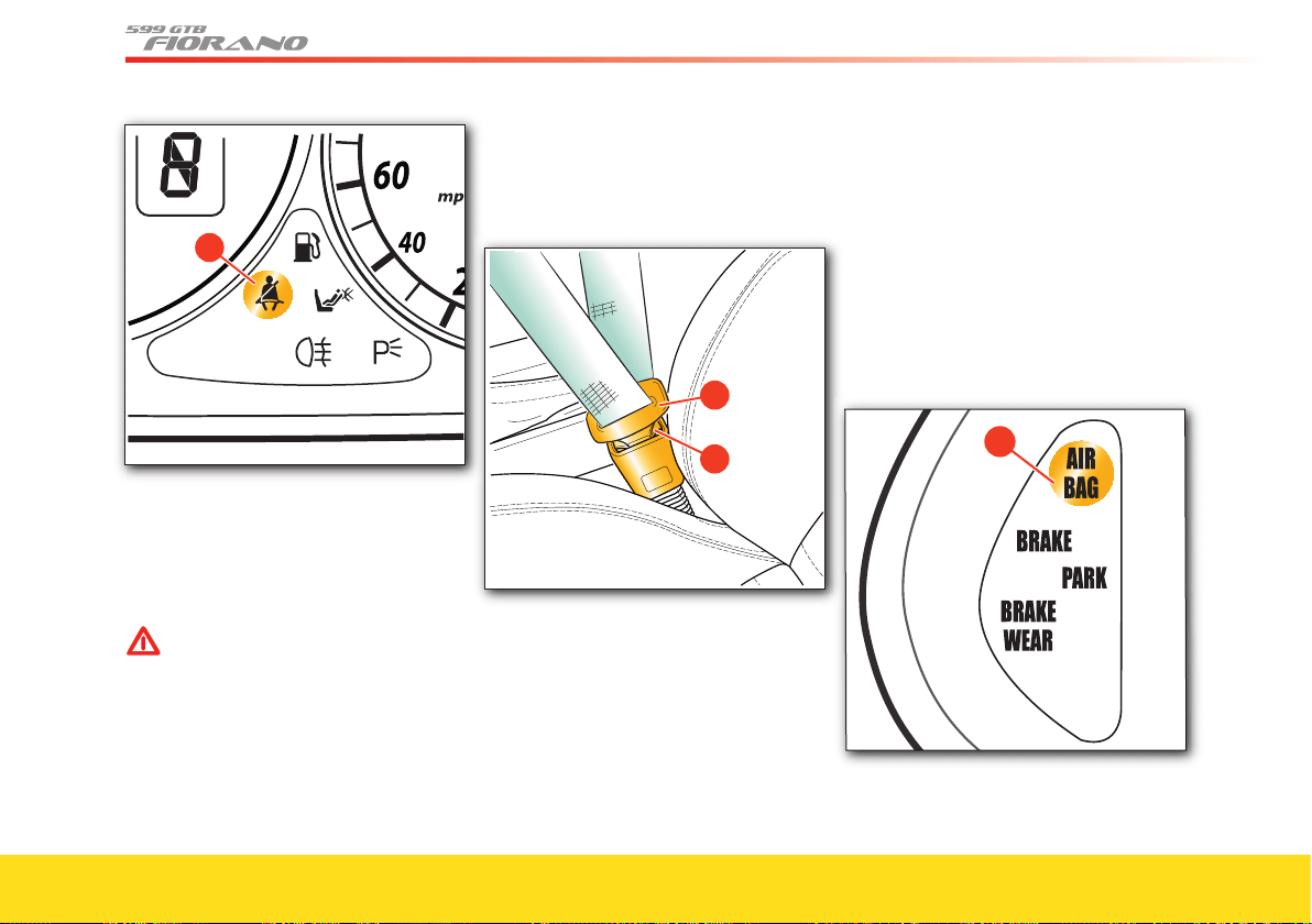
If the driver’s seat belt is not fastened,
when you turn the ignition key to
position II, the warning light D
illuminates.
36
�
If the passenger’s seat belt is not fastened
and the system detects the presence of an
adult in the passenger’s seat (according to
the Occupant Classifi cation System), a
warning will appear on the TFT display.
WARNINGWARNING
Do not allow children to be held on
a passenger’s lap using only one seat
belt for both of them.
In the event of a crash, the weight of
the adult would crush the child
against the seat belt.
This can result in serious injuries or
death for the child.
Unfastening the seat belts
- Push the release button E.
- Guide the seat belt buckle
B back to its
rest position.
Emergency tensioning device, seat
belt load limiter
The seat belts in this vehicle are equipped
with emergency tensioning devices (also
called “pretensioners”) and load limiters.
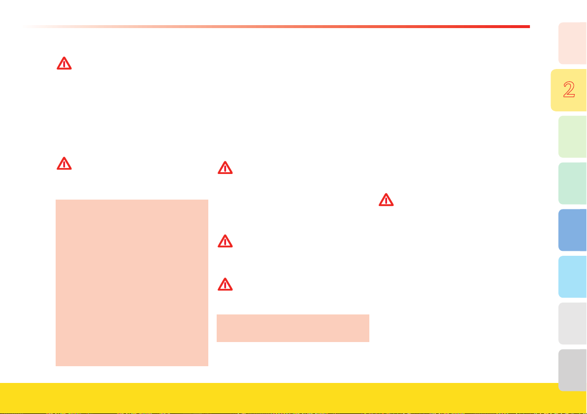
Pretensioners
The pretensioners are designed to activate
in the event of certain head-on collisions
of suffi cient force, or in a side collision of
suffi cient force. The seat belt will rewind
a small amount just before the restraining
action begins, thereby helping to ensure a
proper hold around the occupant’s body.
Activation of a pretensioner is signaled by
the illumination of the warning light A on
the instrument panel.
�
37
8
7
6
5
4
3
2
1
Safety
WARNINGWARNING
After activation, the pretensioner no
longer functions and cannot be
repaired, under any circumstances.
Contact your Authorized Ferrari
Dealer for replacement.
When a pretensioner is activated, a small
amount of smoke is released. This smoke
is not harmful and does not indicate the
presence of a fire.
WARNINGWARNING
All work on any part of the safety
system components must be
performed only by an Authorized
Ferrari Dealer.
It is not permitted to remove or make
modifications of any kind to the seat
belts, belt retractors and pretensioners.
Maintenance work involving strong
impacts, vibrations or heating of the
pretensioner area may activate them;
vibrations caused by road bumps will
not have this effect.
Activation of the pretensioners only
depends on the status of the seat belts
and is not affected by the occupants’
presence.
If the seat belt is not fastened, the
pretensioner will not activate, even if
the seat is occupied.
The seat belt is equipped with a load-
limiting device, which is designed to
reduce the restraining force exerted by
the seat belts on the occupant’s body
during a collision. This device controls the
force level with which the seat belt is
released during a collision.
Child safety
WARNINGWARNING
Never drive with a child in a
rearward-facing child seat in the
front seat if the "PASSENGER
AIRBAG OFF" warning light is not
illuminated. Airbag deployment can
cause serious injuries or death to a
child in a rearward-facing child seat.
WARNINGWARNING
Established legislation in some
countries already provides that
children under 12 years of age may
not travel in the front passenger seat.
WARNINGWARNING
Child seats may only be installed
with the seat fully lowered and
pushed backward.
Do not tamper with the seat belts or
child restraint systems.
Because of their size and shape, children
are at greater risk for injuries than adults.
Suitable restraint or safety systems must
be used.
All person whose physical characteristics
(e.g., height, weight) meet the limit values
provided by established legislation in each
country must be protected by
approved restraint or safety systems (i.e.,
certified child seats, cradles, and cushions).
In any case, you are advised to always use
certified child restraint systems bearing
the proper test marking.
WARNINGWARNING
Incorrect fastening of a child
restraint system increases the risk of
injury to the child in the event of a
collision.
- The seat belts in the vehicle have been
designed and tested to protect persons
weighing at least 79 lbs (36 Kg) and
taller than 59 in. (1.50 m).
- To properly protect any passengers
outside these limits, specific restraining
systems with dedicated belts or
accessories capable of adapting the
child’s position to the vehicle’s seat belts
must be fitted.
38
For installation and use of a child restraint
system, always follow the instructions that
the manufacturer of the devices is
required to supply.
Always follow the instructions supplied
with the child restraint system precisely.
Keep the instructions in the vehicle
together with the documents and this
manual. Never use second-hand child
seats which are not provided with
instructions for use.
In case of an accident, replace the child seat.
The passenger-side seat belt in this vehicle
is equipped with special retractors to help
properly fasten a child restraint. To install a
child restraint, pull the seat belt out
completely. The retractor will now only
allow the seat belt rewinding and will not
allow the seat belt to be pulled out.
Follow the instructions on the child
restraining system for proper installation in
the vehicle.
Check that the seat belt locking
mechanism has been activated by trying to
pull out a small amount of seat belt with
moderate force. If the system has been
activated, this should not be possible.
To deactivate this feature, release the seat
belt buckle and allow the seat belt to
retract completely.
WARNINGWARNING
Always deactivate this feature prior
to using the seat belt for normal use.
Having the retractor locked can be
dangerous when the seat belt is used
for directly restraining a passenger.
If you must, in an emergency situation,
carry a child in a rearward-facing child
seat in the front passenger seat:
- adjust the seat to the most rearward
position (avoiding contact with the
interior)
- adjust the headrest to the lowest
possible position
- install the child seat when the key is in
the 0 position, following the instructions
provided with the child seat
WARNINGWARNING
Installing a child seat with the key in
position II can result in induced
injuries.
- the extra weight applied on the seat
during child seat installation might delay
correct occupant classifi cation if the child
seat is mounted with the key in position II
- always check that no objects are stuck
underneath the seat
- always check that no objects are loose on
the fl oor, either in front, or behind the
seat
- check that no objects contact the seat
39
8
7
6
5
4
3
2
1
Safety
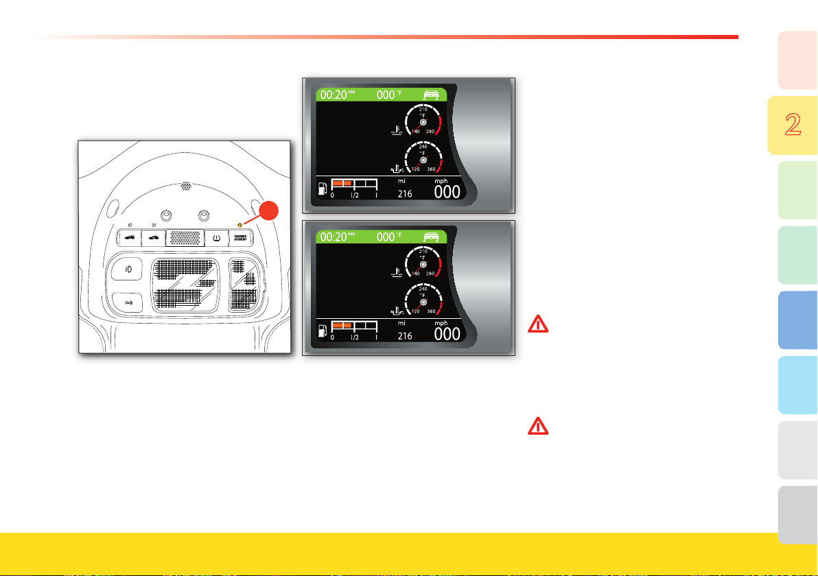
- make sure that the “PASSENGER
AIRBAG OFF” warning light
A on the
roof panel is illuminated and does not
fl ash
fl ash
�
- drive carefully and slowly avoiding any
hard braking and acceleration
- do not distract yourself from driving by
checking on the child. If you need to
check on the child's condition, stop the
vehicle in a safe place
- when it is not dangerous (e.g., stops at
“red” traffi c lights) periodically check on
the “PASSENGER AIRBAG OFF”
warning light status. If the “PASSENGER
AIRBAG OFF” warning light goes off, a
warning will also be temporarily viewed in
the multifunction display in the instrument
panel, but you may be busy with driving
and not notice it
- if the “PASSENGER AIRBAG OFF”
warning light goes off, carefully stop the
vehicle in a safe place. Check that no
objects are stuck underneath or behind
the passenger seat.
If the “PASSENGER AIRBAG OFF”
warning light is still not illuminated,
move the key to the
0 position and wait
a few seconds. If , at restart, the lamp is
still not illuminated, call for assistance
WARNINGWARNING
Never drive with a child in a
rearward-facing child seat in the
front seat if the "PASSENGER
AIRBAG OFF" warning light is not
illuminated. Airbag deployment can
cause serious injuries or death to a
child in a rearward-facing child seat.
WARNINGWARNING
Never carry a child in a adult’s lap. In
the event of a crash, the weight of the
adult could crush the child against
the seat belt (or the dashboard). This
could result in serious injuries or
death for the child.
WARNINGWARNING
This is a high-performance vehicle.
You are strongly urged not to carry
children in this vehicle, since they
can also be injured by hard
accelerations.
WARNINGWARNING
Always drive slowly and carefully
when carrying a child. Hard
accelerations due to sport-style
driving can be dangerous for
children, even if no crash occurs.
40
WARNINGWARNING
Children must always be seated in
a child restraint system specifically
designed for their size, and must be
properly restrained.
WARNINGWARNING
Unrestrained occupants, including
children, can be propelled against
the dashboard or the windshield by
hard braking and by crash forces.
This can result in serious injuries or
death.
WARNINGWARNING
Do not tamper with seat belts or
child restraint systems.
Established legislation in some
countries already provides that
children under 12 years of age may not
travel in the front passenger seat.
WARNINGWARNING
The ignition key must always be
turned to position 0 when installing a
child seat on the front passenger seat.
Transport of persons with disability
If it is necessary to modify the advanced
airbag system of your vehicle to
accomodate a person with disabilities,
contact your
Authorized Ferrari Dealer.
WARNINGWARNING
The advanced airbag system of your
vehicle is not designed to protect
adults with disability that require
deactivation of the passenger’s or
driver’s airbag.
WARNINGWARNING
If you or another occupant is an
adult with a medical condition that
requires airbag deactivation, please
contact your Authorized Ferrari
Dealer.
WARNINGWARNING
As long as the airbag is activated,
persons with disability are advised
not to travel in the vehicle in order
to avoid the risk of serious injuries
or death, even in minor crashes.
41
8
7
6
5
4
3
2
1
Safety
Airbag
WARNINGWARNING
The airbag is not a substitute for the
seat belts. Correct use of the seat
belts, in combination with the
airbag, will offer protection for the
driver and passenger in the front
seats in the event of a head-on
collision.
WARNINGWARNING
Front airbags cannot offer protection
in side crashes, certain front-angular
crashes, roll over events or in
secondary impacts (if a second crash
happens after the airbags have been
deployed in a previous crash). The
seat belts are designed to help
reduce the risk of injuries in roll
over events and secondary front
impacts.
A properly fastened seat belt is
needed to help protect occupants in
roll over events and secondary front
impacts.
WARNINGWARNING
Front airbags are designed to not be
deployed in low severity frontal
crashes. The seat belts can help
reduce injuries in low severity
crashes. A properly fastened seat belt
is needed to help protect the
occupants in low severity frontal
crashes.
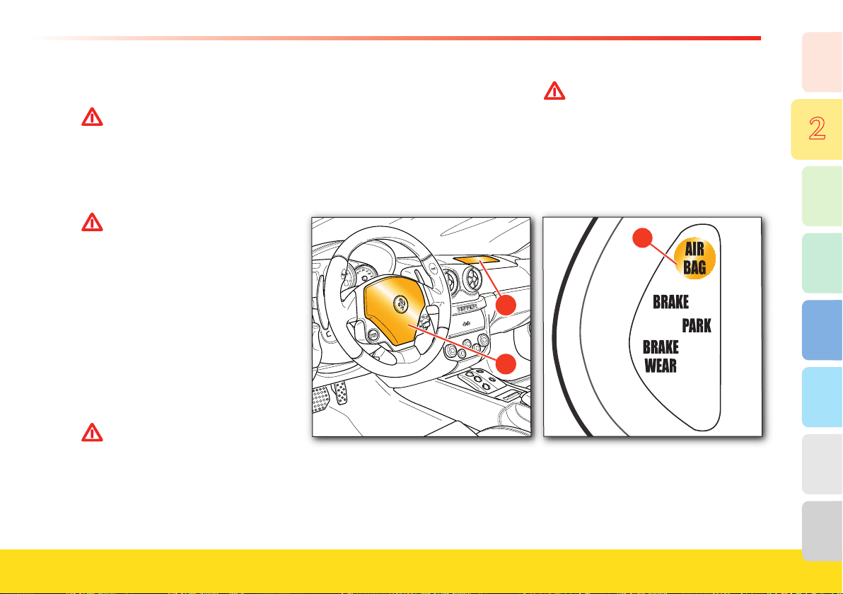
Airbag system components
The airbag system is composed of two
cushions that are designed to infl ate
almost instantaneosly. One A, is on the
driver side, in the center of the steering
wheel, and the other B on the passenger
side, inside the dashboard.
B
A
WARNINGWARNING
When the ignition key is turned to
position II, the warning light C
illuminates. If no malfunctioning is
detected, it will go off after 4
seconds. If the warning light does
not illuminate, if it remains on or if it
illuminates while driving, contact
your Authorized Ferrari Dealer
immediately.
�
42
Operation
The airbags are controlled by an ECU
that is designed to activate them in the
event of certain head-on collisions of
sufficient force.
In the case of a collision with an impact
force that causes deceleration exceeding
the value set for the internal sensor, the
ECU will transmit a signal to deploy the
airbags. The airbags will begin to inflate,
breaking the cover along the breakage line
and will deploy completely in a few
hundredths of a second. Once deployed,
they will serve as protection between the
driver and/or passenger and the structures
that could cause injury.
The airbags deflate immediately
afterwards.
The passenger airbag deployment is
further influenced by the occupant’s
weight, as determined by the Occupant
Classification System (see also page 50 for
more details about the Occupant
Classification System).
If the front passenger is classified as being
a child by the Occupant Classification
System, the passenger airbag will never
deploy, no matter how high the crash
severity.
It is possible that the driver’s airbag is
deployed in a crash, and the passenger’s
airbag is not deployed. This could
happen if the front passenger is
classified as a child by the Occupant
Classification System (see also page 50
for more details about the Occupant
Classification System).
WARNINGWARNING
The driver and passenger are both
advised not to travel handling objects
(e.g., beverage cans or bottles, pipes,
etc.) that could cause injury in the
case of airbag deployment.
When the system is activated, gases are
released in the form of fumes, together
with the gas used for inflating the
airbags.
These gases are not harmful. The
presence of smoke is not indicative of a
fire.
WARNINGWARNING
Always drive with your hands on the
rim of the steering wheel so that, in
case of activation, the airbag can
deploy without obstruction.
Driving with your hands inside the
steering wheel rim or on the airbag
cover increases the risk of injury for
your wrists and arms.
WARNINGWARNING
The driver and passenger must
always fasten their seat belts and sit
in an upright position, as far as
possible away from the airbag, in
order to help ensure protection in all
types of collision.
WARNINGWARNING
Always keep the backrest of your seat
in the upright position and sit with
your back properly resting against it.
Do not modify the system components
or wiring, under any circumstances.
WARNINGWARNING
With the ignition key inserted and in
position II, although the engine is off,
the airbags can still be activated when
the vehicle is stationary if it is hit by a
moving vehicle.
Thus, even with the vehicle
stationary, do not put children in the
front seat. In addition, remember that
if the ignition key is in position 0,
none of the safety devices (airbags or
pretensioners) will be activated in the
event of a collision. Failure of the
airbags to inflate in these
circumstances is not indicative of a
system malfunction.
WARNINGWARNING
Therefore, even with the vehicle
stationary, do not allow children to
sit on the front seat.
43
8
7
6
5
4
3
2
1
Safety
Do not cut or tamper with the
connectors of the airbag harness or on
the airbag modules.
WARNINGWARNING
Never place an object over or near
the airbag covers.
In the event that the airbags are
deployed, these objects would be
projected into the passenger
compartment at very high speed. The
object will be transformed into a
projectile propelled in the passenger
compartment. This could cause
serious injuries.
WARNINGWARNING
Never modify the airbag modules. Do
not damage the airbag modules (for
example pinning something onto
them or pressing objects against their
covers).
If, for any reason, an airbag cover gets
damaged, have the airbag module
immediately checked by your
Authorized Ferrari Dealer.
Activation of a damaged module
could cause serious or fatal injuries.
Never remove the steering wheel. If
necessary, this procedure should only
be performed by an Authorized Ferrari
Dealer.
All the airbag system components must
be replaced after an accident that
caused airbag deployment.
Following an accident not involving
airbag deployment, contact your
Authorized Ferrari Dealer to have the
system checked and any system
components that may be damaged or
malfunctioning replaced.
WARNINGWARNING
Damaged or defective components of
the airbag system cannot be repaired
and must be replaced.
Improper operations performed on
the system components may cause
failures or accidental deployment of
the airbags with consequent damage
and injury, even fatal.
The airbag system components have
been specially designed only for this
specifi c vehicle model. Do not use them
on a different vehicle model, as this
may cause serious damage and
consequent injury, even fatal, to the
occupants in the event of an accident.
To scrap the vehicle, please contact
your Authorized Ferrari Dealer to
have the airbag system deactivated
and disposed of properly.
If the vehicle has been stolen or there
has been an attempted theft, have the
airbag system checked by an
Authorized Ferrari Dealer.
WARNINGWARNING
The airbag modules must be replaced
at the intervals indicated in the
“Warranty and Service Book” EVEN
if the vehicle was NOT involved in a
collision.
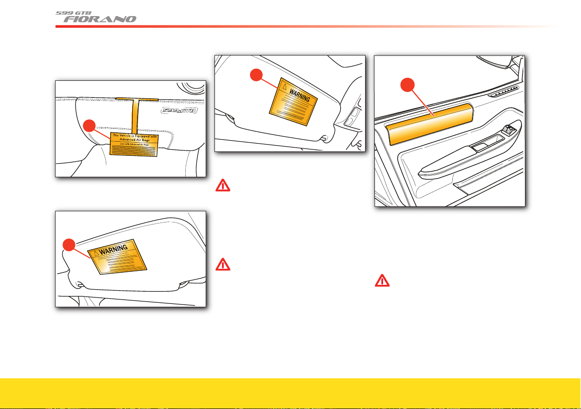
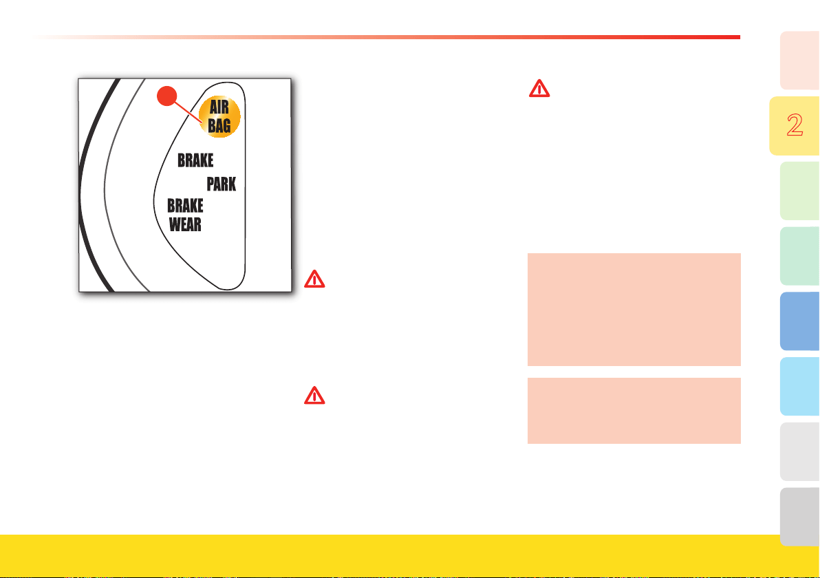
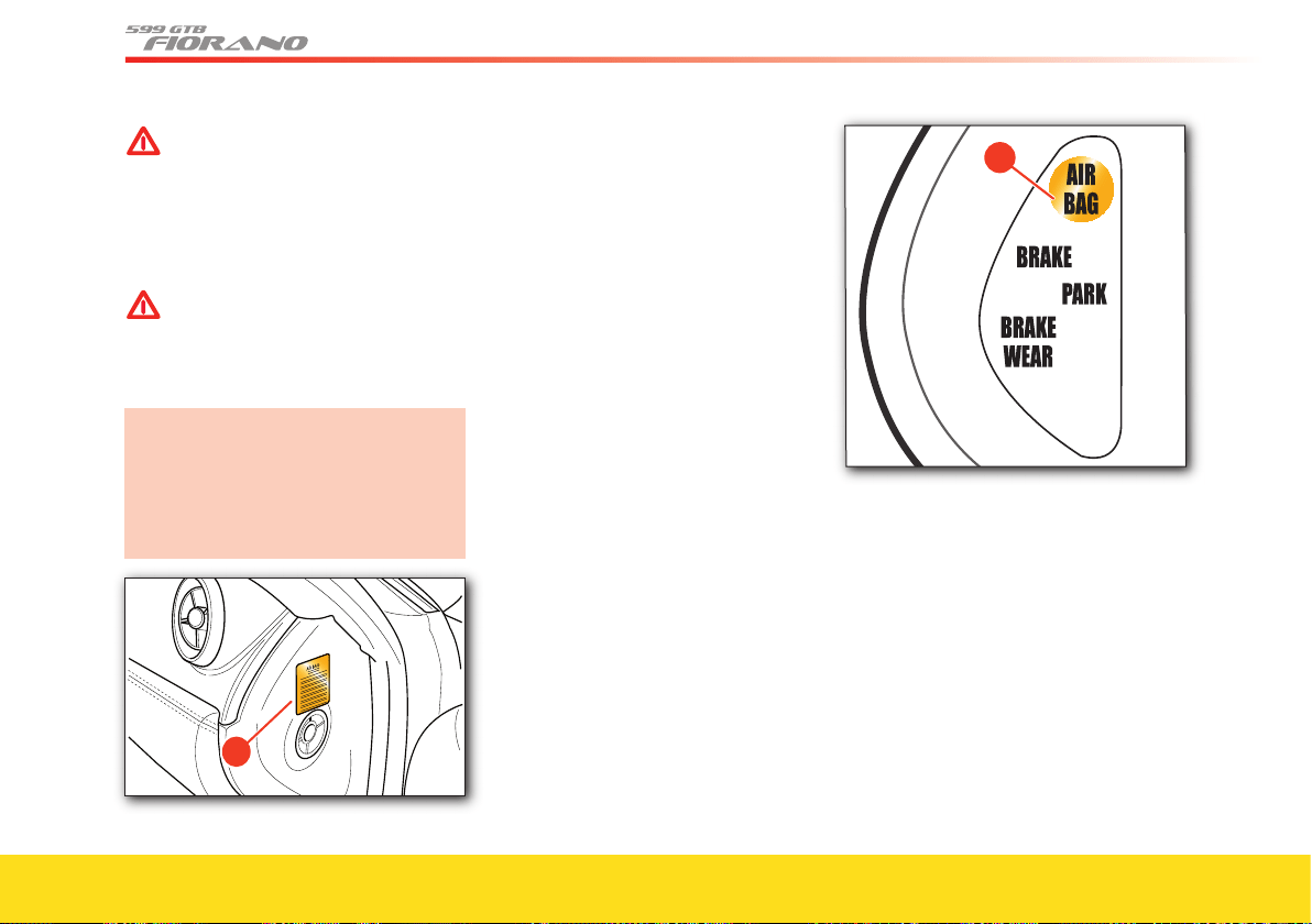
The label E , on the right-hand side of the
dashboard, bears the airbag system
expiration date. When this expiration date
is approaching, contact your Authorized
Ferrari Dealer in order to have the
system replaced.
�
44
The label F on the dashboard can be
removed.
�
The labels G and H indicate the presence
of the airbag system.
�
�
Side Airbag
WARNINGWARNING
The airbags are not a substitute for
the seat belts. Correct use of the seat
belts, with the supplementary action
of the side bags, will provide
protection in the event of a lateral
collision.
Side bag system components
WARNINGWARNING
The side bag fi tted on the vehicle
was not designed to reduce the risk
of being hurled out in the event of
vehicle roll-overs.
Your vehicle is equipped with 2 side bags,
one in the driver-side door A, and the
other one in the passenger-side door.
�
Each side bag is composed of a cushion,
wich has been designed to deploy almost
instantaneously in order to protect the
occupant’s head in the event of a side
impact.
WARNINGWARNING
When the ignition key is turned to
position II, the warning light B will
illuminate. If no malfunctioning in
the airbag system is detected, it will
go off after 4 seconds. If the warning
light does not illuminate, if it
remains on or if it illuminates while
driving, contact your Authorized
Ferrari Dealer immediately.
45
8
7
6
5
4
3
2
1
Safety
�
Operation
The side bags are controlled by a
dedicated ECU that has been designed to
activate them when a lateral collision of a
suffi cient force occurs.
In the event of a side collision with an
impact force exceeding the limit set by the
ECU, this will transmit a signal for
activating the pretensioner and the side
bag on the impact side. The airbag will
start infl ating, opening its cover along the
breakage line, until it is fully deployed (in
a few hundredths of a second).
After deployment, the airbag will be
positioned as a protection between the
driver’s or passenger’s head and the
external structures which could go through
the passenger compartment and cause
injury. The airbags defl ate immediately
afterwards.
The side bag activation is not affected by
the front passenger’s height or weight. The
side bag has been designed to activate
whenever the airbag ECU detects a
collision of a suffi cient impact force for
deployment.
WARNINGWARNING
Never travel with your head leaning
out of the window, as your head and
neck would be in the airbag
activation area. In the event of a side
collision, this position would increase
the risk of being hurled out of the
vehicle and would compromise the
protective action of the side bags.
WARNINGWARNING
Never place an object over or near
the airbag covers.
In the event that the airbags are
deployed, these objects would be
projected into the passenger
compartment at very high speed. The
object will be transformed into a
projectile propelled in the passenger
compartment. This could cause
serious injuries.
WARNINGWARNING
Never modify the airbag modules.
Do not damage the airbag modules
(for example pinning something
onto them or pressing objects
against their covers).
If, for any reason, an airbag cover
gets damaged, have the airbag
module immediately checked by
your Authorized Ferrari Dealer.
Activation of a damaged module
could cause serious or fatal injuries.
Please consider that the airbag ECU is
not capable of automatically detecting
damages involving the airbag covers.
Do not cover the upper part of the
driver-door and passenger-door panels
with adhesive tape or material and do
not treat them in any way.
Never remove the door panel. If
required, this operation must be
performed by your Authorized Ferrari
Dealer.
46
WARNINGWARNING
Following activation, the airbag
components can no longer perform
their protective action; therefore,
they cannot be repaired and must be
replaced. After activation of a side
bag, have it replaced by your
Authorized Ferrari Dealer
.
WARNINGWARNING
The airbag modules must be
replaced at the intervals indicated in
the “Warranty and Service Book”
EVEN if the vehicle was NOT
involved in a collision.
The label E, on the right-hand side of
the dashboard, bears the airbag system
expiration date. When this expiration
date is approaching, contact your
Authorized Ferrari Dealer in order to
have the system replaced.
�
Advanced Airbag System
The system includes:
- a 3-point seat belt (lap and shoulder
seat belt) at each seating position,
equipped with a pretensioner, an energy
management system and a seat belt
sensor, which detects when the seat belt
is fastened (see also page 34)
- a dual stage driver’s airbag at the driver
position, located within the steering
wheel (see also page 41)
- a dual stage passenger’s airbag at the
front passenger position, located on top
of the dashboard (see also page 41)
- two remote acceleration sensors, located
in the engine compartment
- a control unit, located on the center
console, in the passenger compartment
- an Occupant Classifi cation System for
the front passenger, located underneath
the passenger seat, including 4 sensors
and a control unit (see also page 50)
�
- a readiness indicator (red warning light
A in the instrument panel) (see also
page 36) also called “airbag failure
warning light”
47
8
7
6
5
4
3
2
1
Safety
- a passenger airbag status indicator
(amber warning light
B “PASSENGER
AIRBAG OFF
” on the roof panel) (see
also page 39)
�
- a multi-function display, which will
temporarily issue a redundant warning
on the passenger airbag status.
Your system is designed to (see also
page 37):
• disable passenger airbag deployment if a
child is sitting in a rearward-facing child
seat on the front passenger seat
• enable passenger airbag deployment if
an adult is sitting on the front passenger
seat
• either disable or enable passenger
airbag deployment if a child heavier
than a typical one-year old child is
sitting on the front passenger seat in a
forward-facing child seat (see also page
50 for more details about Occupant
Classifi cation System)
• disable passenger airbag deployment if
nobody is traveling in the front
passenger seat or if an object is placed
on top of it.
The passenger airbag status can be
monitored by checking the “PASSENGER
AIRBAG OFF
” warning light B. This
warning light will be illuminated if
passenger airbag deployment is disabled,
and will be turned off if passenger airbag
deployment is enabled.
WARNINGWARNING
Do not carry adults in the front
passenger seat if the “PASSENGER
AIRBAG OFF
” warning light is
illuminated, as the passenger airbag
will not deploy in a frontal crash,
thus reducing the system’s ability to
protect the occupant.
WARNINGWARNING
Do not carry children in rearward-
facing child seats in the front
passenger seat if the “PASSENGER
AIRBAG OFF
” warning light is not
illuminated, as the passenger airbag
could deploy in a frontal crash,
seriously injuring or killing the child.
48
The system components are designed to
work together to help provide the
occupant with the most appropriate
protection level, based on crash severity
and front passenger classification:
- The Occupant Classification System will
attempt, based on the weight resting on
the seat, to classify the front passenger
either as a child (see also page 50 for
more details about the Occupant
Classification System), for which airbag
deployment is not appropriate, as it can
result in serious injuries and death, or
an adult (see also page 50 for more
details about the Occupant Classification
System), for which deployment is
appropriate depending on the crash
severity.
The classification system will then
transmit the occupant classification to
the control unit, that will use the
information to enable or disable
passenger airbag deployment (see also
page 50 for more details about the
Occupant Classification System).
- In the event of certain frontal crashes,
the electronic control unit will use the
signal from the remote acceleration
sensors, from the Occupant
Classification System and from the seat
belt sensor to supplement its internal
sensing capabilities. The control unit is
designed to use this signal to determine
whether airbag deployment and
pretensioner activation are required.
- For frontal crashes, based on the angle
and severity of the crash and on the
front passenger classification, the airbag
control unit is designed to determine
whether to or not to:
• deploy the airbags
• deploy the airbags in low energy mode
• deploy the airbags in high energy mode.
- For low severity crashes, the airbag
control unit will not deploy the airbags.
- For crashes of higher severity, the
control unit will deploy the driver airbag
in low energy mode and will use the
signal from the Occupant Classification
System to determine whether to deploy
the passenger airbag in low energy
mode or not to deploy the airbag (if the
front passenger is classified as child it
will not deploy the airbag. If the front
passenger is classified as adult it will
deploy the airbag) (see also page 50 for
more details about the Occupant
Classification System).
- For crashes of even higher severity, the
control unit will deploy the driver airbag
in high energy mode and will use the
signal from the Occupant Classification
System to determine whether to deploy
the passenger airbag in high energy
mode or not to deploy the airbag (if the
front passenger is classified as child it
will not deploy the airbag. If the front
passenger is classified as “adult” it will
deploy the airbag).
If the airbags are deployed, the seat
belt pretensioner will also be activated
for every seating position where the
seat belt is fastened.
The airbag control unit will use the
seat belt status indicated by the seat
belt status sensor in order not to
activate the seat belt pretensioner for
the seating position where the seat belt
is not fastened.
The control unit is also designed to
perform a check of all the electrical
components in the system (including a
self check) upon ignition and periodically
thereafter, until the engine is turned off.
49
8
7
6
5
4
3
2
1
Safety
Upon ignition, the “airbag” red warning
light in the instrument panel illuminates
for a few seconds, to confirm the warning
light functionality (see page 41).
Whenever the control unit detects a fault
in the system, it will illuminate the “airbag”
red warning light in the instrument panel,
to inform the driver that there may be a
system malfunction.
If:
• the “airbag” warning light does not
illuminate at key on (ignition key in
position II)
or
• the “airbag” warning light does not turn
off a few seconds after key ON
or
• the “airbag” warning light illuminates
while the vehicle is in motion
carefully stop the vehicle in a safe place
and contact your Authorized Ferrari
Dealer immediately.
When the “airbag” warning light is
illuminated, the system functionality
may be compromised or disabled.
Improper repair work on the Advanced
Airbag System or one of its
components can render the system
inoperative, or cause unintended
airbag deployment. Work on the
Advanced Airbag System must only be
performed by qualified technicians.
Please contact your Authorized
Ferrari Dealer for repair work on the
Advanced Airbag System of your
vehicle.
Fastening your seat belts is always
necessary, even with advanced airbags.
Front airbags do not substitute the seat
belts. The front airbags are designed to
help increase the efficiency of the seat
belts and supplement the protection
offered by the seat belts in medium to
high severity frontal crashes.
The seat belts must be properly worn
and fastened in order to offer
protection. Refer to page 34 for proper
use of the seat belts.
WARNINGWARNING
Never place an object over or near
the driver’s or passenger’s airbags. In
the event that the airbag is deployed,
it will project any object over it, or
near it, in the passenger
compartment at very high speed. The
object will be transformed into a
projectile propelled in the passenger
compartment. This could cause
serious injuries.
WARNINGWARNING
Seat belts are designed to help
minimize injury severity in the event
of an accident. To help achieve
optimal protection for adults, the
airbags should supplement the seat
belts. Always wear your seat belts
properly fastened.
WARNINGWARNING
Front airbags cannot offer protection
in side crashes, certain front-angular
crashes, roll over events or in
secondary impacts (if a second crash
happens after the airbags have been
deployed in a previous crash). The
seat belts are designed to help
reduce the risk of injuries in roll
over events and secondary front
impacts. A properly fastened seat
belt is needed to help protect
occupants in roll over events and
secondary front impacts.
50
WARNINGWARNING
Front airbags are designed to not be
deployed in low severity frontal
crashes. The seat belts can help
reduce injuries in low severity
crashes. A properly fastened seat belt
is needed to help protect occupants
in low severity frontal crashes.
WARNINGWARNING
To help ensure protection in the
event of a collision, you must be in a
normal seated position with your
back against the seat backrest. The
passenger’s feet must be on the
footrest. The driver’s left foot must be
on the footrest.
WARNINGWARNING
Adjust your seat as far back as
possible, ensuring you can operate
the vehicle controls properly and
comfortably. Keep your hands on the
steering wheel rim, without crossing
them. Placing your hands or arms
inside the rim increases the risk of
hand/arm injuries in the event of a
crash with driver’s airbag deployment.
WARNINGWARNING
Never place your feet on the
dashboard or the instrument panel or
out of the window, as this will
seriously affect the ability of the
system to protect you in the event of
a crash, and can result in induced
injuries in the event of airbag
deployment.
Occupant Classification System
The Occupant Classification System is
designed to (see also page 42):
• disable passenger airbag deployment if a
child that is lighter and smaller than a
typical one-year old child (up to 20.1 lbs
- 9.1 kg and 26 in. - 66 cm) is traveling in
a rearward-facing child seat (see note 1
on page 50) mounted on the front
passenger seat
• enable passenger airbag deployment if an
adult (weighing more than a 103 lbs -
46.7 kg) is sitting on the front passenger
seat
• disable or enable passenger airbag
deployment if a child heavier than a
typical one-year old child is seated on the
front passenger seat
NOTE 1
The functionality of the system has been
verified by Ferrari for all the following
child seats:
Cosco Dream Ride 02-719
Britax Handle with Care 191
Century Assura 4553
Century Smart Fit 4543
Cosco Arriva 02727
Evenflo Discovery Adjust Right 212
Evenflo First Choice 204
Graco Infant 8457
Britax Roundabout 161
Britax Expressway
Century Encore 4612
Century STE 1000 4416
Cosco Olympian 02803
Cosco Touriva 02519
Evenflo Horizon V 425
Evenflo Medallion 254
Safety 1st Comfort Ride 22-400
The status of the passenger airbag will be
indicated by the warning light
“PASSENGER AIRBAG OFF” on the roof
panel:
• when passenger airbag deployment is
disabled, the “PASSENGER AIRBAG
OFF” warning light,
A, will be
illuminated
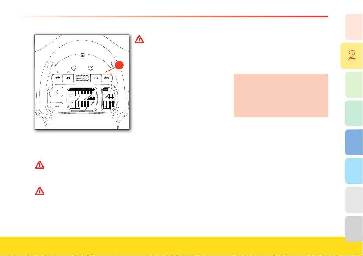
51
8
7
6
5
4
3
2
1
Safety
�
• when passenger airbag deployment is
enabled, the “PASSENGER AIRBAG
OFF” warning light,
A, will NOT be
illuminated.
WARNINGWARNING
Adults should not travel in the front
passenger seat if the “PASSENGER
AIRBAG OFF” warning light is
illuminated.
WARNINGWARNING
Children in a rearward-facing child seat
must not travel in the front passenger
seat if the “PASSENGER AIRBAG OFF”
warning light is not illuminated.
• Install child seats always when the ignition
key is in position
0 (electrical system off).
WARNINGWARNING
Installing a child seat with the
ignition key in position II can result
in induced injuries.
• The extra weight applied on the seat
during child seat installation might delay
correct occupant classifi cation if the
child seat is mounted with the ignition
key in position II
.
After turning the key to ON, the Occupant
Classifi cation System will continuously
attempt to classify every object or person
on the front passenger seat in one of two
categories: “Child” (for which passenger
airbag deployment is dangerous and must
be disabled) or “Adult” (for which
passenger airbag deployment is benefi cial
and must be provided). Occupants or
objects lighter than a typical one-year old
child sitting on a child seat (including an
empty seat) will be classifi ed as “child”.
Occupants or objects heavier than a
typical one-year old child will be classifi ed
as “adult”.
If the Occupant Classifi cation System
identifi es the front passenger as a child,
passenger airbag deployment will be
disabled and the “PASSENGER AIRBAG
OFF” warning light, A, on the roof panel
will be illuminated.
If the Occupant Classifi cation System
identifi es the front passenger as an
“adult”, passenger airbag deployment will
be enabled and the “PASSENGER
AIRBAG OFF
” warning light, A, will not
be illuminated.
The system does not disable the front
passenger seat belt pretensioner (also
known as emergency tensioning
device).
The system does not disable the front
passenger side bag.
When the key is turned to ON, the system
will require a few seconds to classify the
passenger on the front seat. As long as the
system is in the process of classifying the
occupant, the default setting will be child,
to avoid the risk of injuring a child during
this time.
If the Occupant Classifi cation System
identifi es a change in the classifi cation of
the front passenger after the vehicle is
started (for example, if the driver stops
without turning off the engine to allow a
front passenger to get in or get out), the
system will update the passenger airbag
status and the “PASSENGER AIRBAG
OFF” warning light status accordingly.
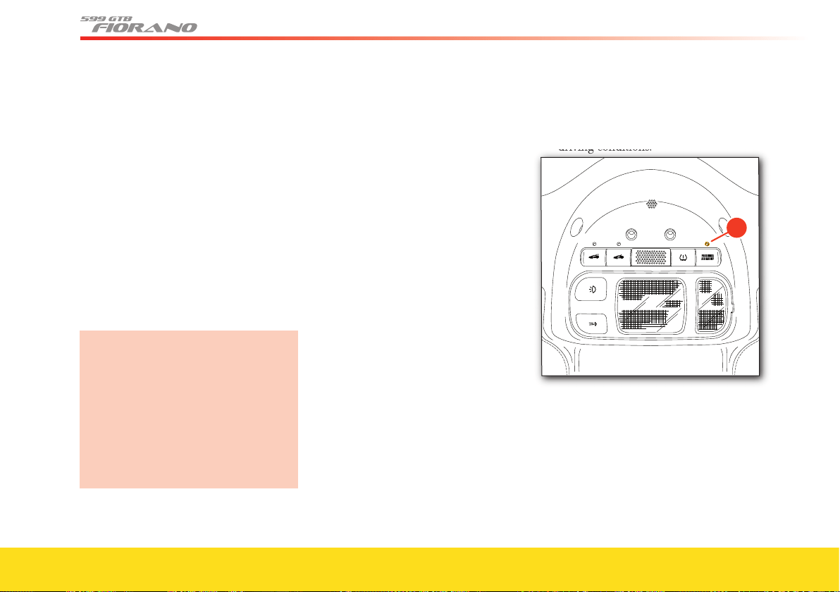
52
Please note that the system may take a few
seconds to update the front passenger
classifi cation when the passenger status
changes.
If the Occupant Classifi cation System
recognizes an internal error, it will signal
the airbag control unit that there may be
a malfunction, and the control unit will
attempt to:
• illuminate the “airbag” red warning light
on the instrument panel
• disable passenger airbag deployment to
avoid the risk of injuring a child, lacking
a certain occupant classifi cation
• illuminate the “PASSENGER AIRBAG
OFF
” warning light on the roof panel.
Please note that when the “airbag”
warning light is illuminated, there may
be an error also in the central control
unit, and the system might not be able
to perform as designed.
Driving carefully, stop the vehicle in a
safe place and contact your Authorized
Ferrari Dealer immediately if the
“airbag” red warning light on the
instrument panel illuminates.
The system’s ability to classify the
occupant in the correct class can be
reduced if:
1. An adult transfers part of his/her
weight onto other objects other than
the seat, e.g.,:
- by leaning on the armrest
- by leaning on the center console
- by putting his/her feet on the
dashboard or out of the window
- by leaning on a headrest.
2. An object is tucked underneath the
seat or behind it.
3. An object is tucked between the seat
and the center console, or between the
seat and the door panel.
4. An adult is extremely light (less than
102.9 lbs - 46.7 kg).
5. A child has outgrown the weight for
which rearward-facing child seats are
appropriate.
6. An object is stored behind the
passenger seat and contacts the seat.
7. Weight is placed on the front
passenger seat.
8. The front passenger seat is tampered
with.
9. A child seat contacts the dashboard.
10. A child seat is too heavy (see note 1
on page 50).
11. The seat backrest contacts the rear shelf.
A button provided on the rear shelf will
move the seat backrest forward.
12. The vehicle is used in certain extreme
driving conditions.
driving conditions.
�
If the “PASSENGER AIRBAG OFF”
warning light, A, illuminates when an adult
is seated on the front passenger seat:
• slow down and instruct the front
passenger not to lean on the vehicle
interiors.
If the “PASSENGER AIRBAG OFF
”
warning light, A, is still illuminated:
• driving carefully, stop the vehicle in a safe
place
53
8
7
6
5
4
3
2
1
Safety
• check for objects tucked underneath the
seat or behind it
• check for loose objects on the passenger
floor, either in front or behind the front
seat.
If the “PASSENGER AIRBAG OFF”
warning light, A, is still illuminated, call
for assistance.
WARNINGWARNING
Do not carry adults in the front
passenger seat if the “PASSENGER
AIRBAG OFF” warning light is
illuminated, as the passenger airbag
will not deploy in a frontal crash,
thus reducing the system’s ability to
protect the occupant.
If the “PASSENGER AIRBAG OFF”
warning light, A, does not illuminate when
a child in a rearward-facing child seat is
seated on the front passenger seat, drive at
reduced speed.
If the “PASSENGER AIRBAG OFF”
warning light, A, is still not illuminated:
• driving carefully, stop the vehicle in a
safe place
• check for contact between the child seat
and the dashboard or other vehicle
interiors
• check for objects tucked underneath the
seat or behind it
• check for loose objects on the passenger
floor, either in front or behind the front
seat
• verify that the child has not outgrown
the weight for which rearward-facing
child seats are appropriate. If this is the
case, install a forward-facing child seat
appropriate for the child weight
• if the child has not outgrown the weight
for which rearward-facing child seats are
appropriate, try installing a lighter child
seat, if available.
If the “PASSENGER AIRBAG OFF”
warning light, A, is still not illuminated:
turn off the engine (key to position
0)
and wait a few seconds.
Restart the engine (see page 102 - 107).
If the “PASSENGER AIRBAG OFF”
warning light, A, is still not illuminated
call for assistance.
WARNINGWARNING
Do not carry children in rearward-
facing child seats in the front
passenger seat if the “PASSENGER
AIRBAG OFF
” warning light is not
illuminated, as the passenger airbag
could deploy in a frontal crash,
causing serious injury or death.
WARNINGWARNING
The front passenger’s seat and its
control unit are part of the advanced
airbag system. Never have your seat
tampered with, as this can result in a
system malfunction, which could
cause serious injuries or death.
WARNINGWARNING
Repairs on the front passenger seat
must only be performed by trained
technicians at an Authorized Ferrari
Dealer.
When a passenger is sitting in the front
seat:
• always check that no objects are tucked
underneath the seat or behind it
• always check that no objects are
loose on the floor, either in front, or
behind the seat
• check that no objects contact the seat
• make sure the “PASSENGER
AIRBAG OFF” warning light status is
appropriate for the type of occupant
(ON for a child in a rearward-facing
child seat, OFF for an adult, either
ON or OFF for a child properly
secured in a forward-facing child
restraint system).
WARNINGWARNING
Not following the above instructions
can result in serious injuries or death
in the event of a crash.
54
ABS
This is a safety device which is designed
to activate in order to help prevent wheel
locking if the driver depresses the brake
pedal too sharply, especially under poor
grip conditions.
The system is composed of:
- an electro-hydraulic unit
- an electronic brake-force distributor
(EBD)
- four speed sensors on the wheels,
incorporated in the bearings.
These features add to the vehicle’s
standard braking system, without
changing its characteristics.
When the ABS is activated, during
emergency braking or under poor grip
conditions, the driver will perceive a
“pulsation” of the brake pedal. Hold the
brake pedal pressed to continue the
braking action.
When one of the wheels starts locking, the
hydraulic control unit controls the braking
system by running a 3-phase cycle:
- reduction (if necessary)
- maintenance
- pressure increase in the hydraulic circuit.
If braking with ABS activation occurs,
these adjustment phases will be repeated
in cycles until the vehicle comes to a stop
or the pressure on the pedal decreases.
In addition, the system offers the
following advantages:
- driving stability (no skidding), even in
the event of sharp braking approaching
wheel locking.
- maneuverability (no side-skidding on
sharp turns).
This means that even when an emergency
situation requires sudden braking, the
driver can avoid obstacles, or brake on a
curve, without affecting the vehicle
stability.
WARNINGWARNING
The ABS system features remain
unaltered as long as the speed limit
for the tire side grip is not exceeded.
When this limit is exceeded, vehicle
skidding cannot be avoided.
- Optimal braking distance:
depending on the type of road surface,
the braking distance may be reduced by
as much as 40%.
WARNINGWARNING
The ABS system does NOT exempt
the driver from driving carefully and
responsibly at all times.
The ABS system cannot compensate
for driving at speeds that are
excessively high for certain traffic or
road surface conditions, worn tires,
worn components in the braking
system or driving errors.
The ABS system has been designed for
the sole purpose of assisting the driver in
controlling braking under extreme
conditions, in which he could instinctively
cause the wheels to lock.
CST
CST is Ferrari’s acronym for Stability and
Traction Control. The CST is composed of
two main systems:
VDC Vehicle Dynamics Control,
performed through the braking
system and engine torque
F1-Trac Traction control, performed
through engine torque
modulation, depending on
maximum grip on the road
and of secondary systems that are always
active, such as the ABS, EBD, etc.
To help provide optimal control in different
driving and grip conditions, four different
setting levels have been designed:
55
8
7
6
5
4
3
2
1
Safety
- Level 1: helps ensure stability and
maximizes traction on every type of road
surface, both in low (“Manettino” set to
Low Grip position) and very low
(“Manettino” set to ICE) grip conditions,
by means of engine and brake control (in
this condition, the standard ASR system
activates instead of the F1-Trac function).
- Level 2: helps ensure stability and
maximizes traction only in dry- to high-
grip conditions (“Manettino” set to
SPORT) optimizing engine and brake
control.
- Level 3: enhances the racing features of
the vehicle, helps provide but does not
ensure a good level of stability
(“Manettino” set to RACE) by reducing
engine control to a minimum and making
the best use of brake control.
WARNINGWARNING
RACE mode must be used only on
race tracks.
- Level 4: CST off (position
).
Stability is not ensured, but all the other
features always present in the other
settings, such as the ABS and EBD,
remain active. When the brake pedal is
depressed, the VDC system reactivates.
When the brake pedal is relased, the
VDC system
deactivates.
F1-Trac
F1-Trac is directly derived from Ferrari’s
expertise in F1 vehicles. This system is
designed to optimize traction by
controlling engine power delivery.
F1-Trac
is faster and more accurate than
the traditional control systems, and is
capable of delaying and minimizing
engine torque adjustments, in order to
help ensure the desired trajectory.
The system estimates the maximum
available grip in advance, by continuously
monitoring the relative wheel speed and
using an auto-adaptive operation logic.
Comparing this information with the
vehicle dynamics model stored in the
control system, F1-Trac optimizes the
vehicle behavior by controlling engine
torque delivery.
F1-Trac does not work when the
"Manettino" is set to CST off.
Tire pressure and temperature
monitoring system
The vehicle is equipped with a system that
monitors the tire pressure and
temperature by means of special sensors
secured inside the wheel rims, in position
with the inflation valve. These sensors
transmit a signal that is detected by the
antennas on the car body, behind the
gravel guards, that are connected to the
ECU.
The system can momentarily
experience radio-electric interference
emitted by devices using similar
frequencies.
The ECU processes this information and
transmits, via the CAN line, a series of tire
pressure and temperature data as well as
any system errors to the instrument panel.
The signal transmitted by the ECU
activates some symbols on the TFT display,
with two priority levels: a soft warning
(SW) if the pressure reduction in relation
to the rated pressure is greater than 2.9
psi (0.2 bar), and a hard warning (HW) if
it is greater than 5.8 psi (0.4 bar) or if
there is a dynamic reduction of over 2.9
psi (0.2 bar/min.)
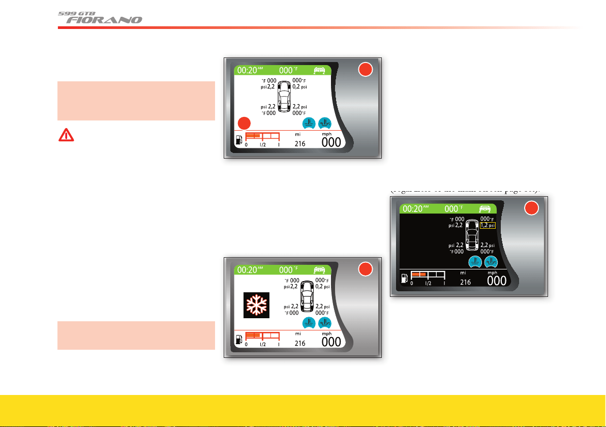
56
The calibration button is positioned on
the inside roof panel (see page 94).
After tire replacement or infl ation, the
system must be calibrated using the
relative button on the roof panel.
WARNINGWARNING
The system warns the driver that the
tire pressure has decreased. However,
this does NOT exempt the driver
from periodically checking that the
tires are infl ated to the indicated
pressure.
In addition, the system is UNABLE to
warn the driver of sudden damage to
the tires caused by external objects/
agents (e.g., nails, stones, etc.).
Viewing messages on the “TFT” display
By pressing the DISP
button or using the
Menu function, the driver can access the
TIRES information screen page, which
shows the pressure and temperature
values for each tire, as in the following
example 1.
The TFT does not display any warning
messages related to tire temperature.
1
�
The TIRES information page can also be
set as main screen page (see page 83).
When indication by event occurs (e.g.,
malfunctions with priority levels 1/2, see
page 86), the page is displayed as in the
following example
2 for a time equal to
the entire malfunction display cycle.
Warning
ice hazard
2
When the display cycle ends, the TIRES
screen page becomes available again and
the summary symbol for the malfunction
is displayed in the specifi c area
A (screen
page
1), until the malfunction is corrected.
Low pressure
When the on-board instrument panel
receives the signal from the tire pressure
ECU that the pressure level of one tire is
below the
alarm threshold, screen page 3
will be displayed
(regardless of the main screen page set).
(regardless of the main screen page set).
3
If the tire pressure value of more than one
tire is below the alarm threshold, the
following screen page
4 will be displayed.
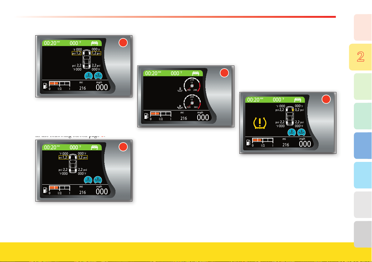
57
8
7
6
5
4
3
2
1
Safety
�
After the display time has elapsed, the rel-
ative screenpage disappears.
Subsequently, if the TIRES
screen page is
active, the TFT display will be viewed as
in the following screen page
5.
in the following screen page
5
.
�
Upon the next engine starting, if the
failure persists, the relative warning light
will illuminate on the display.
The system may not know which wheel is
originating the malfunction and therefore
is not capable of indicating the wheel
involved. In this case, screen page
6 will
be displayed.
�
After the display time has elapsed, the rel-
ative screenpage disappears.
The TIRES screen page that shows the
pressure of each tire cannot be recalled
by the user.
Also in this case, if the pressure malfunction
persists, upon the next engine starting the
display will show the relative screen page.
Subsequently the symbol will be viewed in
the area dedicated to the warning lights,
until the situation is corrected, as is the case
for other priority level 2 malfunctions.
Tire punctures
When the on-board instrument panel
receives the signal from the tire pressure
ECU that the pressure level of one or
more tires is below the alarm threshold,
screen page 7 is displayed. At the same
time, the warning light on the instrument
panel illuminates (see page 93).
7
The same display logic is applied for the
other priority level 0 malfunctions, until
the situation is corrected and the system is
recalibrated (after turning the key to OFF
and then back to ON).
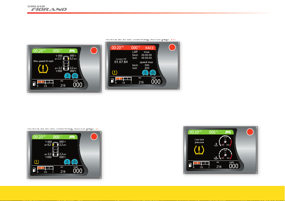
58
For vehicles equipped with “Run Flat”
tires, screen page 7 will be displayed four
times alternately with screen page 8.
8
Subsequently, the symbol will be
displayed in the area dedicated to the
warning lights A, until the situation is
corrected, as is the case for other
priority
level 2
malfunctions. If the TIRES screen
page is active, the TFT display will be
viewed as in the following screen page 9.
viewed as in the following screen page
9
.
�
If, instead, the TIRES screen page is not set
as main page, the TFT display will be
viewed as in the following screen page
10.
viewed as
in the following screen page
10
.
The instrument panel will calculate the
residual fuel range and will display the same
information after 31 mph (50 km).
When a tire is punctured, if you drive more
than 62 mi (100 km) screen page
7 will be
displayed or, if the vehicle speed exceeds 50
mph (80 km/h) screen page 7 or 8 will be
displayed, according to the display logic of
other priority level 0 malfunctions.
After the key has been turned to OFF and
then back to ON, the on-board panel must
display the screen page “System not
calibrated” (see page 59). The TIRES
screen page cannot be recalled by the user.
If, during the display cycle of priority level
0
malfunctions (normal tire puncture), the
driver presses the MODE button, the Set-
up Menu is accessed immediately, as for
other priority level
0 malfunctions.
If, instead, during the above mentioned
priority level 2 cycle (RUN-FLAT tire
puncture, when the speed limit has not
been exceeded and the tire conditions still
permit to travel), the driver presses the
MODE button, screen page
9 will be
displayed. The multi-function symbol will
be displayed in the warning light area, as for
other priority level 2 malfunctions, until the
situation is corrected and the system is
recalibrated.
The system may not know which wheel is
originating the malfunction and therefore
is not capable of indicating the wheel
involved. If the TIRES screen page is set
as the main page, screen page 11 will be
displayed.
��
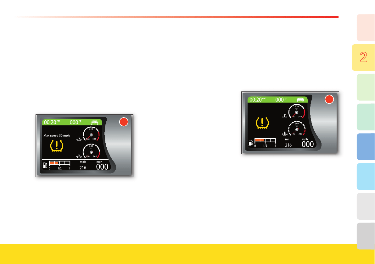
59
8
7
6
5
4
3
2
1
Safety
If the TIRES screen page is not set as the
main page, when the display cycle has
been completed the symbol will be
viewed in the warning light area A
(priority level 2).
The TIRES screen page that shows the
pressure of each tire cannot be recalled
by the user.
For vehicles equipped with “Run Flat”
tires, screen page 11 will be viewed four
times, alternating with screen page 12.
Subsequently, the symbol will be
displayed in the area dedicated to the
warning lights A, until the situation is
corrected, as is the case for other
priority
level 2
malfunctions.
If the TIRES screen page is not set as the
main page, when the display cycle has
been completed the symbol will be
viewed in the warning light area A
(priority level 2).
The instrument panel will calculate the
residual fuel range and will display the same
information after 31 mph (50 km).
When a tire is punctured, if you drive more
than 62 mi (100 km) screen page
11 will be
displayed or, if the vehicle speed exceeds 50
mph (80 km/h) screen page
11 or 12 will
be displayed, according to the display logic
of other priority level 0 malfunctions
.
Following a key-off / key-on cycle, the on-
board panel must display the screen page
“System not calibrated” (see page 59).
The TIRES screen page cannot be
recalled by the user.
System not calibrated
If the system has not been calibrated or
following replacement of one or more
tires, screen page 13 will be displayed.
At the same time, the warning light on the
instrument panel starts fl ashing (see page.
93). Then the warning light remains on until
the system is calibrated.
Subsequently, the screen page reappears
with the “icon” symbol in the area
dedicated to the warning lights (as for
other priority level 2 malfunctions).
The system can be calibrated by pressing
the specifi c button for a time ranging
between 4 and 10 seconds (see page 94),
with the key turned to on. When the
button is pressed and the next calibration
procedure has been accepted, screen page
14 appears for 5 seconds.
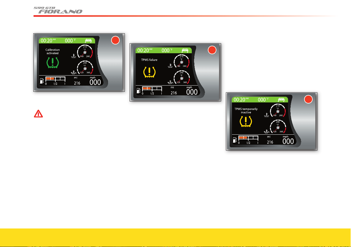
60
The TIRES screen page cannot be
recalled by the user.
WARNINGWARNING
Before calibrating the system, make
sure that the tire pressures
correspond to the indicated pressure
values (see page 26-27). If this is not
the case, the system may issue wrong
low pressure indications.
Tire pressure monitoring system failure
Screen page 15 is displayed in the
following cases:
- malfunction in the circuit and/or wiring
leading to the ECU
- signal reception failure by one or more
sensors due to malfunctioning, damaged
or fl at battery
- ECU malfunctioning.
At the same time, the warning light on the
instrument panel starts fl ashing (see page
93). Then the warning light remains on until
the system is calibrated.
The TIRES screen page cannot be
recalled by the user.
System temporarily not active
When one of the following conditions
occurs:
- excessively high temperature
- during the calibration
- radio frequencies which disturb the
wheel sensor signal
screen page
16 is displayed.
At the same time, the warning light on the
instrument panel starts fl ashing (see page
93). Then the warning light remains on until
the system is calibrated.
Subsequently, the screen page reappears
with the “icon” symbol in the area
dedicated to the warning lights A (as for
other priority level 2 malfunctions).
The TIRES screen page cannot be
recalled by the user.
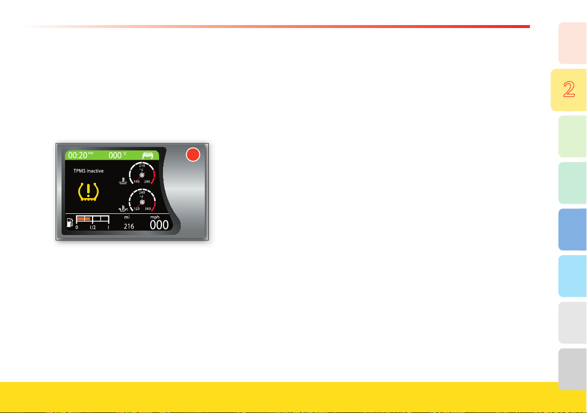
61
8
7
6
5
4
3
2
1
Safety
System not active
After turning the key to ON, if the system
was deactivated by means of the
diagnostic tester, screen page 17 will be
displayed.
At the same time, the warning
light on the instrument panel starts fl ashing
(see page 93). Then the warning light
remains on until the system is calibrated.
Subsequently, the screen page reappears
with the “icon” symbol in the area
dedicated to the warning lights A (as for
other priority level 2 malfunctions).
The TIRES screen page cannot be
recalled by the user.

1. General
2. Safety
3. About your Vehicle
4. Advice for Emergency Situations
5. Care of the Vehicle
6. Table of Notes
7. Glossary
8. Index
Overview of controls
Opening and closing
Lighting
Instruments and gauges
Roof panel controls
Controls on the steering wheel
Windshield washer/wipers
and headlight washer
Driving the vehicle
Ignition switch
Handbrake lever
Adjustments
Air conditioning
and heating system
Passenger
compartment accessories
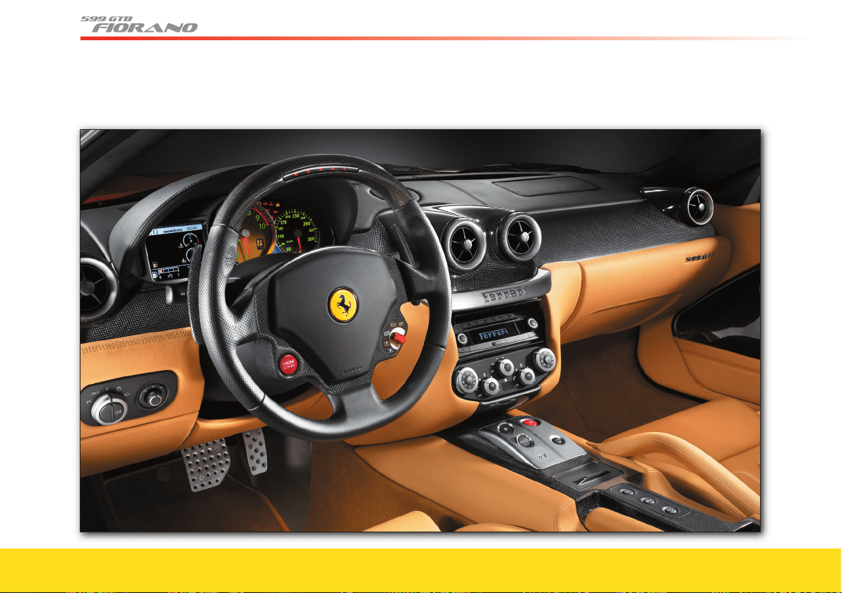
64
Overview of controls
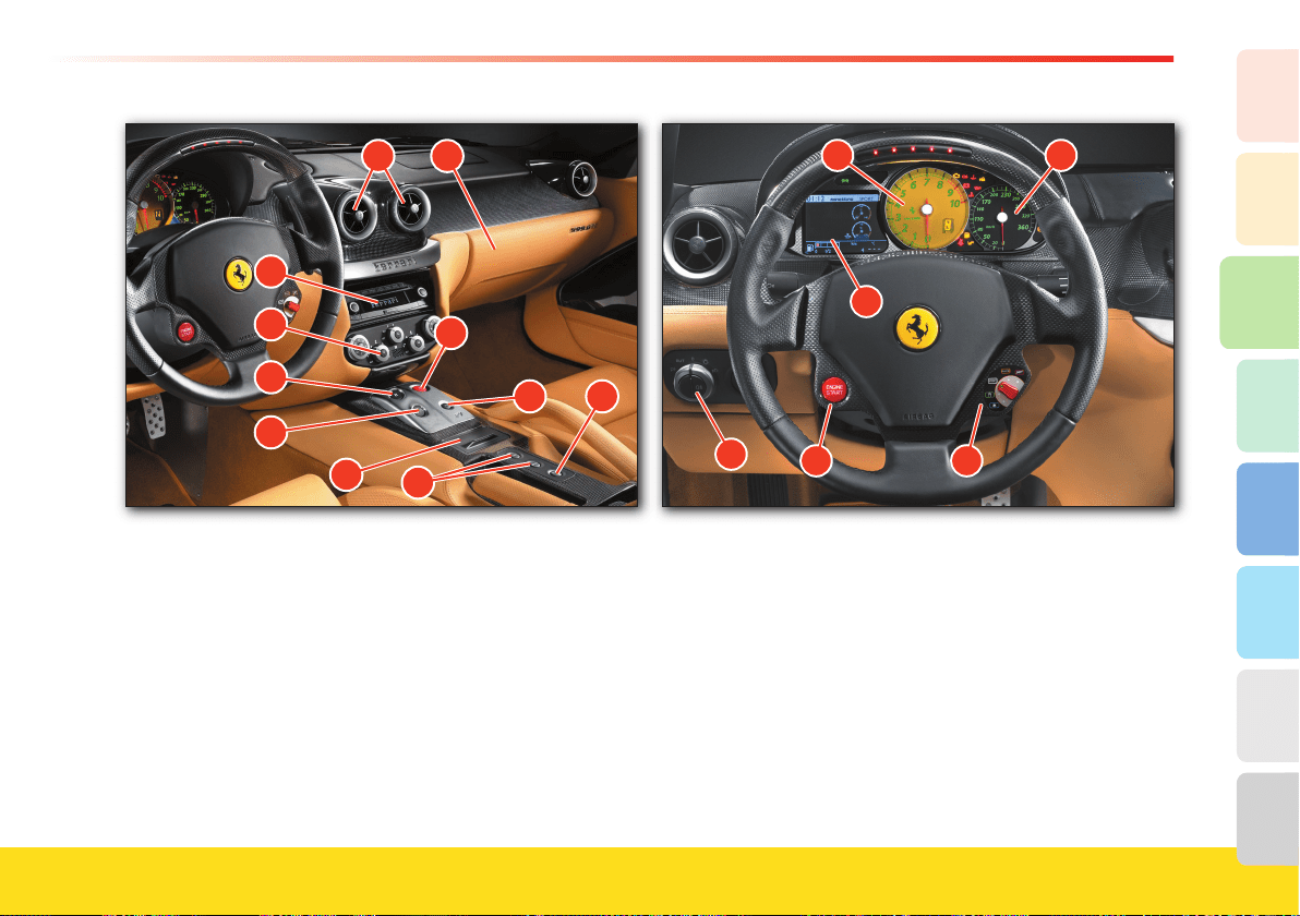
65
About your vehicle
2
1
3
8
7
6
5
4
Ref. Control Page
1
Adjustable center air vents 125
2
Glove compartment 125
3
Hazard warning lights control 77
4
Glove compartment opening button 126
5
Parking sensor control 109
6
Controls for door locking and unlocking 68
7
Ashtray 127
8
F1 gearbox Auto button (*) 106
9
F1 gearbox reverse button (*) 101
Ref. Control Page
10
Air conditioning and heating system controls 122
11
Car radio system -
12
Light switch 73
13
“ENGINE START” button 95
14
“Manettino” control 95
15
“TFT” display 79
16
Tachometer 90
17
Electronic speedometer 90
(*) Only for “F1” gearbox version
1
2
11
10
9
8
7
6
5
4
3
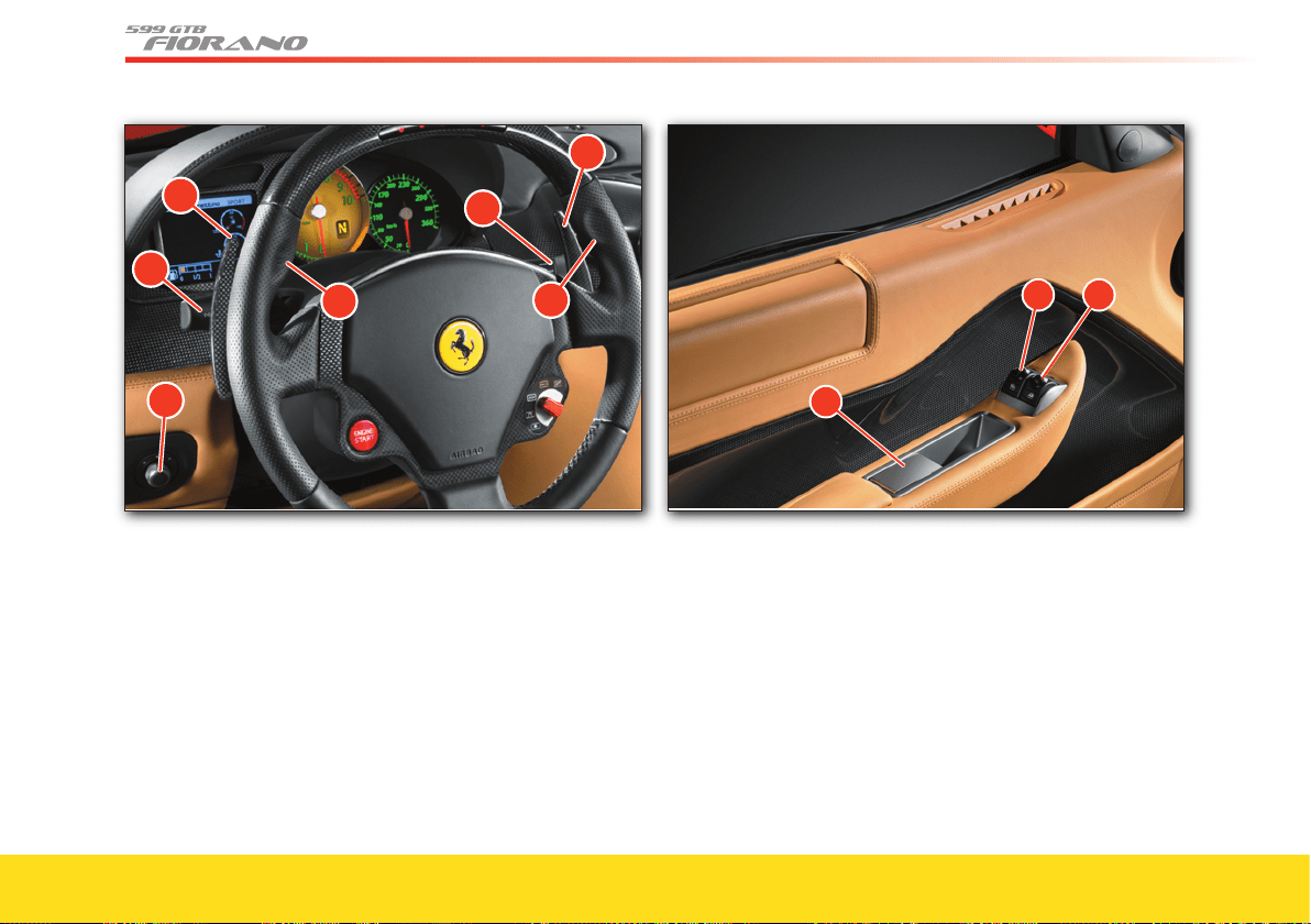
66
Ref. Control Page
18
External rear-view mirrors adjustment 121
19
External lights and direction indicators control lever 73, 76
20
“DOWN” gearshift lever (*) 97
21
Horn control 97
22
Windshield washer/wipers/headlight washer control
lever
97
23
“UP” gearshift lever (*) 97
Ref. Control Page
24
Driver-side power window control 72
25
Passenger-side power window control 72
26
Control for door opening from the inside 69
(*) Only for “F1” gearbox version
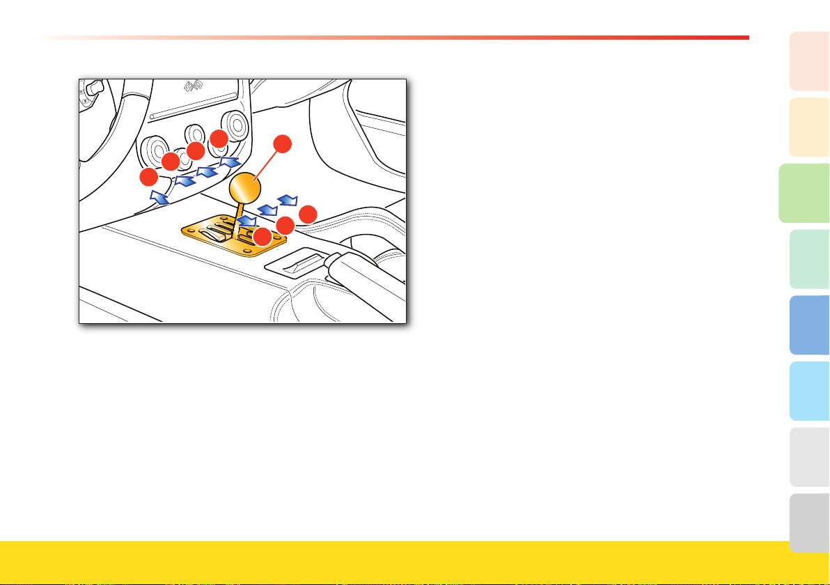
67
About your vehicle
2
1
3
8
7
6
5
4
Ref. Control Page
27
Mechanical gearshift lever 107
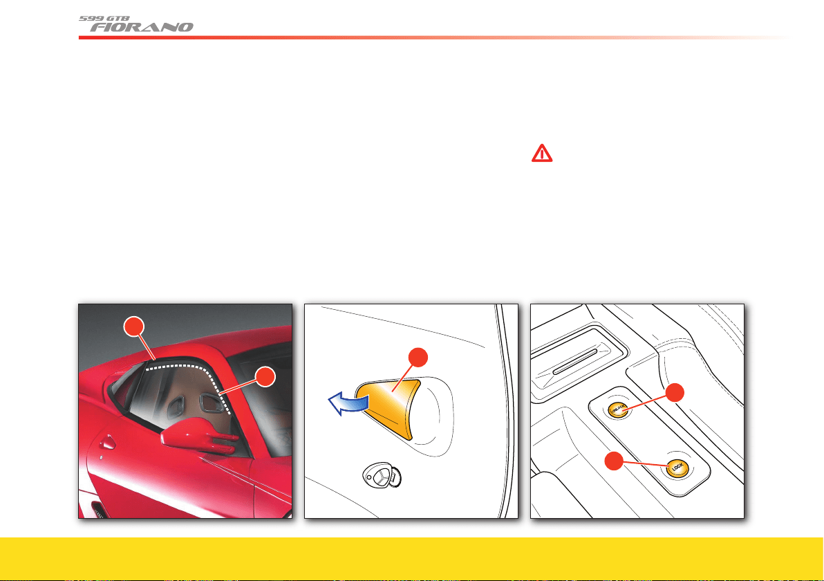
68
Opening and closing
Doors
Introduction
When a door is opened or closed, the
window automatically moves down by
approximately 2 centimeters, “
preset
position” A, in order to avoid damaging
the “upper weather strip”. When the door is
closed, the window automatically moves
back up, position B, until it meets the
“upper weather strip”.
A
B
Opening from the outside
Using the remote control, deactivate the
alarm and the central door locking system,
or turn the key in the lock to deactivate
the central door locking system.
When pulling the handle
C to open the
door, the window moves down by
approximately 2 centimeters. When the
door is closed, it will move back up until
it meets the weather strip.
C
Locking and unlocking the doors from the inside
Press the “LOCK” D button for locking
both doors and press the “UNLOCK”
E button to unlock them.
WARNINGWARNING
Always check that the doors are
properly closed to prevent them
from opening while driving.
D
E
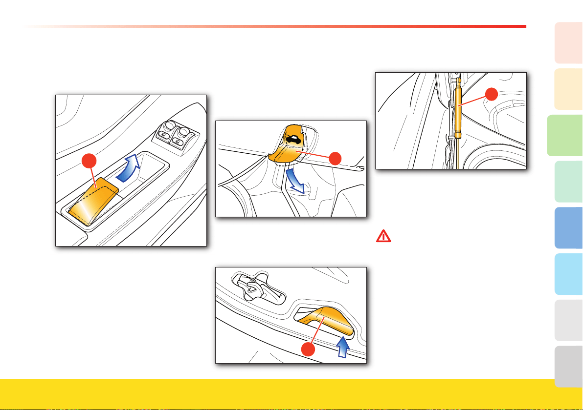
69
About your vehicle
2
1
3
8
7
6
5
4
Opening the doors from the inside
Pulling the handle F to open the door, the
window will lower to the
“preset position”.
F
When the door is closed, it will move back
up until it meets the “upper weather strip”.
If the handle F is pulled without opening
the door, the window will lower to the
“preset position” but, after 2 seconds, if the
door is not opened, the window will rise
to the “upper weather strip”.
Therefore, to open the door, release the
handle F and pull it again.
Engine compartment lid
Opening
To open the engine compartment lid, pull
the lever A found beneath the steering
column.
A
Release the lever B that retains the lid.
This lever is located in the front section of
the vehicle, in the center position.
B
The lid is held open by two gas struts C.
C
Closing
Lower the lid until it is closed and press
down near the lock until you hear it click
in place.
WARNINGWARNING
Always check that the lid is properly
closed to prevent it from opening
while driving.
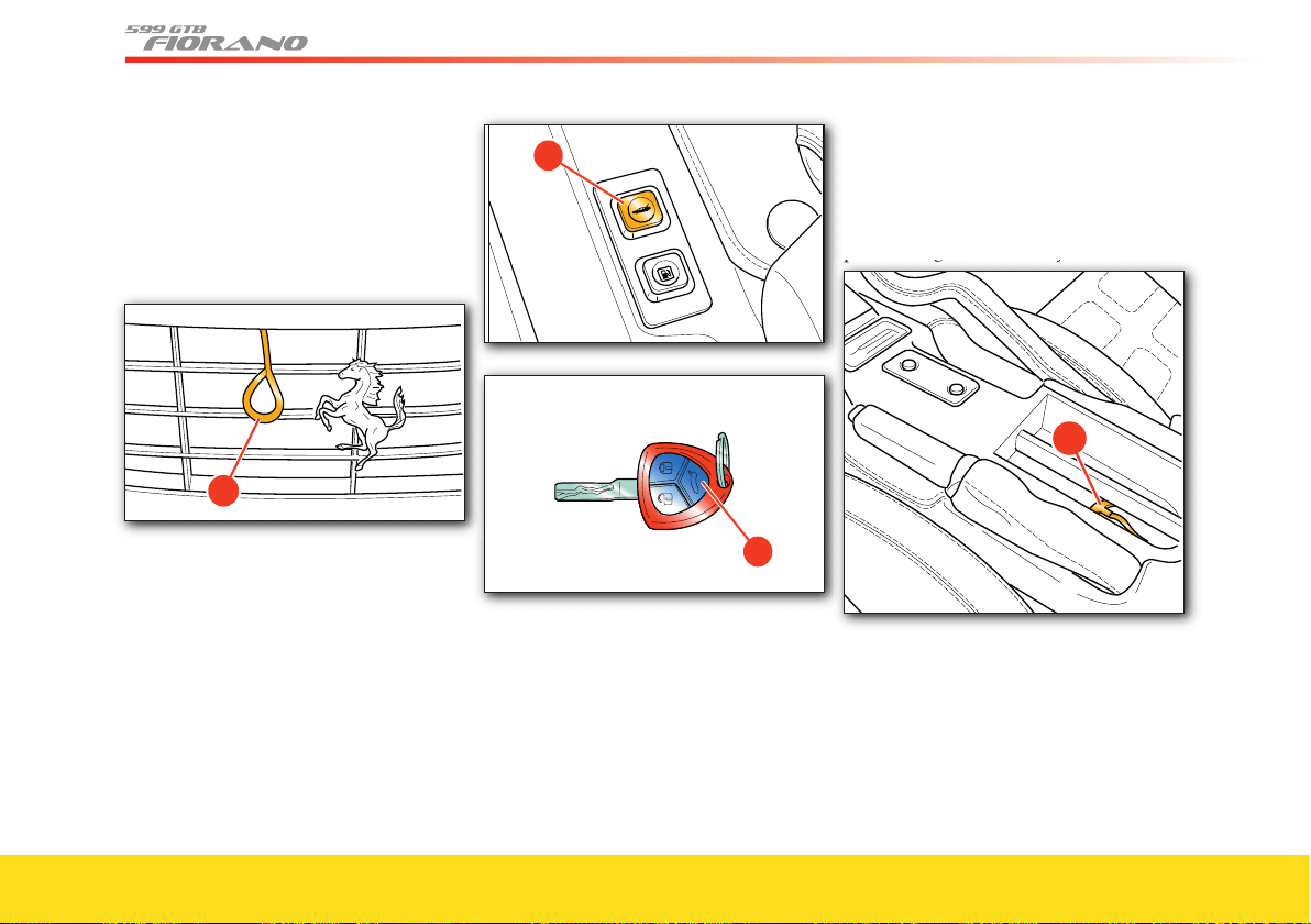
70
Emergency Opening/Closing
If the lid opening lever is not functioning,
insert your hand through the fi ns of the
front grill and push until you remove the
protective cover from its seat. Grip the
ring D with your fi ngers and pull it
outwards.
D
Luggage compartment lid
Opening
To open the luggage compartment lid,
press button A, or button B on the remote
control, and hold it for more than 2
seconds.
The luggage compartment is illuminated
by an internal light that comes on
automatically when the luggage
compartment lid is opened.
A
�
Closing
Using the grip on the inside, lower the
luggage compartment lid until it touches
the bodywork.
Then press downward on the middle of
the lid until you hear the lock click in
place.
Emergency Opening/Closing
If button A and button B on the key
remote control are not functioning, lift the
trim panel (using the tab) of the pocket-
change tray on the center console, and
pull the ring D of the safety cable.
pull the ring
of the safety cable.
D
Emergency exit from inside the luggage
compartment
If someone remains closed inside the
luggage compartment accidentally, the
luggage compartment lid can be opened
from the inside by pulling the handle
E,
located on the back, right-hand side of
the compartment to the right of the lock.
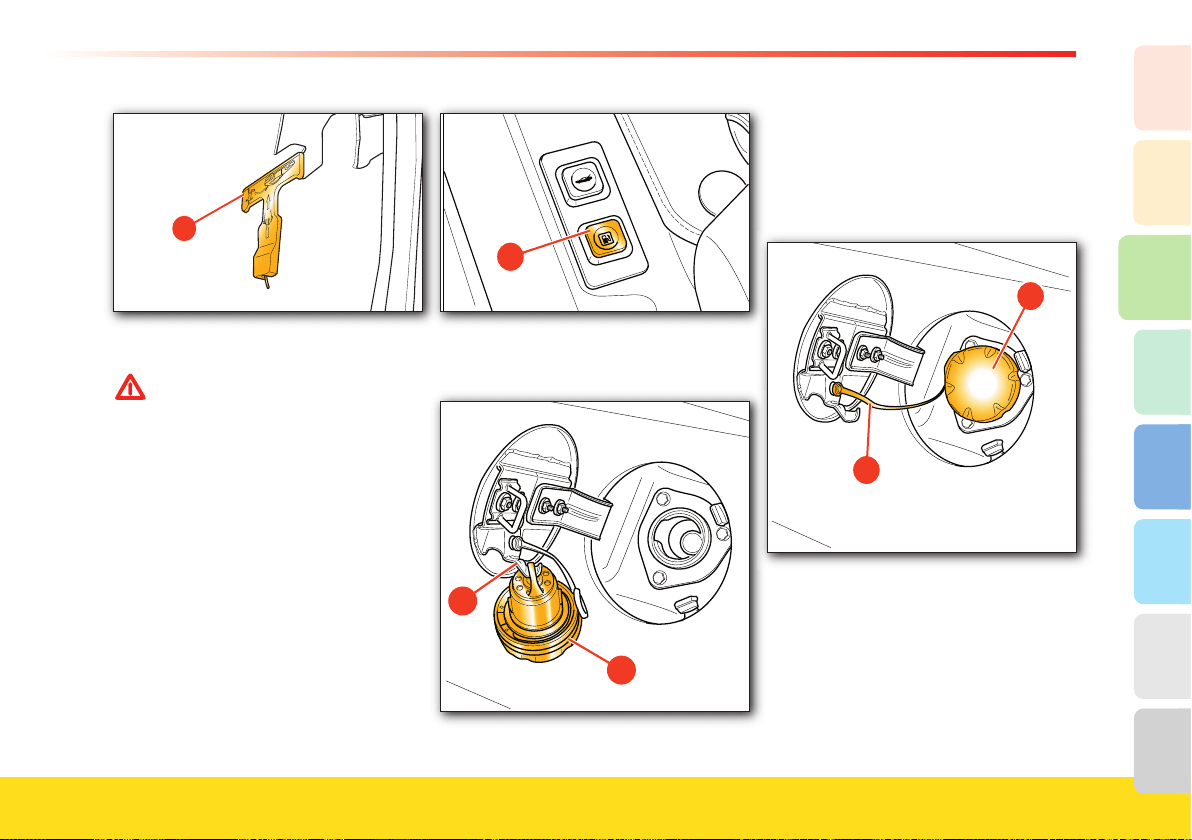
71
About your vehicle
2
1
3
8
7
6
5
4
�
Fuel tank cap and door
WARNINGWARNING
Always turn off the engine during
refueling. Take extreme care when
removing the cap.
Do not smoke or use open fl ames
during refueling.
The following can be harmful for
your health:
- fuel coming into contact with your
skin
- inhaling fuel vapors.
Opening
With the key in position
0, press the
release button A to unlock the fuel tank
door.
A
Unscrew the cap B, rotating it
counterclockwise and hang it on the
hook C.
B
C
Closing
Screw the cap B back on tightly and close
the fuel tank door.
Make sure that the string
D is not hanging
out of the fuel tank door.
D
B
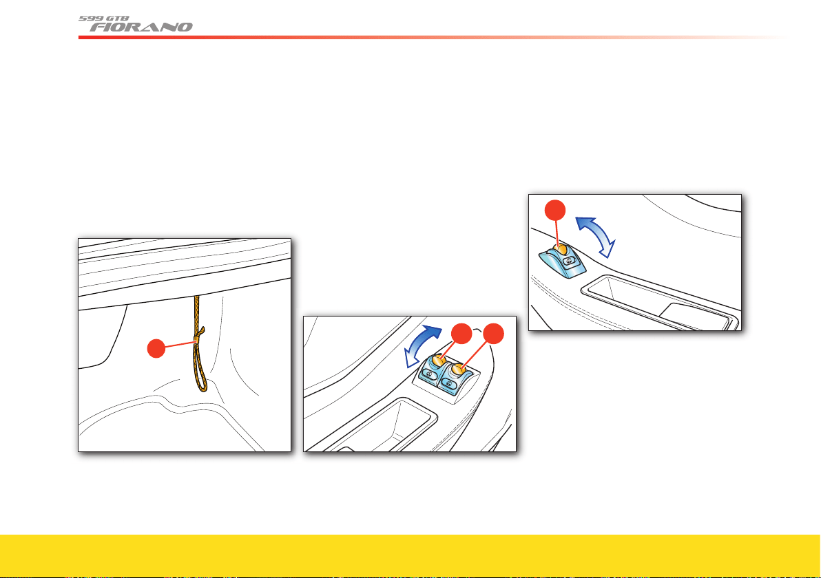
72
Emergency opening
In the event that the button A is
malfunctioning, the lid can be opened
manually by pulling the cable
E, located
on the left-hand side of the luggage
compartment.
�
Power windows
The power windows can only be used
with the ignition key in position II
.
Driver-side power window
Press button A to move the window up or
down. This button allows manual
operation (partial opening/closing) or
automatic operation (complete opening/
closing). Press button
A briefl y, to activate
manual operation. Hold the button down
for a longer time (more than 0.3 seconds)
or press it a second time to activate
automatic operation, so that the window
stops when it reaches the end of its travel.
A
B
The driver side is also equipped with
button B which operates the passenger-
side power window.
Passenger-side power window
Press button C to move the window up or
down.
C
Only manual operation is possible (partial
opening) to raise the window: when
button C is released, the window stops at
the position reached. To lower the
window, automatic operation is also
possible (full opening): if the button is
pressed at length (over 0.3 seconds) the
automatic window operation is activated.
The window will only stop when it
reaches the end of its travel or by pressing
the button again.
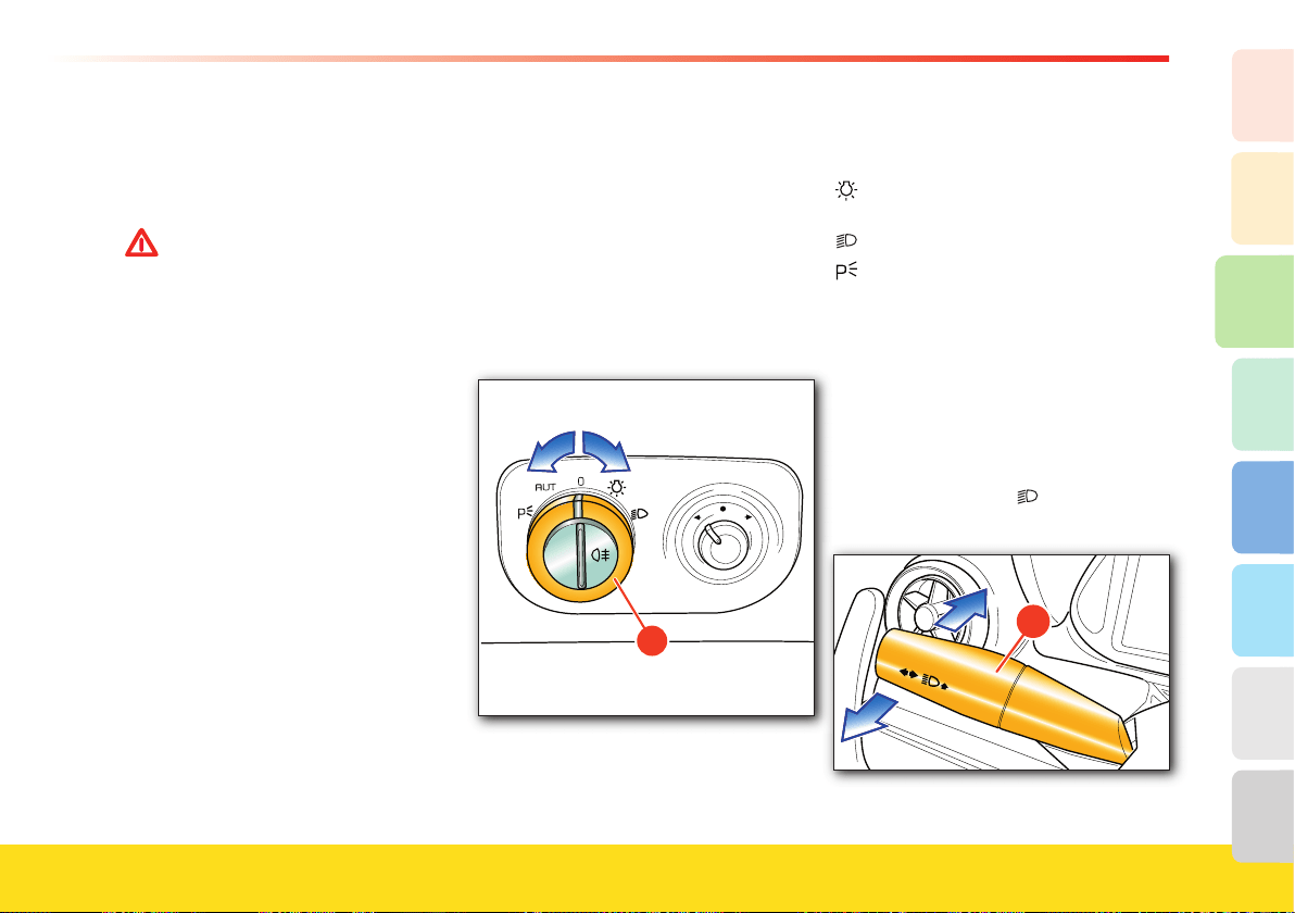
73
About your vehicle
2
1
3
8
7
6
5
4
When the door is open, the window can
only rise to the “preset position”, to prevent
the window from damaging the upper
weather strip when the door is closed.
WARNINGWARNING
Improper use of the power windows
can be dangerous. Before use, always
check that people and objects are at a
safe distance.
Pay particular attention during the
automatic operation of the driver-
side power window.
To protect the passengers remaining
in the car against accidental
operation of the power windows,
always remove the key from the
ignition.
Lighting
The external lights and the direction
indicators only work when the ignition
key is in position II
.
The external lights can be turned on and
off manually or automatically, depending
on the ambient light.
Light switch
�
Switch A has fi ve positions:
0 Lights off
Position and license plate lights
on (*)
Low beams on (*)
Parking lights on
AUT Automatic operation of the external
lights according to the ambient
light.
(*) The relative warning light on the
instrument panel illuminates (see page 93).
High beams
To turn on the high beams, when
switch A is in position , push the left-
hand lever B towards the dashboard.
B
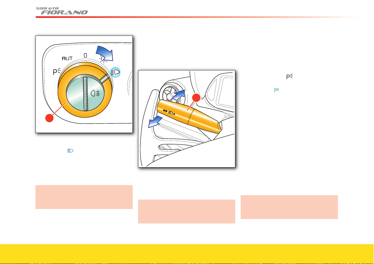
74
�
When the high beams are on, the relative
warning light
illuminates on the
instrument panel (see page 93).
Pull the lever
B towards the steering
wheel again to turn off the high beams
and turn on the low beams.
Follow the Road Regulations of the
country you are traveling in for using
the high beams.
Flashing the headlights
The headlights can be fl ashed by pulling
the left-hand lever
B towards the steering
wheel.
B
Flashing occurs also with lights off, if the
ignition key is in position II.
The high beams are used for fl ashing.
Follow the Road Regulations of the
country you are traveling in for using
the high beams.
Parking lights
The parking lights work only with the
ignition key in position
0 or with the key
removed.
They are activated by turning the light
switch
A to position .
When the parking lights are on, the relative
warning light
illuminates on the
instrument panel.
When the parking lights are on, move the
left-hand lever B downward to turn on the
left-hand position lights. Move the lever
upward to turn on the right-hand position
lights.
Automatic activation and
deactivation
When the light switch A is turned to AUT
and the ignition key is in position II, the
position lights, low beams and license plate
lights turn on and off according to the
ambient light.
The high beams can only be activated
manually, by pushing the left-hand
lever B toward the dashboard.
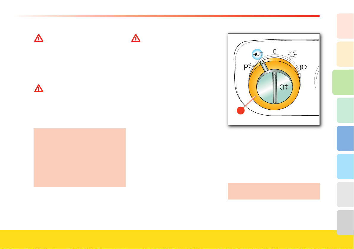
75
About your vehicle
2
1
3
8
7
6
5
4
WARNINGWARNING
If the high beam control is on, the
high beams will turn on every time
the external lights are activated
automatically. We recommend
therefore that you turn them off
every time the twilight sensor
deactivates the external lights.
WARNINGWARNING
In case of fog during the day, the
position lights and low beams will
not activate automatically. The driver
must always be ready to turn on the
lights manually, and also the rear fog
lights if necessary.
After automatic activation of the external
lights, it will always be possible to turn on
the rear fog lights manually. When the
external lights are deactivated
automatically, also the rear fog lights are
turned off (if active) automatically.
Therefore, if necessary, the user will have
to turn on the rear fog lights manually
upon the next automatic activation.
WARNINGWARNING
The driver is always responsible for
turning on the external lights,
depending on the ambient light and
in compliance with the regulations in
force in the country of use. The
automatic system for turning on and
off the external lights must be
considered an aid for the driver. If
necessary, turn the lights on and off
manually.
Twilight sensor
The twilight sensor is comprised of a
global sensor, which measures the
ambient light.
When the sensor is faulty, the system will
turn on the low beams and the position
lights regardless of the ambient light. The
failure indication will appear on the
instrument panel display.
�
The failure indication will be displayed as
long as the lights switch A is turned to
AUT.
In this case, we recommend that you
deactivate the automatic system and turn
on the external lights manually if
necessary.
Contact your Authorized Ferrari
Dealer as soon as possible.
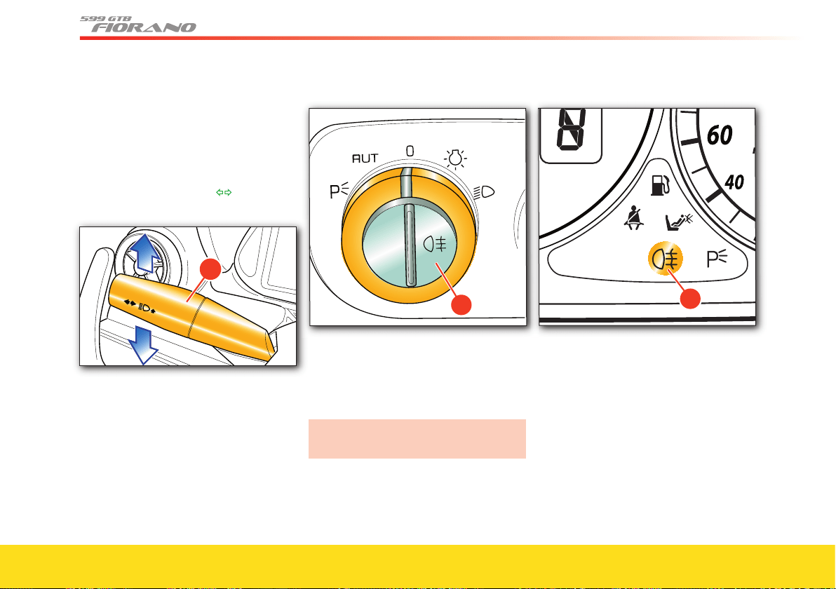
76
Direction indicators
When lever B is:
- moved up, the right-hand direction
indicators are activated
- moved down, the left-hand direction
indicators are activated.
The relative warning light will
illuminate on the instrument panel.
B
The lever returns to the neutral position
automatically when the steering wheel is
straightened.
To indicate a temporary lane change,
requiring only the slightest turn of the
steering wheel, it is possible to shift the
lever without clicking it into position
(non-permanent position).
Rear fog lights
�
These can be activated only when the high
or low beams are on, by pressing button D.
The relative warning light E on the
instrument panel will illuminate.
Use the rear fog lights only in poor
visibility conditions.
E
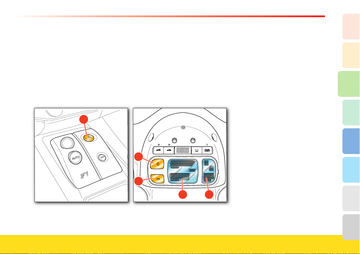
77
About your vehicle
2
1
3
8
7
6
5
4
Hazard warning lights
Press button A to turn on the hazard
warning lights. All the direction indicators
will start blinking intermittently. These
lights will operate with the ignition key in
any position.
When the lights are on, the relative
warning lights on the instrument panel
and the button will fl ash.
To turn them off, press the button again.
R
A
Dome light
When the doors are closed, the dome
light A on the roof can be turned on or
off using the switch B.
Switch
C turns on the spot light D.
The dome light activates automatically in
the following conditions:
- when a door is opened, for approx.
3 minutes
- when all the doors are closed and the
key is in position
0, for approx. 10
seconds
- when the key is removed, for approx.
10 seconds
- when the doors are unlocked, for
approx. 10 seconds
- when the inertia switch is activated, for
approx. 15 minutes.
The dome light deactivates automatically
in the following conditions:
- after the preset activation time expires
- when the doors are closed and the key is
in position II
- when the doors are locked
- when the inertia switch is reactivated.

78
Instruments and gauges
0
20
40
60
80
100
120
140
160
180
200
220
�
Instruments and gauges
1 TFT Display
2 Electronic speedometer
3 Tachometer
4 Gear display
5 Warning lights
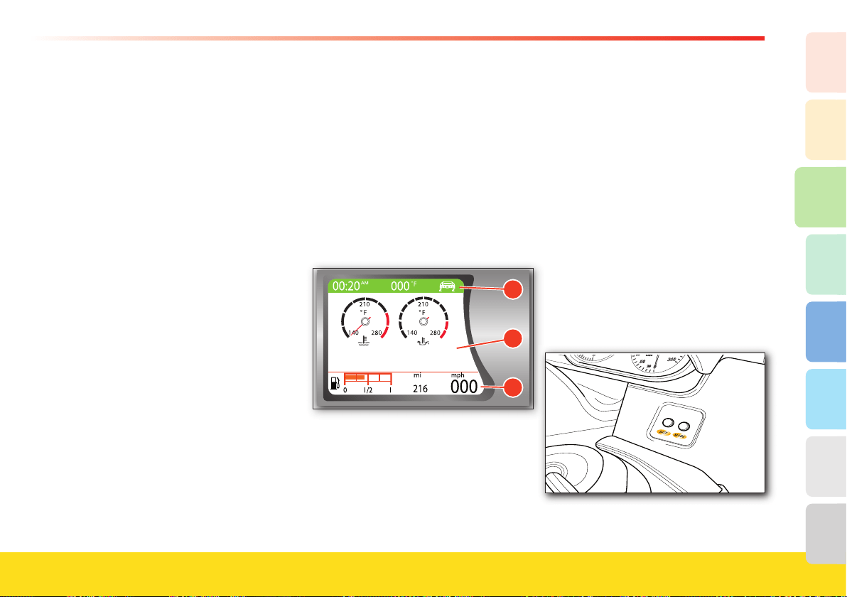
79
About your vehicle
2
1
3
8
7
6
5
4
“TFT” display
Located on the instrument panel, it
performs the following functions:
- indication of the control parameters
- indication of general information while
driving
- fault warnings.
The driver can interact with the system by
choosing graphic confi gurations and
setting the parameters.
Three different screen areas are available,
depending upon the display type chosen:
A display of information shared by all
confi gurations (with the exception of
the driving mode symbol)
B display of virtual control gauges and of
information generated by specifi c
events and/or on request
C permanent display of information
(shared by all confi gurations).
The screen areas
A and C are always
present in all display confi gurations set by
the driver.
The screen areas B and C can be
displayed with two color options:
- day (white background)
- night (black background).
The screen area
A can be displayed with
fi ve different color options, based on the
driving modes set through the
“Manettino”.
A
B
C
The screen page is activated and set by
pressing the buttons DISP and MODE on
the control panel, to the right of the
steering wheel, and by pressing the
buttons UP, DOWN and ENTER located
behind the steering wheel.
MODE
Button pressed momentarily (< 2 sec):
- the “complete” MENU page is displayed
if the vehicle speed is below 3 mph –
5 km/h
- the “minimized” MENU
page is
displayed if the vehicle speed exceeds
3 mph – 5 km/h
- within a submenu: back to last page
displayed
- odometer fl ashing: back to previous
information
- exits the display of the various check
phases when the key is turned to ON
- the malfunctions are iconized if the
button is pressed during fault warnings.

80
Button pressed at length (> 2 sec):
- MENU page not active and TRIP B
disabled: resets TRIP A
- MENU page not active and TRIP B
enabled: selects the odometer displayed
(fl ashing) (either
tot, A or B)
- MENU page active: back to last page
displayed before MODE
button was
pressed.
DISP (DISPLAY)
Scrolls through the following screen
pages:
- SPORT
- RACE
- TRIP A
- TRIP B
- TIRES
UP/DOWN
- Sets/adjusts the functions in the MENU
page
- MENU page not active: adjusts the
instrument panel brightness level
- odometer fl ashing: selects the TRIP to
reset
- Auto function (twilight sensor active):
adjusts the sensor’s sensing range.
ENTER
- MENU page not active: switches
between the information displayed:
- total odometer
- TRIP A
- TRIP B (if enabled)
- confi rms the selected function
- confi rms the setting/change
- stores the changes confi rmed
- TRIP A is reset, when TRIP B is
enabled, only after pressing the MODE
button at length (TRIP A fl ashes).
Confi gurations:
The display
B can have the following
confi gurations, which are selected using
the DISP button (the screen page recalled
is active for ten seconds), or from the
MENU
page, using the MODE button
(the screen page recalled remains
displayed as the main screen page):
- SPORT
- RACE
- TRIP A
- TRIP B
- TIRES
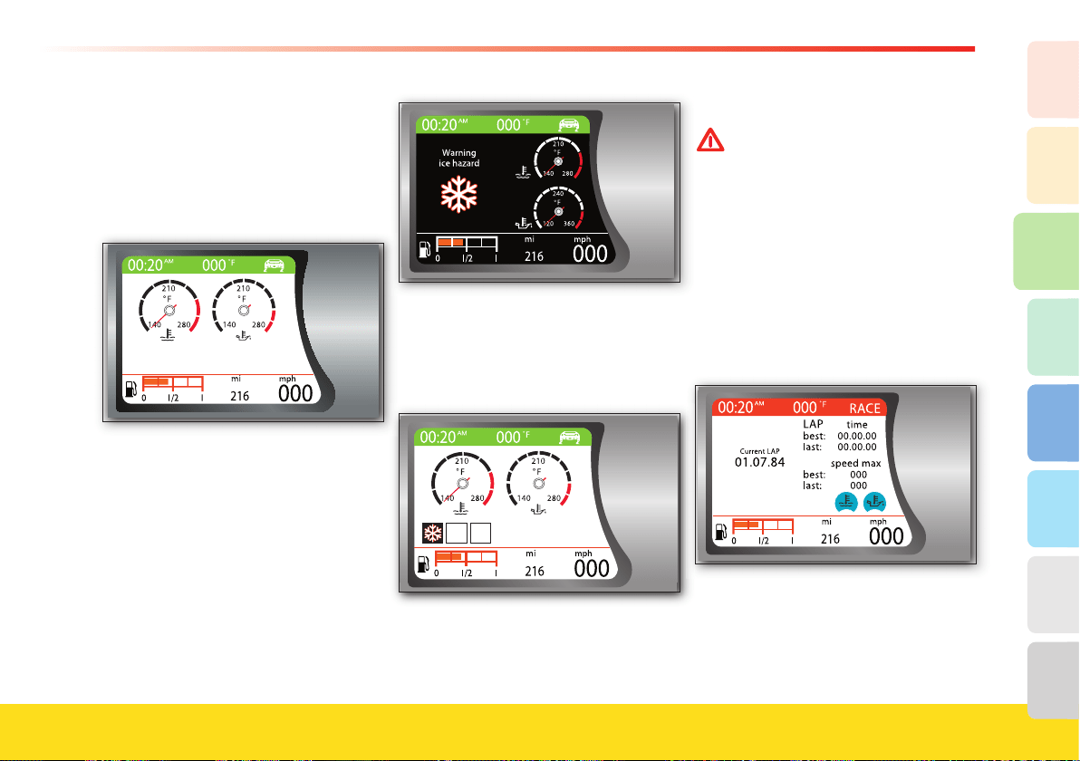
81
About your vehicle
2
1
3
8
7
6
5
4
SPORT screen page
In addition to the shared parameters, the
screen page shows the virtual control
gauges, for:
- water temperature
- oil temperature.
When the SPORT screen page is
displayed and an event occurs that needs
to be viewed, the display will appear as in
the following example.
In case of malfunctions/events which
need to be displayed through a multi-
function symbol, this will be viewed, at
the end of the display cycle, in one of the
three dedicated sections of area
B.
RACE screen page
WARNINGWARNING
RACE mode must be used only on
race tracks.
In addition to the shared parameters, the
screen page shows:
- the virtual water and oil temperature
gauges (minimized)
- Current Lap
- Best Lap
- Last Lap
- Max-Speed Best
- Max-Speed Last.
When the virtual control gauges are mini-
mized, they are displayed as symbols.
They only use black symbols on a back-
ground which can have different colors
(i.e., blue, green, red) according to the
temperature range.
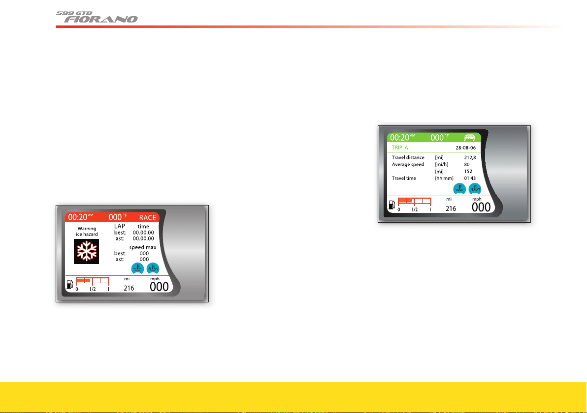
82
Oil temperature gauge:
- Blue = < 131 °F (55 °C)
- Green = 131 °F (55 °C)
- 311 °F (155 °C)
- Red =
> 311 °F (155 °C).
Water temperature gauge:
- Blue =
< 158 °F (70 °C)
- Green = 158 °F (70 °C)
- 257 °F (125 °C)
- Red =
> 257 °F (125 °C).
When the RACE screen page is displayed
and an event occurs that needs to be
viewed, the display will appear as in the
following example.
During display of the event/malfunction ,
the chronometer remains active and is
viewed again at the end of the display
cycle. In the event of priority level
0
malfunctions (see “TFT display warning
lights”) the chronometer is deactivated.
When the RACE screen page is displayed,
the functions of some buttons change.
The ENTER
button is used to start the
chronometer:
- when the chronometer is off, press the
button to activate the Current Lap
chronometer
- when the chronometer is on, press the
button to reset and restart the Current
Lap and update the information about
the previous laps.
The DISP
button:
- stops the chronometer and updates the
information on the previous laps (button
pressed briefl y)
- resets the chronometer and updates the
information about the previous laps
(button pressed briefl y).
The RACE screen page cannot be
selected from the MENU
page when the
following driving modes are active:
SPORT, LOW GRIP and ICE.
TRIP A and B screen page
In addition to the shared parameters, the
screen page shows:
- the virtual water and oil temperature
gauges (minimized)
- the date
- the trip distance
- the average speed
- the cruising range
- the trip time.
If the driver selects TRIP B as main
screen page and then deselects TRIP B
from the Menu page, the default screen
page will be automatically set as main
page.
When the TRIP A
or B screen page is dis-
played and an event occurs that needs to
be viewed, the display will appear as in
the following example.
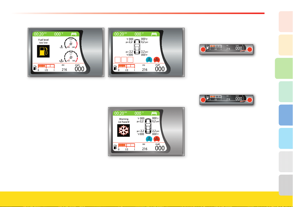
83
About your vehicle
2
1
3
8
7
6
5
4
In case of malfunctions/events which
need to be displayed through a multi-
function symbol, they will be viewed, at
the end of the display cycle, in one of the
three dedicated sections of area
B.
TIRES screen page
In addition to the shared parameters, the
screen page shows:
- the virtual water and oil temperature
gauges (minimized)
- the vehicle symbol with the pressure
and temperature values for each tire
- the multi-function symbol for
malfunctions (if any).
When the TIRES screen page is displayed
and an event occurs that needs to be
viewed, the display will appear as in the
following example.
For further information, please see the
“Tire Pressure and Temperature
Monitoring System” in the “Safety”
section.
Parameters shared by all
confi gurations:
C
1
Odometer
The odometer is always viewed on the
TFT display (in area C: by pressing the
ENTER button, the user can select
whether to view the total odometer 1 or
one of the two trip odometers
2.
�
To reset the trip odometers, press and
hold the MODE button. If TRIP B is not
enabled, TRIP A is automatically reset,
whereas if it is enabled, the active
odometer fl ashes. Use the UP
and DOWN
buttons to select the desired TRIP, and
press ENTER to reset the fl ashing
odometer.
When the odometer is fl ashing, to return
to the previous screen page press the
MODE
button momentarily or wait 10
seconds.

84
Fuel level gauge
The information is permanently displayed
in area C.
Speedometer
The information is displayed in area
C.
If the speedometer display is disabled, the
outside temperature will be viewed in its
place.
Clock
A
The clock is always displayed in area A, in
all confi gurations, and can be viewed in
the “24h” or “12h – AM/PM” format.
Outside temperature gauge
The information is displayed in area A, if
the speedometer display (area C) is
enabled.
The information is displayed in area
C, if
the speedometer display is disabled. In
this case, the word “Manettino” will be
displayed in area
A.
Driving mode symbol
The information is permanently displayed
in area A.
Confi guration settings:
Menu Page
To display the MENU page, press the
MODE button momentarily.
The parameters that may be set are:
- Brightness
- Display setting
- Date and time
- Language and units of measurement
- Vehicle setting
- Service.
To select the above mentioned parameters
and the related functions, use the UP and
DOWN
buttons.
To confi rm the selected parameter, press
ENTER
.
Lighting
The day-time or night-time mode are set
depending upon activation of the position
lights. However, if the twilight sensor
detects suffi cient light, it may not switch
to the night-time mode. Both options have
eight brightness levels which can be set
using the UP and DOWN buttons. To
confi rm the selected parameter, press
ENTER
.
To adjust the brightness level, you can use
the UP and DOWN buttons without
accessing the MENU page.
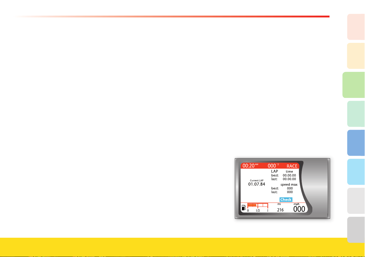
85
About your vehicle
2
1
3
8
7
6
5
4
Display setting
In this area the user can choose the
confi guration that will be permanently
displayed. The following options are
available: SPORT, RACE, TIRES, TRIP
A and TRIP B. The RACE screen page is
not available when the “Manettino” is set
to SPORT, LOW GRIP or ICE.
Date and time
The date may be displayed in two
formats: day/month/year or month/day/
year. Press the UP
and DOWN buttons to
select the desired format and adjust the
date. Press ENTER to confi rm.
The time may be displayed in the “24h”
or “12h – AM/PM” format. To select
the format and adjust it, use the UP and
DOWN buttons and confi rm with
ENTER
.
Language and units of measurement
The language options available are:
- English
- German
- Italian
- French
- Spanish.
The units of measurement options are:
- distance (km or miles)
- temperature (°C or °F)
- pressure (bar or psi).
To select the parameters, press the UP
and DOWN buttons. To confi rm the
selected parameter, press ENTER
.
Vehicle setting
The parameters that can be changed are:
- Park. sensor*
- Door locking
- Door unlocking
- Speed limit buzzer
- Buzzer volume
- Light sensor
- Glove compartment button
- RPM rep. on the steering wheel
- Equalizer.
* if the vehicle is equipped with optional
parking sensors
To select the parameters, press the UP
and DOWN buttons. To confi rm the
selected parameter, press ENTER
.
Service
Select
Service to view the
MAINTENANCE SCHEDULE (see
“Warranty and Service Book”).
Displayed information upon key-on
When the key is turned to ON, the check
procedure is started and the word
“Check” will be displayed in area B, on a
pale blue background. The main screen
pages that normally display the virtual
water and oil temperature gauges
(minimized) will not be viewed during
the check stage.
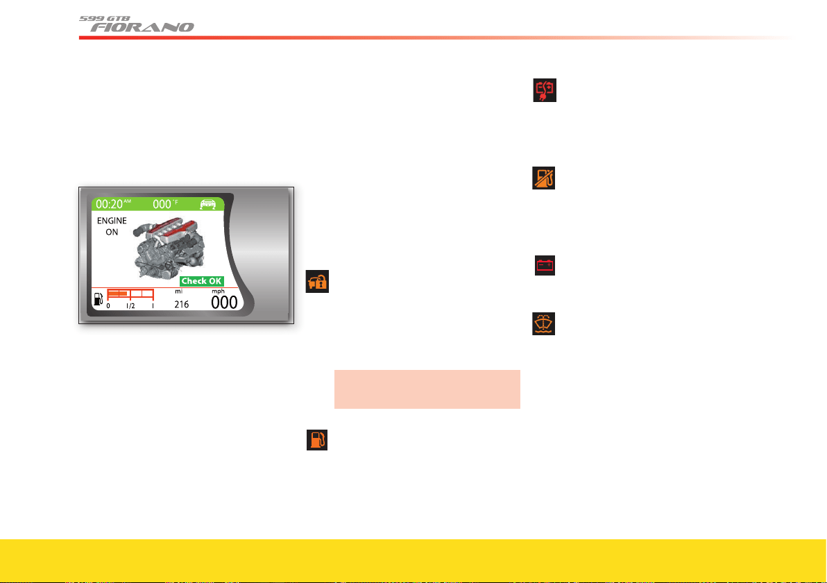
86
Once the check procedure is successfully
completed, the word “Check” will be
replaced by “Check OK
” on a green
background.
When the engine is started, regardless of
the main screen page set, the words
“ENGINE ON” will be displayed.
TFT display warning lights
Priority level 0 (Extremely critical
malfunction): remains displayed for an
unlimited period of time, until the
problem is corrected.
Priority level 1
/Priority level 2 (Critical
malfunction/Non-critical malfunction):
remains displayed for 20 seconds in the
center of area B and is then minimized. It
remains displayed (minimized) at the
bottom left of area B, until the problem
is corrected.
Alarm system failure
Indicates a fault in the alarm system
(priority level 1).
The system is not programmed
(priority level 2).
It may be associated with messages.
Contact your Authorized Ferrari
Dealer.
Fuel reserve
Indicates that the fuel level is low
(priority level 2).
Battery conditioner connected
When the instrument panel is on, it
indicates that the connection with
the battery conditioner is active
(priority level 0).
Inertia switch
Indicates activation of the inertia
switch following an accident and the
resulting cut-off of the fuel supply
(priority level 0).
Alternator
Indicates an alternator failure
(priority level 1).
Low windshield washer fl uid level
Indicates a low level of washer fl uid
in the windshield washer tank
(priority level 2).
87
About your vehicle
2
1
3
8
7
6
5
4
Oil temperature
Indicates that the oil temperature is
too high (priority level 0).
Turn off the engine and contact
your Authorized Ferrari Dealer.
Oil pressure
Indicates that the oil pressure is too
low (priority level
0).
Turn off the engine and contact
your Authorized Ferrari Dealer.
Engine coolant temperature
Indicates that the engine coolant
temperature is too high (priority
level 0).
Turn off the engine and contact
your Authorized Ferrari Dealer.
On-board diagnostic system (OBD)
Indicates a malfunction or failure of
the Ignition/Injection System
and/or the Emission Control System
(priority level 0).
Generic failure
Indicates a generic failure (priority
level 0). A failure message is
associated with the warning light.
Lights failure
Indicates a system failure or
burning-out of the light bulbs in the
position, direction indicators or rear
fog lights (priority level 2).
Number plate lights failure
Indicates a system failure or
burning-out of the license plate light
bulb (priority level 2).
Twilight sensor failure
Indicates a twilight sensor failure
(priority level 2).
Stop lights failure
Indicates a system failure or
burning-out of the STOP light bulb
(priority level 2).
Seat heating
Indicates that the seat heating
function is active (front RH/LH).
(Remains displayed for 5 seconds)
88
Catalytic converter temperature
If flashing, it indicates that the
catalytic converter temperature is
too high: slow down until the
warning light goes off (priority level
1). A failure message is associated
with the warning light.
If the warning light remains on
without flashing, the catalytic
converter temperature is excessively
high; stop the vehicle (priority level
0) and turn off the engine so the
exhaust system can cool down (see
pag. 156). After about five minutes,
start the engine again and drive
normally. A failure message is
associated with the warning light.
Indicates a failure of the catalytic
converter temperature sensor
(priority level 0). A failure message
is associated with the warning light.
Power steering failure
Indicates that the power steering
system is inefficient (priority
level 2).
Contact your Authorized Ferrari
Dealer.
Fuel tank door open
Indicates that the fuel tank door is
open (acoustic signal when the
vehicle is moving).
Low F1 gearbox oil level
The red symbol indicates that the
F1 gearbox oil level is too low
(priority level 0).
Contact your Authorized Ferrari
Dealer.
Doors or front/rear lids open
Indicates that the doors or front/
rear lids are open or improperly
closed. The part concerned is
highlighted in red (acoustic signal
when the vehicle is moving).
ABS
Indicates an ABS system failure
(priority level 1).
The standard braking system is
still functioning.
Contact your Authorized Ferrari
Dealer.
EBD
Indicates an EBD system failure.
(priority level 0).
It is displayed together with the
ABS warning light.
WARNINGWARNING
Stop the vehicle avoiding hard
braking. Drive at low speed
(max. 25 mph - 40 km/h) to
leave the road. Do not drive
further and contact an
Authorized Ferrari Dealer
immediately.
ASR + CST on
Indicates that the ASR and CST
systems are active (priority level 1).
A failure message is associated with
the warning light.
89
About your vehicle
2
1
3
8
7
6
5
4
ASR + CST off
Indicates that the ASR and CST
systems are deactivated (priority
level 1). This is displayed together
with the words CST off.
A failure message is associated with
the warning light.
ASR/CST failure
Indicates an ASR/CST system
failure (priority level 1).
A failure message is associated with
the warning light.
WARNINGWARNING
Stop the vehicle avoiding hard
braking. Drive at low speed
(max. 25 mph - 40 km/h) to
leave the road. Do not drive
further and contact an
Authorized Ferrari Dealer
immediately.
CCM brake discs worn
Indicates that the carbon ceramic
discs are worn (priority level 2).
Contact your Authorized Ferrari
Dealer to have the brake pads
replaced.
ASR/CST system activation
Indicates that the CST system has
activated (priority level 1).
A failure message is associated with
the warning light.
Tire pressure
Warning light connected with the
tire pressure monitoring system
(priority level 0 or 2).
Airbag system failure
Indicates a system failure (priority
level 0). At the same time, the
Airbag warning light remains on.
Contact your Authorized Ferrari
Dealer.
Indicates that the Airbag test cycle
has not been completed. At the
same time, the Airbag warning light
flashes (priority level 0).
Speed limit exceeded (km/h)
Indicates that the speed limit set by
the user has been exceeded (priority
level 2).
Driver-side seat belt not fastened
Indicates that the driver-side seat
belt is not fastened
(priority level 0).
Brake malfunction
Indicates that the brake fluid is low
or that there is an EBD failure
(priority level 0).
Rain sensor failure
Indicates a rain sensor failure
(priority level 2).
Suspension control system failure
Indicates a malfunction in the
suspension control system (priority
level 2).
Contact your Authorized Ferrari
Dealer.
"Manettino" failure
Indicates a "Manettino" failure
(priority level 1). A failure message
is associated with the warning light.
Parking sensor failure
Indicates that the parking sensor
system is faulty (for vehicles
equipped with this system) (priority
level 2).
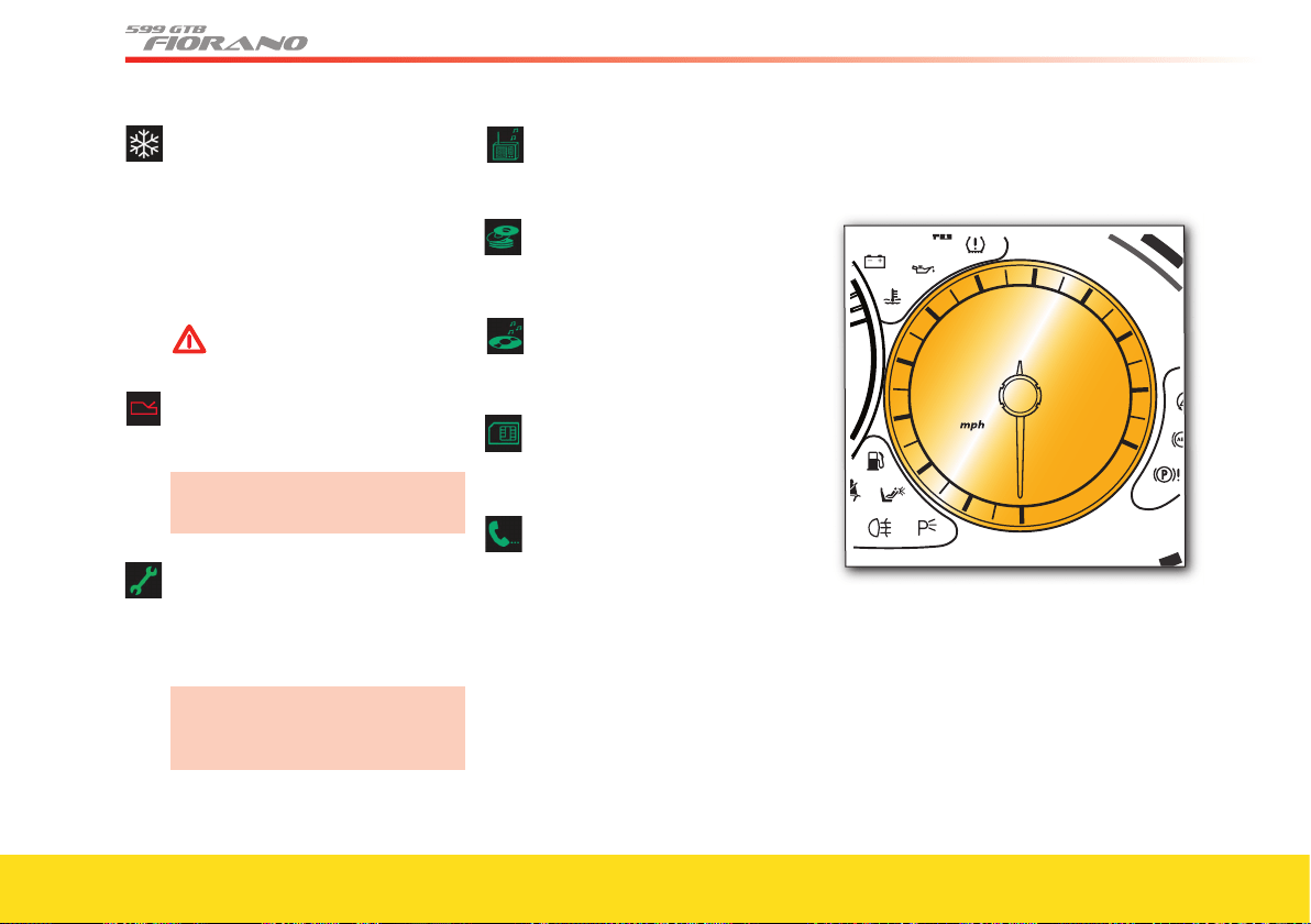
90
Ice hazard
Indicates that the outside
temperature is 38 °F (3 °C) or lower,
indicating the risk of icy road
surfaces.
Drive carefully and slow down as
the grip of the tires could be
markedly reduced.
WARNINGWARNING
In this condition, do not
activate “SPORT” or "RACE"
mode.
F1 gearbox failure
Indicates an F1 system failure
(priority level 1).
Contact your Authorized Ferrari
Dealer.
Scheduled maintenance
Depending on the associated
message, this indicates that service
schedule deadlines are either
approaching or due.
Contact your Authorized Ferrari
Dealer upon reaching this
deadline.
Radio system information
See the “Quick reference” guide for
the car radio system.
CD-Changer information
See the “Quick reference” guide for
the car radio system.
CD, MP3 CD information
See the “Quick reference” guide for
the car radio system.
Flashcard information
See the “Quick reference” guide for
the car radio system.
Telephone
See the “Quick reference” guide for
the car radio system.
Electronic speedometer
Indicates the vehicle speed.
If the external temperature is not
displayed, the speed will also be shown
on the TFT display.
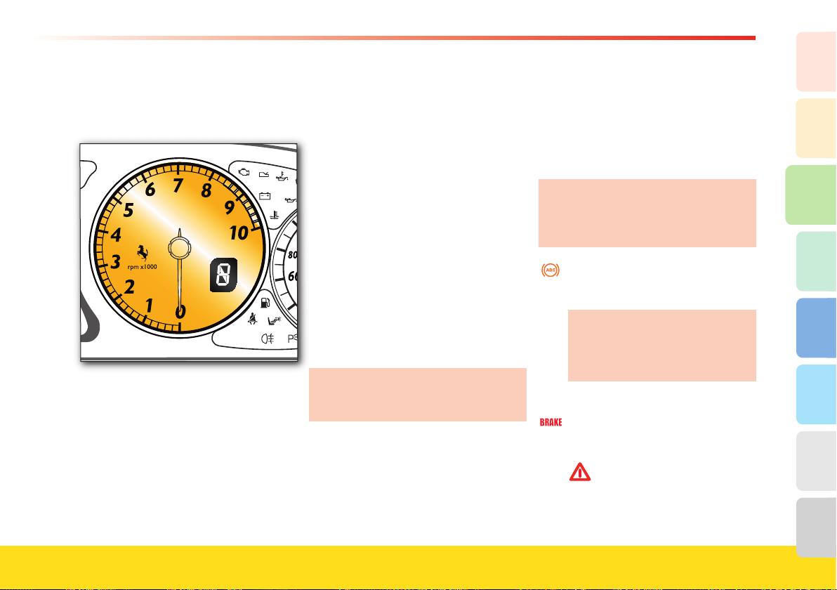
91
About your vehicle
2
1
3
8
7
6
5
4
Tachometer
Indicates the engine RPM. Avoid engine
speeds in the red sector.
If such speed rates are exceeded, the
ignition/injection ECU will temporarily
cut-off the fuel supply.
Gear display (F1)
It is incorporated in the tachometer. With
the ignition key in position
II, it displays
the gear engaged.
N Neutral
R Reverse
1 1st gear
2 2nd gear
3 3rd gear
4 4th gear
5 5th gear
6 6th gear
Auto Automatic gearshift mode
Auto
▼
Easy exit mode
When the symbol “_” is displayed, it
indicates a fault in the gearbox.
Please contact your Authorized
Ferrari Dealer to have the necessary
checks performed.
Warning lights
In addition to the self-check performed
before ignition, the warning lights may
illuminate in the following cases:
(x) associated with a specifi c TFT display
warning light
If a warning light indicating a failure
illuminates while driving, contact your
Authorized Ferrari Dealer to have the
necessary checks performed.
ABS (x)
While driving, it illuminates to
indicate a failure in the ABS system.
The standard braking system is
still functioning.
Contact your Authorized Ferrari
Dealer.
Brake failure (x)
Indicates that the brake fl uid level
in the tank is too low.
WARNINGWARNING
Stop the vehicle avoiding hard
braking. Do not drive further,
check the fl uid level in the tank
and immediately contact your
Authorized Ferrari Dealer.
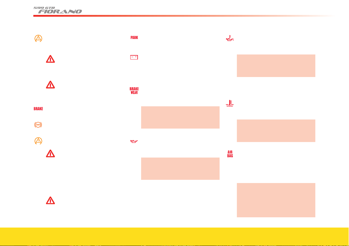
92
ASR/CST failure (x)
Indicates an ASR/CST system
failure.
WARNINGWARNING
Stop the vehicle avoiding hard
braking. Do not drive further
and immediately contact your
Authorized Ferrari Dealer.
WARNINGWARNING
The vehicle can still be driven
at low speed (max. 25 mph –
40 km/h), to leave the road.
Failure of all the braking systems “ABS –
EBD – CST” (x)
When the three warning lights
illuminate simultaneously.
WARNINGWARNING
Danger of rear wheels locking
and risk of spinning.
Stop the vehicle avoiding hard
braking. Do not drive further
and immediately contact your
Authorized Ferrari Dealer
.
WARNINGWARNING
The vehicle can still be driven
at low speed (max. 25 mph –
40 km/h), to leave the road.
Parking brake
When the handbrake is applied.
Alternator failure (x)
If the charging system is faulty.
When the battery is insufficiently
charged or overcharged (flashing).
Brake pad wear (x)
Indicates that the brake pads are
worn.
Contact your Authorized Ferrari
Dealer to have the brake pads
replaced.
Oil pressure (x)
Indicates that the engine oil
pressure is too low.
Turn off the engine immediately
and contact your Authorized
Ferrari Dealer.
Indicates that the specific sensor is
faulty.
Oil temperature (x)
Indicates that the engine oil
temperature is too high.
Turn off the engine immediately
and contact your Authorized
Ferrari Dealer.
Indicates that the specific sensor is
faulty.
Engine coolant temperature (x)
Indicates that the engine coolant
temperature is too high.
Turn off the engine immediately
and contact your Authorized
Ferrari Dealer.
Airbag system failure (x)
While d
riving, it indicates a
malfunction in the airbag system
and/or in the seat belt
pretensioners.
If the warning light does not
illuminate for the self-check cycle
or if it illuminates on while
driving, contact your Authorized
Ferrari Dealer immediately.
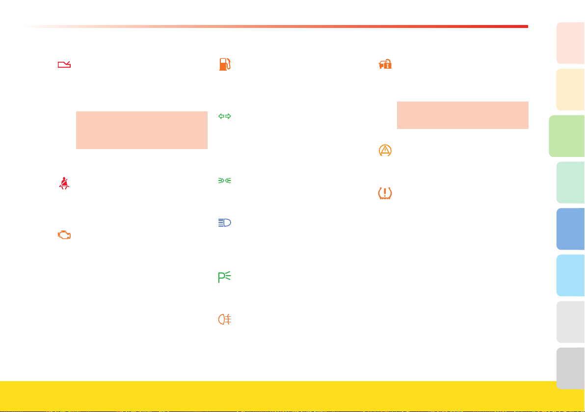
93
About your vehicle
2
1
3
8
7
6
5
4
F1 gearbox failure (x)
- Warning light permanently on
accompanied by an acoustic alarm:
when an operating error occurs in
the F1 gearbox.
If the failure still permits it, leave
the road and contact your
Authorized Ferrari Dealer.
- Flashing: low system pressure.
Seat belt (x)
When the ignition key is in
position II, it indicates that the
driver’s seat belt is not fastened.
On-board diagnostic system (OBD) (x)
It indicates a malfunction in the
emission control system and/or
ignition/injection system.
After turning the ignition key to
position II, this remains on for a self
check for
eighteen seconds
following engine starting.
Fuel reserve (x)
Indicates that only 20 liters of fuel
are left in the tank or that the level
gauge is malfunctioning.
Direction indicator
When the direction indicators are
activated.
When the hazard lights are turned
on.
Position lights
When the position lights or low
beams are turned on.
High beams
When the high beams are turned on.
When the high beams are used to
flash.
Parking lights
When the parking light control
button is pressed.
Rear fog lights
When the rear fog lights are turned
on.
Alarm system failure (x)
While driving, it illuminates to
indicate a failure in the alarm
system.
Contact your Authorized Ferrari
Dealer.
ASR + CST off (x)
Indicates that the ASR and CST
systems are deactivated.
Tire pressure and temperature monitoring
system
Warning light connected with the tire
pressure and temperature monitoring
system (on page 56)
.

94
Roof panel controls
Deactivating the alarm system
motion sensors
Pressing button A deactivates the motion
sensing feature of the alarm system.
When this feature is deactivated, the LED
above the button fl ashes for about 3
seconds and then turns off.
Deactivating the anti-lift alarm
system
Pressing button B deactivates the anti-lift
alarm system.
When this feature is deactivated, the LED
above the button fl ashes for about 3
seconds and then turns off.
Tire pressure calibration button
To calibrate the system, when the key is
in position II, press button C until the
message “calibration activated” appears on
the TFT display.
The system will take a maximum of
20 minutes to complete the calibration
procedure with the vehicle in motion.
For further information, please see the
“Tire pressure and temperature
monitoring system” (on page 55).
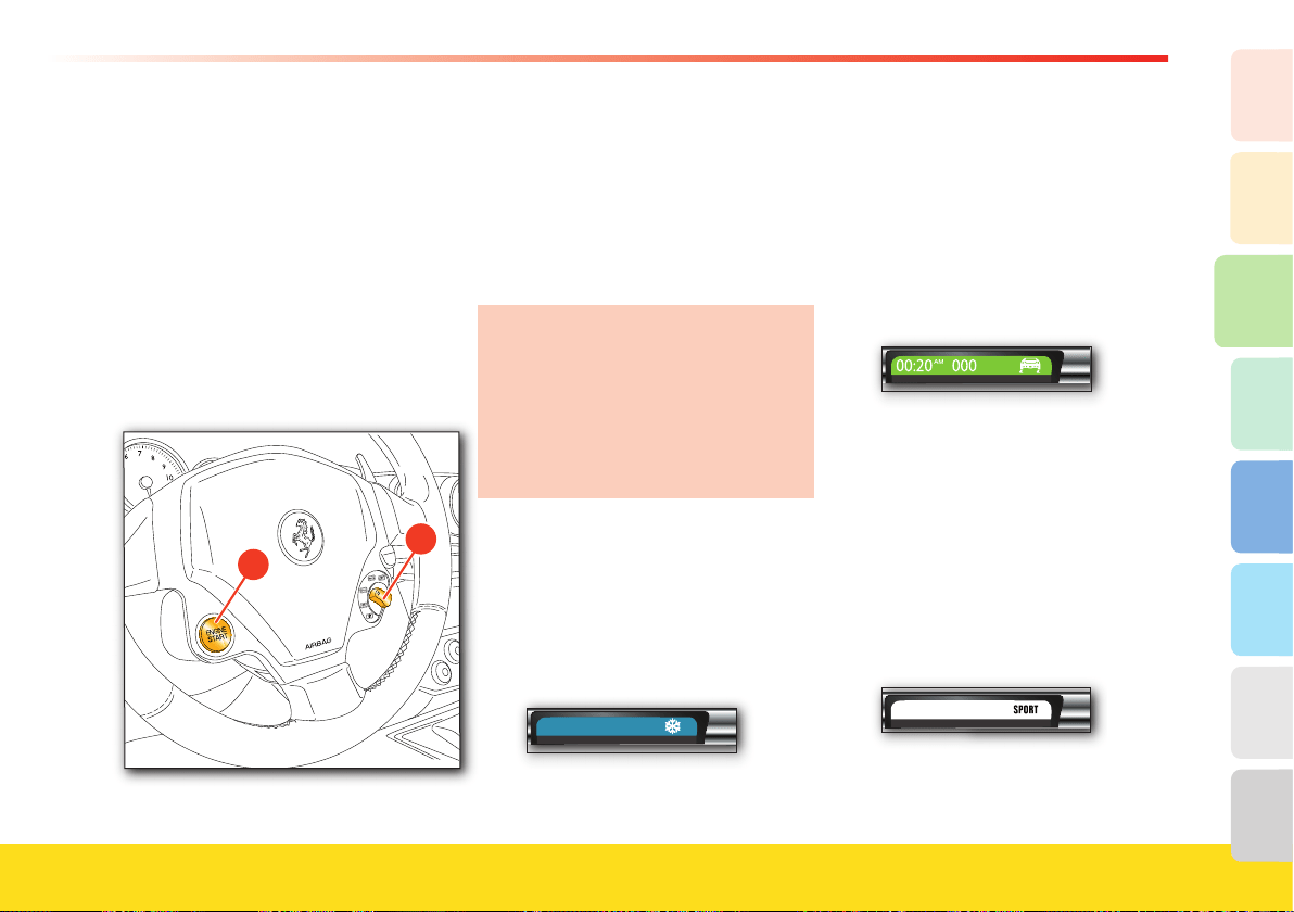
95
About your vehicle
2
1
3
8
7
6
5
4
Controls on the steering wheel
Start button
Press the ENGINE START button A to
start the engine. When the engine has
started, release the ENGINE START
button.
Do not hold the ENGINE START button
down for a long time.
For the starting procedure, see “Starting
and driving the vehicle” on page 100.
Driving mode selection switch
The driving mode selected does not
exempt the driver from complying with
the rules of safe driving.
The driver can select the driving mode
using the “Manettino” B, according to the
desired driving style.
In the event of a failure of one of the
onboard systems, indicated by the
warning light on the instrument panel
display (see page 89), the system
moves to a “recovery” mode, allowing
the vehicle to still be driven. In these
cases, contact your Authorized Ferrari
Dealer.
ICE mode
This mode can be used when the road
conditions are particularly slippery (e.g.,
snow, ice).
Activation will be indicated by the ICE
symbol in the dedicated area on the TFT
display.
00:20 000
AM
°F
For use, see on page 115.
LOW GRIP mode
This mode can be activated when driving
comfort is required, even for sports-style
driving, to help ensure stability in low and
medium grip conditions. This
mode is
recommended also for city driving.
Activation will be indicated by the Low
Grip symbol in the dedicated area of the
TFT display.
°F
For use, see on page 115.
SPORT mode
This is the ideal setting for vehicle
performance.
Select SPORT mode for sports-style
driving, under high-grip conditions.
Activation will be indicated by the
SPORT symbol in the indicated area on
the TFT display.
AM
°F
For use, see on page 115.

96
RACE mode
WARNINGWARNING
RACE mode must be used only on
race tracks.
RACE mode is designed to further
enhance the racing style performance of
the vehicle. Activation will be indicated by
the RACE symbol in the dedicated area
on the TFT display.
This mode is ideal for using the vehicle
on the race track.
°F
For use, see on page 116.
Deactivating the CST system (
CST
)
Select this mode to deactivate the CST
system (always active when the engine is
started).
00:20 000
AM
°F
Deactivation of this mode will be
indicated by the warning light
A on the
instrument panel and by the ASR/CST
failure warning light with the message
“CST off ” appearing on the TFT display
for 5 seconds.
In addition, CST deactivation will cause
the RACE and
CST
symbol to be
displayed in the dedicated area on the
TFT display.
An acoustic signal will warn the driver that
the driving mode has been changed.
When the CST feature is active, the
warning light A starts fl ashing on the
instrument panel, and the relative warning
light on the TFT display illuminates
accompanied by the message “ASR/CST
active”.
In low- to medium-grip conditions (e.g.,
wet, icy, sandy roads), do not deactivate
the CST system.
When the CST
system is active and the
amber warning light comes on, it means
that there is a fault in one of the CST
system components.
A
Contact an Authorized Ferrari Dealer.
Every time the engine is then started,
the CST system will reactivate.
The CST system reactivates
automatically, even in
CST
mode, when
the brake pedal is depressed.
When the brake pedal
is released the
VDC system deactivates.
For use, see on page 116.

97
About your vehicle
2
1
3
8
7
6
5
4
Horn control
Press the upper sides of the steering
wheel rim, in position with the horn
symbol, to activate the horn.
“UP” gearshift lever
(vehicles with F1 gearbox)
Pull the right-hand UP lever towards the
steering wheel to shift gears up.
For use, see “Starting and driving the
vehicle” (F1) on page 100.
“DOWN” gearshift lever
(vehicles with F1 gearbox)
Pull the left-hand DOWN lever towards
the steering wheel to shift gears down.
For use, see “Starting and driving the
vehicle” (F1) on page 100.
Windshield washer/wipers and
headlight washer
Windshield wipers
The windshield wipers and washer
work only with the ignition key in
position II.
The lever A has 5 settings:
OFF Windshield wipers stationary.
AUTO
Automatic operation. In this
position, the rain sensor’s sensing
range can be adjusted (lever
pushed down to fi rst click).
1 Slow continuous operation (lever
pushed down to second click.
2 Fast continuous operation (lever
pushed down to third click).
Lever Fast temporary operation
up (automatic return).
Windshield washer
This is activated by pulling lever A towards
the steering wheel (automatic return).
When the windshield washer is activated,
the windshield wiper starts automatically.
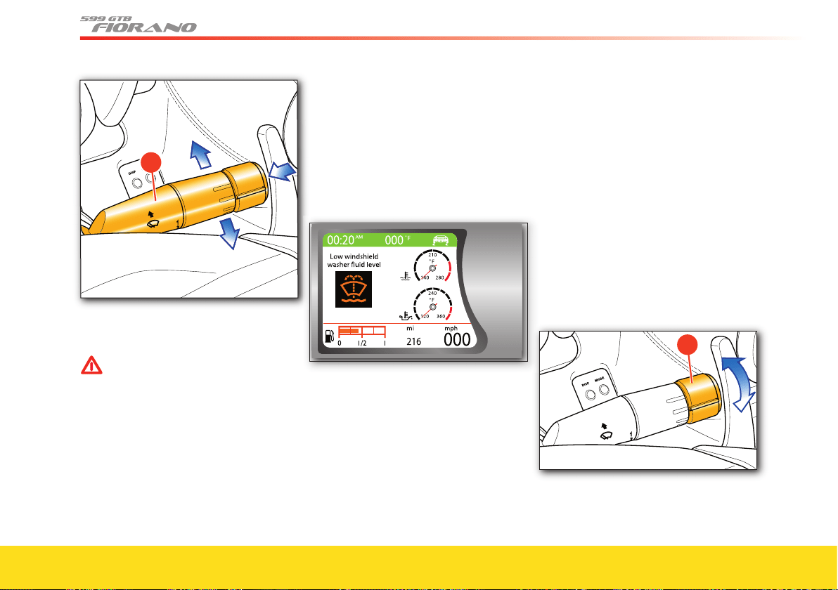
98
A
U
TO
O
FF
A
Releasing the lever stops the jet of fl uid
while the blades continue to wipe for a
short time.
WARNINGWARNING
Do not operate the windshield
washer during the cold months until
the windshield has warmed up. If it
has not warmed up, the liquid could
freeze on the glass and block the
view.
Headlight washer (optional)
The headlight washer is activated
automatically when the windshield washer
is operated and the low beams are on.
The headlight washer and windshield
washer share the same fl uid tank, and a
low fl uid level is indicated by the relative
warning light on the TFT display.
Rain sensor
The rain sensor automatically adjusts the
windshield wiper timing to the intensity
of the rain during intermittent operation.
All functions controlled by the right-hand
lever are unaffected.
The rain sensor automatically activates
when the right-hand lever is moved to
AUTO
, and it has a range of adjustment
which runs from “wiper stationary” (when
the windshield is dry) to “fast continuous
operation” (with heavy rain).
To regulate the frequency of intermittent
operation, with the lever at AUTO, turn
the control C.
A
UT
O
O
F
F
C

99
About your vehicle
2
1
3
8
7
6
5
4
Turning the control clockwise,
intermittent operation varies from a
maximum (fast intermittent operation) to
a minimum (slow intermittent operation).
The rain sensor function is reset by
turning the ignition key to position 0,
and also by leaving the right-hand
lever in position AUTO. To reactivate
it, turn the control to OFF and then
again to AUTO.
WARNINGWARNING
Before cleaning the front windshield
(for example in service stations)
make sure the rain sensor is
deactivated or that the key is at
position 0. The rain sensor must be
deactivated also when washing the
vehicle by hand or in automatic car
washes.
In case of ice or snow on the front
windshield, do not activate the rain
sensor to avoid damaging the wiper
motor and/or blades.
Rain sensor failure
In the event of a malfunction occurring
when the rain sensor is active, the wipers
will be set to intermittent operation and
the sensing range will be set by the driver,
whether there is rain on the windshield or
not. In this case, we recommend that you
deactivate the rain sensor and turn on the
wipers, if necessary, in continuous mode.
Contact your Authorized Ferrari
Dealer as soon as possible.
Driving the vehicle
Running-in
The latest manufacturing techniques have
allowed us to achieve high precision and
accuracy levels in the construction and
assembly of components. Nonetheless, the
vehicle’s moving parts need to be run-in,
especially in the first hours of driving the
vehicle.
Engine and transmission
Avoid exceeding 5000 RPM for the first
620 mi. (1000 km).
After starting, do not exceed 4000 RPM
until the engine has warmed up (oil
temperature: 149/158 °F – 65/70 °C).
Do not let the engine run at a constantly
high speed for a prolonged time.
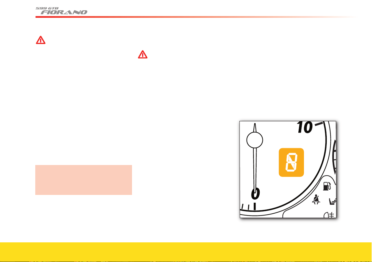
100
WARNINGWARNING
BEFORE YOU DRIVE
Check that the seat belts are fastened.
Check that the doors are closed.
Check that the seat is properly
adjusted.
Check the rear-view mirror adjustment
(center and sides).
Before a trip
Preliminary checks
Check the following at regular intervals
and always before long trips:
- tire pressure and condition
- levels of fl uids and lubricants
- condition of the windshield wiper blades
- proper functioning of the warning lights
and external lights.
In any case, it is advisable to perform
these checks at least every 620 mi.
(1000 km), and to always comply with
the maintenance schedule.
It is also advisable to:
- clean the glass covers of the external
lights and all the glass surfaces
- properly adjust the mirrors, steering
wheel, seats and seat belts.
Recommended lubricants and fl uids
WARNINGWARNING
Use unleaded fuel only!
Using leaded fuel would
permanently damage the catalytic
converters.
To help ensure optimum engine operation
and the best vehicle performance, use
“Premium Gasoline” with an octane level
of 91-94 A.K.I..
For specifi cations and quantities of lubri-
cants and fl uids, follow the information
reported in the “Recommended lubricants
and fl uids” table on page 30.
Starting and driving the vehicle
(F1 gearbox)
System starting
When the ignition key is turned to posi-
tion II the gear display and all its seg-
ments, as well as the relative failure warn-
ing light illuminate. The warning light will
turn off if no problems are detected with-
in a few seconds.
The gear currently engaged will remain
highlighted on the display.
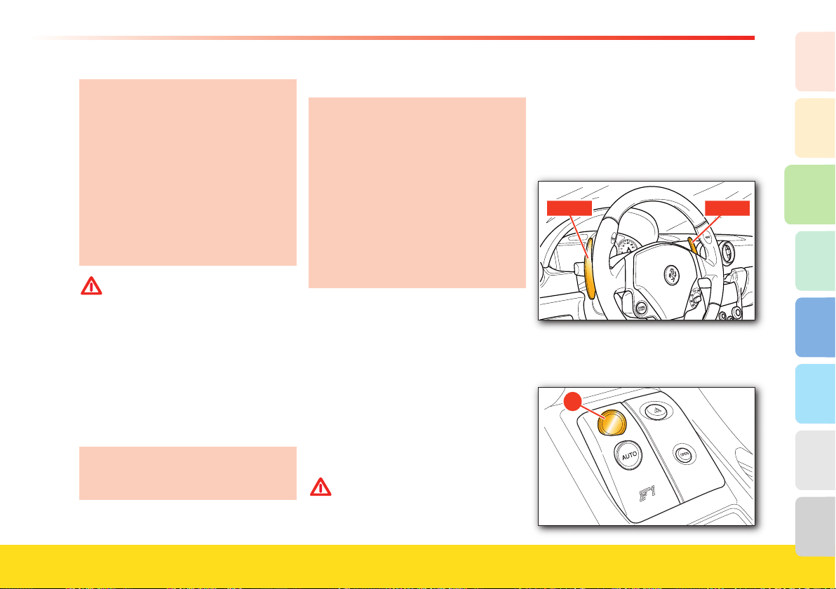
101
About your vehicle
2
1
3
8
7
6
5
4
When the driver-side door is opened,
the system pump may activate for
several seconds. This function allows
the system to be ready for operation
when the ignition key is inserted.
The failure warning light may also
fl ash for a short time (10 sec.) and
then turn off: the system completes the
“start-up” phase and will then start
functioning normally. Avoid entering
any commands in the system during
this stage.
WARNINGWARNING
If the failure warning light continues
fl ashing without going off, deactivate
the system and restart it. If the
failure persists, contact an
Authorized Ferrari Dealer
to have
the necessary checks performed.
If the warning light remains on, it means
that there is a system failure. This
condition will also be indicated by an
acoustic alarm when the ignition key is
turned to position II.
Contact your Authorized Ferrari
Dealer to have the malfunction
identifi ed and corrected.
Operation with the engine off
The default setting for the F1 gearbox
is always “AUTO” mode.
Every time the vehicle is started, the
F1 gearbox is in “AUTO easy exit”
mode, unless the gearbox was in
“AUTO” mode when the engine was
turned off (see page 106).
To exit “AUTO easy exit” mode,
operate one of the levers UP and
DOWN (when the vehicle is moving)
or
press the AUTO button on the
center console.
Once the “System start-up” phase has
been completed, the gear engaged will
appear on the display:
N (Neutral)
R (Reverse gear)
1 (1st gear)
2 (2nd gear), etc.
If the indication fl ashes (this may also
occur in N), the gear is not properly
engaged or disengaged. Request N and
then the desired gear.
WARNINGWARNING
If a horizontal dash appears on the
display, there is a system failure.
When the engine is off, 1st gear, reverse
gear R and neutral N can be engaged.
Holding the brake pedal depressed
during the request, proceed as follows:
N: pull both the levers located behind the
steering wheel.
R: press button R on the center console.
1st gear: pull the UP lever towards the
steering wheel.
R
�
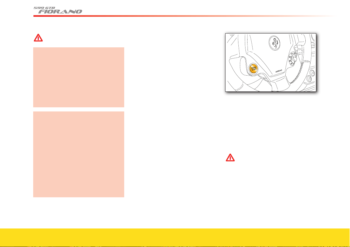
102
WARNINGWARNING
Hold button R down, until the letter
R appears on the display.
Release the UP and DOWN levers and
the button R soon after the gear
engaged is shown on the display.
Continued operation may activate the
failure warning light (see page 92) and
the acoustic alarm.
Do not operate the system with the
engine off, to prevent discharging the
battery.
Also avoid unnecessary gearshifting
when the engine is off, in order to
prevent the system pump from
overheating.
If the engine compartment lid is open
or not properly closed, none of the
gears can be engaged.
When the vehicle is stationary, with the
driver-side door open or not properly
closed and the brake pedal released,
the system disengages the gear
engaged after approximately two
seconds.
Starting and warming up the engine
(F1 gearbox)
- Ensure that the handbrake is engaged
and that the doors are closed.
- It is advisable to keep the brake pedal
pressed when starting the engine.
- Do not push the accelerator pedal.
- Turn the ignition key to position II and
wait until the words Check OK are
viewed on the TFT display. If the words
Check OK do not appear, turn the key
back to position
0, wait a few seconds
and repeat the procedure.
- The vehicle is always started in “AUTO
easy exit” mode, unless it was turned off
with the gearbox in “AUTO” mode.
- Press the ENGINE START
button and
release it as soon as the engine starts. Do
not hold the ENGINE START button
down for a long time.
- After the engine has started, the words
ENGINE ON will be displayed.
Do not hold the ENGINE START button
down for a long time.
If the engine does not start, turn the key
back to position 0 and wait until the gear
display turns off before repeating the
procedure.
WARNINGWARNING
Hold the brake pedal down while
starting the engine.
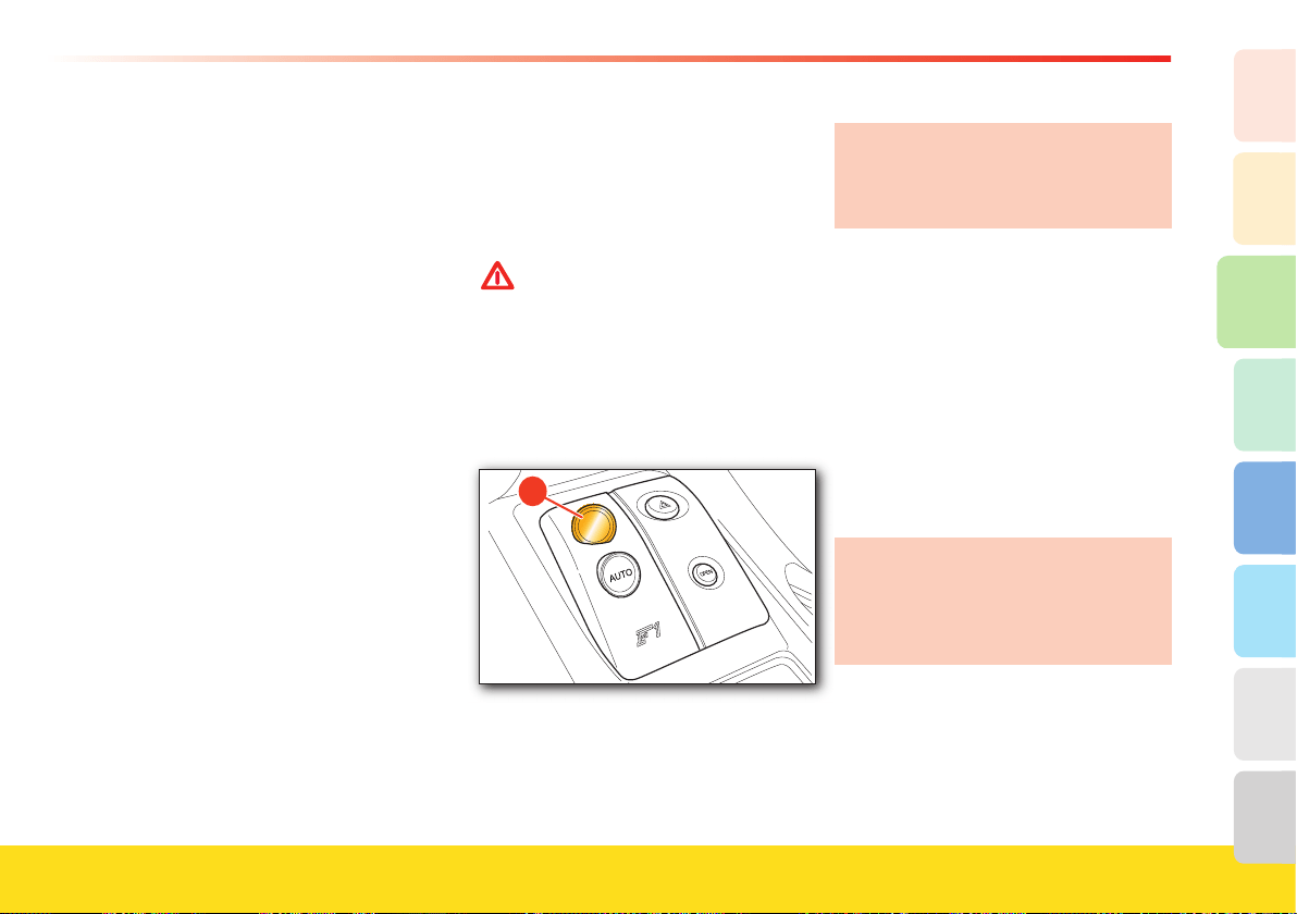
103
About your vehicle
2
1
3
8
7
6
5
4
If the engine fails to start after several
attempts, check for one of the following
causes:
- insuffi cient speed of the starter motor
(dead battery)
- ignition device faulty
- electrical contacts faulty
- fuel pump fuses blown.
Do not run the engine at high speeds
until the engine oil temperature has
reached at least 149–158 °F (65÷70 °C),
approximately.
Driving the vehicle (F1 gearbox)
With the engine started, the vehicle
stationary and the brake pedal pushed,
pull the right-hand UP lever towards the
steering wheel to engage 1st gear.
WARNINGWARNING
Use 1st gear for parking or for
starting uphill.
Release the brake pedal and press the
accelerator to start off.
As soon as a gearshift is requested (with
the vehicle in motion) using the levers UP
or DOWN, the system will exit the “AUTO
easy exit” mode.
R
�
With the engine on and the vehicle
stationary, you can shift directly from 1st to
R by pressing button R on the center
console, and from reverse to 1st gear by
pulling the UP lever towards the steering
wheel.
When reverse gear is engaged, an
acoustic safety signal beeps
intermittently for the entire time that R
remains engaged.
If the system automatically engages 2nd
gear when shifting from R to 1st gear,
jamming has occurred on
1st gear.
Therefore, this is not a malfunction, as it
falls within the system operation logic.
For the same reason, when shifting from
1st gear to R, the system will
automatically engage N if the gear has
jammed.
During prolonged stops with the engine
running, it is advisable to keep the
gearshift in
N.
On downhill stretches, if you allow the
vehicle to move forward in N, when an
UP-shift
is requested, the system will
engage a gear in relation to the vehicle
speed.
For safety reasons, the system activates the
buzzer and automatically shifts to N
when, with the vehicle stationary, the
engine running and a gear engaged:
- the brake or the accelerator pedal is not
depressed for more than 50 seconds
104
- the brake pedal is depressed for more
than 10 minutes
- the door is opened without depressing
the brake or the accelerator pedal
- the engine compartment lid is opened.
WARNINGWARNING
The buzzer may also sound to warn
the driver that the clutch is starting
to overheat. This may occur if you
use the accelerator pedal when the
vehicle is stationary on a hill or
during the “pick-up” maneuver.
In these cases, you must release the
accelerator pedal and only use the brake
pedal to keep the vehicle stationary or,
where possible, start off immediately.
Important
- When the vehicle is stationary with a
gear engaged, always hold the brake
pedal depressed until you are ready to
move.
- Do not “rev the engine” using the
accelerator pedal to start off.
- Shift to reverse only when the vehicle
has come to a complete stop and
keeping the brake pedal depressed.
If the vehicle is stopped on an uphill
stretch, do not use the accelerator
pedal to keep it stationary. Use the
brake and press the accelerator pedal
only when ready to move.
If the accelerator pedal is fully depressed
very quickly when the CST system is off,
the vehicle will have a “performance” start
with skidding of the driving wheels, even
in good grip conditions.
Gearshifting (F1 gearbox)
UP-shifting
Use the right-hand UP lever, even without
releasing the accelerator pedal.
An UP-shift request will not be accepted
if engagement of the requested gear
would force the engine to run at too low
RPM (underrevving) or if an UP-shift
is
already in progress due to engine
overrevving. Gearshifting will be
increasingly faster as the performance
requested by the driver increases, i.e., as
both the engine RPM and the travel of
the accelerator pedal increase.
In any event, it is advisable to:
- Shift gears without releasing the
accelerator pedal if it is depressed
- Wait until gearshifting has been
completed before requesting the next
shift, avoiding a rapid sequence of
multiple requests.
UP-shift due to engine overrevving
The system “automatically” engages a
higher gear if the accelerator pedal is
depressed and the engine approaches the
“runaway speed rate” (overrevving). This
will not occur when the system is in
RACE mode and the CST
system is off.
DOWN-shifting
Use the left-hand DOWN lever, even
without releasing the accelerator pedal.
A DOWN-shift request is not accepted if
engagement of the requested gear would
force the engine beyond a certain RPM or
if a DOWN-shift is already in progress
due to a too low engine RPM.
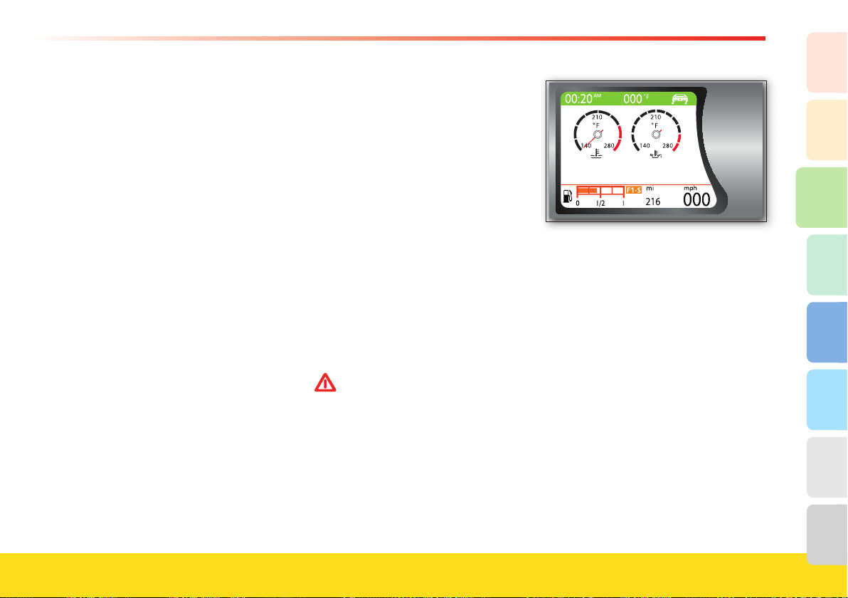
105
About your vehicle
2
1
3
8
7
6
5
4
In any event, it is advisable to:
- shift gears without releasing the
accelerator pedal if it is depressed
- if a DOWN-shift is requested to start
overtaking, where rapid acceleration is
required, press the accelerator pedal just
before moving the lever
- wait until gearshifting is completed
before requesting the next one, avoiding
a rapid sequence of multiple requests.
DOWN-shift due to engine underrevving
- The system shifts down the gears
“automatically”, if the engine runs below
the minimum RPM, set at 1250 RPM.
- The DOWN-shift request from the lever
is ignored if gearshifting due to a too
low engine RPM (underreving) is
already in progress.
N (Neutral) request
If necessary,
N can be requested at any
speed.
Subsequently, if UP-shifting is requested,
the system will engage the gear most
suited to the speed of the vehicle.
F1 – SUPERFAST gearshifting
Using the elastic power of the transmission
devices and the integrated electronic
management of engine and gearbox, the
F1-SuperFast system enhances vehicle
performance.
The different gearshifting stages (torque
reduction and clutch disengagement, gear
disengagement and engagement and
subsequent clutch re-engagement) are
actuated in sequence.
This results in extremely fast gearshifting,
which is reduced to 100 ms (measured as
“acceleration gap”).
F1-SuperFast
gearshifting activates only
in the following conditions:
- “Manettino” set to SPORT
, RACE or
CST OFF
WARNINGWARNING
RACE mode must be used only on
race tracks.
- engine running at > 5000 RPM
- lateral acceleration
< 0.9 g
- no traction control
- engine water temperature
> 158 °F (70 °C)
and engine oil temperature
> 59 °F (15 °C).
A message on the TFT display will inform
the driver that F1-SuperFast gearshifting is
available.
F1-SuperFast gearshifting is not available
in the following conditions:
- “Manettino” set to ICE
or LOW GRIP
- engine running at
< 5000 RPM
- lateral acceleration
> 0.9 g
- skidding of the rear wheels
- traction control activated
- engine water temperature
< 158 °F (70 °C)
and engine oil temperature < 59 °F (15 °C).
Stopping the vehicle (F1 gearbox)
When the vehicle stops, the system
automatically engages 1st gear (unless N
has already been requested
). With the
vehicle stationary and the engine running,
hold the brake pedal down until you are
ready to start off again.
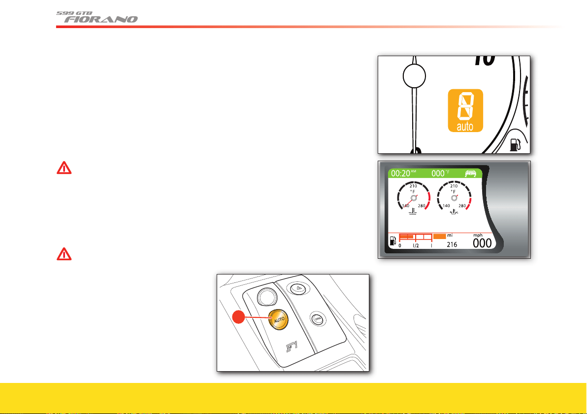
106
Turning off the engine and the
system (F1 gearbox)
The engine can be turned off either with
the gearshift in
N
or a gear engaged.
After turning the ignition key from
position II to position 0, the display will
remain on for a few more seconds to
display the gear engaged. If the gearshift
is in
N
, a buzzer will sound.
WARNINGWARNING
Do not start the vehicle before the
display has turned off.
Never leave the vehicle with the
gearshift in N. Engage a gear (1st or
R), check that the display is not
fl ashing and always apply the
handbrake. Never leave the vehicle
with the engine running.
WARNINGWARNING
Never remove the key when the
vehicle is moving! The system and
the display will remain active, but
malfunctioning, until the vehicle is
stopped. In addition, the steering
wheel will lock automatically with
the fi rst turn of the steering wheel.
In this case, the failure warning light will
illuminate (see page 92) and, before
starting off again, the system and the
display must be turned off and the
“Starting” procedure repeated.
In any event, it is advisable to:
-
turn off the engine and the system,
holding the brake pedal depressed
- do not request a gearshift while the
system is turning off.
Other system functions
(F1 gearbox)
“Automatic gearshift” mode
This mode is activated by pressing the
AUTO
A
button on the center console.
Activation is indicated by the word AUTO
shown on the gear display, on the
instrument panel and on the TFT display.
R
�
The system will automatically shift the
gears UP and DOWN according to the
vehicle speed, the engine RPM and the
torque/power requested by the driver.
When the vehicle is stationary, if the driver
requests N, 1st gear or R, the system will
not shift from “Automatic” to “Manual”.
The “Automatic” mode can only be exited
by operating the AUTO
A
control button.
In “Automatic” mode, if you operate the
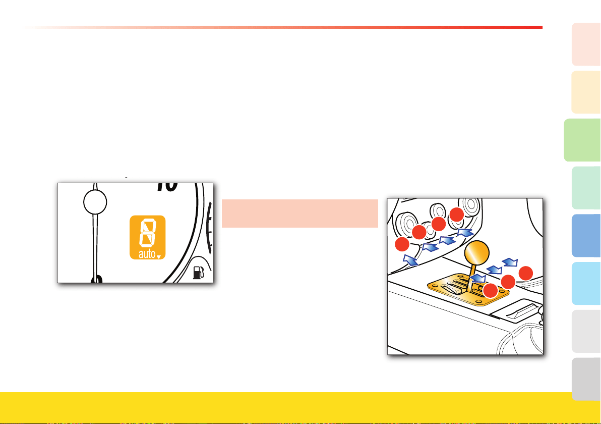
107
About your vehicle
2
1
3
8
7
6
5
4
UP and DOWN levers, the system will
allow you to shift gears using the lever,
but it will then switch back to “Automatic”
mode.
“AUTO easy exit” mode
The vehicle is always started in “AUTO
easy exit” mode, unless it was turned off
with the gearbox in “AUTO” mode.
Activation is signaled by the word
AUTO
▼
appearing on the gear display,
on the instrument panel.
on the instrument panel.
The system will automatically shift the
gears UP and DOWN according to the
vehicle speed, the engine RPM and the
torque/power requested by the driver.
In “AUTO easy exit” mode, if you operate
the control levers UP and DOWN (with
the vehicle in motion) the system will exit
“AUTO” mode to switch to “Manual”
mode.
If you then request “AUTO” mode by
pressing the control button
A
AUTO, the
system will use all the “Automatic” mode
gearshifting features.
Push start (F1 gearbox)
In the event that the ignition system
malfunctions, you can “push start” the
vehicle as follows:
- perform the “system starting” procedure
(see page 100)
- with the gearshift in N, as the vehicle
speed is increasing, request an UP-shift.
This procedure should be avoided
unless there is an emergency situation!
Restarting the engine (F1gearbox)
In the event that the engine is turned off
accidentally, restart it using the ENGINE
START button, after turning the key to
0
and then to II: the engine will start
immediately.
Starting and driving the vehicle
(Mechanical Gearbox)
Starting the engine
Before starting the engine, make sure that
the alarm system and all electrical devices
with high power absorption are turned
off.
- Ensure that the handbrake is engaged.
- Put the gearshift lever into neutral.
- Fully depress the clutch pedal without
pushing the accelerator.
1
R
3
5
2
4
6
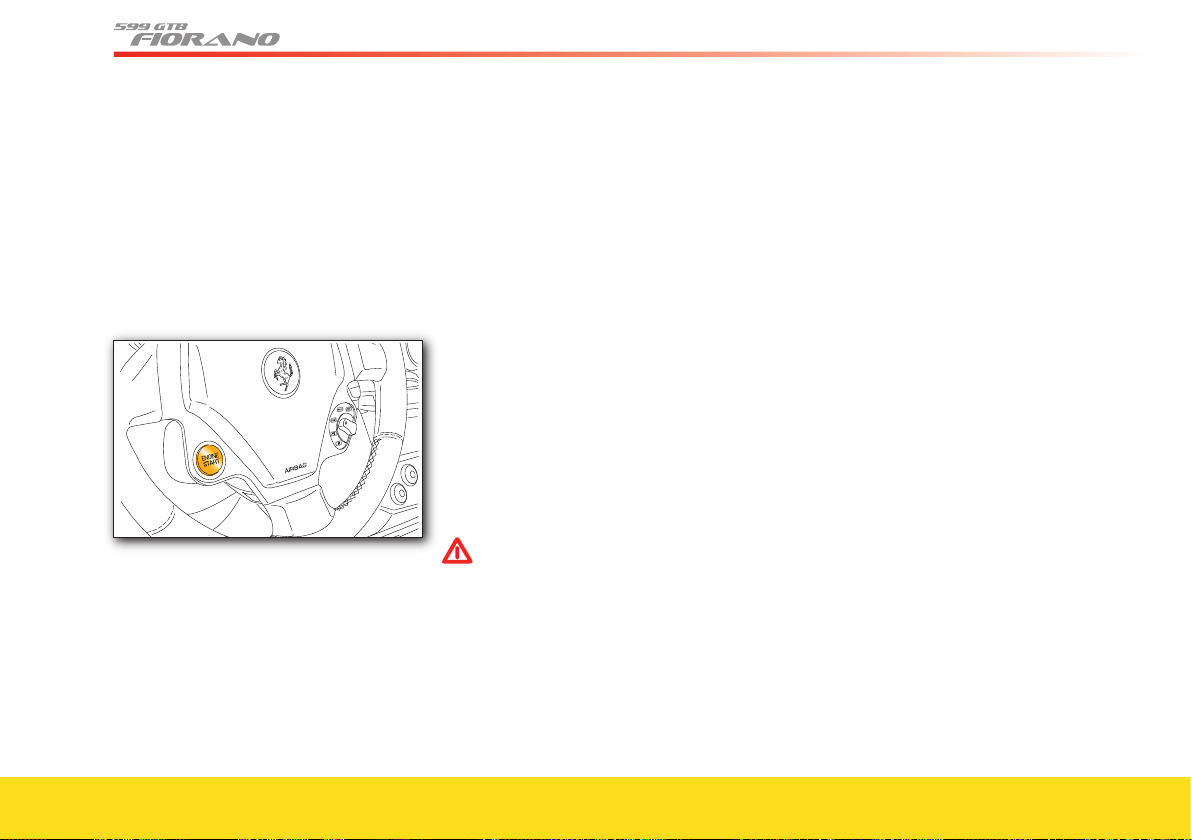
108
- Turn the ignition key to position II and
wait until the words Check OK are
viewed on the TFT display. If the words
Check OK do not appear, turn the key
back to position
0, wait a few seconds
and repeat the procedure.
- Press the ENGINE START
button and
release it as soon as the engine starts. Do
not hold the ENGINE START button
down for a long time.
If the vehicle fails to start, turn the key
back to position 0 before repeating the
procedure.
- After the engine has started, the words
ENGINE ON will be displayed.
If the engine fails to start after several
attempts, check for one of the following
causes:
- insuffi cient speed of the starter motor
(fl at battery)
- ignition device faulty
- electrical contacts faulty
- fuel pump fuses blown.
Do not run the engine at speeds higher
than 4000 RPM until the engine oil
temperature has reached at least
149 - 158 °F – 65 - 70 °C.
Driving the vehicle
(Mechanical Gearbox)
When the engine has started:
- Fully depress the clutch pedal and move
the gearshift lever to 1st gear.
WARNINGWARNING
Use 1st gear for parking or for
starting uphill.
- Completely release the handbrake.
- Slowly release the clutch pedal while
gradually accelerating.
- Then engage the other gears, fully
depressing the clutch pedal and moving
the gearshift lever into the next position.
When shifting down, be careful not to
exceed the maximum permitted engine
RPM (indicated on the tachometer in the
red area).
- Engage reverse gear only when the
vehicle is stationary: push the gearshift
lever downwards and then move it to
the left and forward.
While driving
(Mechanical Gearbox)
Never drive, not even downhill, with the
tachometer pointer near the peak engine
speed.
When the tachometer pointer approaches
peak speed (the red zone), the driver
must be very careful to avoid exceeding
that limit.
In normal conditions, all the red and
amber warning lights (for the suspension
and ASR systems) on the multi-function
display must be off. If on, these lights
indicate a malfunction in the
corresponding system.
Ensure proper functioning of the various
devices by checking the relative control
gauges.
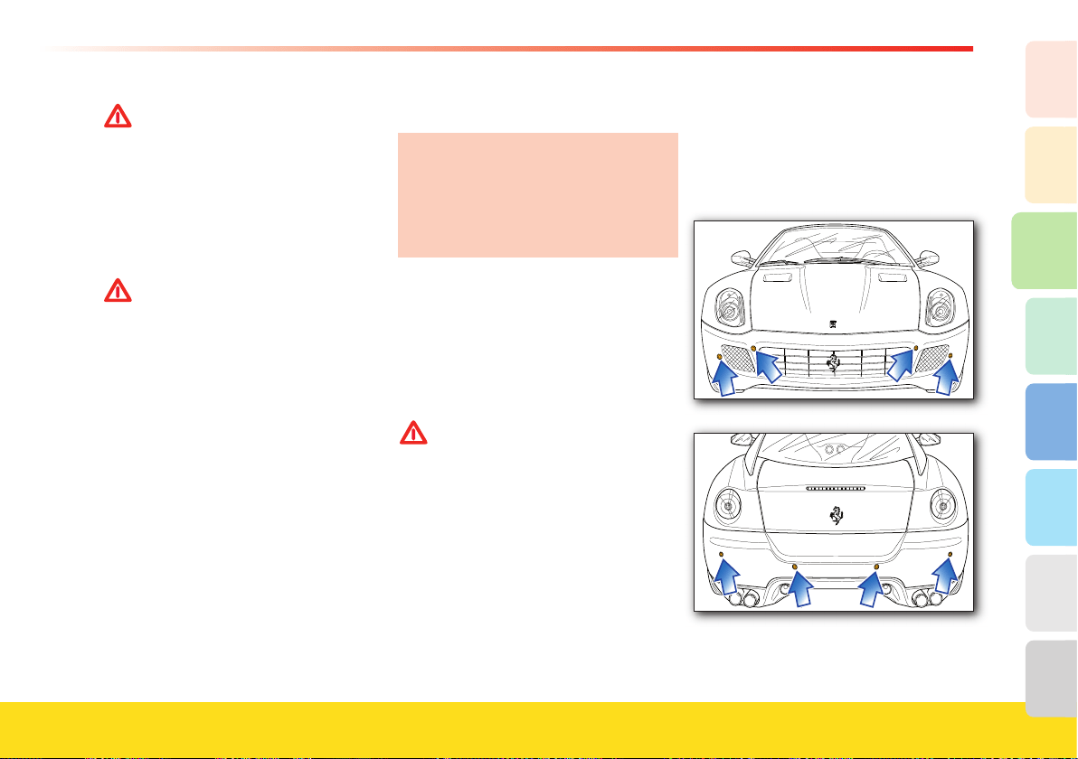
109
About your vehicle
2
1
3
8
7
6
5
4
WARNINGWARNING
Continuing to drive when a red
warning light is on could cause
serious damage to the vehicle and
affect its operation and performance.
After sports-style driving, let the
engine idle for several minutes
before turning it off, in order to
stabilize the temperatures.
WARNINGWARNING
Do not coast downhill with the
engine off, as the servo brake will no
longer function due to the vacuum
decrease and thus, after a less
braking attempts, the system will
become ineffi cient.
Parking
Apply the handbrake, put the gearshift
lever into 1st, whether parking uphill
or downhill, turn the wheels inwards
and turn off the engine (these
procedures are valid for all versions,
both with mechanical and F1 gearbox).
As the 1st gear is the most reduced, it is
more suited to use the engine as a brake.
When parking on a steep slope, use a
wedge to block the wheels.
Never leave the ignition key in position
II.
Always remove the key when getting out
of the vehicle.
WARNINGWARNING
Never leave children unattended in
the vehicle.
Do not park the vehicle on
fl ammable materials (e.g., paper,
grass, dry leaves, etc.). They could
catch fi re if they come into contact
with hot parts of the exhaust system.
Do not leave the engine running
with the vehicle unattended.
Parking maneuver
To assist the driver during parking
maneuvers, the vehicle can come
equipped with optional sensors, located in
the front and rear bumper.
110
WARNINGWARNING
To help ensure the system proper
functioning, the sensors positioned
on the bumper must be kept clean
(remove any mud, dirt, snow or ice).
When approaching obstacles found in
front or behind the vehicle, the parking
sensors provide the driver with
information on their distance.
The driver receives information about the
presence and distance of the obstacles
both by means of acoustic signals, the
tone frequency of which increases as the
obstacle gets closer, and by means of
visual warnings on the TFT display (see
the “Carrozzeria Scaglietti” User’s
Manual).
By supplementing the driver’s direct
visual information with that provided by
the system acoustic signals and visual
warnings, potential collisions can be
avoided during maneuvers.
WARNINGWARNING
However, the driver remains fully
responsible for parking maneuvers
and in other potentially dangerous
situations. The system has been
designed only as a supplementary
aid during parking maneuvers, since
it allows the driver to detect
obstacles outside his field of vision.
Use of the sensors therefore does
not mean that the driver can be less
careful and attentive and not watch
out for persons and obstacles during
parking maneuvers.
The parking system sensors, housed in the
rear bumper, are activated automatically,
with the key at position
II, when reversing.
If the vehicle is equipped with front
sensors, these can be activated by pressing
the relative button on the center console.
When reverse gear is engaged, an acoustic
signal (beep) warns the driver that the
system is active.
The system then begins to beep as soon
as an obstacle is detected, and the tone
frequency increases as the vehicle
approaches the obstacle.
When the obstacle is located at a distance
of less than 15.7 in. (40 cm), the beep is
continuous.
The warning beep stops immediately if
the distance between the vehicle and the
obstacle increases.
The tone cycle is constant if the distance
measured by the central sensors remains
unaltered.
For the TFT display graphic configuration,
please consult the “Carrozzeria Scaglietti”
User’s Manual.
Cleaning the sensors
When cleaning the sensors, take special
care not to scratch or damage them;
therefore, do not use dry, rough or hard
cloths.
The sensors must be washed with clean
water, possibly with car shampoo added.
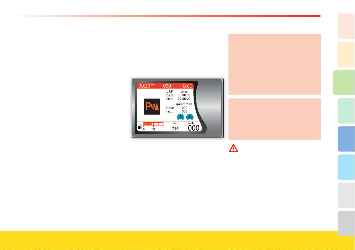
111
About your vehicle
2
1
3
8
7
6
5
4
In car-washes which use steam jet or high
pressure cleaning machines, keep the
nozzle at least 4 in. (10 cm) away from
the sensors.
Should you need to repaint the bumper
or in case of paint touch-ups in the sensor
area, please contact exclusively your
Authorized Ferrari Dealer. Incorrect
painting/touch-ups could affect the
parking sensor operation.
Sensor range
The sensors allow the system to monitor
the rear of the vehicle, as their position
covers the central and lateral zones at the
rear of the vehicle.
In the event of an obstacle located in a
mid area, this will be detected at distances
of less than 55 in. (1.40 m), depending on
the type of obstacle and its dimensions.
If the obstacle is located in a lateral
position, it will be detected at distances of
less than 31.5 in. (0.8 m).
Failure signals
The system ECU checks all of the
components every time reverse is
engaged.
A parking sensor system failure will be
indicated on the TFT display.
In the event of a failure warning signal,
stop the vehicle and turn the ignition key
to position 0 (Stop). Then try to clean the
sensors or move away from any
ultrasound sources (e.g., pneumatic truck
brakes or pneumatic hammers) and turn
the key back to II. If the situation causing
the malfunction has been corrected, the
system starts working again and the
failure warning buzzer stops. If the failure
warning buzzer remains on, contact your
Authorized Ferrari Dealer
to have the
system checked.
During parking maneuvers, always take
the greatest care as there may be
obstacles located above or underneath
the sensors.
In certain circumstances, objects
located near the rear of the vehicle are
not detected by the system and
therefore may damage the vehicle or
be damaged themselves.
The signals transmitted by the sensors
can also be altered by damage to the
sensors or by dirt, snow or ice on the
sensors or even by ultrasound systems
(e.g., pneumatic truck brakes or
pneumatic hammers) in the vicinity.
WARNINGWARNING
The driver is fully responsible for
parking and other potentially
dangerous maneuvers. During these
maneuvers, always make sure there
are no people (especially children)
or animals in the maneuvering area.
The parking sensors must be
considered an aid for the driver
who, in any case, must never take
less care during potentially
dangerous maneuvers, even if they
are performed at low speeds.
112
Proper driving
For proper driving, it is essential that
the driver be aware of the best driving
techniques suited to various
circumstances. Always try to prevent
dangerous situations by driving with
caution.
Before you drive
- Adjust the position of the seat, steering
wheel and rear-view mirrors, in order to
obtain the best driving position.
- Adjust the backrest so that your chest is
upright and your head is as close to the
headrest as possible.
- Carefully adjust the headrest so that
your head, and not the neck, is resting
against it. Make sure that nothing (e.g.,
floor mat, etc.) is blocking the pedals.
- Check that the lights and headlights are
working properly.
- Make sure that any child restraint
systems (e.g., child seats, etc.) are
properly fixed on the passenger seat.
- Your reflexes are quicker if you eat
lightly before driving: avoid heavy meals
before a trip.
- Do not drink alcoholic beverages before
and during the journey.
At regular intervals, check the following:
- Tire pressure and condition.
- Engine oil level.
- Engine coolant level and system
condition.
- Brake fluid level.
- Steering fluid level.
- Windshield washer fluid level.
When traveling
- Caution is the number one rule for safe
driving, which also means you should
take other people’s behavior into
consideration.
- Follow the Road Regulations of the
country in which you are driving, and
always respect the speed limit.
- Always make sure that the driver and
the passengers have their seat belts
fastened and that all children are
traveling in suitable child seats.
- Good personal physical conditions
ensure you can drive long distances
safely.
WARNINGWARNING
Drunk driving, or driving under the
influence of drugs, alcohol or certain
medicines is extremely dangerous
for yourself and others.
Traveling without your seat belt
fastened increases the risk of serious
injury and death in the event of a
collision. Always fasten the seat belt
and the child seat, if any.
Deactivate the passenger’s airbag
(where possible) if a child seat is
fitted on the front seat.
Do not travel with objects lying
around on the floor, especially in
front of the driver’s seat: in the event
of braking, these could slide under
the pedals, making it impossible to
brake or accelerate.
Additionally, ensure that any floor
mats fit correctly.
Water, ice and salt spread on icy
roads may deposit on the brake discs
and reduce the efficiency of the
initial braking.
113
About your vehicle
2
1
3
8
7
6
5
4
- Make regular stops to loosen up your
limbs and refresh yourself, and avoid
driving for hours on end.
- Keep a constant air circulation in the
passenger compartment.
- Never coast downhill with the engine
off: in these conditions the engine brake,
servo brake and power steering are
inefficient, braking requires greater
pressure on the pedal and steering will
be harder.
Driving at night
When you are traveling at night, follow
these fundamental rules:
- Reduce speed, particularly on dark
roads.
- Driving conditions are more demanding
at night, so take particular care.
- If you start feeling tired or sleepy, stop
immediately: to continue driving would
be a risk for yourself and for others.
Continue only after you have had a rest.
- At night, it is difficult to evaluate the
speed of the vehicles by seeing their
lights only: keep at a greater safety
distance than you would during the day.
- Use the high beams only outside of
urban areas and when you are sure that
they will not disturb other drivers.
- Turn off the high beams when you see
oncoming vehicles and use the low
beams.
- Keep the lights and headlights clean.
- Watch out for animals crossing the road
when traveling outside urban areas.
Driving in the rain
Rain and wet roads can cause hazardous
situations.
All maneuvers are more difficult on a wet
roads, as the tires have significantly less
grip on the road. This means that the
braking distances increase considerably
and road-holding decreases.
Below is some advice for driving in the
rain:
- Keep a greater safety distance between
yourself and the other vehicles and
reduce your speed.
- When it is raining very hard, visibility is
also reduced. In these cases, to make
yourself more visible to others, turn on
the low beams even during the day.
- Do not drive through puddles at high
speeds as you do not know how deep
they may be. Traveling through a puddle
at high speed can result in losing control
of the vehicle (“aquaplaning”): hold the
steering wheel firmly.
WARNINGWARNING
If the road is wet, reduce your speed
to avoid “aquaplaning” phenomena,
during which the tire no longer
touches the road surface. This is due
to the fact that, when the road is
very wet and the vehicle speed is
high, the side channels of the tire
tread, because of their particular
shape or insufficient depth, are not
capable of removing all of the water
channelled, so that a layer of water
exists between the road surface and
the tire. The fluid pressure generated
is so high as to support the vehicle’s
weight, making it impossible for the
driver to control the vehicle.
- Use the ventilation system to defog the
windshield (see page 124) and to avoid
visibility problems.
- Periodically check the condition of the
windshield wiper blades.

114
Driving in fog
Whenever possible, avoid driving if the
fog is thick. If you have to drive in misty
conditions, or if there is thick fog or fog
banks, follow these rules:
- Keep a moderate speed.
- Turn on the low beams, also during the
day, and use the rear fog lights. Avoid
using the high beams.
WARNINGWARNING
On stretches where visibility is good,
turn off the rear fog lights, as they
are very bright and may be annoying
for the occupants of the vehicles
behind you.
- Remember that fog makes the road damp
and therefore all maneuvers are more
difficult and braking distances are longer.
- Keep a safe distance from the vehicle in
front of you.
- As much as possible, avoid suddenly
changing speed and direction.
- As much as possible, avoid overtaking.
- In the event of an emergency stop, (e.g.,
failures, inability to proceed due to poor
visibility conditions, etc.) try to leave the
main driving lane. Then turn on the
hazard warning lights and, if possible, the
low beams. When approaching another
vehicle, sound the horn rhythmically.
Driving on mountain roads
Below is some advice for driving on steep
mountain roads:
- To prevent the brakes from overheating
when driving downhill, use the engine
to brake by engaging a lower gear.
- Never coast downhill or drive downhill
with the engine off or in neutral, nor
with the ignition key removed from the
steering column.
- Drive at a moderate speeds and do not
“cut” corners.
- Remember that overtaking uphill is
slower and requires a longer free stretch
of road. If you are overtaken when
driving uphill, ensure that the other
vehicle can pass easily.
Driving on snowy or icy roads
Below is some advice for driving in these
conditions:
- Keep a very moderate speed.
- Keep a safe distance from the vehicles in
front of you.
- Fit snow tires approved for the vehicle.
- Given the poor grip, use the engine
brake as much as possible and avoid
sudden braking.
- Avoid sudden acceleration and sharp
changes in direction.
- During the winter season, even
apparently dry roads can have icy
sections.
Therefore, be careful when driving along
stretches of road in the shade as there
may be icy patches.
Driving with the “ABS” braking system
The ABS system assists the driver as
follows:
- It prevents the wheels from locking and
skidding during emergency braking,
particularly in low-grip conditions.
- It allows braking and changing direction
at the same time. This feature is affected
by the physical limits and lateral grip of
the tires.
- When the ABS is activated, you will feel
a slight pulsing of the brake pedal
during emergency braking or in low-grip
conditions. Do not release the pedal but
continue to push it to give continuity to
the braking action.
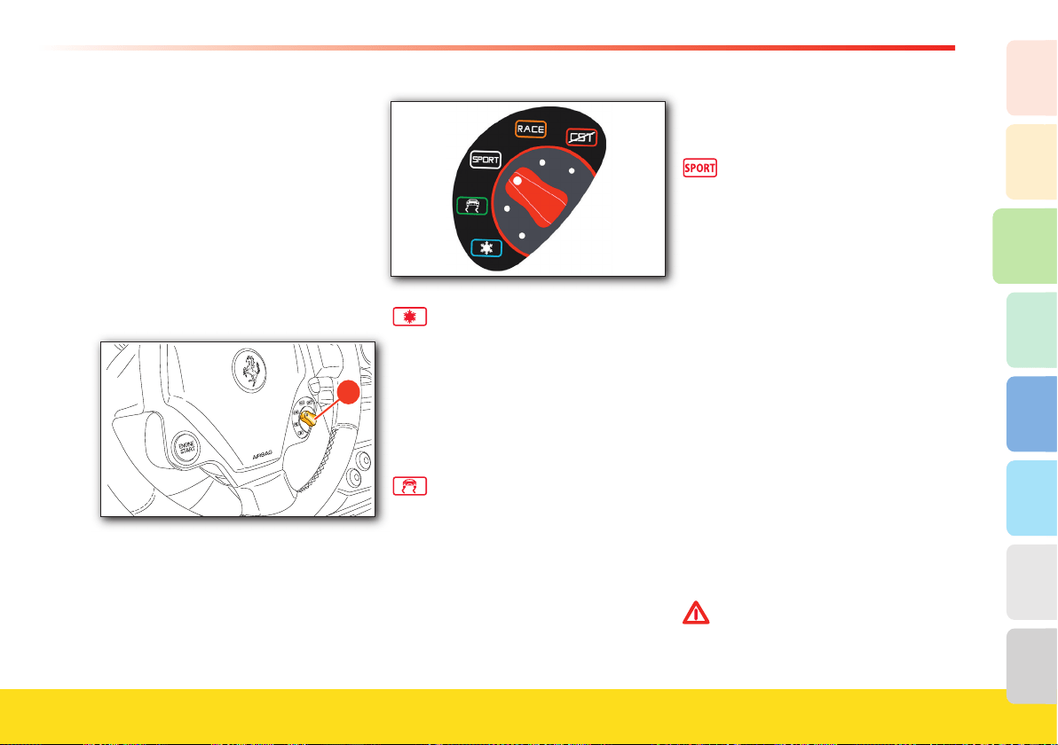
115
About your vehicle
2
1
3
8
7
6
5
4
- The ABS system is designed to prevent
the wheels from locking, but it does not
increase the physical limits of grip
between the tires and the road: keep a
safe distance from the vehicles ahead
and reduce speed before curves.
Driving using the “Manettino” (driving mode
control switch)
The “Manettino”
A on the steering wheel,
allows the driver to use the vehicle
potential in a quick and easy way.
�
There are fi ve modes available, which can
be selected according to the grip level
(from low to high) and consequently to
the level of driving assistance required
(from high to none).
In ICE mode, increased stability -
which is essential for driving on
roads where grip is very low (e.g.,
snow or ice) - has priority over
performance, which is signifi cantly
reduced. Traction stability control
(CST) is at the maximum level
(Level 1). The vehicle has an
extremely “smooth” behavior.
Low Grip mode ensures stability
on both dry and wet roads.
It is
therefore recommended on roads
where grip is poor (e.g., rain),
slippery or extremely uneven roads,
but also to enhance comfort during
city driving. In this confi guration,
unlike the previous one, the driver
may drive the vehicle using the
gearbox as desired.
Suspension damping is optimized
to enhance driving comfort and the
CST
system remains set to the
previous level.
SPORT mode is the basic driving
mode for the vehicle and provides
the best compromise between
stability and performance. This
setting helps ensure stability only
in dry-high grip conditions and not
on low-grip road surfaces (in this
case, it is advisable to return to
Low Grip mode). In this mode, the
vehicle optimal performance can be
experienced on open roads. For
this reason, the suspension
damping level is shifted to a higher
one, so as to enhance performance,
handling and stability at high
speeds. Also the CST system
switches to a different level
(Level 2), offering the driver
greater driving freedom. The F1-
Trac system does not correct
engine torque signifi cantly when in
SPORT mode (for this reason, it
does not ensure stability on low-
grip road surfaces).
WARNINGWARNING
RACE mode must be used only on
race tracks.
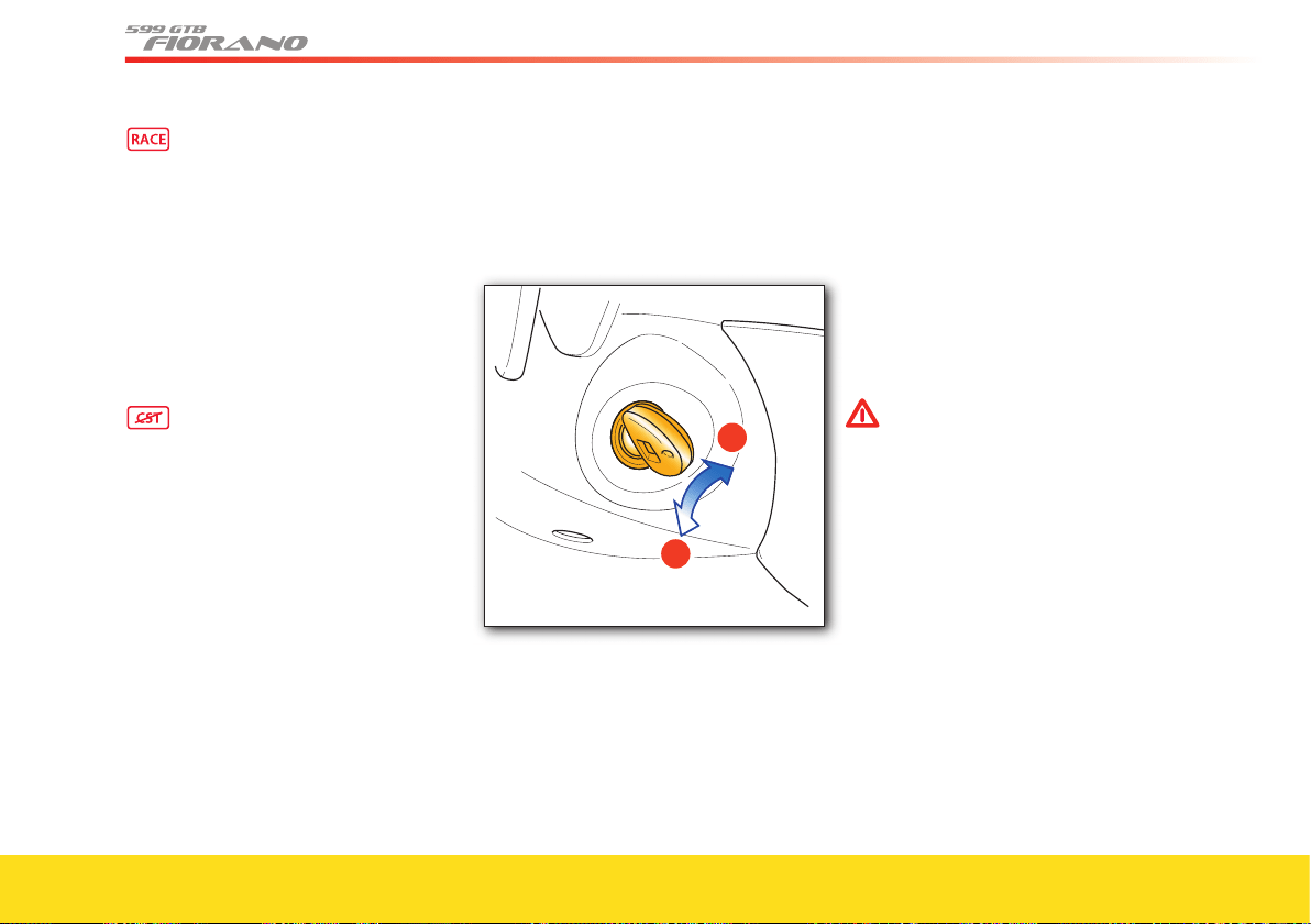
116
On vehicles equipped with F1
gearbox, gearshifting is faster so as
to reduce gear change times as
much as possible. The CST
shifts
to Level 3 (engine power
reductions are minimal) and the
suspension stiffens further. In this
position, the driver has full control
of the vehicle and the operation of
all engine control systems is
reduced to a minimum. Stability is
not ensured.
The
CST
is deactivated. Vehicle
stability is no longer controlled,
but is completely in the hands of
the driver. The only aids that are
still active are those that cannot be
deactivated, such as the ABS and
EBD. When the brake pedal is
depressed, the VDC system is
reactivated, while the F1-Trac
system remains deactivated.
Gearshifting speed (on vehicles
with F1 gearbox) and damping
control remain the same as in
RACE
mode.
Ignition switch
The ignition key can be turned to 2
positions:
Position 0 – Stop
Engine off, key removable.
When the key is even only partially
extracted, the steering column is locked.
The hazard warning lights and the
parking lights can be activated.
To facilitate steering wheel release, turn
the steering wheel slightly in both
directions while turning the ignition key.
Position II – Ignition
Turning the key to this position, the TFT
display will check the signals coming from
the vehicle systems.
If no malfunctions are found after starting
up, the words “Check OK” will be
displayed.
WARNINGWARNING
Never remove the key when the
vehicle is moving!
The steering wheel will lock
automatically with the fi rst turn of
the steering wheel.
Always remove the key from the
ignition when you get out of the
vehicle!
Never leave children unattended in
the vehicle.
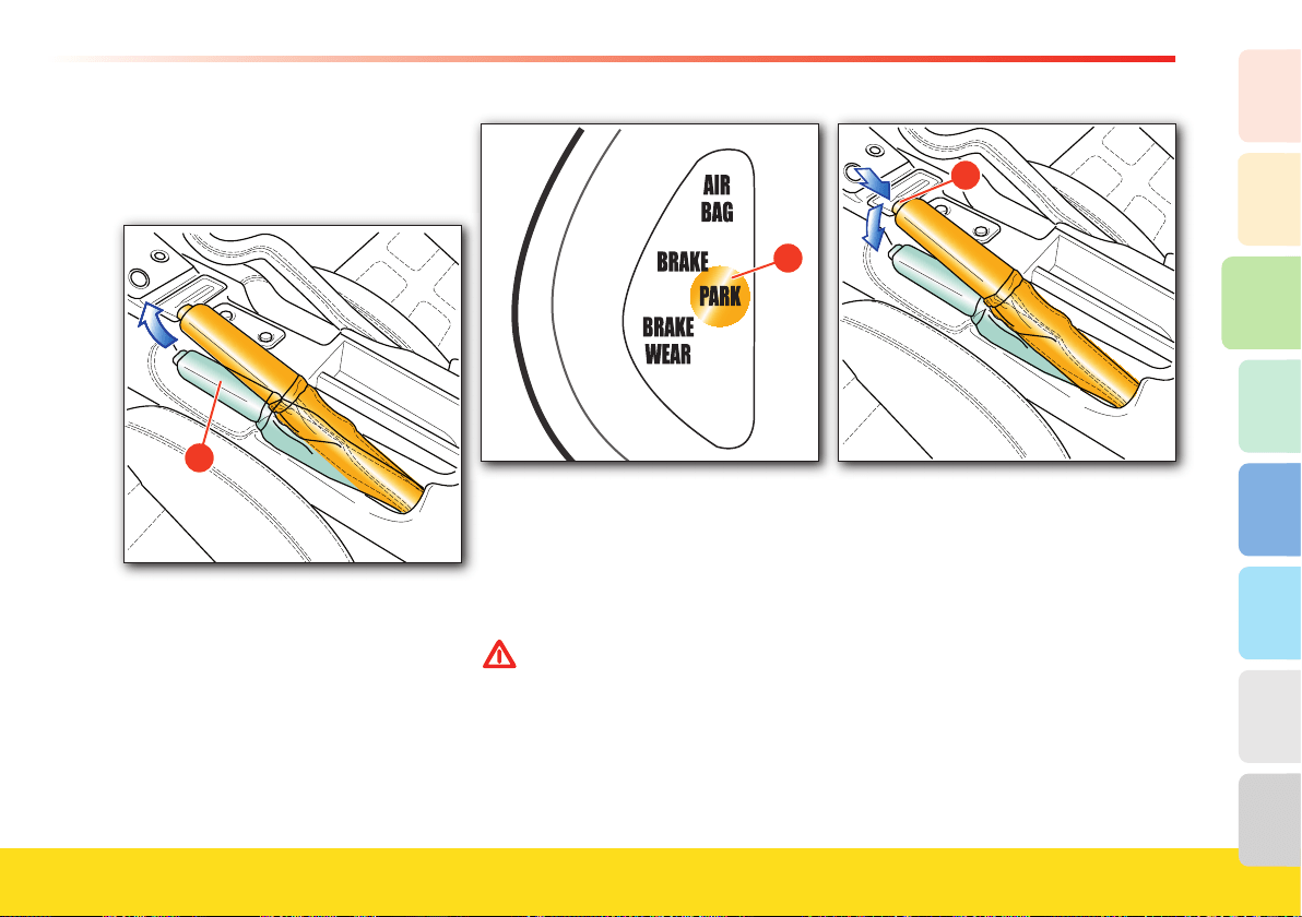
117
About your vehicle
2
1
3
8
7
6
5
4
Handbrake lever
To engage the handbrake, pull the lever A
fully upwards, until the rear wheels lock.
A
With the ignition key in position II, the
warning light B illuminates to indicate
that the handbrake is engaged.
�
To release the handbrake, slightly pull the
lever upwards and press the release
button C. Lower the lever fully, holding
the button pressed.
The warning light will turn off when the
handbrake is fully released.
WARNINGWARNING
Always apply the handbrake when
the vehicle is parked.
After hearing a series of clicks by
pulling the handbrake lever, the
vehicle should be blocked. If this is
not the case, please contact your
Authorized Ferrari Dealer
�
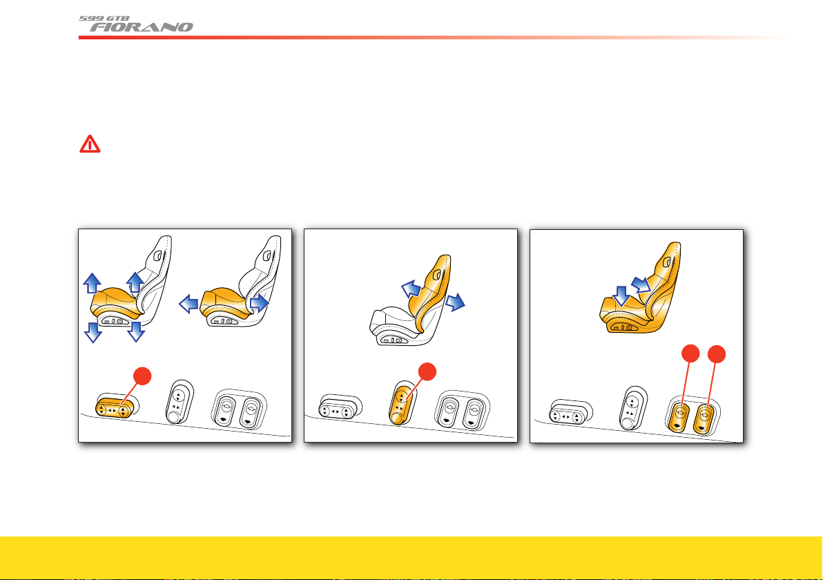
118
Adjustments
Seats
WARNINGWARNING
Never adjust the seat while driving:
you may lose control of the vehicle.
The seat position can be electrically adjust-
ed using controls
A, B, C and D.
�
Three adjustments are possible using
control A:
- forward/backward adjustment: push the
control forward or backward
- height adjustment: push the control
upward or downward
- seat inclination (tilting): push the front
end of the control upward or downward
to adjust the inclination of the front part
of the seat cushion; push the rear end of
the control upward or downward to
adjust the inclination of the rear part of
the seat cushion.
�
Use control B to adjust the seat backrest
inclination. Push the control forward or
backward to adjust the seat backrest
inclination.
Use control
C to adjust the seat cushion
sides. Push the control on the seat
symbols to increase or decrease the seat
cushion side supports.
Use control
D to adjust the seat side
support. Push the control on the seat
symbols to increase or decrease the seat
side support.
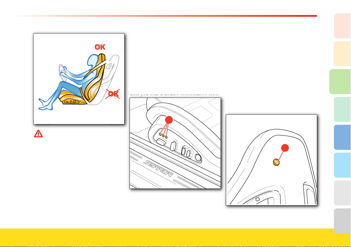
119
About your vehicle
2
1
3
8
7
6
5
4
WARNINGWARNING
Sitting in a reclined position while
the vehicle is in motion could be
dangerous. The backrest should not
be tilted too far back. The 3-point
shoulder/lap belt must be fi rmly
secured against the occupant’s body
in order to function properly.
Therefore, both the driver and
passenger’s backrests must always be
in an upright position while the
vehicle is in motion; otherwise the
3-point shoulder/lap belt would not
remain fi rmly secured against the
occupant’s body.
Serious injury could result.
Driver’s seat position memory (optional)
This device allows you to memorize and
recall three different seat positions.
You can memorize the seat position only
when the ignition is in position II
.
After adjusting the seats by means of
the controls described above, push one of
the three buttons 1, 2 or 3
E, each
corresponding to a memorizable position,
until you hear a double confi rmation tone.
until you hear a double confi rmation tone.
�
The lumbar support adjustment will not be
memorized with the seat position.
The memorization of a new seat position
cancels the one previously stored with the
same button.
To recall one of the memorized positions
when the door is open, press button 1, 2 or
3
E for about 3 seconds.
To recall the memorized position with the
door closed, press the relative button until
you hear the tone indicating that the seat
has stopped.
Backrest tilting
Press button
X to tilt the backrest forward.
X
Press button X before moving the backrest
back to its normal position.
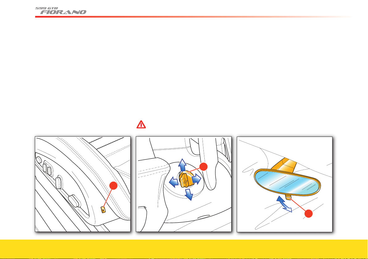
120
Seat heating system (optional)
Turn control F to activate the seat heating
function.
When this function is active for one or
more seats, the relative warning light on
the instrument panel illuminates.
Using control
F, the driver can adjust the
heating, choosing from 3 levels identifi ed
on the control with the numbers 1, 2
and 3.
�
Adjusting the steering wheel
The steering wheel height and depth can
be electrically adjusted. It can only be
adjusted if the ignition key is in
position II.
Move control
A (to the left of the steering
column) in the four directions to adjust
the steering wheel.
The steering wheel position is memorized,
together with the position of the external
rear-view mirrors, when the driver’s seat
position is stored.
WARNINGWARNING
Do not adjust the steering wheel
when the vehicle is moving.
�
To help the driver when entering or
exiting the vehicle, the steering wheel is
lifted automatically.
Rear-view mirrors
Internal rear-view mirror
This mirror can be adjusted manually.
For the anti-dazzling effect, move lever
A
forwards.
�
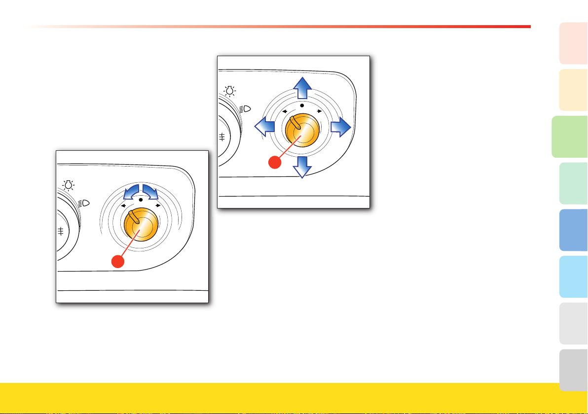
121
About your vehicle
2
1
3
8
7
6
5
4
External rear-view mirrors
These mirrors can be electrically adjusted
using control B (with the ignition key in
position II) and are equipped with
defogging elements.
1) Mirror selection: using control
B,
select the mirror you wish to adjust
(right- or left-hand).
�
2) Mirror positioning: move control B in
the four directions (up – down – right
– left) to adjust each of the rear-view
mirrors.
B
Once adjustment is complete, move the
control B into the upper central position,
where it will be locked, in order to avoid
changing the setting inadvertently.
The mirrors will yield in both directions
in the event of a collision: if necessary, the
mirrors can be pushed both backwards
and forwards.
In the models equipped with memory
seats, every time the seat position is
memorized, the external rear view mirror
position is also stored automatically, both
for the normal traveling direction and for
reverse maneuvering.
To memorize a new position of the
external rear-view mirrors, turn the
ignition key to position
II and adjust the
position of the mirrors; then engage
Reverse gear and reposition the external
mirrors to ensure optimal visibility to
perform the maneuver, then disengage
Reverse gear.
Finally, press one of the buttons 1, 2 or 3
on the seat (see page 119), each one
corresponding to a memorizable position,
until a double tone confi rms the
procedure is complete.
The new position of the external rear-view
mirrors will be automatically memorized
together with the seat position.
In addition, the mirror positions can be
adjusted for both the normal traveling
direction and for reverse maneuvering.
The mirrors must always be in the open
position while driving.

122
Air conditioning and heating
system
Operating modes
Automatic
This mode automatically adjusts the air
distribution, temperature and ventilation
levels according to the temperature set by
the user.
Partially Automatic
This mode allows the user to adjust
certain parameters manually, while others
remain automatic.
Manual
This mode allows the user to set the
values to suit the passengers’ needs.
Controls
A Left-hand temperature setting
B Air conditioning compressor
deactivation
C Left-hand air distribution setting
D Windshield defogging/demisting
E Fan speed adjustment
F Recirculation function
G Right-hand air distribution setting
H Rear window and external rear-view
mirrors defogging/demisting
I Right-hand temperature setting
J Residual heat function.
Starting
Fully automatic management: turn controls
C, E and G to the “AUT” position.
Deactivation
Turning the (fan speed) control
E to
“OFF”.
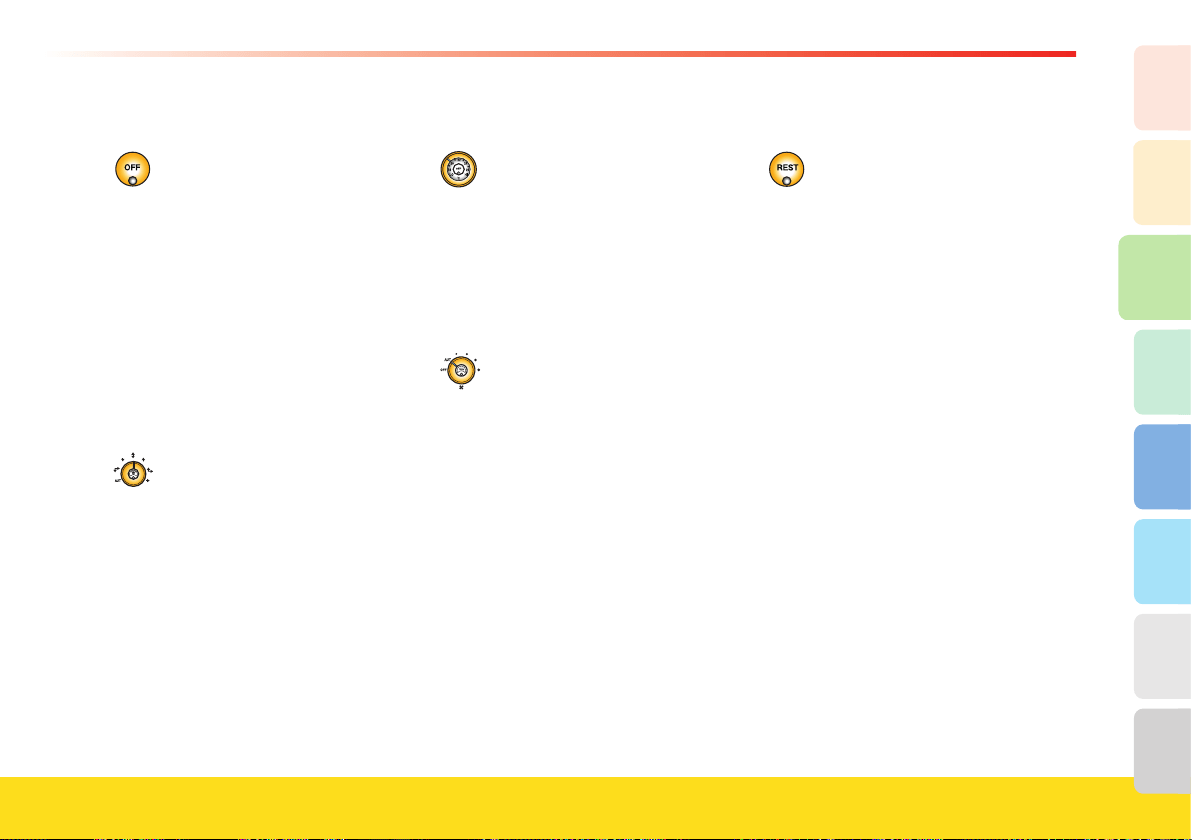
123
About your vehicle
2
1
3
8
7
6
5
4
Air conditioning control switch B
Released (LED off)
The air conditioner is on.
The air is cooled and/or only
dehumidified according to the
temperature set.
Pressed (LED on)
The air conditioner is off.
However, heating is still enabled
and will activate according to the
temperature set.
Air distribution controls C and G
They can operate in two modes:
Automatic “AUT”
The air flow distribution is
controlled by the electronic system,
depending on the ambient
conditions and the temperature set.
Manual
This is used to direct the air flow in
the six positions of the respective
areas (driver-passenger).
Temperature setting controls A and I
They are used to set the desired
temperature in the passenger
compartment.
The “LO” and “HI” (minimum and
maximum, respectively) air
temperature settings are activated at
the opposite end positions.
Fan speed control E
It has three operating modes:
Automatic “AUT”
The air flow is controlled by the
electronic system, according to the
selected temperature to be reached
and maintained.
Manual “OFF”
Turn the control to this position to
turn off the air conditioning and to
only allow air inlet from the outside
when the vehicle is moving.
Fan speed
The four setting positions allow the
occupants to select the air flow rate.
Residual heat function J
This function allows the user to
maintain the temperature set for the
passenger compartment for a
specific time (15 minutes), even
after the key has been turned to
0
(for external temperatures lower
than 77°F (25°C)).
To activate this function, press the
“REST” button before turning the
key to
0. The system will use the hot
water recirculation pump and the
first fan speed to maintain the
temperature.
124
Air recirculation switch F
Released (LED off)
The air flow comes from the outside.
In automatic mode, when outside
temperatures exceed 90 °F (32 °C),
the air recirculation feature remains
on with a 60-second pause every
twenty minutes, to refresh the air.
If you activate the
windshield
washer function, the air recirculation
feature activates for 20 seconds, to
prevent any smell of detergent
products from entering the
passenger compartment.
Pressed (LED on)
The air flow comes from inside the
passenger compartment.
The recirculation feature increases
air heating or cooling.
Prolonged use is not advisable.
Windshield defogging/demisting
switch D
Press this switch (LED on) to
activate windshield defogging/
demisting.
To deactivate this feature, press the
switch again (LED off).
Defogging/demisting switch for
rear window and external rear-view
mirrors H
Press this switch (LED on) to
activate the rear window and rear-
view mirror defogging/demisting.
If it is not deactivated within thirty
minutes after activation, this
function deactivates automatically.
It is however advisable to deactivate
it once the defogging/demisting
process is complete.
Once the internal temperature has
stabilized at the desired level, you are
advised not to change the position of the
temperature selection switch unless the
external temperature changes drastically.
The air coming out of the vents does
not correspond to the temperature
requested by the user, but is the
temperature required to maintain the
desired temperature inside the
passenger compartment.
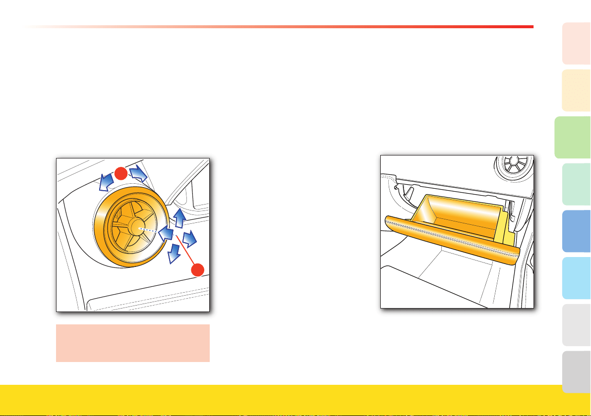
125
About your vehicle
2
1
3
8
7
6
5
4
Adjusting the air vents
The adjustable air vents are positioned on
the sides and in the center of the
dashboard.
Air fl ow direction adjustment
A.
Air fl ow rate adjustment B.
Turned counterclockwise: open.
Turned clockwise: closed.
A
B
It is advisable to keep the air fl ow
control B set to open and to direct the
air fl ow to a neutral position A.
Maintenance
The pollen fi lter must be replaced every
year, as indicated in the “Maintenance
Schedule”.
Sun radiation sensor
This sensor is positioned on the
instrument panel and it helps optimize
ventilation and temperature control inside
the compartment, depending upon the
angle of the sun rays.
Passenger compartment
accessories
Glove compartment
It is located on the passenger’s side of the
dashboard, and it is always accessible
when the key is in position II
, and for
approx. ten minutes after the key is
removed or turned to position
0.
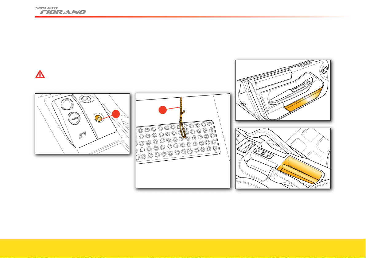
126
To access the glove compartment, push
the button A on the center console .
The glove compartment is illuminated by
a light which turns on automatically when
the door is opened.
WARNINGWARNING
Keep the glove compartment closed
while driving.
R
�
To close the glove compartment, push the
upper part of its door until you hear it
click into place.
Underneath the dashboard, in position
with the external edge of the glove
compartment, there is a safety string B for
manual opening in an emergency.
�
Other compartments
They are located on the lower part of the
doors and on the center console.
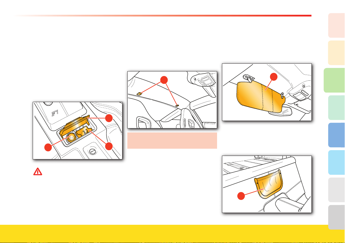
127
About your vehicle
2
1
3
8
7
6
5
4
Ashtray
To access the ashtray E or the cigarette
lighter F, push the cover G backward. To
clean the ashtray, extract it pulling it up-
ward. The cigarette lighter F is activated
by fully pushing it in. It only works when
the ignition key is in position II
. After
reaching the required temperature, the
cigarette lighter is automatically released
to its initial position and is ready to be
used.
WARNINGWARNING
Do not use the cigarette lighter seat
as a power socket for electrical items
of any kind! The cigarette lighter
reaches very high temperatures.
Handle it with care to avoid risk of
burns and fi re. It is possible to
connect the emergency tire repair
and infl ation kit ONLY for the time
necessary for the operation.
Clothing hooks
They are fi tted in the rear of the
passenger compartment. To release the
hook, press the button H. To reposition
the hook, push it upwards into its seat.
�
Move the hooks to the closed position
when they are not used.
Sun visors
The sun visors can be adjusted by moving
them downwards. There is a map pocket
I
on the back of the sun visor.
�
Map pocket
A map pocket
L is located between the
two seats.
�

1. General
2. Safety
3. About your Vehicle
4. Advice for Emergency Situations
5. Care of the Vehicle
6. Table of Notes
7. Glossary
8. Index
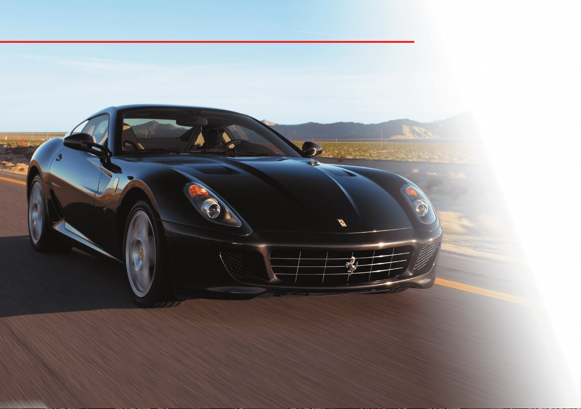
Toolkit
Replacing the headlight bulbs
Replacing the taillight bulbs
Replacing other light bulbs
Light bulbs
Replacing a fuse
Replacing a wheel
Towing hook
Fuel inertia switch
Checking the battery
Exhaust system overheating
alarm devices
Engine malfunction
alarm devices
Replacing the brake pads
and brake discs
130
WARNINGWARNING
In the event of repairs performed
using the toolkit provided, you must:
- use suitable personal protection
(e.g., gloves)
- take suitable precautions (e.g.,
when changing a tire, never lie
under the vehicle raised on the
jack)
- have the basic and specifi c skills
required for working with electrical
parts/components.
Toolkit
Toolkit bag
The toolkit bag is found in the luggage
compartment and it contains the
necessary tools for a fi rst emergency
repair work:
• set of fl at wrenches
• insulated cutting pliers
• screwdriver for slotted screws
• Phillips head screwdriver
• towing hook
• set of spare light bulbs and fuses.
Emergency tire repair and infl ation kit
In the event of a puncture or low
pressure of a tire, the kit is designed to
repair and/or infl ate the tire suffi ciently
to continue the journey.
For correct use of the repair and
infl ation kit, refer to the instruction
manual supplied with the kit.
WARNINGWARNING
Give the kit and instruction manual
supplied with the kit to the personnel
that will handle the tire repair.
WARNINGWARNING
In the event of a puncture caused by
small objects, tires can be repaired
with tears or holes that have up to a
0.16 in. (4 mm) diameter on the
tire tread and shoulder.
WARNINGWARNING
Tears on the sides of the tire cannot
be repaired.
WARNINGWARNING
Do not use the tire repair kit if the
tire is damaged after driving with a
fl at tire.
WARNINGWARNING
If the wheel is damaged and has
caused an air leakage, the tire cannot
be repaired.
131
Advice for Emergency situations
4
2
1
3
8
7
6
5
WARNINGWARNING
Do not remove foreign objects
(screws or nails) that have
penetrated the tire.
WARNINGWARNING
After using the repair kit, the vehicle
must however be considered to be in
an emergency situation: drive with
the utmost care (maximum
permissible speed 50 mph –
80 km/h).
WARNINGWARNING
Place the sticker supplied with the
kit where it can easily be seen by the
driver to indicate that the tire has
been repaired using the tire repair kit.
WARNINGWARNING
Drive carefully especially on curves.
WARNINGWARNING
Do not suddenly accelerate or brake.
WARNINGWARNING
The kit is to be used to temporarily
repair only one tire punctured by
small objects: the kit may not be
useful in the case of large punctures
or tearing.
After driving for approximately
10 minutes, stop and recheck the tire
pressure.
Remember to apply the parking brake.
WARNINGWARNING
If pressure has dropped to below
26 psi (1.8 bar), stop driving: the
kit is then unable to provide a tight
seal because the tire may be too
severely damaged. Contact
an
Authorized Ferrari Dealer.
If, on the other hand, the pressure is
at least 26 psi (1.8 bar), pump the
tire up to the correct pressure and
continue driving.
Drive carefully to the nearest
Authorized Ferrari Dealer
.
WARNINGWARNING
The repaired tire must be replaced as
soon as possible and the workshop
personnel must be informed that the
tire was treated with tire repair fluid.
WARNINGWARNING
Keep the kit in its box and out of
children’s reach.
WARNINGWARNING
Do not inhale or swallow the fluid
contained in the cartridge and avoid
contact with the skin and eyes.
WARNINGWARNING
The spray contains ethylene glycol
and latex, and may cause an allergic
reaction. Harmful if swallowed.
Irritating to eyes. May cause irritation
by inhalation and skin contact. Avoid
contact with eyes, skin and clothing.
In case of contact, rinse immediately
with plenty of water. If swallowed, do
not induce vomiting, rinse mouth,
drink plenty of water and seek
immediate medical advice. Keep out
of reach of children. The product
should not be used by asthma
sufferers. Do not inhale vapors when
using. In the event of an allergic
reaction, seek immediate medical
advice. Store the spray can in its
special case away from sources of
heat.
The liquid sealant has an expiration
date.
Replace the spray can containing the
expired liquid sealant. Do not dispose
of the spray can in normal domestic
waste. Dispose of in accordance with
local regulations.

132
WARNINGWARNING
The sealant contained in the
cartridge in the tire repair kit may
damage the sensor fitted inside the
wheel rim on vehicles equipped with
the tire pressure monitoring system.
In these cases, always have the
sensor replaced by an Authorized
Ferrari Dealer.
WARNINGWARNING
Wear the protective gloves supplied
with the tire repair kit.
Useful accessories
In addition to the tools supplied with the
vehicle, the hazard warning triangle and
fluorescent safety jacket should always be
kept on board, in order to indicate
hazardous situations in compliance with
applicable legislation.
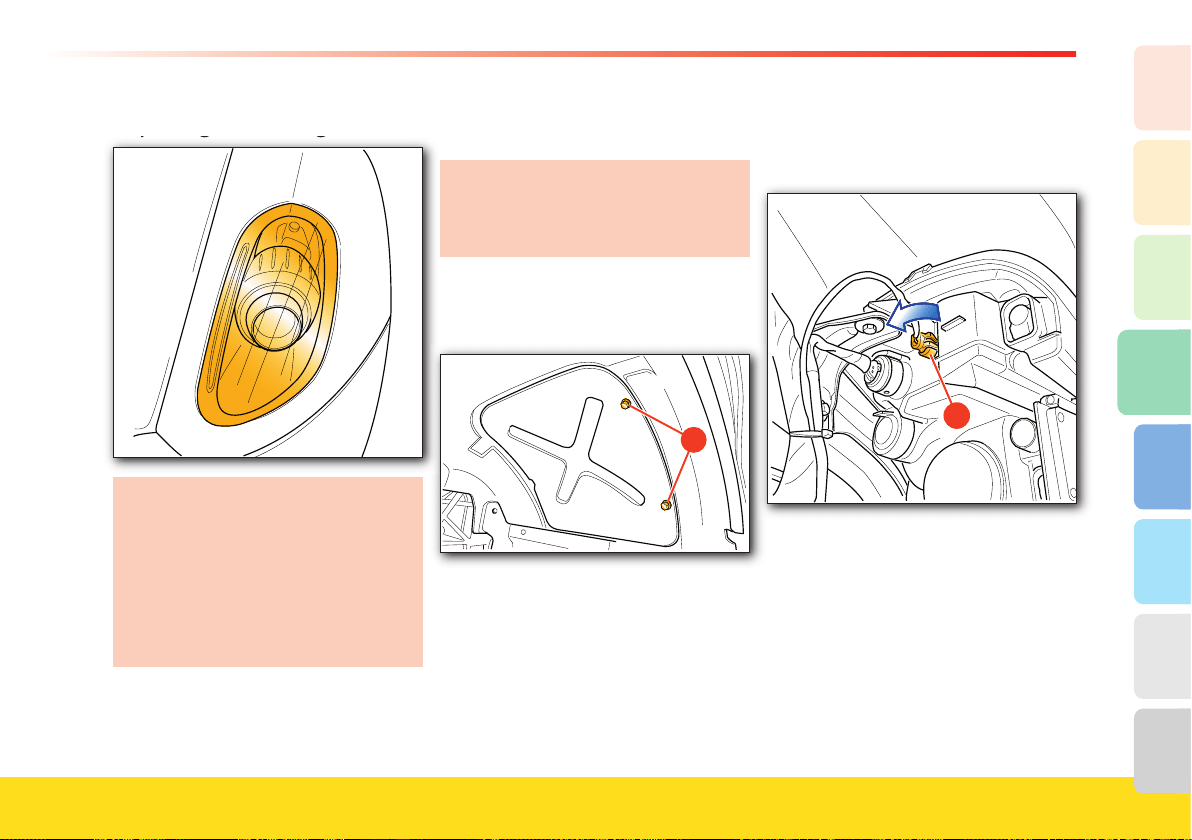
133
Advice for Emergency situations
4
2
1
3
8
7
6
5
Replacing the headlight bulbs
Replacing the headlight bulbs
The low/high beams are equipped
with bi-xenon light bulbs.
For replacement of the high and low
beam light bulbs, contact your
Authorized Ferrari Dealer
.
For aiming the headlight beam, please
contact your Authorized Ferrari
Dealer.
Replacing the front direction indicator and
position light bulbs
Before replacing a light bulb in the
headlights, always turn the ignition key
to position 0 and ensure that the
relative fuse is intact.
Turn the wheels completely inwards, then
undo the screws A and extract the panel
in the wheelhouse outwards.
�
To replace the light bulb of the front
direction indicator, proceed as follows:
• detach the connector B
�
• turn the bulb holder counterclockwise
and extract it from its seat
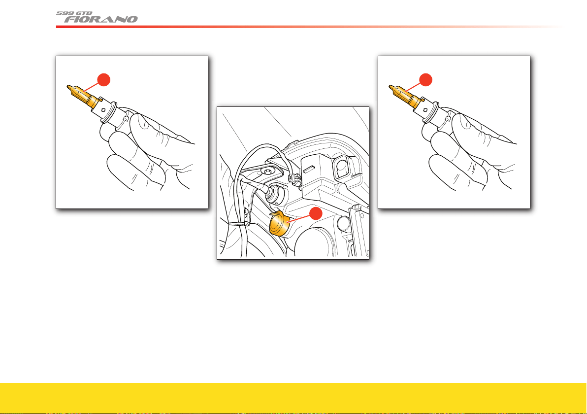
134
�
• remove the bulb C pulling it outwards
• fi t the new bulb by fully pushing it into
place
• refi t the bulb holder in its seat and turn
it clockwise until it locks
• refi t the connector.
To replace
the position light bulb,
proceed as follows:
• remove the rubber cover
D from the
headlight
�
• grip the bulb holder from its tab and
remove it from its seat
�
• replace the pressure-fi tted bulb E
• refi t the bulb holder into its seat
• refi t the rubber cover
D.
Refi t the panel into the wheelhouse.
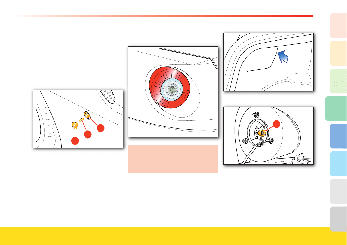
135
Advice for Emergency situations
4
2
1
3
8
7
6
5
Replacing the side direction indicator light bulbs
• Remove the transparent cover
I on the
indicator, taking care not to damage the
bodywork.
• Remove the bulb L by rotating it and
removing it from the bulb holder
M.
• Replace the bulb and refi t the
transparent cover.
Replacing the taillight bulbs
Before replacing a light bulb in the
taillights, always turn the ignition key
to position 0 and ensure that the
relative fuse is intact.
To replace a taillight bulb, proceed as
follows:
• partially remove the luggage
compartment weather strip
• remove the bulb holder B
�
• remove the bulb pulling it outward and
replace it
• refi t the bulb holder and reposition the
luggage compartment weather strip.
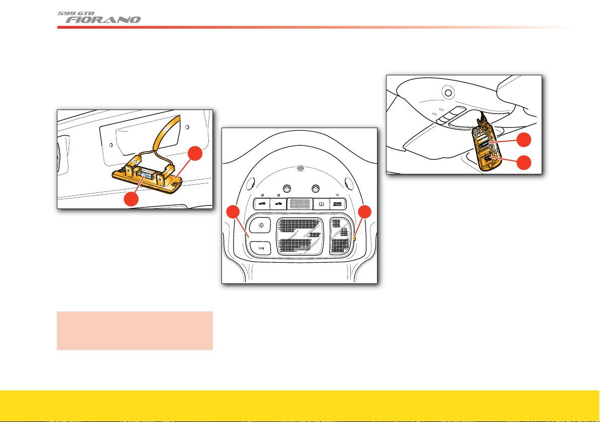
136
Replacing the license plate light bulb
To replace a license plate light bulb,
proceed as follows:
• undo the two fastening screws
• remove the transparent cover A from its
seat and replace the bulb B, which is
pressure fi tted into the two contact clips
• refi t the transparent cover and the two
fastening screws.
Replacing the auxiliary stop light and side
marker bulbs
For replacement, we recommend you
contact your Authorized Ferrari
Dealer.
Replacing other light bulbs
Roof dome light
• Gently pry out with a screwdriver at
point C to remove the dome light D
from the roof.
• Replace the light bulb involved, E or F.
• Refi t the dome light, taking care that the
cables are not crushed, inserting it fi rst
from the connector side and then
pushing on the opposite side.
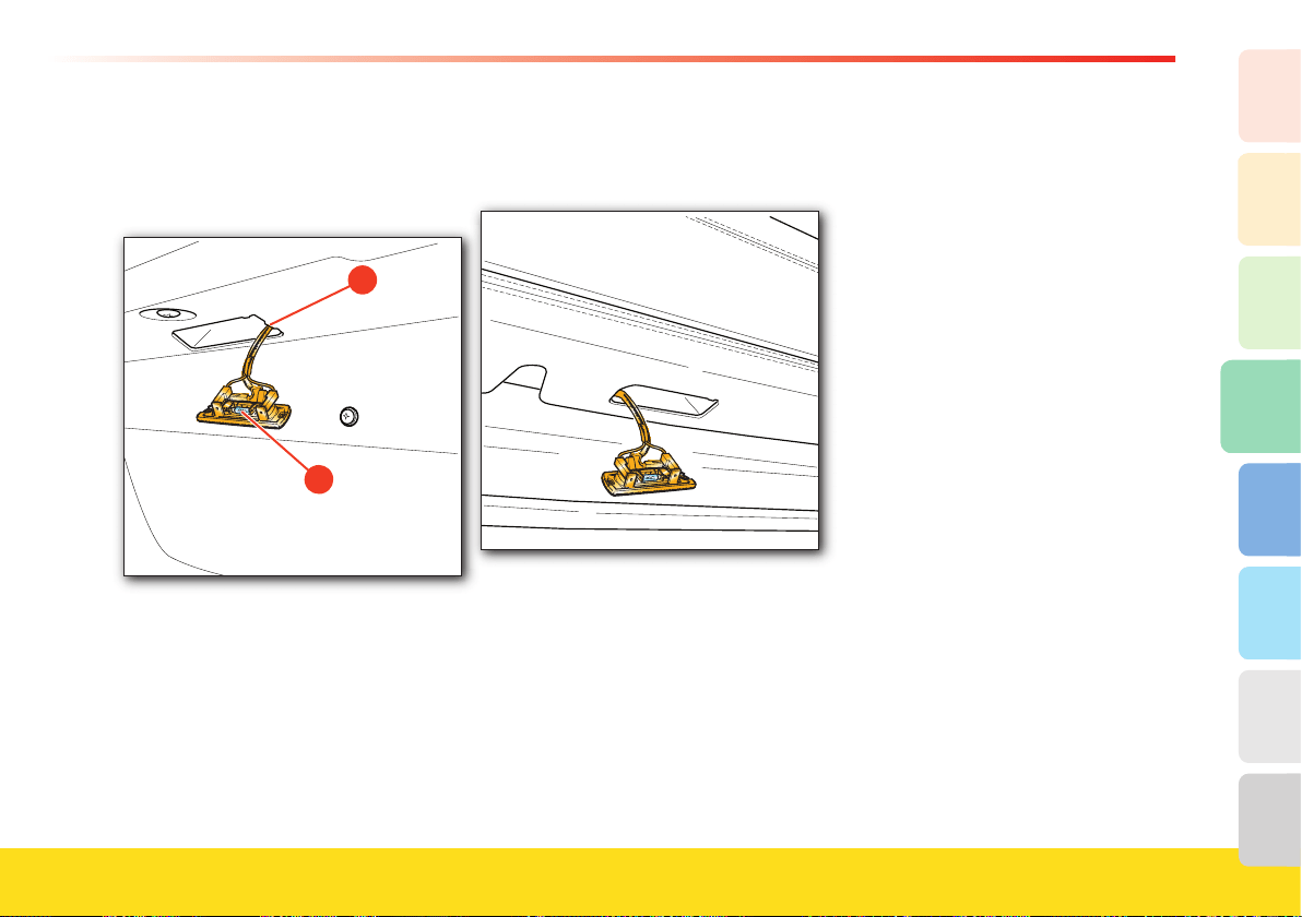
137
Advice for Emergency situations
4
2
1
3
8
7
6
5
Glove compartment light, luggage compartment
light and underdoor light
• Gently pry out with a screwdriver at
point G to slightly lift out the light.
• Remove the light from its seat.
• Remove the pressure-fi tted bulb
H.
• Replace the bulb.
• Refi t the light, taking care that the
cables are not crushed, inserting it fi rst
from the connector side and the pushing
on the opposite side.
Follow the same procedure for replacing
the underdoor light bulb and the luggage
compartment light.
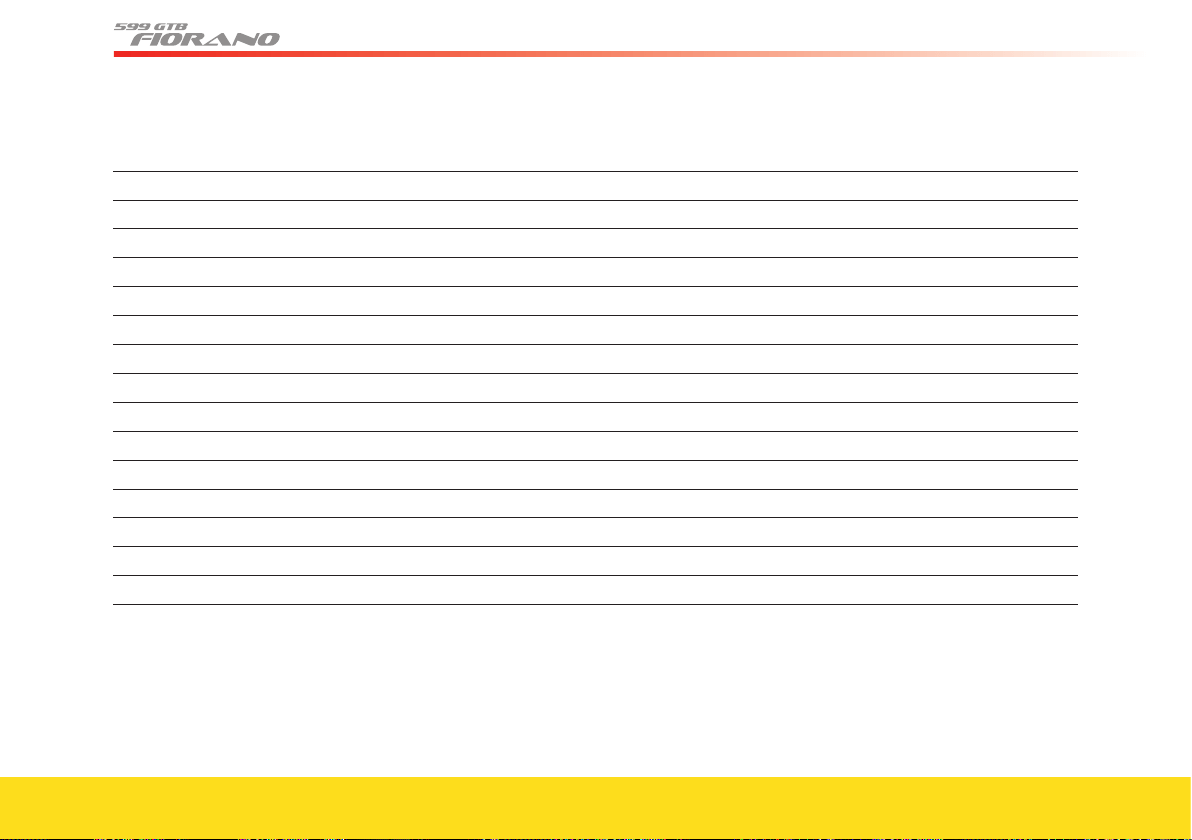
138
Light bulbs (12 V, except for low and high beams)
Type Power
Low beams and high beams Xenon (gas discharge) DAS
Front position lights
incandescent H6W
Front direction indicator lights
incandescent H21W
Side direction indicator lights
incandescent T4W
Taillights
incandescent R5W
License plate lights incandescent R5W
Auxiliary stop light LED
Rear fog lights incandescent P21W
Dome light incandescent 10W
Spot light incandescent 6W
Glove compartment light
incandescent W5W
Courtesy light incandescent W5W
Luggage compartment light incandescent W5W
Reverse gear incandescent H6W
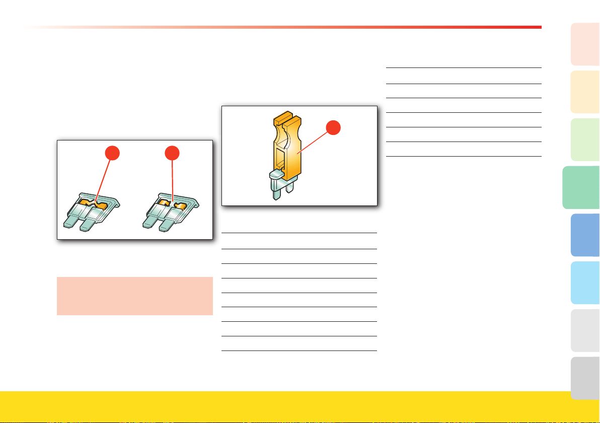
139
Advice for Emergency situations
4
2
1
3
8
7
6
5
Replacing a fuse
When an electrical device is not working,
check that the corresponding fuse is
intact.
A - Fuse intact.
B - Fuse blown.
If the problem persists, contact your
Authorized Ferrari Dealer.
When replacing a fuse, always use
fuses of the same amperage (same
colors).
The toolkit contains spare fuses.
To remove fuses, use the tweezers
C in the
fuse box in the passenger compartment
behind the small door on the dashboard,
on the left of the steering wheel.
�
Fuse colors
Ampere
dark yellow
5
brown 7.5
red 10
light blue 15
yellow
20
white 25
green 30
Maxi fuse colors
Ampere
yellow
20
green 30
orange 46
red 50
blue 60
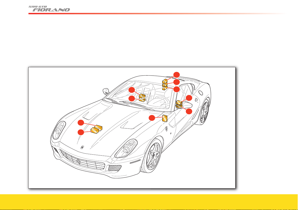
140
Location of the fuse and relay boxes
B
C
D
E
F
G
H
A
I
J
F, G, H - Fuses and relays in the luggage compartment
I, J - Fuses and relays in the passenger compartment,
passenger’s side
A, B - Fuses and relays in the engine compartment
C - Body Computer Fuses and relays
D, E - Fuses and relays in the passenger compartment,
driver’s side
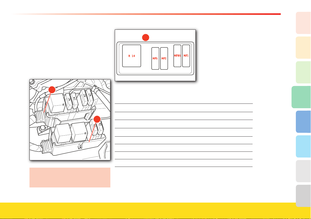
141
Advice for Emergency situations
4
2
1
3
8
7
6
5
Fuses and relays in the engine
compartment
To access these fuses you must:
• open the engine compartment
(see “Engine Compartment – Opening”
on page 69)
• remove the box covers
A and B.
We recommend that you open only the
boxes in which you need to work, to
avoid damaging other components.
�
The box A contains the following relays (R) and maxi-fuses (MF):
Ref. Amp. Use
R14 50 air pump
Ref. Amp. Use
MF5
40 +30 A.C. unit
MF2 60 +30 air pump (Link Box)
MF85
40 passenger compartment connected devices 2
MF1
40 +30 ABS (pump) (Link Box)
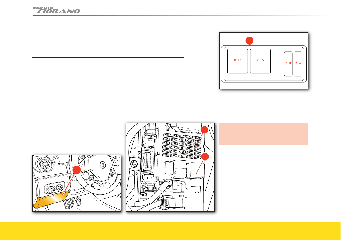
142
The box B contains the following fuses (R) and maxi-fuses (MF):
Ref. Amp. Use
R16 50 LH fans
R15 50 RH fans
Ref. Amp. Use
MF3
40 +30 RH fans (Link Box)
MF4
40 +30 LH fans (Link Box)
Body Computer fuses and relays
To access these fuses, remove the door 1
by undoing the two fastening screws.
�
�
We recommend that you open only the
boxes in which you need to work, to
avoid damaging other components.
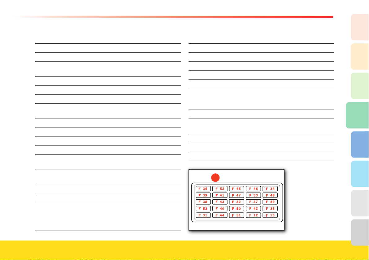
143
Advice for Emergency situations
4
2
1
3
8
7
6
5
The box C contains the following fuses (F):
Ref. Amp. Use
F36 10 +30 glove compartment motor
F52 15 driver seat heating (INT/A connected
device relay)
F45 25 (not used)
F46 15 (not used)
F34 20 (not used)
F39 10 +30 for NIM, NCL, diagnostic socket OBD,
CSA, CAV, radio/NIT, telephone option
F41 15 (not used)
F47
20 (not used)
F33 20 (not used)
F48 20 (not used)
F38 15 +30 ratio motor for luggage compartment
lock
F43 30 windshield wipers/washer
(INT/A connected device relay)
F32 10 +30 dome lights
F37
10 +15 NQS, +15 CLA (NO), third stop
F49 7.5 +15 for CSG, CSP, NIM, NCL, radio/NIT,
CEM, CRP, telephone option, dome light
panel, windshield wiper controls, steering
column adjustment
Ref. Amp. Use
F53 10 +30 rear fog light
F40 30 +30 heated rear window (INT/A relay)
F50 7.5 +15 airbag system
F42 7.5 +15 NFR
F35 7.5 +15 CLA (NC), IFR, engine signal socket,
relay coils (headlight washer, reverse gear,
high beams)
F31 7.5 INT/A for A.C. unit, NBC
F44 20 +30 cigarette lighter, passenger seat
heating (INT/A connected device relay)
F51 7.5 +15 NCR, F1 control panel
F12 15 +30 RH low beam
F13
�
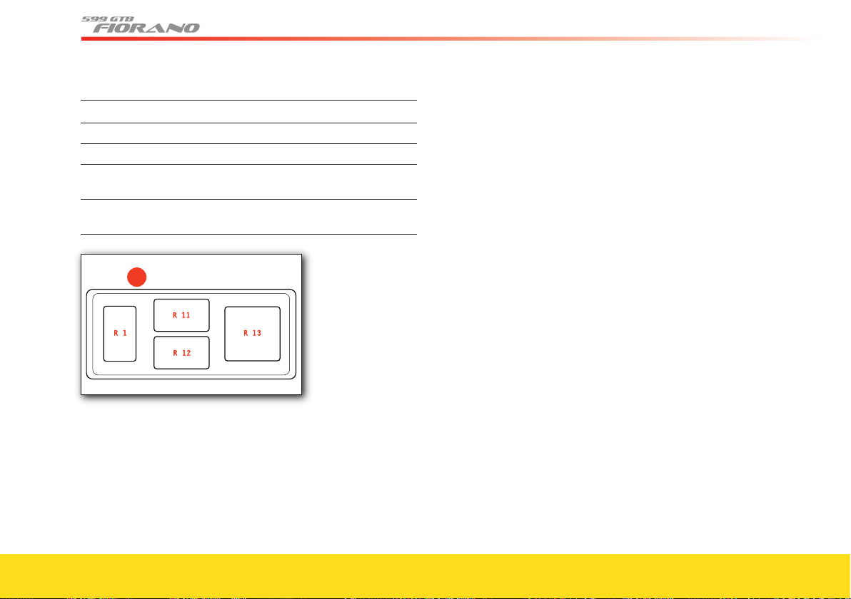
144
The box C1 contains the following relays (R):
Ref. Amp. Use
R01 20 low beams
R11 30 heated rear window
R12 30 connected devices 1 (controlled by INT/A
ignition switch)
R13 50 connected devices 2 (NBC-controlled)
(option)
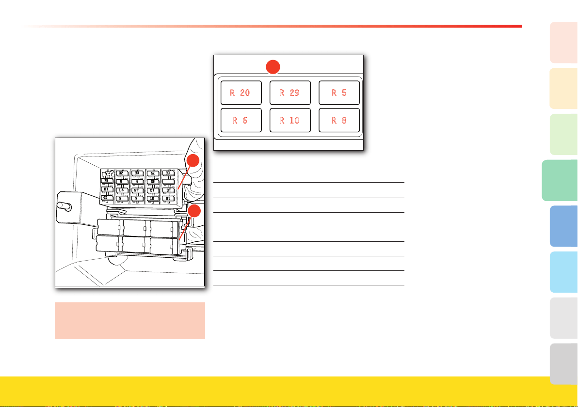
145
Advice for Emergency situations
4
2
1
3
8
7
6
5
Fuses and relays in the passenger
compartment (driver-side)
To access these fuses you must:
• lift the passenger compartment trim
panel, behind the driver’s seat.
• remove the box covers
D and E.
We recommend that you open only the
boxes in which you need to work, to
avoid damaging other components.
�
The box D contains the following relays (R):
Ref. Amp. Use
R8 20 horns
R10 20 left-hand injection
R6 20 high beams
R5 30 headlight washers
R29 20 glove compartment motor
R20 20 side marker
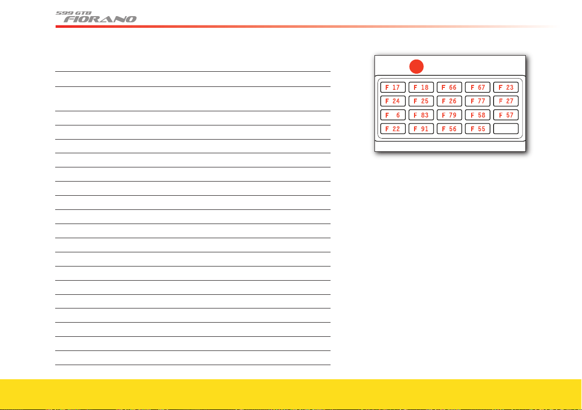
146
The box E contains the following fuses (F):
Ref. Amp. Use
F55 20 +30 steering column adjustment
(only with basic seat version)
F56 30 +30 passenger seat adjustment
F91 7.5 +30 NAP (electronics)
F22 30 LH main injection relay
F57 7.5 +15 alternator, NVO, start button
F58 5 +30 NTP
F79
5 +30 NQS
F83
30 +30 NPG power supply
F6 25 +30 from ignition switch
F27
10 +15 LH injection
F77
15 +87 LH oxygen sensor main relay
F26 15 +87 injectors main relay, LH coils
F25 10 solenoid valves, air fl ow meter, LH diagnostic pump
F24 10 +87 LH main relay
F23 7.5 +30 LH injection
F67
5 +30 front RH - rear LH side marker
F66
5 +30 front LH - rear RH side marker
F18 10 +30 RH low beam
F17 10 +30 LH low beam
�
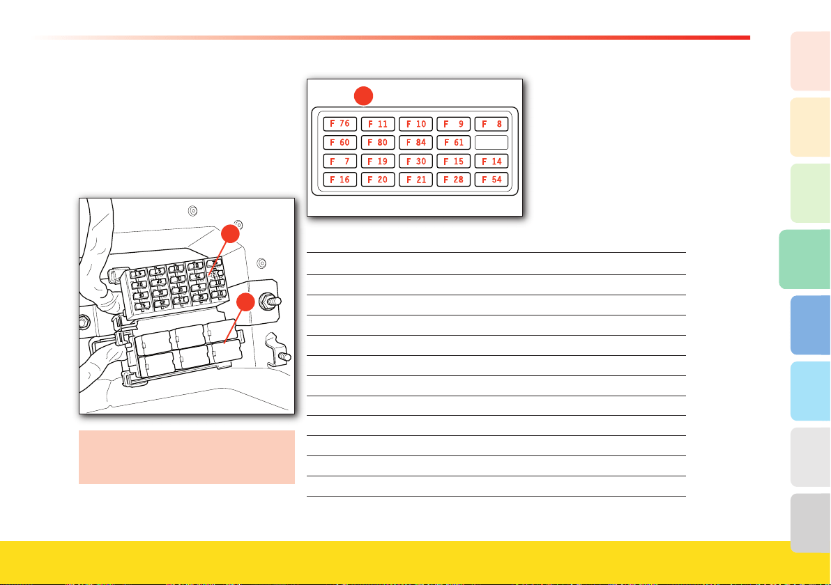
147
Advice for Emergency situations
4
2
1
3
8
7
6
5
Fuses and relays in the passenger
compartment (passenger-side)
To access these fuses you must:
• lift the passenger compartment trim
panel, behind the driver’s seat
• remove the box covers
J and I.
We recommend that you open only the
boxes in which you need to work, to
avoid damaging other components.
�
The box J contains the following fuses (F):
Ref. Amp. Use
F76
15 +87 RH oxygen sensor main relay
F11 15 +87 RH injectors main relay, coils
F10 10 +87 main relay, air fl ow meter, RH solenoid valves
F9 10 +87 RH main relay (pin F03)
F8 7.5 +30 RH injection (pin F62)
F60
20 +30 NPG, NPP door lock actuator
F80
25 +30 Hi-Fi system (bass-box and subwoofer)
F84
30 +30 NPP power supply
F61 7.5 +30 NAG (electronics)
F7 30 +30 injection main relay, RH main coil relay
F19 30 +30 starter motor
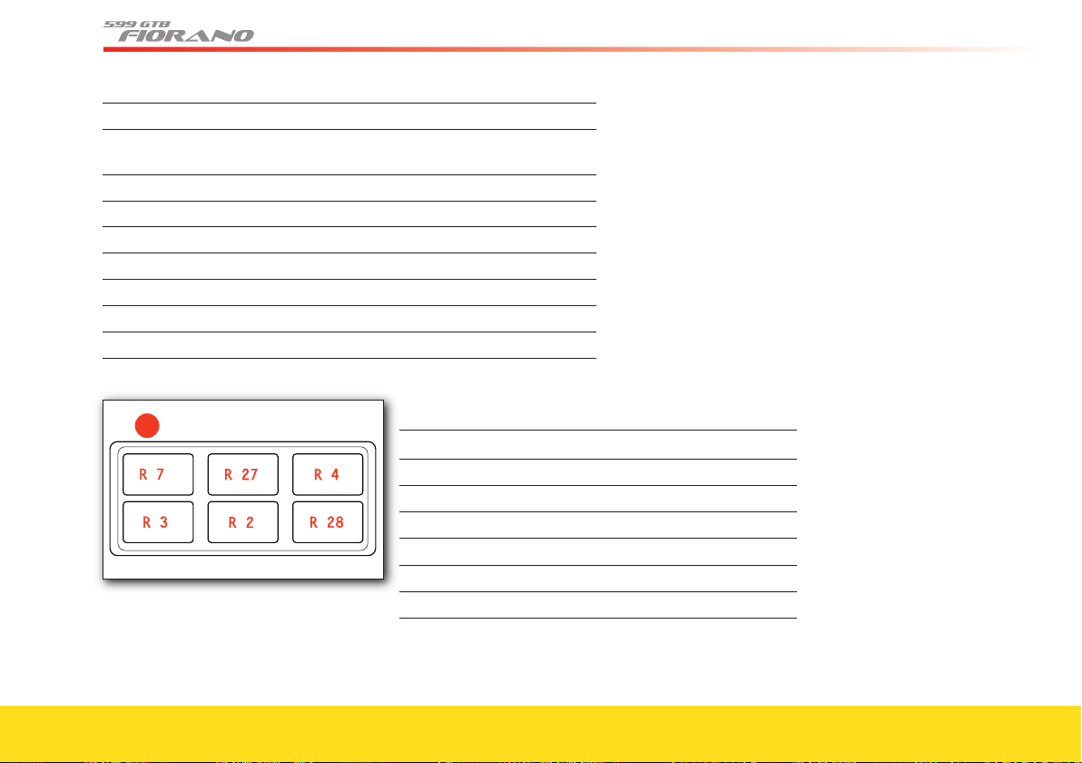
148
Ref. Amp. Use
F30 30 +30 driver seat adjustment (and steering column
adjustment, only with comfort seats)
F15 5 +15 weight sensor ECU (only for the USA)
F14 10 +15 RH injection (coils, fuel pumps relays)
F16 7.5 +30 A.C. compressor
F20 25 +30 headlight washer
F21 15 +30 horns
F28 25 +30 ABS (solenoid valves)
F54 10 +30 ABS (electronics)
�
The box I contains the following relays (R):
Ref. Amp. Use
R7 30 starter motor
R27
20 devices cut-out upon ignition
R4 20 A.C. compressor
R3 20 immobilizer
R2 20 RH main injection relay
R28 20 ignition cut-off with battery charger
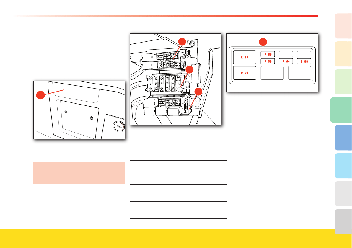
149
Advice for Emergency situations
4
2
1
3
8
7
6
5
Fuses and relays in the luggage
compartment
To access these fuses you must:
• remove the door
2 on the right-hand
side of the luggage compartment, by
undoing the two fastening screws.
�
• remove the covers on the boxes H, G
and F.
We recommend that you open only the
boxes in which you need to work, to
avoid damaging other components.
�
The box H contains the following fuses (F) and relays (R):
Ref. Amp. Use
R19 20 reverse gear
R21 20 fuel tank door
Ref. Amp. Use
F89
5 +15 NSP and NCS
F59 10 +30 fuel tank door
F64 7.5 +30 reverse gear, NSP
F88
30 +30 NCS
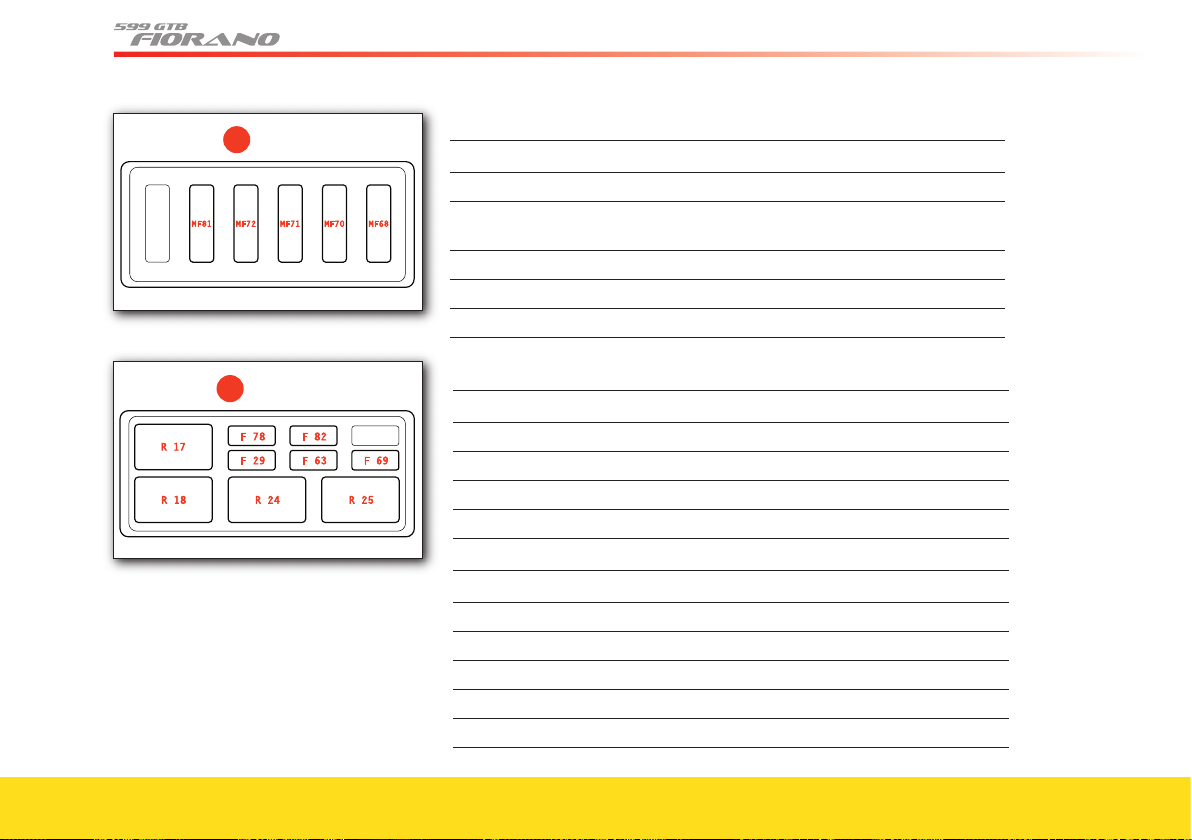
150
�
The box G contains the following maxi-fuses (MF):
Ref. Amp. Use
MF81 60 +30 passenger compartment connected devices 1
MF72
40 +30 luggage compartment connected devices
(+side marker coil relay)
MF71 60 +30 passenger compartment connected devices 3
MF70
30 +30 F1 gearbox pump
MF68
30 +30 Hi-Fi system (amplifi er)
�
The box F contains the following fuses (F) and relays (R):
Ref. Amp. Use
R17 20 1st speed fuel pump, RH bank
R18 20 2nd speed fuel pump, RH bank
R24 20 1st speed fuel pump, LH bank
R25 20 2nd speed fuel pump, LH bank
Ref. Amp. Use
F78
20 +30 LH fuel pumps
F82
5 +30 alternator sensing
F29 15 +30 battery charger
F63
20 +30 RH fuel pumps
F69
25 +30 NCR
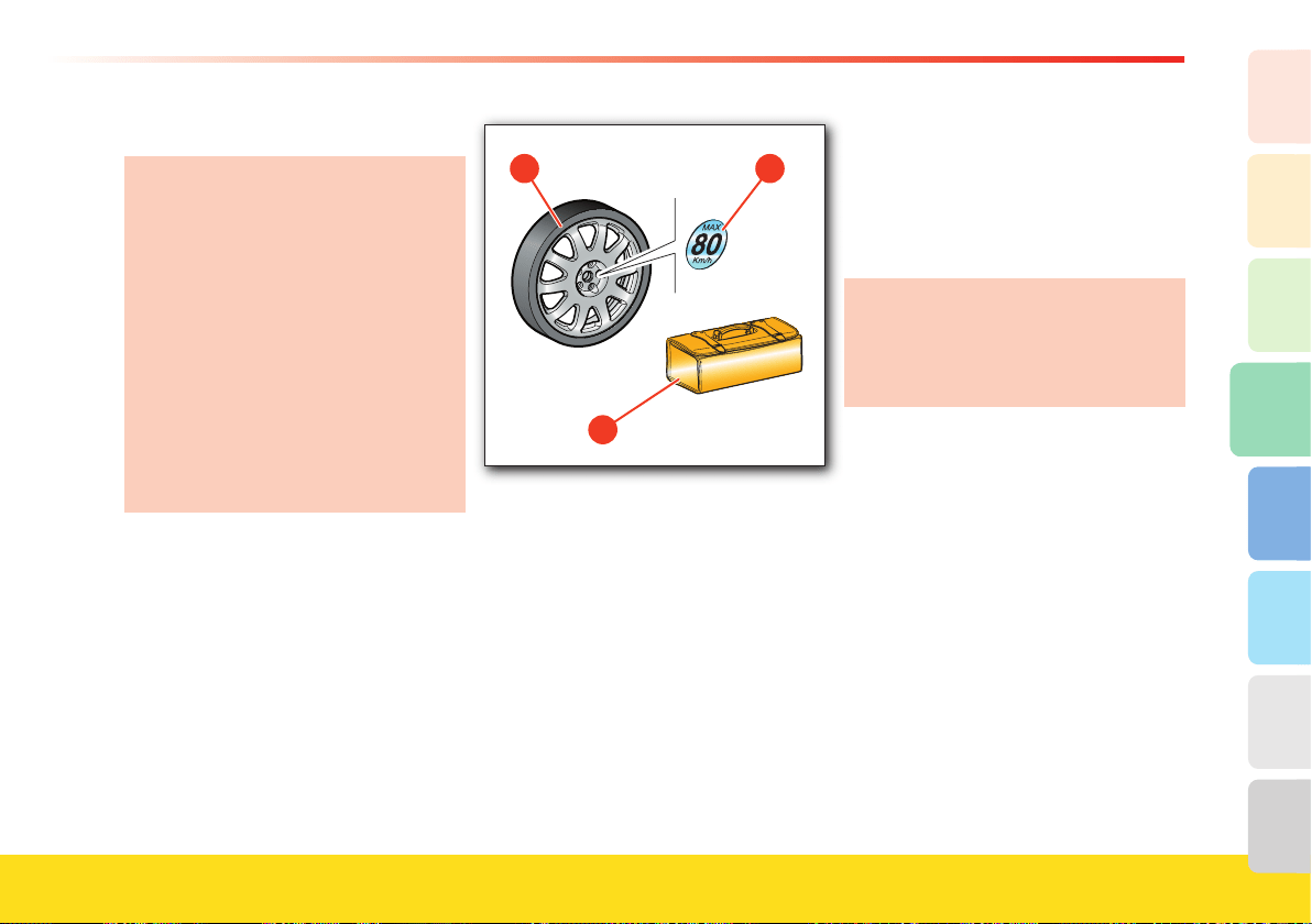
151
Advice for Emergency situations
4
2
1
3
8
7
6
5
Replacing a wheel
If one or more wheels need to be
replaced, proceed as follows:
- Replace the stud bolts with damaged
thread or cone.
- Carefully clean the stud bolts before
fi tting.
- Absolutely do not lubricate the
contact surfaces between the stud
bolt and the wheel rim, and between
the wheel rim and the brake disk.
In order not to remove the anti-lock
coating, do not clean the wheel rim
cones with solvents or aggressive
products.
Collapsible spare wheel (optional)
On request, the vehicle can come
equipped with a kit containing:
• collapsible spare wheel
A with space-
saver tire; the label B indicates the max.
speed permitted (50 mph – 80 km/h)
• additional toolkit bag
C containing: jack
and wrench to fasten the wheel stud
bolts.
Warning
• Keep the collapsible spare wheel in
proper working order, checking it at
regular intervals to ensure that the
infl ation pressure is 60,9 psi (4.2 bar).
• The spare wheel must only be used for
short trips, in emergencies.
• When the spare wheel is fi tted, never
exceed the maximum speed of (50 mph
– 80 km/h) and drive carefully,
especially around bends and when
overtaking, avoiding accelerating or
braking suddenly.
• Do not exceed the approved weight
limits.
• Do not fi t snow chains on the spare
wheel.
• Never fi t more than one spare wheel at a
time.
Failure to comply with these
instructions could lead to loss of
control of the vehicle and consequently
to damages to the vehicle and injuries
to the occupants.
Replacing a wheel
• Position the vehicle on an even surface,
then engage 1st gear and lock the rear
wheels by applying the handbrake.
• If necessary, turn on the hazard
warning lights and place the hazard
triangle at the prescribed distance.
• Take out the spare wheel and tools from
their seat in the luggage compartment.
• Loosen the fi ve wheel fastening stud
bolts by approximately one turn, using
the wrench supplied D.
• Place the base of the jack E on fl at and
fi rm ground, in position with one of the
lifting points F underneath the vehicle
fl oor.
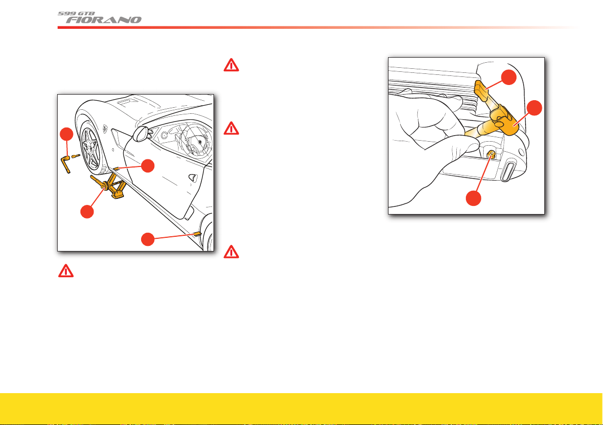
152
• Raise the vehicle carefully, using the
jack, until the wheel is lifted off the
ground.
WARNINGWARNING
If the jack is not positioned correctly,
the vehicle could slip off.
The jack supplied must only be used
for replacing the wheels.
• Completely unscrew the fi ve stud bolts
and remove the wheel.
• Fit the defl ated collapsible spare wheel
and screw in the fi ve stud bolts
tightening them snugly.
WARNINGWARNING
Infl ate the collapsible spare wheel
before lowering the car, as otherwise
the rims may be damaged
• Infl ate the collapsible spare wheel using
the infl ation kit (page 132).
WARNINGWARNING
The kit must be used in “tire infl ation”
mode.
Use lever terminal H.
• Remove the terminal H from the union
J on the cartridge and insert it in the
wheel valve.
• Lower the lever
K and start the
compressor.
• Infl ate to the indicated pressure
(see page 26 - 27).
WARNINGWARNING
The spare wheel is not equipped
with the tire pressure monitoring
sensor (see label on spare wheel
bag). After installation, it is not
monitored by the system, but it does
comply with International Regulation
ECE R64/01.
Once fi tted, we recommend you go
to the nearest Authorized Ferrari
Dealer.
• Lower the vehicle and remove the jack.
• Tighten the stud bolts completely,
moving diagonally from one to the next.
As soon as possible, tighten the stud bolts
with the torque wrench to 73.8 lb ft
(100 Nm).
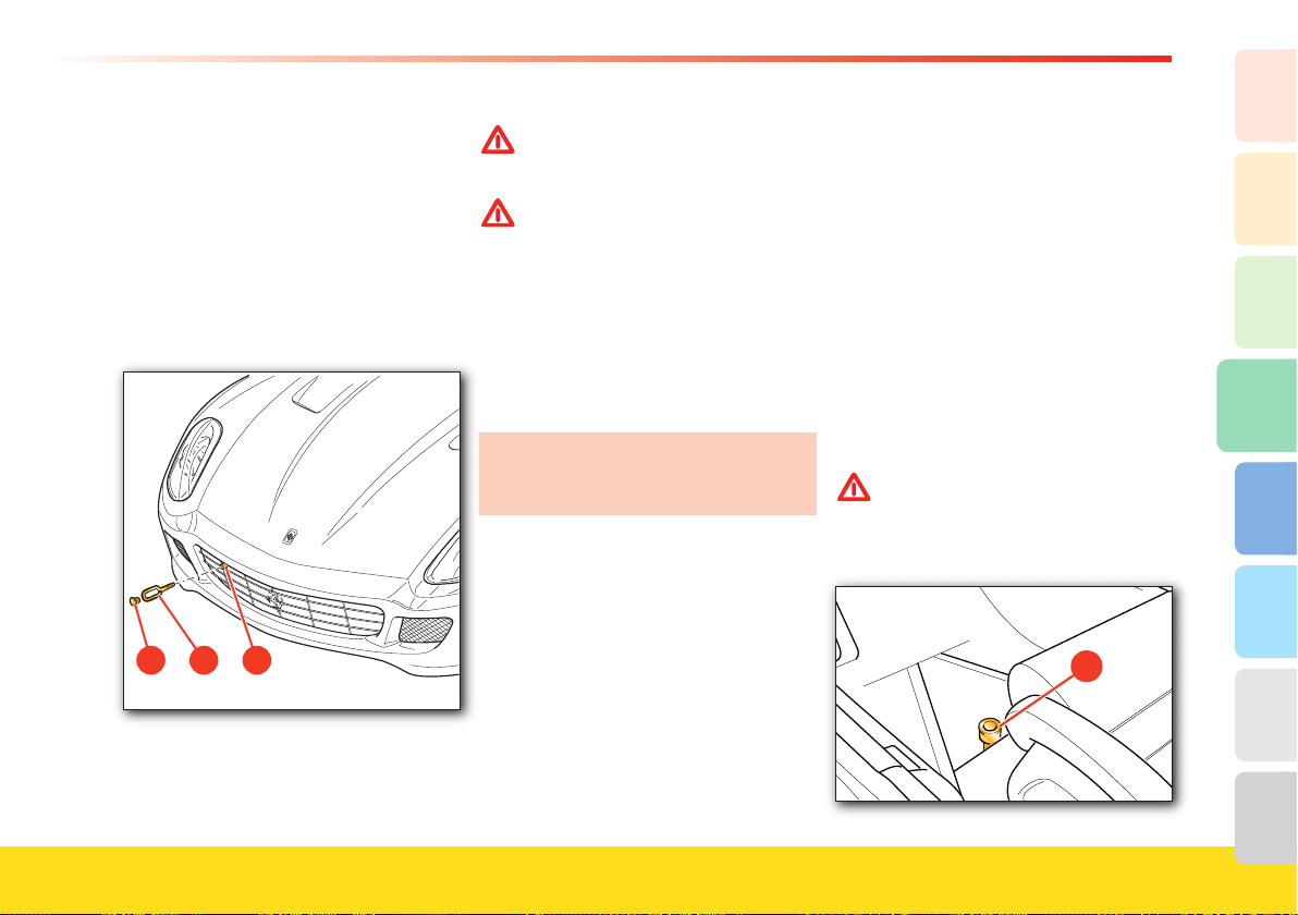
153
Advice for Emergency situations
4
2
1
3
8
7
6
5
Towing hook
When towing the vehicle, use only the
attachment point provided for the towing
hook A which must be inserted into its
seat B.
• Take the towing hook
A out of the
toolkit bag.
• Remove the cap C from its seat B.
• Screw the hook tightly into its seat
B.
C A B
•Position the gearshift lever in neutral
(“N” position for vehicles with “F1”
gearbox).
WARNINGWARNING
Always follow the applicable driving
and traffi c regulations when the
vehicle is being towed.
WARNINGWARNING
Do not tow the vehicle using a hook
attached to the suspension levers
and wheel rims, but only onto the
towing hook properly fi tted in its
seat.
Keep the ignition key in position II
to allow the lights to work and to
prevent locking of the steering wheel
in the event of steering. Do not start
the engine when towing the vehicle.
Keep in mind that the power steering
and brake servo will not be working
when the engine is off.
Fuel inertia switch
This safety switch A is located in the
passenger compartment, on the
underfl oor, in front of the driver’s seat. In
the event of a collision, it deactivates the
fuel pump relays.
Activation of this switch is indicated by
the illumination of the relative symbol on
the multi-function display (see page 86)
and by activation of the hazard warning
lights.
When the switch activates, the doors are
unlocked (if they were locked) and the
central dome lights are turned on.
WARNINGWARNING
The system can be reactivated by
pressing the button on top of the
switch.
�
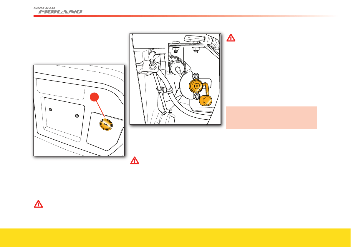
154
Battery master switch
It is located on the right-hand side of the
luggage compartment. To access it, remove
the small door B.
�
Use the battery master switch to cut off
the power supply from the battery to the
electrical system.
To disconnect the battery, move the
switch anticlockwise using a TORX T40
wrench.
WARNINGWARNING
The battery master switch must be
used only if it is not possible to
connect the battery conditioner.
Disconnecting the battery
Before disconnecting the battery,
deactivate the electronic alarm with the
remote control.
WARNINGWARNING
Never disconnect the battery from
the electrical system when the
engine is running.
Before disconnecting the battery,
lower the side windows by at least
0.78–1.18 in. (2–3 cm) to avoid
damaging the weather strips when
opening and closing the doors.
WARNINGWARNING
This operation, when the battery is
connected and fully charged, is done
automatically whenever the doors
are opened or closed. The windows
must remain lowered until the
recharged battery is reconnected. If
the battery is discharged and the
windows are fully up, only open the
doors when strictly necessary and
being extremely careful. Do not close
them again until the windows can be
lowered.
We recommend that you use the
battery conditioner if the vehicle is not
used for long periods of time.
Reconnecting the battery
Fit the TORX T40 wrench into the switch
and turn it clockwise until it stops
.
On every reconnection and before
starting the engine, proceed as follows:
- Close both the doors, and close the
luggage compartment lid. Unlock and
lock the doors using the remote control.
Open the luggage compartment lid using
the remote control.
- Set the clock (date and time on control
panel).
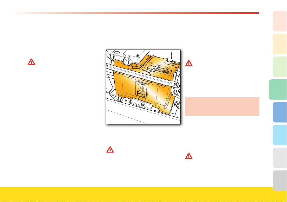
155
Advice for Emergency situations
4
2
1
3
8
7
6
5
- Close both the doors, raise the driver-
side and passenger-side windows until
they meet the upper weather strip.
Check that the windows move down to
the “upper limit” when the doors are
opened.
WARNINGWARNING
Before starting the engine, wait at
least 60 seconds with the ignition
key at position II. This allows the
electronic system that controls the
motor-driven valves and the air con-
ditioning ECU to perform their self-
learning cycles
During this time, do not to activate
any device.
The Motronic ECU’s self-learning cycle is
successful when the intake air
temperature is above 41 °F
(5 °C).
After removing the battery from the
vehicle and disconnecting it from the
system through the battery master switch,
when reconnecting make sure, before
running the self-learning cycle, that the
external air temperature is in the
indicated range.
Checking the battery
The battery is positioned on the right-
hand side of the luggage compartment.
The vehicle is equipped with a battery
with sealed energy circuit, that is
maintenance-free.
WARNINGWARNING
The battery does not need refi lling
with distilled water or sulphuric acid.
• Periodically check that the battery
terminals and posts are completely clean
and fi rmly secured.
• Visually inspect the outer casing for any
cracks.
• If the battery runs overloaded, it will
wear out quickly. Have the vehicle’s
electrical system checked if the battery
tends to discharge easily.
WARNINGWARNING
Keep the battery away from sources
of heat and do not use open fl ames
or create sparks near it.
Battery conditioner
The vehicle is equipped with a
conditioner for battery maintenance.
Using the battery conditioner
contributes to extending the life of the
battery.
This device is housed in a pocket inside
the car cover bag, provided with the vehi-
cle. The socket for connecting the battery
conditioner is found on the right-hand
side of the luggage compartment, behind
the panel B.
WARNINGWARNING
Arrange the battery conditioner in a
well visible position, away from heat
sources and children's reach.
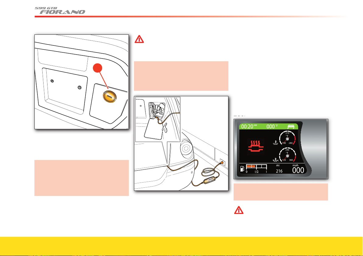
156
�
After connecting the battery conditioner
to the vehicle socket, run the connection
cable underneath the luggage compart-
ment lid, in the external/rear corner
Do not let the connection cable run
out of the vehicle, in positions other
than those indicated, to avoid
damaging the sealing gaskets and/or
the cable itself.
If you do not plan on using the vehicle for
more than a week, we advise you to con-
nect the battery conditioner in order to
preserve full battery effi ciency.
WARNINGWARNING
The vehicle cannot be started
(ignition disabled) as long as the
battery conditioner is connected to
the socket in the vehicle.
Additional and extensive technical
information on the use of the device
can be found in the manual provided
inside the pocket of the car cover bag.
Exhaust system overheating
alarm devices
In the event of irregular engine operation
and consequently high exhaust system
temperatures, the relative warning light will
be displayed on the TFT display together
with a warning message. The warning
message has two different alarm levels: high
temperatures or extreme temperatures.
The warning light display is controlled by
the thermoresistor, through the engine
ECU.
ECU.
Incorrect use of the vehicle could lead to
illumination of the TFT warning light.
WARNINGWARNING
If the temperature is high (light
fl ashing): The driver must decelerate
immediately to allow the temperature
of the exhaust system to decrease.
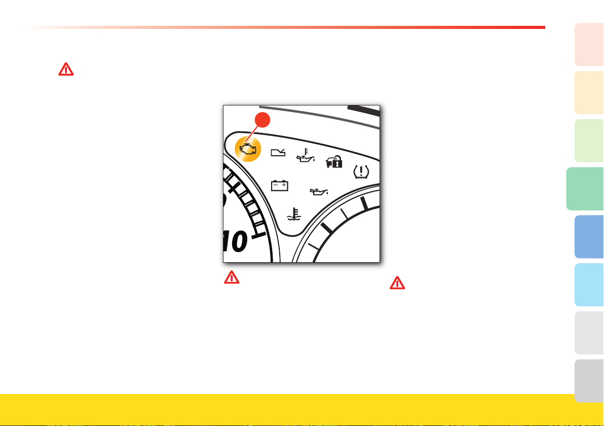
157
Advice for Emergency situations
4
2
1
3
8
7
6
5
WARNINGWARNING
If the temperature is extreme (light on
steady):
The temperature in the catalytic
converters has reached a dangerous
level and could damage them. If you
continue to drive, the engine ECU will
cut off the fuel supply to the injectors.
The driver must stop the vehicle and
turn off the engine so the exhaust
system can cool down. After about
fi ve minutes, restart the engine and
drive normally.
If the OBD warning light illuminates
(see page 157) at the same time, it is
necessary to contact an Authorized
Ferrari Dealer to check the control
unit’s memory for errors.
Ferrari is not liable for any damage
to property or personal injury arising
from failure to comply with the
warnings stated above.
Engine malfunction alarm
devices
If the “engine control system failure” A
warning light fl ashes or is permanently lit
when the engine is running, the engine or
emission control systems may be
malfunctioning.
The electronic system detects and isolates
the error, preventing damage to the
engine or the production of harmful
emissions.
�
WARNINGWARNING
When the warning light “Engine
control system failure” illuminates,
engine performance may be
considerably reduced.
Drive carefully, avoiding sudden
accelerations and high speeds.
Contact an Authorized Ferrari
Dealer immediately.
Replacing the brake pads and
brake discs
Brake pads
The brake pads are equipped with a wear
sensor, connected to the brake warning
light. When this warning light comes on
or, whenever braking no longer appears to
be regular, the pad thickness and the
condition of the braking surfaces must be
checked.
The minimum thickness allowed for the
pads is 0.12 in./3 mm (thickness of the
friction material only).
Pad replacement
The brake failure warning light will
illuminate to indicate excessive wear of
the brake pads, which must be replaced
immediately.
WARNINGWARNING
In order to help ensure the quality of
the components and accurate
installation, we recommend that you
have the procedure performed by your
Authorized Ferrari Dealer.
To help ensure proper breaking-in of
the pads following replacement, avoid
sudden and sharp braking until the
new pads have been run-in, after
about 186 mi (300 km).

1. General
2. Safety
3. About your Vehicle
4. Advice for Emergency Situations
5. Care of the Vehicle
6. Table of Notes
7. Glossary
8. Index
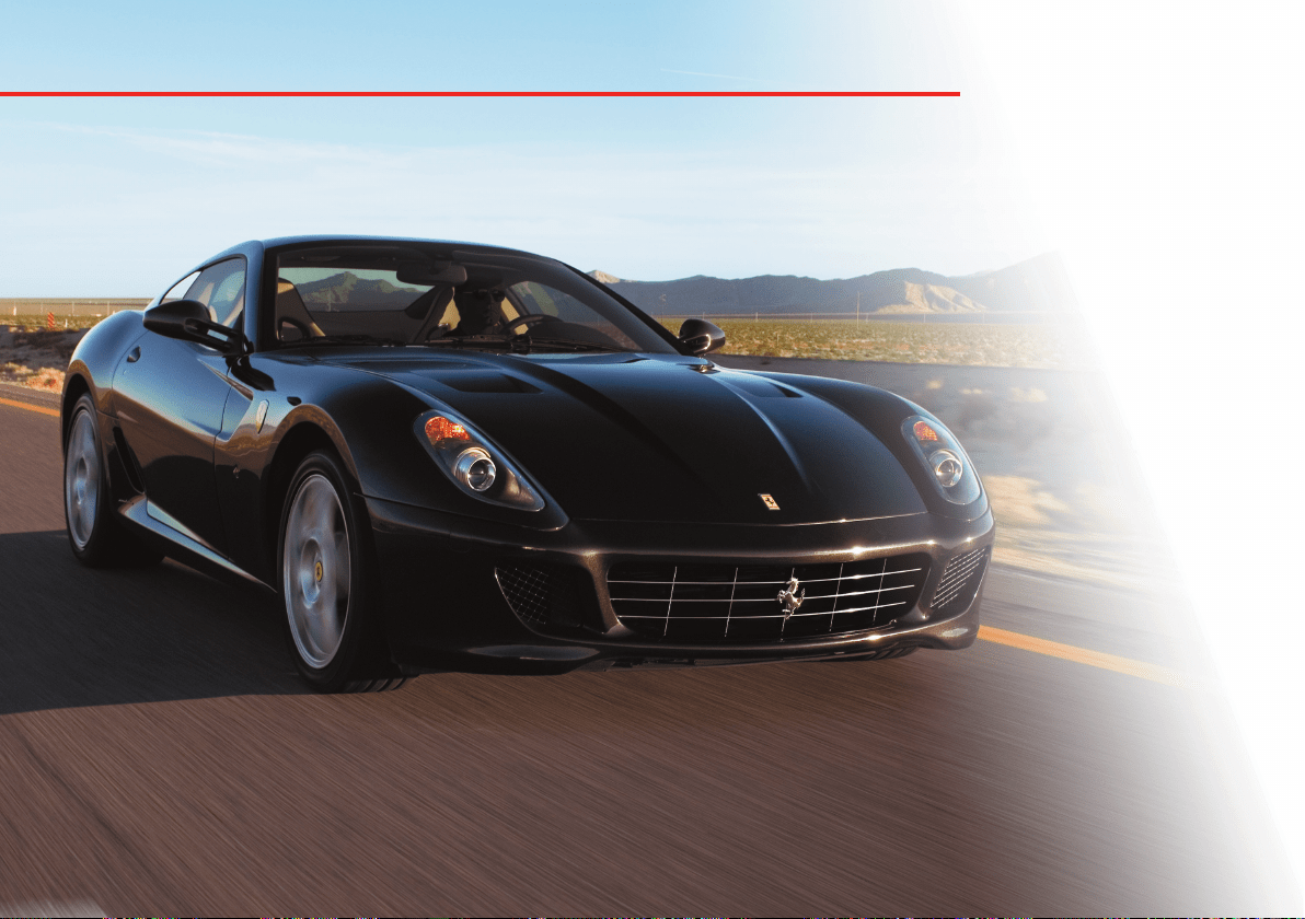
Warranty and Service Book
Maintenance
Level checks
Wheels and tires
Care of the seat belts
and pretensioners
Cleaning the vehicle
If the vehicle is stored
for long periods

160
Warranty and Service Book
The vehicle comes equipped with a
“Warranty and Service Book”.
This contains the vehicle’s warranty
validity conditions.
WARNINGWARNING
The Warranty and Service Book also
contains special blank spaces where
the Authorized Ferrari Dealer can
register the regular maintenance
services performed, as indicated in
the maintenance schedule.
Maintenance
It is essential to always keep the vehicle in
proper working order to ensure a long
working life and to prevent any running
defects, caused by negligence or lack of
maintenance, and consequently to avoid
hazardous situations.
All repair work on any component of
the safety system must be performed
by the Authorized Ferrari Dealer
.
Maintenance schedule
All the maintenance and checks indicated
in the “Warranty and Service Book” must
be performed at an Authorized Ferrari
Dealer at the prescribed intervals.
It is however advisable to immediately
report to your Authorized Ferrari Dealer
any small fault which may occur during
use of the vehicle (e.g., small fluid leaks)
and not to wait until the next service is
due to correct the problem.
It is required to have the periodic
maintenance services performed at least
once a year, even if the specified mileage
limit has not been reached (see
“Maintenance Schedule” in the “Warranty
and Service Book”).
Chassis and bodywork maintenance
The vehicle chassis is entirely made of
aluminium, and has been designed using
the technology referred to as “
Space
Frame”.
The chassis therefore has technological
and manufacturing specifications that
require that any operation be performed
by staff specially trained to work with this
innovative technology.
It is of crucial importance to use
equipment tested by Ferrari if the repair
work is to be performed in accordance
with rules of good workmanship. Proper
execution of repair work ensures that the
commercial value of the vehicle is
preserved and the safety standards are
complied with.
If the chassis is damaged as a result of
an accident, Ferrari recommends that
you contact your Authorized Ferrari
Dealer
We recommend that you use original
genuine Ferrari parts, which can be
obtained from your Authorized Ferrari
Dealers.
The chassis, under standard conditions of
use, requires no maintenance; it is
however advisable to contact your
Authorized Ferrari Dealers. at the
intervals indicated in the “Warranty and
Service Book” in order to have it checked.
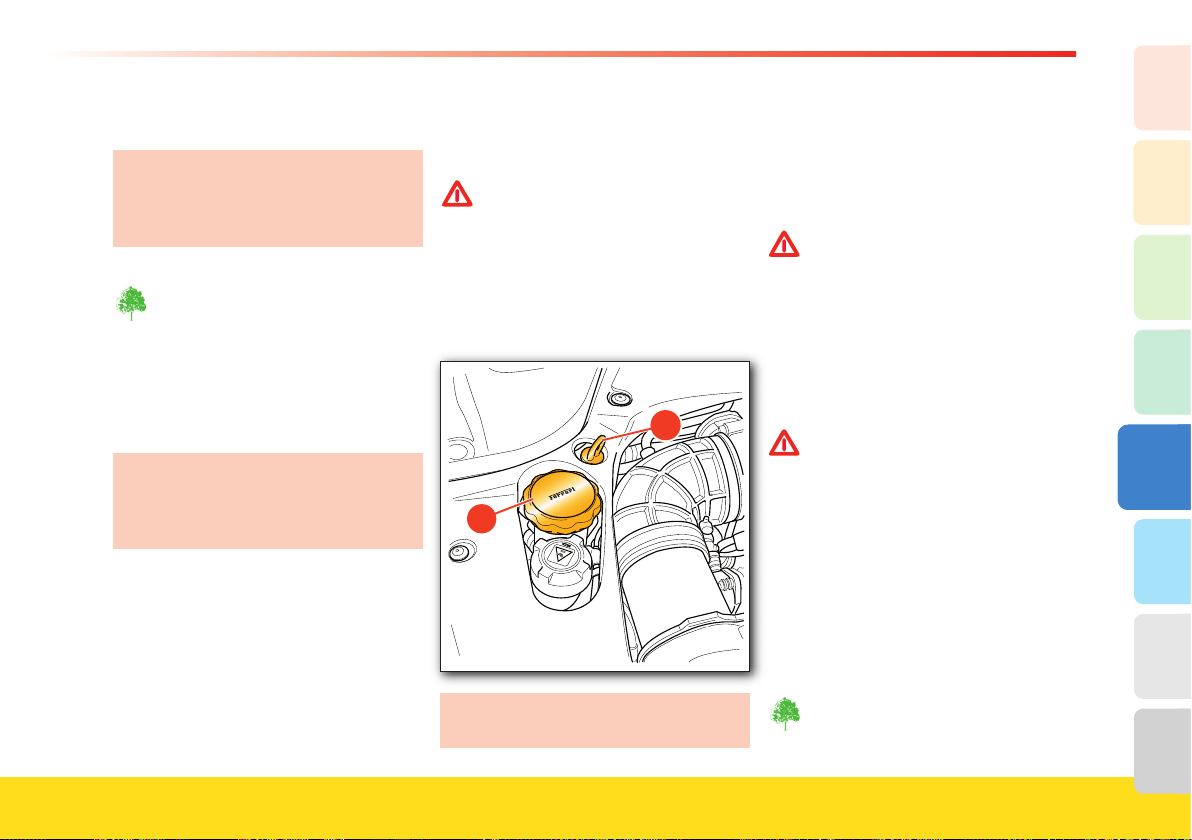
161
Care of the Vehicle
5
2
1
3
8
7
6
4
Level checks
The level checks must be performed at
the intervals indicated in the “Warranty
and Service Book” or, in any case,
before starting a long journey.
All the materials used for the
following operations (e.g, cloths
soaked with oil or grease, pans, etc.)
must be disposed of in compliance
with local environmental protection
regulations.
Open the engine compartment lid.
We recommend that you use only
lubricants and/or fl uids recommended
by
Ferrari (see the “Recommended
lubricants and fl uids” table).
Engine oil
Proceed as follows:
A Run the engine at idle until reaching an
engine oil temperature ranging from 185 to
194°F (85 - 90°C).
B Run the engine at 4500 RPM for 1 minute.
C Run the engine at idle for 2 minutes, then
(without turning the engine off) check the
oil level.
WARNINGWARNING
If the oil level is not checked within 3
minutes (instead of 2 minutes, as indicat-
ed above), repeat steps B and C before
checking the level.
D Remove the dipstick 1 from the sump and
check the level: this must be between the
MIN and MAX notches on the dipstick.
1.4 bar
A878
Difference between MAX and MIN = 0.4
US Gallon (1.5 liters).
E If the oil level is too low, unscrew the cap 2
on the tank and top up with the
recommended oil. Keep the oil level
between the MIN and MAX notches. Screw
the cap
2 back on tightly.
WARNINGWARNING
If the oil level is below the “MIN”
notch, top it up and then have the
system checked by your Authorized
Ferrari Dealer.
F Run the engine at 4500 RPM for 1 minute.
G Run the engine at idle for 2 minutes, then
(without turning the engine off) check the
oil level.
WARNINGWARNING
As the fi rst check was performed within
a time range of 2-3 minutes, the second
oil check must also be performed within
the same time range.
For instance, if the fi rst check was per-
formed after 2 min. and 30 sec., the sec-
ond check must also be performed after
approximately 2 min. and 30 sec..
H Remove the dipstick 1 from the sump and
check the level: this must be between the
MIN and MAX notches on the dipstick.
Screw the cap
2 back on tightly.
Top up the oil with care to avoid
spilling it from the fi ller neck.
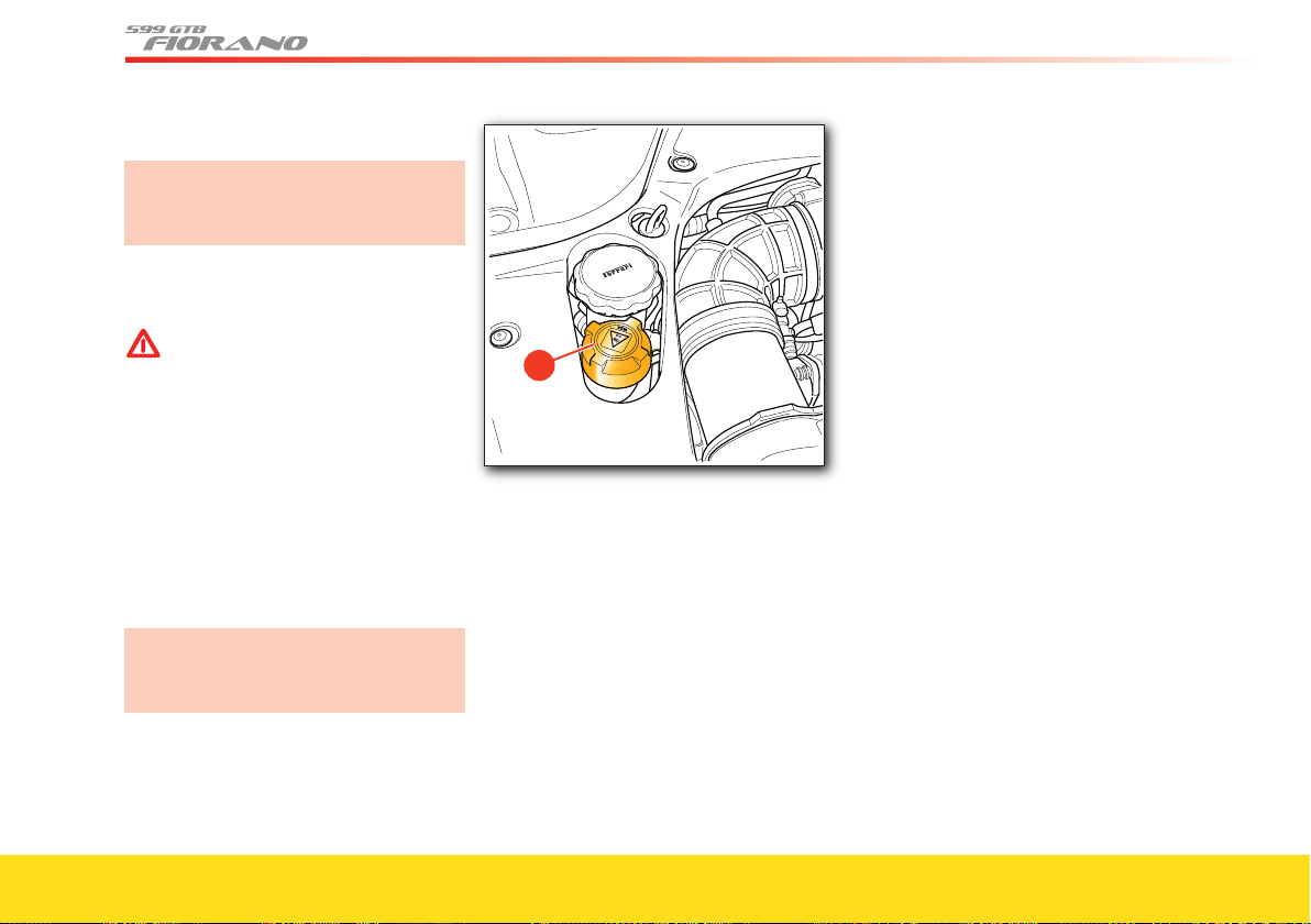
162
Gearbox and F1 gearbox system oil
We recommend that you have the oil
level checked by your Authorized
Ferrari Dealer or by skilled staff.
Coolant
WARNINGWARNING
This procedure must always be
performed when the engine is cold.
Never remove the cap C from the
expansion tank when the engine is
running or hot.
• Remove the cap C from the expansion
tank in the engine compartment and
check that the level is at approximately
1.57 in. (40 mm) from the top of the
fi ller neck.
• If the level is low, fi ll it up with the
recommended fl uid.
If frequent refi lls are required after
short trips, have the system checked by
your Authorized Ferrari Dealer.
• Screw the cap C back on tightly.
1.4 bar
A878
�
Filling the circuit
To fi ll the circuit (this operation must be
performed when the engine is cold),
proceed as follows:
• Detach the bleeder pipe on the radiator
and hold it lifted, so that it is at the
same height as the fi ller neck, in order
to prevent spilling.
• Turn key to position II and select the
maximum temperature on the air
conditioning and heating system.
• Completely unscrew the bleeder cap on
the heater inlet pipe.
• Slowly pour in the indicated quantity of
coolant through the expansion tank fi ller
neck, until the fl uid comes out from the
open bleeder on the radiator. Reconnect
the radiator bleeder pipe and complete
the fi lling procedure until reaching the
Max. level. If water comes out of the
heater pipe, close the cap.
• Close the bleeder cap on the heater
pipe.
• Close the fi ller neck cap.
• Turn on the heater by selecting the
Max.
temperature for the air conditioning and
heating system.
• Start the engine and let it idle.
• Slowly open the fi ller cap and top up
until the fl uid is visible in the fi ller neck
and until the radiator cooling fan
activates.
• Check that all the vents are blowing hot
air, at the same temperature ~ 122° F
(~50 °C).
• After the coolant level in the fi ller neck
has stabilized, close the fi ller cap.
• Run the engine until it reaches 3000
RPM, wait one minute and then let it
idle.
• Run the engine until it reaches
3000 RPM, turn off the heater and, after
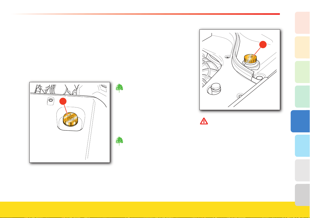
163
Care of the Vehicle
5
2
1
3
8
7
6
4
one minute, bring it back to idle.
• Stop the engine and let it cool down.
• Check the level once again and, if
necessary, fi ll up as indicated above
(without bleeding).
• Screw on the fi ller neck cap tightly.
Hydraulic steering system oil
�
The level check must be performed with
the engine warm, after having driven at
least 9 miles (15 km), and with the
vehicle parked on fl at ground.
Remove the cap
D from the tank in the
engine compartment and check that the
level is between the
MIN and MAX
notches on the dipstick.
The oil level must be checked with the
cap resting on the tank.
Fill up if necessary with the
recommended oil up to the MAX
level.
Screw the cap D back on tightly.
Never dispose of used fl uid in the
environment.
Brake/clutch oil
• Check that the fl uid in the tank is near
the MAX level.
• If the level is low, unscrew the cap
E and
fi ll up with the recommended oil, taken
from a sealed container.
Never dispose of used fl uid in the
environment.
�
WARNINGWARNING
The oil contained in the brake and
clutch systems, in addition to
damaging plastic, rubber and
painted parts, is highly dangerous if
it comes into contact with the eyes
or the skin.
In case of contact, wash the affected
part thoroughly with running water.
To avoid any risk, always use
protective goggles and gloves.
Keep out of children’s reach!
On vehicles equipped with “F1” gearbox,
the tank supplies the braking system only.

164
The symbol on the tank cap indicates that
the system contains synthetic fl uid.
WARNINGWARNING
The use of mineral-based fl uids will
irreparably damage the system
rubber gaskets.
Do not use fl uids other than those
already contained in the system for
refi lls.
• When the system has been refi lled,
screw the cap back on.
Windshield washer fl uid
The tank for the windshield wipers and
washer fl uid can be accessed by lifting the
engine compartment lid.
• Lift the cap F and fi ll the tank with the
recommended fl uid (see the
“Recommended Lubricants and Fluids”
table on page 30) until it can be seen in
the fi lling manifold.
• Close the cap.
�
Wheels and tires
To help ensure performance, endurance
and the best tire adjustment on the wheel,
it is important to comply with the
following instructions for the fi rst 124–
186 mi. (200–300 km) with new tires:
• avoid sudden accelerations
• avoid sharp braking and steering
• drive at moderate speed on straight
roads and on curves.
How to use the tires
This is a high performance vehicle. The
wear of the tires will depend
signifi cantly on your driving habits and
patterns.The tires must be constantly
kept in good condition help ensure
safe driving. Check regularly for wear
and damage.
The infl ation pressure must correspond to
the specifi ed values and must be checked
only when the tires are cold. Tire pressure
increases as the tire temperature
progressively increases.
Never reduce the pressure if the tires are
hot.
Insuffi cient tire pressure can lead to
overheating, damage and even destruction
of the tires.
WARNINGWARNING
Infl ating the tires to a pressure
differing from that prescribed (see
table on page 26 - 27) will render
the monitoring system ineffi cient.
Periodically check the tire pressure.
165
Care of the Vehicle
5
2
1
3
8
7
6
4
Sudden impacts against sidewalks, holes in
the road and other obstacles of various types,
as well as long trips on rough roads, can
cause damage to the tires that may not
always be visible.
Check the tires regularly for any signs of
damage (e.g., scratches, cuts, cracks, bulges,
etc.).
If sharp objects penetrate the tires, they can
cause damage which is only visible when the
tire is removed.
Have any damage inspected by a qualified
technician as it may considerably reduce tire
life.
Remember that tires deteriorate over time,
even if they are rarely used or not used at all.
Cracks in the tread and side walls, possibly
accompanied by bulging, are sure signs of
aging.
Wheel with REVERSE RIM (HGTE
package).
The tire must be fitted and removed
from the inner part of the rim only
to avoid damaging the rim and
pressure sensor!
This operation must be performed
by skilled staff.
Contact your Authorized Ferrari
Dealer.
Your Authorized Ferrari Dealer have
the necessary equipment for tire
replacement.
Have the tires replaced by your
Authorized Ferrari Dealer
, who has
the required tools and equipment in
order to avoid that improper or
careless operations damage the sensor
inside the wheel.
Your Authorized Ferrari Dealer can
certify whether aged tires are suitable
for use. In any case, tires that have
remained on a vehicle for more than
3 years must be checked by an
Authorized Ferrari Dealer.
WARNINGWARNING
We recommend that you replace the
tires when worn to a depth of less
than 0.067 in (1.7 mm), but in no
case should they be kept on the
vehicle for more than four years,
even if sufficient tire tread remains.
Frequent use in maximum load
conditions and at high temperatures
may accelerate aging.
Never fit tires of uncertain origin.
WARNINGWARNING
The tires are of the “directional” type
and there is an arrow marked on
their side to indicate the direction in
which they must rotate or which side
is the outer side. In the case of
replacement, the best performance
levels can only be provided if the
rotation direction corresponds with
the direction indicated by the arrow.
Tires on the same axle must always
be replaced in pairs.
Regularly check the tire tread (minimum
acceptable depth 0.067 in (1.7 mm). As
the tread wear increases, there is a greater
risk of skidding.
WARNINGWARNING
Drive carefully on wet roads to
reduce the risk of “aquaplaning”.
Wheel alignment check and adjustment
When you notice unusual wear of the tires
and, in any case, at the intervals
prescribed in the “Warranty and Service
Book”, have your Authorized Ferrari
Dealer check the wheel alignment.
166
Maintenance of the seat belts
and pretensioners
• Periodically check that the screws on the
anchoring points are tight and that the
seat belt is in proper condition and slide
smoothly.
• The seat belt must be kept clean; the
presence of any dirt could jeopardize
the efficiency of the seat belt retractor.
• To clean the seat belt, wash it by hand
with mild soap and water and let it dry.
Do not use strong detergents, bleach or
aggressive solvents, as they can weaken
the fibers.
• Do not let the seat belt retractors get
wet: they will function properly only if
they are kept dry.
• The pretensioner requires no
maintenance or lubrication. If immersed
in water or mud, the pretensioner must
be replaced.
• The pretensioner must be replaced at
the intervals indicated in the “Warranty
and Service Book”.
WARNINGWARNING
All work on any part of the safety
system components may only and
exclusively be performed by an
Authorized Ferrari Dealer
.
Cleaning the vehicle
Cleaning the exterior
All the materials used for the
following operations (e.g., cloths
soaked with oil or grease, pans, etc.)
must be disposed of in compliance
with the environmental protection
regulations.
Proper care of the vehicle on the part of
the owner is essential for the vehicle long
life.
Below is a list of the main precautions to
be taken.
• Certain parts of the vehicle should not be
left wet or dirty for long periods of time:
in particular, the passenger compartment
floor and the luggage compartment must
always be kept clean and dry. The
draining holes under the doors should be
kept unclogged to allow any water to
drain.
• The underbody and the lower surfaces of
the vehicle should be cleaned regularly,
and more frequently (at least once a
week) if the vehicle is used on salty or
rough roads. The vehicle should be
cleaned thoroughly and carefully:
cleaning that only wets the vehicle,
without removing dirt or mud completely
can damage the bodywork.
• The vehicle must be washed regularly
with suitable equipment. Do not use
very hot water or steam to clean the
paintwork and the lower surfaces. It is
advisable to soften any dirt first, then
remove it with a jet of water at room
temperature.
WARNINGWARNING
Do not use aggressive substances to
clean the windows. Using aggressive
substances may damage some parts
of the body.
• Do not wash the vehicle in direct
sunlight or when the bodywork is still
warm: ensure that the jet of water does
not hit the paintwork too hard. Wash the
vehicle with a sponge and a solution of
mild soap and water. Rinse the vehicle
again with a jet of water and dry it with
a piece of chamois leather.
WARNINGWARNING
When the vehicle has been washed,
apply slight pressure to the brake
pedal at moderate speed before
driving at a normal speed, until the
brake discs and pads have cleaned off.
In order to maintain the shine of the
paintwork, polish it once or twice a year
with the products recommended by Ferrari
.

167
Care of the Vehicle
5
2
1
3
8
7
6
4
• Any areas that are cracked or chipped as
a result of stones, scratches or parking
maneuvers, etc., must be immediately
repaired by an Authorized Ferrari
Dealer.
• Do not park the vehicle in damp and/or
unventilated areas for long periods of
time.
Carbon parts
Have small scratches and marks on the
carbon structure removed by an
Authorized Ferrari Dealer only.
Improper operations may irreparably
damage the carbon parts.
Do not use aggressive organic substances,
such as: gasoline, kerosene, petroleum,
acetone or solvents.
Cleaning and care of the leather upholstery
As indicated in the “MAINTENANCE
SCHEDULE” (see “Warranty and Service
Book”), proper and regular treatment, at
least once a year, will help preserve the
quality, natural characteristics and softness
of the leather upholstery in your
Ferrari.
With this in mind, specific leather care
products are also available (“cleaner” and
“cream”) both tested by
Ferrari.
These products can be ordered through
the Ferrari Spare Parts Department,
both individually and as part of the “Care
Kit” which includes the complete range of
products for cleaning the vehicle.
For use of the “Care Kit” products,
contact your Authorized Ferrari
Dealer.
The following products must be avoided
when cleaning the leather: harsh
detergents, turpentine, liquid stain
removers, benzene, solvents and domestic
cleaning products. All of these products
damage the natural material.
If the vehicle is stored for long
periods
If the vehicle is not used for long periods
of time, it is advisable to take certain
precautions:
• if possible, park the vehicle on a level
surface, in a covered and well-ventilated
area
• keep the vehicle stationary by engaging
a gear and do not use the handbrake
• bring the tire pressure to 43.5 psi
(3.0 bar) and periodically change the
tire resting point on the ground
• disconnect the battery from the system
If you do not wish to disconnect the
battery in order to keep certain devices
functioning, such as the alarm system,
etc., the battery must be recharged at
least once a month. If the vehicle is not
used for long periods of time with the
battery disconnected, the battery must
be recharged at least every three
months.
• protect the vehicle with a breathable
fabric cover, avoiding materials that
would prevent any dampness on the
bodywork from evaporating.
Before using the vehicle again after long
periods of inactivity, adjust the tire
pressure to the indicated pressure and
check the fluid levels of all the systems.

1. General
2. Safety
3. About your Vehicle
4. Advice for Emergency Situations
5. Care of the Vehicle
6. Table of Notes
7. Glossary
8. Index

Warning notes
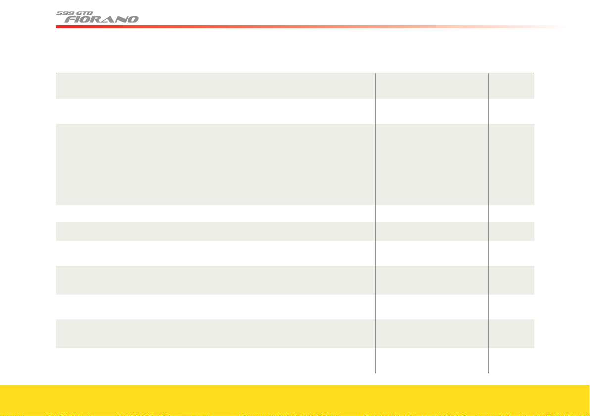
170
Extreme caution required Subject Page ref.
Because of the high power generated by the engine, we recommend that the vehicle only be
used by experienced drivers.
Introduction
Page 4
The vehicle is equipped with emission control and monitoring systems, which must always
function properly.
Introduction
Page 7
Engine exhaust, some of its constituents, and certain vehicle components contain or emit
chemicals known to the State of California (CA) to cause cancer and birth defects and
reproductive harm. In addition, certain fluids contained in vehicles and certain products of
component wear contain or emit chemicals known to the State of CA to cause cancer and birth
defects or other reproductive harm. Battery posts, terminals and related accessories contain lead
and lead compounds. Wash your hands after handling. Used engine oil contains chemicals that
have caused cancer in laboratory animals. Always protect your skin by washing thoroughly with
soap and water.
Introduction
Page 7
General
Make sure you record the code numbers in the space provided in the “Warranty and Service Book”. Vehicle keys
Page 12
The code numbers on the CODE CARD must always be kept in a safe and protected place, not
accessible to others.
Vehicle keys - Key codes
Page 12
We remind you that the emergency start procedure can only be performed using the
electronic code found on the CODE CARD.
Vehicle keys - Key codes
Page 12
Each key supplied has its own specific code, which must be stored in the memory of the
system ECU.
The Ferrari CODE system
Page 14
Contact your Authorized Ferrari Dealer immediately to have all the keys stored in the
system memory.
The Ferrari CODE system
Page 14
There is risk of explosion if the battery is replaced with an incorrect type. Dispose of used
batteries according to the instructions.
Replacing radio operated
control battery
Page 14
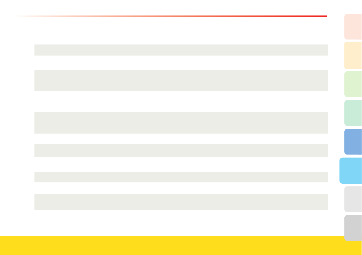
171
Table of Notes
5
6
2
1
3
8
7
4
Extreme caution required Subject Page ref.
Max. speed 149 mph - 240 km/h. Wheels and Tires
Page 27
The traction grade assigned to this tire is based on straight-ahead braking traction tests, and
does not include acceleration, cornering, hydroplaning, or peak traction characteristics.
Wheels and Tires
Page 28
The temperature grade for this tire is established for a tire that is properly inflated and not
overloaded. Excessive speed, under-inflation, or excessive loading, either separately or in
combination, can cause heat buildup and possible tire failure.
Wheels and Tires
Page 28
Observing the recommended wheel alignment values is essential in order to obtain the best
performance and the longest life of these tires. More information on these tires and on the relative
pressure monitoring system can be found in the “Carrozzeria Scaglietti” Owner’s Manual.
Wheels and Tires
Page 29
If you are going to use standard tires on a vehicle that was originally equipped with “Run
Flat” tires, you must contact your
Authorized Ferrari Dealer to have the dashboard
reprogrammed and to prevent viewing warning messages on the TFT display.
Wheels and Tires
Page 29
Safety
Ferrari urges you to use the seat belts correctly fastened and adjusted at all times! Seat belts
Page 34
Correct use of the seat belts can help reduce the risk of serious injury in the event of an
accident.
Seat belts
Page 34
All passengers must wear their seat belts!. Seat belts
Page 34
Do not pass the seat belts over sharp edges. They could tear. Seat belts
Page 34
Do not attach or pin anything onto the seat belts. This could reduce their initial strength
and cause them to tear in the event of a crash.
Seat belts
Page 34
172
Extreme caution required Subject Page ref.
Do not bring cutting edges in contact with a seat belt. They may get damaged and
consequently break in the event of a collision. If a seat belt has been brought in contact with
a cutting edge, or has been used to pin something on it, have it immediately replaced at your
Authorized Ferrari Dealer.
Seat belts
Page 34
Do not allow children to be held on a passenger’s lap using only one seat belt for both of
them. In the event of a crash, the weight of the adult would crush the child against the seat
belt. This can result in serious injuries or death for the child.
Seat belts
Fastening the seat belts
Page 36
After activation, the pretensioner no longer functions and cannot be repaired, under any
circumstances. Contact your Authorized Ferrari Dealer for replacement.
Seat belts
Pretensioners
Page 37
All work on any part of the safety system components must be performed only by an
Authorized Ferrari Dealer
.
Seat belts
Pretensioners
Page 37
Never drive with a child in a rearward-facing child seat in the front seat if the "PASSENGER
AIRBAG OFF" warning light is not illuminated. Airbag deployment can cause serious
injuries or death to a child in a rearward-facing child seat.
Child safety
Page 37
Established legislation in some countries already provides that children under 12 years of
age may not travel in the front passenger seat.
Child safety
Page 37
Child seats may only be installed with the seat fully lowered and pushed backward. Child safety
Page 37
Incorrect fastening of a child restraint system increases the risk of injury to the child in the
event of a collision.
Child safety
Page 37
Always deactivate this feature prior to using the seat belt for normal use. Having the retractor
locked can be dangerous when the seat belt is used for directly restraining a passenger.
Child safety
Page 38
Installing a child seat with the key in position II can result in induced injuries. Child safety
Page 38

173
Table of Notes
5
6
2
1
3
8
7
4
Extreme caution required Subject Page ref.
Never drive with a child in a rearward-facing child seat in the front seat if the
"PASSENGER AIRBAG OFF" warning light is not illuminated. Airbag deployment can
cause serious injuries or death to a child in a rearward-facing child seat.
Child safety
Page 39
Never carry a child in a adult’s lap. In the event of a crash, the weight of the adult could crush
the child against the seat belt (or the dashboard). This could result in serious injuries or death
for the child.
Child safety
Page 39
This is a high-performance vehicle. You are strongly urged not to carry children in this
vehicle, since they can also be injured by hard accelerations.
Child safety
Page 39
Always drive slowly and carefully when carrying a child. Hard accelerations due to sport-
style driving can be dangerous for children, even if no crash occurs.
Child safety
Page 39
Children must always be seated in a child restraint system specifically designed for their size,
and must be properly restrained.
Child safety
Page 40
Unrestrained occupants, including children, can be propelled against the dashboard or the
windshield by hard braking and by crash forces. This can result in serious injuries or death.
Child safety
Page 40
Do not tamper with seat belts or child restraint systems. Child safety
Page 40
The ignition key must always be turned to position 0 when installing a child seat on the front
passenger seat.
Child safety
Page 40
The advanced airbag system of your vehicle is not designed to protect adults with disability
that require deactivation of the passenger’s or driver’s airbag.
Child safety
Transport of person with
disability
Page 40
If you or another occupant is an adult with a medical condition that requires airbag
deactivation, please contact your Authorized Ferrari Dealer.
Child safety
Transport of person with
disability
Page 40
174
Extreme caution required Subject Page ref.
As long as the airbag is activated, persons with disability are advised not to travel in the
vehicle in order to avoid the risk of serious injuries or death, even in minor crashes.
Child safety
Transport of person with
disability
Page 40
The airbag is not a substitute for the seat belts. Correct use of the seat belts, in combination
with the airbag, will offer protection for the driver and passenger in the front seats in the
event of a head-on collision.
Airbag
Page 41
Front airbags cannot offer protection in side crashes, certain front-angular crashes, roll
over events or in secondary impacts (if a second crash happens after the airbags have been
deployed in a previous crash). The seat belts are designed to help reduce the risk of injuries
in roll over events and secondary front impacts. A properly fastened seat belt is needed to
help protect occupants in roll over events and secondary front impacts.
Airbag
Page 41
Front airbags are designed to not be deployed in low severity frontal crashes. The seat belts
can help reduce injuries in low severity crashes. A properly fastened seat belt is needed to
help protect the occupants in low severity frontal crashes.
Airbag
Page 41
When the ignition key is turned to position II, the warning light C illuminates. If no
malfunctioning is detected, it will go off after 4 seconds. If the warning light does not
illuminate, if it remains on or if it illuminates while driving, contact your Authorized Ferrari
Dealer immediately.
Airbag
Airbag system components
Page 41
The driver and passenger are both advised not to travel handling objects (e.g., beverage cans
or bottles, pipes, etc.) that could cause injury in the case of airbag deployment.
Airbag
Operation
Page 42
Always drive with your hands on the rim of the steering wheel so that, in case of activation,
the airbag can deploy without obstruction. Driving with your hands inside the steering
wheel rim or on the airbag cover increases the risk of injury for your wrists and arms.
Airbag
Operation
Page 42
The driver and passenger must always fasten their seat belts and sit in an upright position, as
far as possible away from the airbag, in order to help ensure protection in all types of collision.
Airbag
Operation
Page 42
175
Table of Notes
5
6
2
1
3
8
7
4
Extreme caution required Subject Page ref.
Always keep the backrest of your seat in the upright position and sit with your back properly
resting against it.
Airbag
Operation
Page 42
With the ignition key inserted and in position II, although the engine is off, the airbags can
still be activated when the vehicle is stationary if it is hit by a moving vehicle. Thus, even with
the vehicle stationary, do not put children in the front seat. In addition, remember that if
the ignition key is in position 0, none of the safety devices (airbags or pretensioners) will be
activated in the event of a collision. Failure of the airbags to inflate in these circumstances is
not indicative of a system malfunction.
Airbag
Operation
Page 42
Therefore, even with the vehicle stationary, do not allow children to sit on the front seat. Airbag
Operation
Page 42
Never place an object over or near the airbag covers. In the event that the airbags are
deployed, these objects would be projected into the passenger compartment at very
high speed. The object will be transformed into a projectile propelled in the passenger
compartment. This could cause serious injuries.
Airbag
Operation
Page 43
Never modify the airbag modules. Do not damage the airbag modules (for example pinning
something onto them or pressing objects against their covers). If, for any reason, an airbag
cover gets damaged, have the airbag module immediately checked by your Authorized
Ferrari Dealer. Activation of a damaged module could cause serious or fatal injuries.
Airbag
Operation
Page 43
Damaged or defective components of the airbag system cannot be repaired and must be
replaced. Improper operations performed on the system components may cause failures or
accidental deployment of the airbags with consequent damage and injury, even fatal.
Airbag
Operation
Page 43
The airbag modules must be replaced at the intervals indicated in the “Warranty and Service
Book” EVEN if the vehicle was NOT involved in a collision.
Airbag
Operation
Page 43
The airbags are not a substitute for the seat belts. Correct use of the seat belts, with the
supplementary action of the side bags, will provide protection in the event of a lateral collision.
Side Airbag
Page 44
176
Extreme caution required Subject Page ref.
The side bag fitted on the vehicle was not designed to reduce the risk of being hurled out
in the event of vehicle roll-overs.
Side Airbag
Side bag system components
Page 44
When the ignition key is turned to position II, the warning light B will illuminate. If no
malfunctioning in the airbag system is detected, it will go off after 4 seconds. If the warning
light does not illuminate, if it remains on or if it illuminates while driving, contact your
Authorized Ferrari Dealer immediately.
Side Airbag
Side bag system components
Page 44
Never travel with your head leaning out of the window, as your head and neck would be in the
airbag activation area. In the event of a side collision, this position would increase the risk of
being hurled out of the vehicle and would compromise the protective action of the side bags.
Side Airbag
Operation
Page 45
Never place an object over or near the airbag covers. In the event that the airbags are
deployed, these objects would be projected into the passenger compartment at very
high speed. The object will be transformed into a projectile propelled in the passenger
compartment. This could cause serious injuries.
Side Airbag
Operation
Page 45
Never modify the airbag modules. Do not damage the airbag modules (for example pinning
something onto them or pressing objects against their covers). If, for any reason, an airbag
cover gets damaged, have the airbag module immediately checked by your Authorized
Ferrari Dealer. Activation of a damaged module could cause serious or fatal injuries.
Side Airbag
Operation
Page 45
Following activation, the airbag components can no longer perform their protective action;
therefore, they cannot be repaired and must be replaced. After activation of a side bag, have
it replaced by your Authorized Ferrari Dealer.
Side Airbag
Operation
Page 46
The airbag modules must be replaced at the intervals indicated in the “Warranty and Service
Book” EVEN if the vehicle was NOT involved in a collision.
Side Airbag
Operation
Page 46
Do not carry adults in the front passenger seat if the “PASSENGER AIRBAG OFF” warning
light is illuminated, as the passenger airbag will not deploy in a frontal crash, thus reducing
the system’s ability to protect the occupant.
Advanced Airbag System
Page 47
177
Table of Notes
5
6
2
1
3
8
7
4
Extreme caution required Subject Page ref.
Do not carry children in rearward-facing child seats in the front passenger seat if the
“PASSENGER AIRBAG OFF” warning light is not illuminated, as the passenger airbag
could deploy in a frontal crash, seriously injuring or killing the child.
Advanced Airbag System Page 47
Never place an object over or near the driver’s or passenger’s airbags. In the event that the
airbag is deployed, it will project any object over it, or near it, in the passenger compartment
at very high speed. The object will be transformed into a projectile propelled in the
passenger compartment. This could cause serious injuries.
Advanced Airbag System
Page 49
Seat belts are designed to help minimize injury severity in the event of an accident. To help
achieve optimal protection for adults, the airbags should supplement the seat belts. Always
wear your seat belts properly fastened.
Advanced Airbag System
Page 49
Front airbags cannot offer protection in side crashes, certain front-angular crashes, roll
over events or in secondary impacts (if a second crash happens after the airbags have been
deployed in a previous crash). The seat belts are designed to help reduce the risk of injuries
in roll over events and secondary front impacts. A properly fastened seat belt is needed to
help protect occupants in roll over events and secondary front impacts.
Advanced Airbag System
Page 49
Front airbags are designed to not be deployed in low severity frontal crashes. The seat belts
can help reduce injuries in low severity crashes. A properly fastened seat belt is needed to help
protect occupants in low severity frontal crashes.
Advanced Airbag System
Page 50
To help ensure protection in the event of a collision, you must be in a normal seated position
with your back against the seat backrest. The passenger’s feet must be on the footrest. The
driver’s left foot must be on the footrest.
Advanced Airbag System
Page 50
Adjust your seat as far back as possible, ensuring you can operate the vehicle controls properly
and comfortably. Keep your hands on the steering wheel rim, without crossing them. Placing
your hands or arms inside the rim increases the risk of hand/arm injuries in the event of a
crash with driver’s airbag deployment.
Advanced Airbag System
Page 50
178
Extreme caution required Subject Page ref.
Never place your feet on the dashboard or the instrument panel or out of the window, as this
will seriously affect the ability of the system to protect you in the event of a crash, and can
result in induced injuries in the event of airbag deployment.
Advanced Airbag System
Page 50
Adults should not travel in the front passenger seat if the “PASSENGER AIRBAG OFF”
warning light is illuminated.
Occupant Classification
System
Page 51
Children in a rearward-facing child seat must not travel in the front passenger seat if the
“PASSENGER AIRBAG OFF” warning light is not illuminated.
Occupant Classification
System
Page 51
Installing a child seat with the ignition key in position II can result in induced injuries. Occupant Classification
System
Page 51
Do not carry adults in the front passenger seat if the “PASSENGER AIRBAG OFF” warning
light is illuminated, as the passenger airbag will not deploy in a frontal crash, thus reducing
the system’s ability to protect the occupant.
Occupant Classification
System
Page 53
Do not carry children in rearward-facing child seats in the front passenger seat if the
“PASSENGER AIRBAG OFF” warning light is not illuminated, as the passenger airbag
could deploy in a frontal crash, causing serious injury or death.
Occupant Classification
System
Page 53
The front passenger’s seat and its control unit are part of the advanced airbag system. Never have
your seat tampered with, as this can result in a system malfunction, which could cause serious
injuries or death.
Occupant Classification
System
Page 53
Repairs on the front passenger seat must only be performed by trained technicians at an
Authorized Ferrari Dealer.
Occupant Classification
System
Page 53
Not following the above instructions can result in serious injuries or death in the event of a
crash.
Advanced Airbag System
Page 53
The ABS system features remain unaltered as long as the speed limit for the tire side grip is
not exceeded. When this limit is exceeded, vehicle skidding cannot be avoided.
ABS
Page 54
179
Table of Notes
5
6
2
1
3
8
7
4
Extreme caution required Subject Page ref.
The ABS system does NOT exempt the driver from driving carefully and responsibly at all times.
ABS
Page 54
RACE mode must be used only on race tracks. CST
Page 55
The system warns the driver that the tire pressure has decreased. However, this does NOT
exempt the driver from periodically checking that the tires are inflated to the indicated
pressure. In addition, the system is UNABLE to warn the driver of sudden damage to the tires
caused by external objects/agents (e.g., nails, stones, etc.).
Tire pressure and temperature
monitoring system
Page 56
Before calibrating the system, make sure that the tire pressures correspond to the indicated
pressure values (see page 24-25). If this is not the case, the system may issue wrong low
pressure indications.
Tire pressure and temperature
monitoring system
System not calibrated
Page 59
About your
vehicle
Always check that the doors are properly closed to prevent them from opening while driving. Door opening and closing
Door locking and opening
from the inside
Page 68
Always check that the lid is properly closed to prevent it from opening while driving. Engine compartment lid
Closing
Page 69
Always turn off the engine during refueling. Take extreme care when removing the cap. Do not
smoke or use open flames during refueling. The following can be harmful for your health:
- fuel coming into contact with your skin
- inhaling fuel vapors.
Fuel tank door and cap open-
ing and closing
Page 71
Improper use of the power windows can be dangerous. Before use, always check that people
and objects are at a safe distance.
Pay particular attention during the automatic operation
of the driver-side power window.
To protect the passengers remaining in the car against
accidental operation of the power windows, always remove the key from the ignition.
Power window opening and
closing
Page 73
180
Extreme caution required Subject Page ref.
If the high beam control is on, the high beams will turn on every time the external lights
are activated automatically. We recommend therefore that you turn them off every time the
twilight sensor deactivates the external lights.
Lighting
Automatic activation and
deactivation
Page 75
In case of fog during the day, the position lights and low beams will not activate
automatically. The driver must always be ready to turn on the lights manually, and also the
rear fog lights if necessary.
Lighting
Automatic activation and
deactivation
Page 75
The driver is always responsible for turning on the external lights, depending on the
ambient light and in compliance with the regulations in force in the country of use. The
automatic system for turning on and off the external lights must be considered an aid for
the driver. If necessary, turn the lights on and off manually.
Lighting
Automatic activation and
deactivation
Page 75
RACE mode must be used only on race tracks. “TFT” display
Page 81
Stop the vehicle avoiding hard braking. Do not drive further and contact an Authorized
Ferrari Dealer immediately.
Instruments and gauges
TFT display warning lights
Page 88
The vehicle can still be driven at low speed (max. 25 mph – 40 km/h), to leave the road. Instruments and gauges
TFT display warning lights
Page 88
In this condition, do not activate “SPORT” or "RACE" mode. Instruments and gauges
TFT display warning lights
Page 89
Stop the vehicle avoiding hard braking. Do not drive further, check the fluid level in the tank
and immediately contact your Authorized Ferrari Dealer.
Instruments and gauges
Warning lights
Page 91
Stop the vehicle avoiding hard braking. Do not drive further and immediately contact your
Authorized Ferrari Dealer
.
Instruments and gauges
Warning lights
Page 91
The vehicle can still be driven at low speed (max. 25 mph – 40 km/h), to leave the road.
Instruments and gauges
Warning lights
Page 91
Danger of rear wheels locking and risk of spinning. Stop the vehicle avoiding hard braking.
Do not drive further and immediately contact your Authorized Ferrari Dealer.
Instruments and gauges
Warning lights
Page 91
181
Table of Notes
5
6
2
1
3
8
7
4
Extreme caution required Subject Page ref.
The vehicle can still be driven at low speed (max. 25 mph – 40 km/h), to leave the road. Instruments and gauges
Warning lights
Page 91
RACE mode must be used only on race tracks. Instruments and gauges
Warning lights
Page 96
Do not operate the windshield washer during the cold months until the windshield has
warmed up. If it has not warmed up, the liquid could freeze on the glass and block the view.
Windshield washer/wipers
and headlight washer
Windshield washer
Page 98
Before cleaning the front windshield (for example in service stations) make sure the rain sensor
is deactivated or that the key is at position 0. The rain sensor must be deactivated also when
washing the vehicle by hand or in automatic car washes. In case of ice or snow on the front
windshield, do not activate the rain sensor to avoid damaging the wiper motor and/or blades.
Windshield washer/wipers
and headlight washer
Rain sensor
Page 99
BEFORE YOU DRIVE
Check that the seat belts are fastened.
Check that the doors are closed.
Check that the seat is properly adjusted.
Check the rear-view mirror adjustment (center and sides).
Driving the vehicle
Page 100
Use unleaded fuel only! Using leaded fuel would permanently damage the catalytic converters. Driving the vehicle
Recommended lubricants and
fluids
Page 100
If the failure warning light continues flashing without going off, deactivate the system and
restart it. If the failure persists, contact an Authorized Ferrari Dealer to have the necessary
checks performed.
Driving the vehicle
Starting and driving the
vehicle (F1)
System starting
Page 101
182
Extreme caution required Subject Page ref.
If a horizontal dash appears on the display, there is a system failure. Driving the vehicle
Starting and driving the
vehicle (F1)
Operation with the engine off
Page 101
Hold button R down, until the letter R appears on the display.
Driving the vehicle
Starting and driving the
vehicle (F1)
Operation with the engine off
Page 102
Hold the brake pedal down while starting the engine. Driving the vehicle
Starting and warming up the
engine (F1)
Page 102
Use 1st gear for parking or for starting uphill.
Driving the vehicle
Starting the vehicle (F1)
Page 103
The buzzer may also sound to warn the driver that the clutch is starting to overheat. This
may occur if you use the accelerator pedal when the vehicle is stationary on a hill or during
the “pick-up” maneuver.
Driving the vehicle
Starting the vehicle (F1)
Page 104
RACE mode must be used only on race tracks. F1 - SUPERFAST gearshifting
Page 105
Do not start the vehicle before the display has turned off. Never leave the vehicle with the
gearshift in N. Engage a gear (1st or R), check that the display is not flashing and always
apply the handbrake. Never leave the vehicle with the engine running.
Driving the vehicle
Turning off the engine and
the system (F1)
Page 106
Never remove the key when the vehicle is moving! The system and the display will remain
active, but malfunctioning, until the vehicle is stopped. In addition, the steering wheel will
lock automatically with the first turn of the steering wheel.
Driving the vehicle
Turning off the engine and
the system (F1)
Page 106
Use 1st gear for parking or for starting uphill.
Driving the vehicle
Starting the vehicle (CM)
When the engine has started
Page 108

183
Table of Notes
5
6
2
1
3
8
7
4
Extreme caution required Subject Page ref.
Continuing to drive when a red warning light is on could cause serious damage to the
vehicle and affect its operation and performance. After sports-style driving, let the engine
idle for several minutes before turning it off, in order to stabilize the temperatures.
Driving the vehicle
While driving (CM)
Page 109
Do not coast downhill with the engine off, as the servo brake will no longer function due to
the vacuum decrease and thus, after a less braking attempts, the system will become inefficient.
Driving the vehicle
While driving (CM)
Page 109
Never leave children unattended in the vehicle. Do not park the vehicle on flammable materials
(e.g., paper, grass, dry leaves, etc.). They could catch fire if they come into contact with hot parts
of the exhaust system. Do not leave the engine running with the vehicle unattended.
Driving the vehicle
Parking
Page 109
To help ensure the system proper functioning, the sensors positioned on the bumper must
be kept clean (remove any mud, dirt, snow or ice).
Driving the vehicle
Parking maneuver
Page 110
However, the driver remains fully responsible for parking maneuvers and in other
potentially dangerous situations. The system has been designed only as a supplementary aid
during parking maneuvers, since it allows the driver to detect obstacles outside his field of
vision. Use of the sensors therefore does not mean that the driver can be less careful and
attentive and not watch out for persons and obstacles during parking maneuvers.
Driving the vehicle
Parking maneuver
Page 110
The driver is fully responsible for parking and other potentially dangerous maneuvers.
During these maneuvers, always make sure there are no people (especially children) or
animals in the maneuvering area. The parking sensors must be considered an aid for the
driver who, in any case, must never take less care during potentially dangerous maneuvers,
even if they are performed at low speeds.
Driving the vehicle
Parking maneuver
Failure warnings
Page 111
184
Extreme caution required Subject Page ref.
Drunk driving, or driving under the influence of drugs, alcohol or certain medicines is extremely
dangerous for yourself and others. Traveling without your seat belt fastened increases the risk of
serious injury and death in the event of a collision. Always fasten the seat belt and the child seat,
if any. Deactivate the passenger’s airbag (where possible) if a child seat is fitted on the front seat.
Do not travel with objects lying around on the floor, especially in front of the driver’s seat: in the
event of braking, these could slide under the pedals, making it impossible to brake or accelerate.
Additionally, ensure that any floor mats fit correctly. Water, ice and salt spread on icy roads may
deposit on the brake discs and reduce the efficiency of the initial braking.
Driving the vehicle
Safe driving
When travelling
Page 112
If the road is wet, reduce your speed to avoid “aquaplaning” phenomena, during which the tire
no longer touches the road surface. This is due to the fact that, when the road is very wet and
the vehicle speed is high, the side channels of the tire tread, because of their particular shape
or insufficient depth, are not capable of removing all of the water channelled, so that a layer of
water exists between the road surface and the tire. The fluid pressure generated is so high as
to support the vehicle’s weight, making it impossible for the driver to control the vehicle.
Driving the vehicle
Safe driving
When travelling
Page 113
On stretches where visibility is good, turn off the rear fog lights, as they are very bright and
may be annoying for the occupants of the vehicles behind you.
Driving the vehicle
Safe driving
Driving in fog
Page 114
RACE mode must be used only on race tracks. Ignition switch
Position II - Start
Page 116
Never remove the key when the vehicle is moving! The steering wheel will lock automatically
with the first turn of the steering wheel. Always remove the key from the ignition when you
get out of the vehicle! Never leave children unattended in the vehicle.
Ignition switch
Position II - Start
Page 116
Always apply the handbrake when the vehicle is parked. After hearing a series of clicks by
pulling the handbrake lever, the vehicle should be blocked. If this is not the case, please
contact your Authorized Ferrari Dealer
Handbrake lever
Page 117
185
Table of Notes
5
6
2
1
3
8
7
4
Extreme caution required Subject Page ref.
Never adjust the seat while driving: you may lose control of the vehicle. Adjustments
Seat adjustments
Page 118
Sitting in a reclined position while the vehicle is in motion could be dangerous. The
backrest should not be tilted too far back. The 3-point shoulder/lap belt must be firmly
secured against the occupant’s body in order to function properly. Therefore, both the
driver and passenger’s backrests must always be in an upright position while the vehicle is
in motion; otherwise the 3-point shoulder/lap belt would not remain firmly secured against
the occupant’s body. Serious injury could result.
Adjustments
Seat adjustments
Page 119
Do not adjust the steering wheel when the vehicle is moving. Adjustments
Steering wheel adjustment
Page 120
Keep the glove compartment closed while driving. Passenger compartment
accessories
Glove compartment
Page 126
Do not use the cigarette lighter seat as a power socket for electrical items of any kind! The
cigarette lighter reaches very high temperatures. Handle it with care to avoid risk of burns
and fire. It is possible to connect the emergency tire repair and inflation kit ONLY for the
time necessary for the operation.
Passenger compartment
accessories
Ashtray
Page 127
Advice for Emergency
situations
In the event of repairs performed using the toolkit provided, you must:
- use suitable personal protection (e.g., gloves)
- take suitable precautions (e.g., when changing a tire, never lie under the vehicle raised on the
jack)
- have the basic and specific skills required for working with electrical parts/components.
Advice for Emergency
situations
Page 130
186
Extreme caution required Subject Page ref.
After using the repair kit, the vehicle must however be considered to be in an emergency
situation: drive with the utmost care (maximum permissible speed 50 mph – 80 km/h). The
kit is to be used to temporarily repair only one tire punctured by small objects: the kit may
not be useful in the case of large punctures or tearing.
Toolkit
Emergency tire repair and
inflation kit
Page 130
Keep the kit in its box and out of children’s reach. Do not inhale or swallow the fluid
contained in the cartridge and avoid contact with the skin and eyes.
Toolkit
Tire inflation and repair kit
for emergency situations
Page 131
The sealant contained in the cartridge in the tire repair kit may damage the sensor fitted inside
the wheel rim on vehicles equipped with the tire pressure monitoring system. In these cases,
always have the sensor replaced by an Authorized Ferrari Dealer.
Toolkit
Tire inflation and repair kit
for emergency situations
Page 131
If the jack is not positioned correctly, the vehicle could slip off. The jack supplied must only be
used for replacing the wheels.
Replacing a wheel
Replacing a wheel
Page 152
Inflate the collapsible spare wheel before lowering the car, as otherwise the rims may
be damaged
Replacing a wheel
Replacing a wheel
Page 152
The kit must be used in “tire inflation” mode.
Use lever terminal H.
Replacing a wheel
Replacing a wheel
Page 152
The spare wheel is not equipped with the tire pressure monitoring sensor (see label on
spare wheel bag). After installation, it is not monitored by the system, but it does comply
with International Regulation ECE R64/01. Once fitted, we recommend you go to the
nearest Authorized Ferrari Dealer.
Replacing a wheel
Replacing a wheel
Page 152
Always follow the applicable driving and traffic regulations when the vehicle is being towed. Towing hook
Page 153
Do not tow the vehicle using a hook attached to the suspension levers and wheel rims, but
only onto the towing hook properly fitted in its seat.
Keep the ignition key in position II to
allow the lights to work and to prevent locking of the steering wheel in the event of steering.
Do not start the engine when towing the vehicle.
Towing hook
Page 153

187
Table of Notes
5
6
2
1
3
8
7
4
Extreme caution required Subject Page ref.
The system can be reactivated by pressing the button on top of the switch. Fuel inertia switch
Page 153
Never disconnect the battery from the electrical system when the
engine is running. Before disconnecting the battery, lower the side windows by at least
0.78–1.18 in. (2–3 cm) to avoid damaging the weather strips when opening and closing the doors.
Battery master switch
Page 154
This operation, when the battery is connected and fully charged, is done automatically whenever
the doors are opened or closed. The windows must remain lowered until the recharged battery is
reconnected. If the battery is discharged and the windows are fully up, only open the doors when
strictly necessary and being extremely careful. Do not close them again until the windows can be
lowered.
Battery master switch
Page 154
The battery does not need refilling with distilled water or sulphuric acid. Checking the battery
Page 155
Keep the battery away from sources of heat and do not use open flames or create sparks near it. Checking the battery
Page 155
Arrange the battery conditioner in a well visible position, away from heat sources and children's reach.
Checking the battery
Battery conditioner
Page 155
The vehicle cannot be started (ignition disabled) as long as the battery conditioner is
connected to the socket in the vehicle.
Checking the battery
Battery conditioner
Page 156
If the temperature is extreme (light on steady):
The temperature in the catalytic converters has reached a dangerous level and could
damage them. If you continue to drive, the engine ECU will cut off the fuel supply to the
injectors.
The driver must stop the vehicle and turn off the engine so the exhaust system can cool
down. After about five minutes, restart the engine and drive normally.
If the OBD warning light illuminates (see page 157) at the same time, it is necessary to
contact and Authorized Ferrari Dealer to check the control unit’s memory for errors.
Ferrari is not liable for any damage to property or personal injury arising from failure to
comply with the warnings stated above.
Exhaust system overheating
alarm devices
Page 156
188
Extreme caution required Subject Page ref.
When the warning light “Engine control system failure” illuminates, engine performance
may be considerably reduced. Drive carefully, avoiding sudden accelerations and high
speeds. Contact an Authorized Ferrari Dealer immediately.
Engine malfunction alarm
devices
Page 157
In order to help ensure the quality of the components and accurate installation, we recommend
that you have the procedure performed by your Authorized Ferrari Dealer. To help ensure
proper breaking-in of the pads following replacement, avoid sudden and sharp braking until the
new pads have been run-in, after about 186 mi (300 km).
Replacing the brake pads and
brake discs
Replacing the brake pads
Page 157
Care of the Vehicle
The Warranty and Service Book also contains special blank spaces where the Authorized
Ferrari Dealer can register the regular maintenance services performed, as indicated in the
maintenance schedule.
Warranty and Service Book
Page 160
If the oil level is not checked within 3 minutes (instead of 2 minutes, as indicated above), repeat
steps B and C before checking the level.
Level checks
Engine oil
Page 161
If the oil level is below the “MIN” notch, top it up and then have the system checked by your
Authorized Ferrari Dealer.
Level checks
Engine oil
Page 161
As the first check was performed within a time range of 2-3 minutes, the second oil check must
also be performed within the same time range.
For instance, if the first check was performed after 2 min. and 30 sec., the second check must also
be performed after approximately 2 min. and 30 sec..
Level checks
Engine oil
Page 161
This procedure must always be performed when the engine is cold. Never remove the cap C
from the expansion tank when the engine is running or hot.
Level checks
Coolant
Page 162
The oil contained in the brake and clutch systems, in addition to damaging plastic, rubber
and painted parts, is highly dangerous if it comes into contact with the eyes or the skin. In
case of contact, wash the affected part thoroughly with running water. To avoid any risk,
always use protective goggles and gloves. Keep out of children’s reach!
Level checks
Brake/clutch fluid
Page 164

189
Table of Notes
5
6
2
1
3
8
7
4
Extreme caution required Subject Page ref.
The use of mineral-based fluids will irreparably damage the system rubber gaskets. Do not
use fluids other than those already contained in the system for refills.
Level checks
Brake/clutch fluid
Page 164
Inflating the tires to a pressure differing from that prescribed (see table on page 28) will
render the monitoring system inefficient.
Wheels and tires
How to use the tires
Page 165
We recommend that you replace the tires when worn to a depth of less than 0.067 in (1.7
mm), but in no case should they be kept on the vehicle for more than four years, even
if sufficient tire tread remains. Frequent use in maximum load conditions and at high
temperatures may accelerate aging.
Wheels and tires
How to use the tires
Page 165
The tires are of the “directional” type and there is an arrow marked on their side to indicate
the direction in which they must rotate or which side is the outer side. In the case of
replacement, the best performance levels can only be provided if the rotation direction
corresponds with the direction indicated by the arrow. Tires on the same axle must always be
replaced in pairs.
Wheels and tires
How to use the tires
Page 165
Drive carefully on wet roads to reduce the risk of “aquaplaning”. Wheels and tires
How to use the tires
Page 165
All work on any part of the safety system components may only and exclusively be
performed by an Authorized Ferrari Dealer
.
Maintenance of the seat belts
and pretensioners
Page 166
Do not use aggressive substances to clean the windows. Using aggressive substances may
damage some parts of the body.
Cleaning the vehicle
Cleaning of the exterior
Page 166
When the vehicle has been washed, apply slight pressure to the brake pedal at moderate speed
before driving at a normal speed, until the brake discs and pads have cleaned off.
Cleaning the vehicle
Cleaning of the exterior
Page 166

1. General
2. Safety
3. About your Vehicle
4. Advice for Emergency Situations
5. Care of the Vehicle
6. Table of Notes
7. Glossary
8. Index

Glossary

192

193
8
7
6
4
5
2
1
3
Glossary
Abbreviation Meaning
ABS
The ABS system is designed to prevent wheel locking during braking and helps the driver to maintain full
steering control over the vehicle.
A.C.
Air Conditioning.
ASR
Anti-skid regulation during acceleration.
AUTO easy
exit
AUTO easy exit mode. To exit the “AUTO easy exit” mode, shift one of the two gearshift levers.
Traction
power
Force transmitted by the vehicle to the road surface through the wheels; it indicates the grip.
CST
Traction Stability Control.
“TFT” display
Thin Film Transistor display on the instrument panel, that shows information about the control system.
ECU
Electronic Control Unit.
Xenon
headlights
The Xenon headlights produce a brighter light beam and use a voltaic arc instead of an incandescent filament.
F1
Electronically-controlled gearbox, designed with the same technology as used in the racing sector.
F1-Trac
Traction control derived from the technologies used in the racing sector.
OBD
On-Board Diagnostic system.
VDC
Vehicle dynamics control using the braking system and engine torque.

1. General
2. Safety
3. About your Vehicle
4. Advice for Emergency Situations
5. Care of the Vehicle
6. Table of Notes
7. Glossary
8. Index

Index

196
Index
A
Abbreviations/Meanings ............................ 5
ABS ................................................................... 54
Adjusting the seat belt height ...............
34
Adjusting the steering wheel ............... 120
Air conditioning and
heating system ............................................. 122
Airbag .............................................................. 41
Alarm system .................................................. 12
Ashtray ............................................................ 127
“AUTO easy exit” mode ........................... 107
“Automatic gearshift” mode ................. 106
B
Battery master switch .............................. 153
Battery conditioner .................................. 155
Before you drive ........................................
112
Body Computer fuses and relays ....... 142
C
Chassis – Bodywork ................................ 160
Checking the brake/clutch
fluid level ...................................................... 163
Checking the engine oil level ..............
161
Checking the coolant fluid level ........ 161
Checking the F1 gearbox oil level .... 161
Checking the hydraulic steering
oil level .......................................................... 163
Child safety .................................................... 37
Cleaning the vehicle ................................ 166
Clothing hooks .......................................... 127
Consulting the Manual ................................ 4
Coolant .......................................................... 161
CST ...................................................................
54
CST OFF mode ........................................... 96
D
Dimensions and weights .......................... 23
Direction indicators ................................... 76
Doors ................................................................ 68
“DOWN” gearshift lever .......................... 97
Driver’s seat position memory ............. 119
Driver-side power window ..................... 72
Driving at night .......................................... 113
Driving in fog ............................................. 114
Driving in the rain .................................... 113
Driving on mountain roads .................. 114
Driving on snowy or icy roads ............ 114
Driving style ..................................................... 7
Driving the vehicle ..................................... 99
Driving the vehicle
(Mechanical Gearbox) ............................ 108
Driving the vehicle (F1) ........................ 103
Driving with the “ABS”
braking system ........................................... 114
Duplicating the keys .................................. 14
E
Electrical system .......................................... 26
Electronic alarm ..........................................
16
Electronic speedometer ............................ 90
Emergency starting .................................... 15
Engine compartment lid .......................... 69
Engine malfunction alarm devices .... 157
Engine oil temperature gauge ............... 92
Engine pressure gauge ............................. 92
Environmental protection .......................... 7
Exhaust system overheating
alarm devices .............................................. 155
External rear-view mirrors .................... 121
F
F1 – SUPERFAST gearshifting ........... 105
Fastening the seat belts ............................ 35
Filling the cooling circuit ...................... 162
Fuel Consumption ...................................... 25
Fuel inertia switch .................................... 153
Fuel level gauge ........................................... 84
Fuel tank cap and door ..............................
71
Fuses and relays in the engine
compartment ............................................... 141
Fuses and relays in the luggage
compartment ............................................... 149
Fuses and relays in the passenger
compartment (driver-side) ................... 145
Fuses and relays in the passenger
compartment (passenger’s side) ......... 147

197
8
7
6
4
5
2
1
3
Index
G
Gear display (F1) ........................................ 91
Gearshifting (F1 gearbox) .................... 104
Glove compartment .................................. 125
H
Handbrake lever ........................................ 117
Hazard warning lights ............................... 77
Headlight washer ........................................ 98
Horn control ................................................. 97
How to use the tires ................................ 164
I
ICE mode ....................................................... 95
Identification plates and labels .............
18
If the vehicle is stored
for long periods ......................................... 167
Ignition switch ........................................... 116
Instrument panel ......................................... 78
Internal rear-view mirror ....................... 120
L
Light switch ................................................... 73
Light bulbs ...................................................138
Location of the fuse
and relay boxes ........................................... 140
LOW GRIP mode .......................................
95
Luggage compartment lid ....................... 70
M
Main engine specifications ...................... 24
Maintenance of the seat belts and
pretensioners .............................................. 166
Maintenance schedule ............................ 160
Maintenance ................................................ 160
O
Occupant Classification System ............ 50
Operation with the engine off (F1) .. 101
Overview of controls ................................. 64
P
Parking ........................................................... 109
Passenger-side power window .............. 72
Performance ..................................................
24
Pocket-change compartments ..............
126
Power windows ............................................ 72
Pretensioners ................................................ 36
Push start (F1) ........................................... 107
Push start (Mechanical Gearbox
) ...... 108
R
RACE mode .................................................. 96
Rain sensor .................................................... 98
Recharging the battery ........................... 154
Recommended lubricants
and fluids ....................................................... 30
Replacing a fuse ........................................ 139
Replacing a wheel ..................................... 151
Replacing other light bulbs .................. 136
Replacing the auxiliary stop
light and side marker bulbs ................. 136
Replacing the brake pads
and brake discs .......................................... 157
Replacing the front direction
indicator and position light bulbs .... 133
Replacing the low beam/high beam
light bulbs .................................................... 133
Replacing the license plate
light bulb ...................................................... 136
Replacing the position light bulbs .... 133
Replacing the taillight bulbs ................ 135
Roof panel controls .................................... 94
S
Safe driving ................................................. 112
Seat belts ........................................................ 34
Seats ............................................................... 118
Service ................................................................ 4
Spare parts ........................................................ 6
SPORT mode ...............................................
95
Start button ................................................... 95
Starting and warming up the engine
(F1 gearbox) ............................................... 102
Stopping the vehicle (F1 gearbox) ...
105
Sun radiation sensor ................................ 125
Sun visors ..................................................... 127
System starting ........................................... 100

198
T
Tachometer .................................................... 90
TFT display ................................................... 79
TFT display buttons .................................. 80
TFT display warning lights ..................... 86
Tire pressure and temperature
monitoring system ...................................... 55
Tire pressure calibration button ........... 94
Toolkit ............................................................ 130
Towing hook ...............................................
152
Transmission ratios ..................................... 24
Turning off the engine and
the system (F1 gearbox) ........................ 106
Twilight sensor ............................................. 75
U
Updating ............................................................ 6
“UP” gearshift lever ................................... 97
V
Vehicle keys ................................................... 12
W
Warning lights .............................................. 91
Warranty and Service Book .................. 160
Water temperature gauge ........................ 92
Wheel and tires ............................................
26
Wheels and tires ........................................ 164
When traveling ...........................................
112
While driving
(Mechanical Gearbox) ............................ 108
Windshield washer ..................................... 97
Windshield wipers ...................................... 97
Windshield washer fluid ......................... 164