Home
Bookmarks
Home
Bosch
Bosch PKM845F11E User Manual
Page 10
User Manual - Page 10
For PKM845F11E. Series: Serie | 6
Page 10/27
Page 1
Page 2
Page 3
Page 4
Page 5
Page 6
Page 7
Page 8
Page 9
Page 10
Page 11
Page 12
Page 13
Page 14
Page 15
Page 16
Page 17
Page 18
Page 19
Page 20
Page 21
Page 22
Page 23
Page 24
Page 25
Page 26
Page 27
Contents
Table of Contents
Search
Previous
Next
Bookmarks
Loading ...
Loading ...
Loading ...
7
Loading ...
Loading ...
Loading ...
<
7
8
9
10
11
12
>
File type: PDF
File name: 64533325_pkm845f11e.pdf
File size: 2.76 MB
File Language: English, French, German, Dutch - Holland, Italian
Pages: 27
Author: Bosch
File created: 2019-03-27
Published: 2021-04-14
Updated: 2023-06-02
Verified by
Clementina Bode
on 2023-06-02
Download File
Table of Contents
×
Ø Montageanleitung
14
: Wichtige Sicherheitshinweise
14
Diese Anleitung sorgfältig lesen. Nur dann können Sie Ihr Gerät sicher und richtig bedienen. Die Gebrauchs- und Montageanleitung für einen späteren Gebrauch oder für Nachbesitzer aufbewahren.
14
Nur bei fachgerechtem Einbau entsprechend der Montageanleitung ist die Sicherheit beim Gebrauch gewährleistet. Der Installateur ist für das einwandfreie Funktionieren am Aufstellungsort verantwortlich.
14
Träger von elektronischen Implantaten!
14
Der Hersteller übernimmt keine Verantwortung für Betriebsstörungen oder mögliche Schäden die auf eine fehlerhafte elektrische Installation zurückzuführen sind.
14
Netzkabel:Das Netzkabel darf nur von einer zugelassenen Fachkraft oder von einem ausgebildeten Kundendiensttechniker installiert werden. Die erforderlichen Anschlussdaten befinden sich auf dem Typenschild und in den Anschlussplänen.
14
Vor der Durchführung jeglicher Arbeiten die Stromzufuhr abstellen.
14
Für die Installation müssen die aktuell gültigen Bauvorschriften und die Vorschriften der örtlichen Strom- und Gasversorger beachtet werden.
14
Bei der Ableitung von Abluft sind die behördlichen und gesetzlichen Vorschriften (z.B. Landesbauordnungen) zu beachten.
14
Lebensgefahr!
14
Lebensgefahr!
14
Brandgefahr!
14
Verletzungsgefahr!
14
Verletzungsgefahr!
14
Verletzungsgefahr!
14
Erstickungsgefahr!
14
Dieses Gerät nicht auf Booten oder in Fahrzeugen einbauen.
14
Arbeitsplatte: Sie muss eben, horizontal und stabil sein. Die Anweisungen des Arbeitsplatten-Herstellers beachten.
14
Wenn die Dicke der Arbeitsplatte, in die das Kochfeld eingebaut wird, nicht den Vorgaben entspricht, die Arbeitsplatte mit feuer- und wasserfestem Material verstärken, bis die empfohlene Mindestdicke erreicht ist. Andernfalls ist keine ausreichende ...
14
Hinweise
14
Allgemeine Hinweise
14
Abluftbetrieb
14
Hinweis
14
Abluftleitung
14
Hinweis
14
Umluftbetrieb
15
Hinweis
15
Elektrischer Anschluss
15
Installation vorbereiten
15
Gerätemaße und Sicherheitsabstände
15
Möbel überprüfen
15
Hinweis
15
Möbel vorbereiten
15
1. Den Ausschnitt in der Arbeitsplatte gemäß der Einbauskizze herstellen. (Bild 1)
15
Hinweis
15
2. Beim Einbau über einem Schubfach Mindestabstände einhalten. (Bild C)
15
3. Das oberste Schubfach entfernen und am Möbel eine entsprechend passende Verblendung anbringen.
15
Möbel und Gerät für Umluftbetrieb vorbereiten
15
Möbelausschnitt herstellen
15
1. In der Sockelleiste des Möbels einen Luftauslass herstellen.
15
Hinweis
15
2. Möbelrückwand entfernen.
15
3. Bei Bedarf obere Leiste an der Möbelrückwand entfernen.
15
4. Am hinteren Rand des Arbeitsplattenausschnitts den Mittelpunkt bestimmen und diesen und die beiden Linien senkrecht nach unten auf dem Möbelboden abbilden. (Bild 2a)
15
5. Fixierungsblech auf dem Möbelboden an den Mittellinien ausrichten. (Bild 2b)
15
6. Bei Schubladen: Unterste Schublade vollständig schließen. Falls das Fixierungsblech zu weit unter der Schublade verschwindet, dieses in Richtung Möbelrückseite verschieben. Mit Hilfe der Markierungen im Fixierungsblech dieses parallel zur Mitt...
15
Hinweise
15
7. Falls notwendig Ausschnitt im Möbelboden mit Hilfe des Fixierungsbleches anzeichnen und herstellen. (Bild 2d)
15
8. Nach Ausschnittarbeiten Späne entfernen.
15
Hinweis
15
Fixierungsblech festschrauben und Diffusor festklipsen
15
1. Falls der Abstand zwischen Schublade und Möbelboden ausreicht, das Fixierungsblech mit Kunststoffschrauben von oben am unteren Flachkanalbogen festschrauben. (Bild 3a)
15
Hinweis
15
2. Fixierungsblech mit Holzschrauben von oben am Möbelboden festschrauben. (Bild 3a)
15
Hinweis
15
3. Diffusor am unteren Flachkanalbogen festklipsen. (Bild 3c)
15
Oberen Flachkanalbogen montieren
15
1. Bei Bedarf die Verlängerung abhängig von der Position des Fixierungsblechs und der Möbeltiefe wählen. Je länger die Verlängerung, umso tiefer kann die Schublade sein. Verlängerung mit vier Kunststoffschrauben an der Auslassöffnung des Koch...
15
Hinweis
16
2. Oberen Flachkanalbogen an der Auslassöffnung des Kochfelds oder an der Verlängerung festschrauben.
16
Möbel und Gerät für Abluftbetrieb vorbereiten
16
1. Reduzierstutzen oder Flachkanalbogen mit vier Kunststoffschrauben an der Auslassöffnung des Kochfelds oder an der Verlängerung festschrauben. (Bild 5)
16
Hinweise
16
2. Je nach Abluftkonfiguration für das Abluftrohr einen Ausschnitt in der hinteren Möbelwand herstellen, Möbelrückwand entfernen oder einen Ausschnitt im Möbelboden herstellen.
16
3. Nach Ausschnittarbeiten Späne entfernen.
16
Hinweis
16
Gerät montieren
16
: Stromschlaggefahr!
16
: Verletzungsgefahr!
16
Kochfeld einsetzen
16
1. Halteschienen anbringen. (Bild 6a)
16
2. Das Gerät in den Arbeitsplattenausschnitt einsetzen. (Bild 6b)
16
Gerät anschließen
16
Hinweise
16
Abluftverbindung herstellen
16
1. Abluftrohr am Flachkanalbogen oder Reduzierstutzen befestigen. (Bild 7)
16
2. Die erlaubte Tiefe T der Schublade messen, dabei 10 mm Abstand zum Abluftrohr einhalten. (Bild 5)
16
3. Verbindung zur Abluftöffnung herstellen.
16
4. Verbindungsstellen geeignet abdichten.
16
Umluftverbindung herstellen
16
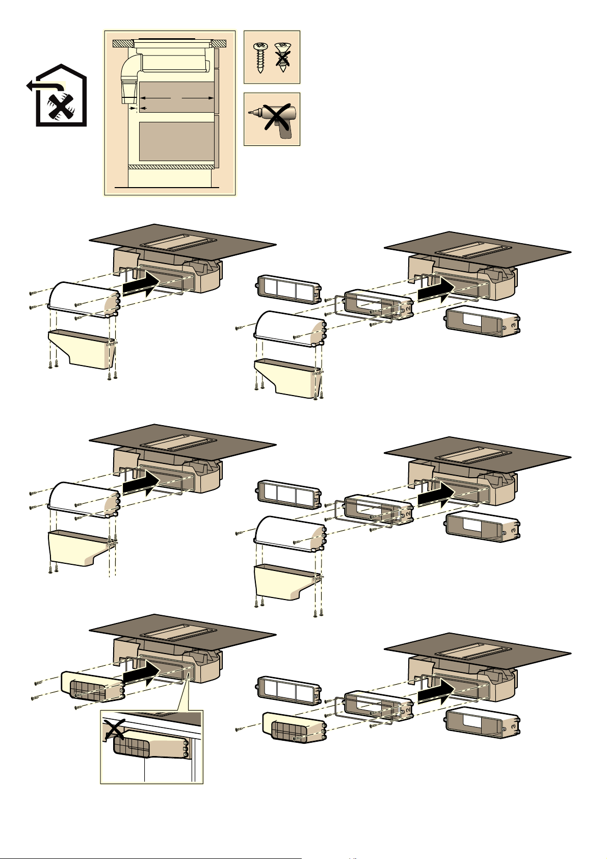
1. Filtermodul am unteren Flachkanalbogen festklipsen oder bei Bedarf festschrauben. (Bild 8a)
16
Hinweis
16
2. Das flexible Verbindungselement am oberen Flachkanalbogen festklipsen.
16
3. Filtermodul und oberen Flachkanalbogen über das flexible Verbindungselement verbinden.
16
Hinweise
16
4. Alle Verschlusselemente am Schubfach öffnen. Schubfach öffnen. (Bild 8b)
16
5. Aktivkohlefilter einsetzen. (Bild 8c)
16
6. Schubfach schließen.
16
7. Alle Verschlusselemente am Schubfach schließen.
16
8. Die erlaubte Tiefe T der Schublade messen, dabei 10 mm Abstand zum Abluftrohr einhalten. (Bild 5)
16
Stromanschluss herstellen
16
Hinweis
16
Anzeige auf Abluftbetrieb oder Umluftbetrieb umstellen
16
Gerät demontieren
16
1. Gerät vom Stromnetz trennen.
16
2. Abluftkanal entfernen oder Umluftverbindungen lösen.
16
3. Gerät von unten herausdrücken.
16
Achtung!
16
Geräteschaden
16
: Important safety information
16
Read these instructions carefully. Only then will you be able to operate your appliance safely and correctly. Retain the instruction manual and installation instructions for future use or for subsequent owners.
16
The appliance can only be used safely if it is correctly installed according to the safety instructions. The installer is responsible for ensuring that the appliance works perfectly at its installation location.
16
Wearers of electronic implants!
16
The manufacturer shall assume no liability for malfunctions or damage resulting from incorrect electrical wiring.
16
Mains cable:The mains cable must only be installed by a qualified professional or by a trained after-sales engineer. The required connection data is located on the rating plate and in the circuit diagrams.
16
Before carrying out any type of work, turn off the electricity.
16
For the installation, observe the currently valid building regulations and the regulations of the local electricity and gas suppliers.
16
When conveying the exhaust air, official and legal regulations (e.g. state building regulations) must be followed.
16
Danger of death!
16
Risk of death!
17
Risk of fire!
17
Risk of injury!
17
Risk of injury!
17
Risk of injury!
17
Danger of suffocation!
17
Do not install this appliance on boats or in vehicles.
17
Hob: flat, horizontal, stable. Follow the hob manufacturer's instructions.
17
If the thickness of the worktop into which the hob is installed does not comply with the specifications, reinforce the worktop using a fire- and water-resistant material until it reaches the minimum thickness. Otherwise, sufficient stability cannot b...
17
Notes
17
General information
17
Exhaust air mode
17
Note
17
Exhaust duct
17
Note
17
Circulating-air mode
17
Note
17
Electrical connection
17
Preparing for installation
18
Appliance dimensions and safety clearances
18
Checking the fitted unit
18
Note
18
Preparing the units
18
1. Make the cut-out in the worktop as shown in the installation drawing. (Fig. 1)
18
Note
18
2. Comply with the minimum clearances when installing over a drawer. (Fig. C)
18
3. Remove the top drawer and attach suitable facing to the kitchen unit.
18
Preparing the unit and appliance for use with air recirculation mode
18
Making a cut-out in the unit
18
1. Make an air outlet in the unit's toe kick.
18
Note
18
2. Remove the kitchen unit's back panel.
18
3. If necessary, remove the upper strip in the unit's back panel.
18
4. On the rear edge of the cut-out in the worktop, determine the centre point and mark this and the two lines vertically downwards on the bottom of the unit. (Fig. 2a)
18
5. Correctly position the fixing plate against the centre lines on the bottom of the unit. (Fig. 2b)
18
6. If drawers are fitted: Close the bottom drawer fully. If the fixing plate disappears too far underneath the drawer, move it towards the rear of the unit. Use the markings on the fixing plate to align it parallel to the centre line. (Fig. 2c)
18
Notes
18
7. If necessary, use the fixing plate to mark out and make the cut- out in the unit bottom. (Fig. 2d)
18
8. After making the cut-outs, remove any shavings.
18
Note
18
Securely screwing on the fixing plate and clipping on the diffusor
18
1. If the clearance between the drawer and the bottom of the unit is sufficient, use plastic screws to secure the fixing plate to the lower flat duct bend from above. (Fig. 3a)
18
Note
18
2. Use wooden screws to secure the fixing plate to the bottom of the unit from above. (Fig. 3a)
18
Note
18
3. Clip the diffusor securely to the lower flat duct bend. (Fig. 3c)
18
Fitting the upper flat duct bend
18
1. If required, choose the extension based on the position of the fixing plate and the unit depth. The longer the extension, the deeper the drawer can be. Use four plastic screws to secure the extension to the hob's outlet opening. (Fig. 4)
18
Note
18
2. Screw the upper flat duct elbow securely to the hob's outlet opening or the extension.
18
Preparing the unit and appliance for use with air extraction mode
18
1. Use four plastic screws to secure the reducing connector or flat duct elbow to the hob's outlet opening or the extension. (Fig. 5)
18
Notes
18
2. Depending on the air extraction system configuration, make a cut-out in the rear panel of the unit for the exhaust air pipe, remove the rear panel of the unit or make a cut-out in the bottom of the unit.
18
3. After making the cut-outs, remove any shavings.
18
Note
18
Installing the appliance
18
: Risk of electric shock!
18
: Risk of injury!
18
Installing the hob
18
1. Attach the mounting rails. (Fig. 6a)
18
2. Place the appliance into the cut-out in the worktop. (Fig. 6b)
18
Connecting the appliance
18
Notes
18
Connecting the air extractor
19
1. Attach the exhaust air pipe to the flat duct elbow or the reducing connector. (Fig. 7)
19
2. Measure the permitted depth T of the drawer – make sure you leave a clearance of 10 mm from the exhaust air pipe. (Fig. 5)
19
3. Connect it to the exhaust air opening.
19
4. Use suitable means to seal the joints.
19
Establishing the connection for the circulated air
19
1. Clip or, if necessary, screw the filter module securely to the lower flat duct elbow. (Fig. 8a)
19
Note
19
2. Clip the flexible connecting element securely to the upper flat duct elbow.
19
3. Use the flexible connecting element to connect the filter module to the upper flat duct elbow.
19
Notes
19
4. Open all of the locks on the drawer. Open the drawer. (Fig. 8b)
19
5. Insert the activated charcoal filter. (Fig. 8c)
19
6. Close the drawer.
19
7. Close all of the locks on the drawer.
19
8. Measure the permitted depth T of the drawer – make sure you leave a clearance of 10 mm from the exhaust air pipe. (Fig. 5)
19
Establishing a connection to the mains
19
Note
19
Switching the display to air extraction mode or air recirculation mode
19
Removing the appliance
19
1. Disconnect the appliance from the power supply.
19
2. Remove the exhaust air duct or disconnect the air recirculation connections.
19
3. Push out the appliance from below.
19
Caution!
19
Damage to the appliance
19
: Importanti avvertenze di sicurezza
19
Leggere attentamente le presenti istruzioni per l'uso. Solo così è possibile utilizzare l'apparecchio in modo sicuro e corretto. Custodire con la massima cura le presenti istruzioni per l'uso e il montaggio in caso di un utilizzo futuro o cessione ...
19
La sicurezza di utilizzo è garantita solo in caso di installazione secondo le regole di buona tecnica riportate nelle istruzioni di montaggio. L'installatore è responsabile del corretto funzionamento nel luogo di installazione.
19
Portatori di impianti elettronici!
19
Il costruttore non si assume alcuna responsabilità per eventuali guasti o danni riconducibili a un'installazione elettrica difettosa.
19
Cavo di rete:il cavo di rete deve essere installato esclusivamente da personale specializzato e autorizzato o da un tecnico del servizio di assistenza clienti debitamente formato. I dati per il collegamento necessari sono reperibili sulla targhetta d...
19
Staccare l'alimentazione di corrente prima di procedere ad ogni tipo di intervento.
19
Per l’installazione è necessario rispettare le disposizioni in materia di edilizia attualmente in vigore e le norme del fornitore locale di elettricità e gas.
19
Per quanto concerne la conduzione dell'aria esausta è necessario rispettare le normative di legge ufficiali (ad es. normative urbanistiche provinciali).
19
Pericolo di morte!
19
Pericolo di morte!
19
Pericolo di incendio!
19
Pericolo di lesioni!
20
Pericolo di lesioni!
20
Pericolo di lesioni!
20
Pericolo di soffocamento!
20
Questo apparecchio non deve essere installato su barche o veicoli.
20
Piano di lavoro: piatto, orizzontale e stabile. Attenersi alle istruzioni del fabbricante del piano di lavoro.
20
Se lo spessore del piano di lavoro all'interno del quale viene incassato il piano di cottura non corrisponde ai requisiti richiesti, rinforzare il piano di lavoro con materiale refrattario e resistente all'acqua fino a raggiungere lo spessore minimo ...
20
Avvertenze
20
Indicazioni generali
20
Modalità aspirazione
20
Avvertenza
20
Scarico dell'aria
20
Avvertenza
20
Funzionamento a ricircolo d'aria
20
Avvertenza
20
Collegamento elettrico
20
Preparazione dell'installazione
20
Dimensioni dell'apparecchio e distanze di sicurezza
20
Controllare il mobile
20
Avvertenza
20
Preparazione dei mobili
20
1. Realizzare l'apertura nel piano di lavoro secondo il disegno di montaggio. (fig. 1)
20
Avvertenza
21
2. In caso di montaggio sopra uno scomparto scorrevole, rispettare le distanze indicate. (fig. C)
21
3. Rimuovere lo scomparto scorrevole superiore e sul mobile montare una copertura adeguata.
21
Preparazione del mobile e dell'apparecchio per il funzionamento ad aria di ricircolo
21
Praticare il foro di incasso del mobile
21
1. Realizzare uno scarico per l'aria nello zoccolo del mobile.
21
Avvertenza
21
2. Rimuovere la parete posteriore del mobile.
21
3. Se necessario rimuovere il listello superiore sulla parete posteriore del mobile.
21
4. Sul bordo superiore del foro d'incasso del piano di lavoro determinare il punto centrale e segnare le due linee verticalmente verso il basso sul fondo del mobile. (fig. 2a)
21
5. Allineare la lamiera di fissaggio sul fondo del mobile basandosi sulle linee centrali. (fig. 2b)
21
6. Se ci sono cassetti: chiudere completamente il cassetto più in basso. Se la lamiera di fissaggio scompare eccessivamente sotto al cassetto, spingerla verso il lato posteriore del mobile. Con l'aiuto delle marcature nella lamiera di fissaggio alli...
21
Avvertenze
21
7. Se necessario segnare e realizzare un'apertura nel fondo del mobile con l'aiuto della lamiera di fissaggio. (fig. 2d)
21
8. Rimuovere i trucioli dopo i lavori di taglio.
21
Avvertenza
21
Avvitare la lamiera di fissaggio e fissare con clips il diffusore
21
1. Se la distanza tra il cassetto e il fondo del mobile è sufficiente, avvitare la lamiera di fissaggio con viti in plastica dall'alto e sulla curva inferiore del canale piatto. (fig. 3a)
21
Avvertenza
21
2. Avvitare la lamiera di fissaggio con viti per legno dall'alto e sul fondo del mobile. (fig. 3a)
21
Avvertenza
21
3. Fissare con clip il diffusore sulla curva inferiore del canale piatto. (fig. 3c)
21
Montaggio della curva del canale piatto
21
1. Se necessario scegliere la prolunga in funzione della posizione della lamiera di fissaggio e della profondità del mobile. Più è lunga la prolunga, più profondo può essere il cassetto. Avvitare la prolunga con quattro viti in plastica sull'ape...
21
Avvertenza
21
2. Avvitare la curva del canale piatto sull'apertura di scarico del piano cottura o sulla prolunga.
21
Preparazione del mobile e dell'apparecchio per la modalità di aspirazione
21
1. Avvitare i bocchettoni di riduzione o la curva del canale piatto con quattro viti in plastica sull'apertura di scarico del piano cottura o sulla prolunga. (fig. 5)
21
Avvertenze
21
2. In funzione della configurazione dello scarico d'aria per il tubo di scarico praticare un'apertura nella parete posteriore del mobile, rimuovere la parete posteriore o praticare un'apertura nel fondo del mobile.
21
3. Rimuovere i trucioli dopo i lavori di taglio.
21
Avvertenza
21
Montaggio dell’apparecchio
21
: Pericolo di scossa elettrica!
21
: Pericolo di lesioni!
21
Inserimento del piano di cottura
21
1. Montare le guide di supporto. (fig. 6a)
21
2. Inserire l'apparecchio nel foro d'incasso del piano di lavoro. (fig. 6b)
21
Collegare l'apparecchio
21
Avvertenze
21
Realizzazione del collegamento allo scarico dell'aria
21
1. Fissare il tubo di scarico sulla curva del canale piatto o al manicotto di riduzione. (fig. 7)
21
2. Misurare la profondità T consentita del cassetto, rispettando 10 mm di distanza dal tubo di scarico. (fig. 5)
21
3. Realizzare il collegamento all'apertura per lo scarico dell'aria.
21
4. Sigillare ermeticamente i punti di collegamento.
21
Realizzazione del collegamento di ricircolo d'aria
21
1. Fissare con le clip il modulo filtro sulla curva inferiore del canale piatto o, se necessario, avvitarlo. (fig. 8a)
21
Avvertenza
21
2. Fissare con clip l'elemento di collegamento flessibile sulla curva superiore del canale piatto.
21
3. Collegare il modulo filtro e la curva superiore del canale piatto sull'elemento di collegamento flessibile.
21
Avvertenze
21
4. Aprire tutti gli elementi di chiusura sullo scomparto scorrevole. Aprire lo scomparto scorrevole. (fig. 8b)
21
5. Inserire il filtro a carbone attivo. (fig. 8c)
21
6. Chiudere lo scomparto scorrevole.
21
7. Chiudere tutti gli elementi di chiusura sullo scomparto scorrevole.
21
8. Misurare la profondità T consentita del cassetto, rispettando 10 mm di distanza dal tubo di scarico. (fig. 5)
21
Realizzazione del collegamento elettrico
22
Avvertenza
22
Passaggio dell'indicatore alla modalità aspirazione a ricircolo o al funzionamento ad aria di ricircolo
22
Smontaggio dell'apparecchio
22
1. Staccare l'apparecchio dalla rete elettrica.
22
2. Rimuovere il canale di scarico o i collegamenti di ricircolo d'aria.
22
3. Estrarre l'apparecchio spingendolo dal basso.
22
Attenzione!
22
Danni all'apparecchio
22
: Belangrijke veiligheidsvoorschriften
22
Lees deze gebruiksaanwijzing zorgvuldig door. Alleen dan kunt u uw apparaat goed en veilig bedienen. Bewaar de gebruiksaanwijzing voor later gebruik of om door te geven aan een volgende eigenaar.
22
De veiligheid is alleen gewaarborgd bij een deskundige montage volgens de montagehandleiding. De installateur is verantwoordelijk voor een goede werking op de plaats van opstelling.
22
Dragers van elektronische implantaten!
22
De fabrikant is niet verantwoordelijk voor bedrijfsstoringen of mogelijke schade als gevolg van een onjuiste elektrische installatie.
22
Voedingskabel:De voedingskabel mag alleen door een erkend vakman of een geschoolde technicus van de klantenservice worden geïnstalleerd. De vereiste aansluitgegevens bevinden zich op het typeplaatje en in de aansluitschema's.
22
Vóór alle werkzaamheden aan het apparaat dient het apparaat spanningsvrij te worden gemaakt.
22
Bij de installatie moeten de actuele geldige bouwvoorschriften en de voorschriften van de plaatselijke stroom- en gasleverancier in acht worden genomen.
22
Ten aanzien van de afvoerlucht dienen de overheids- en wettelijke voorschriften (zoals lokale bouwverordeningen) in acht te worden genomen.
22
Levensgevaar!
22
Levensgevaar!
22
Brandgevaar!
22
Risico van letsel!
22
Risico van letsel!
22
Gevaar voor letsel!
22
Verstikkingsgevaar!
22
Dit toestel niet bij boten of vaartuigen inbouwen.
22
Werkblad: vlak, horizontaal, stabiel. Volg de instructies van de fabrikant van het werkblad op.
22
Wanneer de dikte van het werkblad waarin de kookplaat wordt gemonteerd, niet aan de vereiste maat voldoet, moet het werkblad met hitte- en waterbestendig materiaal worden verstevigd tot de aanbevolen minimale dikte is bereikt. Anders kan geen voldoen...
22
Aanwijzingen
23
Algemene aanwijzingen
23
Gebruik met afvoerlucht
23
Aanwijzing
23
Luchtafvoer
23
Aanwijzing
23
Gebruik met circulatielucht
23
Aanwijzing
23
Elektrische aansluiting
23
Installatie voorbereiden
23
Apparaatafmetingen en veiligheidsafstanden
23
Meubel controleren
23
Aanwijzing
23
Meubel voorbereiden
23
1. Maak de uitsnijding in het werkblad aan de hand van de inbouwtekening. (Afb. 1)
23
Aanwijzing
23
2. Houd bij inbouw boven een lade minimale afstanden aan. (Afb. C)
23
3. De bovenste lade verwijderen en een passende afscherming op het meubel aanbrengen.
23
Meubel en apparaat voorbereiden voor luchtcirculatie
23
Meubeluitsnijding maken
23
1. In de voorste plint van het meubel een luchtuitlaat maken.
23
Aanwijzing
23
2. Achterkant van het meubel verwijderen.
23
3. De bovenste lijst aan de achterkant van het meubel zo nodig verwijderen.
23
4. Bepaal het middelpunt op de achterste rand van de werkbladuitsnijding en geef dit en de beide lijnen loodrecht naar beneden weer op de bodem van het meubel. (Afb. 2a)
23
5. Montageplaat uitlijnen op de middellijn van de bodem van het meubel. (Afb. 2b)
23
6. Bij laden: onderste lade volledig sluiten. Verdwijnt de montageplaat te ver onder de lade, verplaats hem dan in de richting van de achterkant van het meubel. Lijn hem met behulp van de markeringen op de montageplaat parallel aan de middellijn uit....
24
Aanwijzingen
24
7. Zo nodig met behulp van de montageplaat in de bodem van het meubel een uitsnijding tekenen en maken. (Afb. 2d)
24
8. Na uitsnijwerkzaamheden de spaanders verwijderen.
24
Aanwijzing
24
Montageplaat en diffusor vastclipsen
24
1. Wanneer er voldoende afstand is tussen de lade en de bodem van het meubel de montageplaat met kunststofschroeven van bovenaf vastschroeven aan de onderste bocht van de platte buis. (Afb. 3a)
24
Aanwijzing
24
2. Montageplaat met houtschroeven van boven aan de bodem van het meubel bevestigen. (Afb. 3a)
24
Aanwijzing
24
3. Diffusor vastclipsen aan de onderste bocht van de platte buis. (Afb. 3c)
24
Bovenste bocht van de platte buis monteren
24
1. De verlenging zo nodig kiezen afhankelijk van de positie van de montageplaat en de meubeldiepte. Hoe langer de verlenging, hoe dieper de lade kan zijn. De verlenging met vier kunststof vastschroeven aan de afzuigopening van de kookplaat. (Afb. 4)
24
Aanwijzing
24
2. De bovenste bocht van de platte buis vastschroeven aan de afzuigopening van de kookplaat of aan de verlenging.
24
Meubel en apparaat voorbereiden voor luchtafvoer
24
1. Verloopstuk of de bocht van de platte buis met vier kunststof schroeven aan de uitlaatopening van de kookplaat of aan de verlenging vastschroeven. (Afb. 5)
24
Aanwijzingen
24
2. Afhankelijk van de configuratie van de luchtafvoer een uitsnijding voor de afvoerbuis maken in de achterste meubelwand, de achterkant van het meubel verwijderen of een uitsnijding in de bodem van het meubel maken.
24
3. Na uitsnijwerkzaamheden de spaanders verwijderen.
24
Aanwijzing
24
Apparaat monteren
24
: Gevaar van een elektrische schok!
24
: Risico van letsel!
24
Kookplaat inbrengen
24
1. Bevestigingsrails aanbrengen. (Afb. 6a)
24
2. Het apparaat in de uitsnijding van het werkblad plaatsen. (Afb. 6b)
24
Apparaat aansluiten
24
Aanwijzingen
24
Luchtafvoerverbinding maken
24
1. Luchtafvoerbuis bevestigen aan de bocht van de platte buis of het verloopstuk. (Afb. 7)
24
2. De toegestane diepte T van de lade meten, hierbij 10 mm afstand tot de afvoerbuis in acht nemen. (Afb. 5)
24
3. Verbinding maken met de luchtafvoeropening.
24
4. Verbindingspunten goed afdichten.
24
Circulatieluchtverbinding maken
24
1. Filtermodule vastclipsen aan de onderste bocht van de platte buis of zo nodig vastschroeven. (Afb. 8a)
24
Aanwijzing
24
2. Het flexibele verbindingselement aan de bovenste bocht van de platte buis vastclipsen.
24
3. Filtermodule en de bovenste bocht van de platte buis verbinden via het flexibele verbindingselement.
24
Aanwijzingen
24
4. Alle sluitingselementen van de lade openen. Lade openen. (Afb. 8b)
24
5. Actieve koolfilter inbrengen. (Afb. 8c)
24
6. Lade sluiten.
24
7. Alle sluitingselementen van de lade sluiten.
24
8. De toegestane diepte T van de lade meten, hierbij 10 mm afstand tot de afvoerbuis in acht nemen. (Afb. 5)
24
Stroom aansluiten
24
Aanwijzing
24
Display omschakelen naar luchtafvoer of luchtcirculatie
24
Apparaat demonteren
24
1. Apparaat loskoppelen van het stroomnet.
24
2. Luchtafvoerkanaal verwijderen of luchtcirculatieverbindingen loskoppelen.
24
3. Het apparaat van onderuit naar buiten drukken.
24
Attentie!
24
Schade aan het apparaat
24
: Précautions de sécurité importantes
25
Lire attentivement ce manuel. Ce n'est qu'alors que vous pourrez utiliser votre appareil correctement et en toute sécurité. Conserver la notice d'utilisation et de montage pour un usage ultérieur ou pour le propriétaire suivant.
25
La sécurité de l’appareil à l’usage est garantie s’il a été encastré conformément à la notice de montage. Le monteur est responsable du fonctionnement correct sur le lieu où l'appareil est installé.
25
Porteurs d'implants électroniques !
25
Le fabricant décline toute responsabilité pour des dérangements ou dommages éventuels dus à une installation électrique incorrecte.
25
Câble secteur :le câble secteur doit uniquement être installé par un personnel autorisé ou par un technicien qualifié du service après-vente. Les valeurs de raccordement requises se trouvent sur la plaque signalétique et sur les schémas de c...
25
Avant tout travail, couper l'alimentation électrique.
25
L’installation doit avoir lieu en respectant les prescriptions actuellement en vigueur dans le bâtiment, ainsi que les prescriptions publiées par les compagnies distributrices d’électricité et de gaz.
25
Le mode d'évacuation de l'air vicié devra être conforme aux arrêtés municipaux, préfectoraux, et aux prescriptions légales (par ex. aux ordonnances publiques applicables au bâtiment).
25
Danger de mort !
25
Danger de mort !
25
Risque d'incendie !
25
Risque de blessure !
25
Risque de blessure !
25
Risque de blessures !
25
Risque d'asphyxie !
25
Ne pas installer cet appareil sur des bateaux ou dans des véhicules.
25
Plan de travail : plat, horizontal, stable. Respectez les instructions du fabricant du plan de travail.
25
Si l'épaisseur du plan de travail monté dans la table de cuisson ne correspond pas aux indications, renforcer le plan de travail avec un matériau imperméable et réfractaire jusqu'à atteindre l'épaisseur minimale requise. Sinon aucune stabilit...
25
Remarques
25
Consignes générales
25
Mode Évacuation de l’air
25
Remarque
25
Conduit d'évacuation
25
Remarque
25
Fonctionnement en mode recyclage
26
Remarque
26
Branchement électrique
26
Préparer l’installation
26
Dimensions de l'appareil et distances de sécurité
26
Vérifier l'état du meuble
26
Remarque
26
Préparation du meuble
26
1. Réalisez la découpe dans le plan de travail conformément au croquis d'installation. (fig. 1)
26
Remarque
26
2. Observez les distances minimales en cas de montage au-dessus d'un tiroir. (fig. C)
26
3. Retirez le tiroir supérieur et mettez en place un recouvrement approprié sur le meuble.
26
Préparation du meuble et de l'appareil pour le mode Recyclage d'air
26
Réalisation de la découpe dans le meuble
26
1. Créez une sortie d'air dans la plinthe avant du meuble.
26
Remarque
26
2. Retirez la paroi arrière du meuble.
26
3. Retirez si nécessaire la baguette supérieure de la paroi arrière du meuble.
26
4. Déterminez le centre du bord arrière de la découpe du plan de travail et reportez celui-ci ainsi que les deux lignes verticalement vers le bas, sur le fond inférieur du meuble. (fig. 2a)
26
5. Orientez la tôle de fixation en fonction des lignes médianes sur le fond inférieur du meuble. (fig. 2b)
26
6. Pour les tiroirs : fermez le tiroir inférieur. Si la tôle de fixation rentre trop loin sous le tiroir, déplacez celle-ci en direction de la paroi arrière. À l'aide des marquages de la tôle de fixation, positionnez celle-ci de façon à ce qu...
26
Remarques
26
7. Si nécessaire, tracez les lignes de découpe à l'aide de la tôle de fixation sur le fond inférieur du meuble. (fig. 2d)
26
8. Enlevez les copeaux après les travaux de découpe.
26
Remarque
26
Vissage de le tôle de fixation et clipsage du diffuseur
27
1. Si la distance entre le tiroir et le fond du meuble est suffisante, fixez la tôle de fixation à l'aide de vis pour plastique depuis le haut au coude inférieur de gaine plate. (fig. 3a)
27
Remarque
27
2. Fixez la tôle de fixation à l'aide de vis à bois depuis le haut au fond inférieur du meuble. (fig. 3a)
27
Remarque
27
3. Clipsez le diffuseur au coude inférieur de la gaine plate. (fig. 3c)
27
Montage du coude supérieur de gaine plate
27
1. Choisissez, si nécessaire, la rallonge en fonction de la position de la tôle de fixation et de la profondeur du meuble. Plus la rallonge est longue, plus le tiroir peut être profond. Fixez la rallonge à l'aide de quatre vis pour plastique au n...
27
Remarque
27
2. Fixez le coude supérieur de gaine plate à l'aide de quatre vis pour plastique au niveau de l'ouverture de sortie de la table de cuisson ou de la rallonge.
27
Préparation du meuble et de l'appareil pour le mode Évacuation extérieure
27
1. Fixez le manchon réducteur ou le coude de la gaine plate à l'aide de quatre vis pour plastique au niveau de l'ouverture de sortie de la table de cuisson ou de la rallonge. (fig. 5)
27
Remarques
27
2. En fonction de la configuration du conduit d'évacuation, réalisez une découpe dans la paroi arrière du meuble, retirez la paroi arrière du meuble ou réalisez une découpe dans le fond inférieur du meuble.
27
3. Retirez les copeaux après les travaux de découpe.
27
Remarque
27
Monter l'appareil
27
: Risque de choc électrique !
27
: Risque de blessure !
27
Mise en place de la table de cuisson
27
1. Montez les barrettes de fixation. (fig. 6a)
27
2. Installez l'appareil dans la découpe du plan de travail. (fig. 6b)
27
Brancher l'appareil
27
Remarques
27
Réaliser le raccordement de l'évacuation de l'air
27
1. Fixez le conduit d’évacuation contre le coude de gaine plate ou le manchon réducteur. (fig. 7)
27
2. Mesurez la profondeur P autorisée du tiroir, ce faisant respectez un écart de 10 mm par rapport au conduit d'évacuation. (fig. 5)
27
3. Effectuez la jonction vers l'orifice d'évacuation d'air.
27
4. Étanchez les zones de jonction de façon appropriée.
27
Réaliser le raccordement de l'air de circulation
27
1. Clipsez le module de filtre au coude inférieur de la gaine plate ou fixez-le à l'aide de vis, si nécessaire. (fig. 8a)
27
Remarque
27
2. Clipsez l'élément de fixation flexible au coude supérieur de la gaine plate.
27
3. Reliez le module de filtre et le coude supérieur de la gaine plate à l'aide de l'élément de fixation flexible.
27
Remarques
27
4. Ouvrez tous les volets de fermeture sur le tiroir. Ouvrez le tiroir. (fig. 8b)
27
5. Mettez le filtre à charbon actif en place. (fig. 8c)
27
6. Fermez le tiroir.
27
7. Fermez tous les volets de fermeture sur le tiroir.
27
8. Mesurez la profondeur P autorisée du tiroir, ce faisant respectez un écart de 10 mm par rapport au conduit d'évacuation. (fig. 5)
27
Réaliser le raccordement électrique
27
Remarque
27
Commutation de l’affichage sur le mode Évacuation extérieure ou le mode Recyclage d'air
27
Démonter l'appareil
27
1. Débrancher l’appareil du réseau électrique.
27
2. Détachez le conduit d'évacuation ou les conduits de recyclage d'air.
27
3. Faites sortir l'appareil en le poussant par le bas.
27
Attention !
27
Risques de détérioration de l'appareil
27
Search:
×
Search