Operating Instructions
Manual de instrucciones
ES
US
Owner’s Record
The model and serial numbers are located on the bottom of the unit.
Record the serial number in the space provided below.
Refer to these numbers whenever you call upon your Sony dealer regarding this product.
Model No. MEX-BT3700U Serial No.
To cancel the demonstration (DEMO) display, see page 7.
Para cancelar la pantalla de demostración (DEMO), consulte la página 7.
4-125-655-11 (1)
MEX-BT3700U
©2009 Sony Corporation
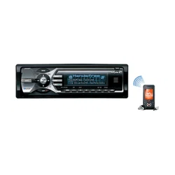
Bluetooth
®
Audio System
2
Warning
Note on the lithium battery
Do not expose the battery to excessive heat such as
direct sunlight, fire or the like.
The Bluetooth word mark and logos are owned
by the Bluetooth SIG, Inc. and any use of such
marks by Sony Corporation is under license.
Other trademarks and trade names are those of
their respective owners.
ZAPPIN is a trademark of Sony Corporation.
iPod is a trademark of Apple Inc., registered in
the U.S. and other countries.
iPhone is a trademark of Apple Inc.
Be sure to install this unit in the dashboard of
the car for safety. For installation and
connections, see the supplied installation/
connections manual.
This equipment has been tested and found to
comply with the limits for a Class B digital
device, pursuant to Part 15 of the FCC Rules.
These limits are designed to provide reasonable
protection against harmful interference in a
residential installation. This equipment
generates, uses, and can radiate radio frequency
energy and, if not installed and used in
accordance with the instructions, may cause
harmful interference to radio communications.
However, there is no guarantee that interference
will not occur in a particular installation. If this
equipment does cause harmful interference to
radio or television reception, which can be
determined by turning the equipment off and on,
the user is encouraged to try to correct the
interference by one or more of the following
measures:
–
Reorient or relocate the receiving antenna.
–
Increase the separation between the equipment
and receiver.
–
Connect the equipment into an outlet on a
circuit different from that to which the receiver
is connected.
–
Consult the dealer or an experienced radio/TV
technician for help.
This transmitter must not be co-located or
operated in conjunction with any other antenna
or transmitter.
This equipment complies with FCC and IC
radiation exposure limits set forth for
uncontrolled equipment and meets the FCC
radio frequency (RF) Exposure Guidelines in
Supplement C to OET65 and RSS-102 of the
IC radio frequency (RF) Exposure rules. This
equipment has very low levels of RF energy
that it deemed to comply without maximum
permissive exposure evaluation (MPE). But it
is desirable that it should be installed and
operated with at least 20 cm and more between
the radiator and person's body (excluding
extremities: hands, wrists, feet and ankles).
You are cautioned that any changes or
modifications not expressly approved in this
manual could void your authority to operate this
equipment.
The use of optical instruments with this produc
t
will increase eye hazard.
CAUTION
For the state of california, USA only
Perchlorate Material – special handling may apply,
See www.dtsc.ca.gov/hazardouswaste/perchlorate
Perchlorate Material: Lithium battery contains
perchlorate
Windows Media, and the
Windows logo are trademarks
or registered trademarks of
Microsoft Corporation in the
United States and/or other countries.
MPEG Layer-3 audio coding technology and
patents licensed from Fraunhofer IIS and Thomson.
This product is protected by certain intellectual
property rights of Microsoft Corporation. Use or
distribution of such technology outside of this
product is prohibited without a license from
Microsoft or an authorized Microsoft subsidiary.
3
Warning if your car’s ignition has no
ACC position
Be sure to set the Auto Off function (page 20).
The unit will shut off completely and
automatically in the set time after the unit is
turned off, which prevents battery drain.
If you do not set the Auto Off function, press
and hold (OFF) until the display disappears
each time you turn the ignition off.
Content providers are using the digital rights
management technology for Windows Media
contained in this device (“WM-DRM”) to protect
the integrity of their content (“Secure Content”) so
that their intellectual property, including copyright,
in such content is not misappropriated.
This device uses WM-DRM software to play
Secure Content (“WM-DRM Software”). If the
security of the WM-DRM Software in this device
has been compromised, owners of Secure Content
(“Secure Content Owners”) may request that
Microsoft revoke the WM-DRM Software’s right
to acquire new licenses to copy, display and/or
play Secure Content. Revocation does not alter the
WM-DRM Software’s ability to play unprotected
content. A list of revoked WM-DRM Software is
sent to your device whenever you download a
license for Secure Content from the Internet or
from a PC. Microsoft may, in conjunction with
such license, also download revocation lists onto
your device on behalf of Secure Content Owners.
The “HD Radio Ready” logo indicates that this
product will control a Sony HD Radio
TM
tuner
(sold separately).
For HD Radio
TM
tuner operation, please refer to
the HD Radio
TM
tuner Operating Instructions.
HD Radio
TM
and the HD Radio Ready logo are
proprietary trademarks of iBiquity Digital Corp.
The “SAT Radio Ready”
logo indicates that this
product will control a
satellite radio tuner module
(sold separately). Please see your nearest
authorized Sony dealer for details on the
satellite radio tuner module.
“SAT Radio,” “SAT Radio Ready,” the SAT
Radio and SAT Radio Ready logos and all
related marks are trademarks of Sirius Satellite
Radio Inc. and XM Satellite Radio Inc.

4
Table of Contents
Getting Started
Playable discs on this unit . . . . . . . . . . . . . . . . . 6
Notes on Bluetooth . . . . . . . . . . . . . . . . . . . . . . 6
Resetting the unit. . . . . . . . . . . . . . . . . . . . . . . . 6
Canceling the DEMO mode . . . . . . . . . . . . . . . 7
Preparing the card remote commander . . . . . . . 7
Setting the clock . . . . . . . . . . . . . . . . . . . . . . . . 7
Detaching the front panel . . . . . . . . . . . . . . . . . 7
Attaching the front panel . . . . . . . . . . . . . . . 7
Location of controls and basic
operations
Main unit. . . . . . . . . . . . . . . . . . . . . . . . . . . . 8
Card remote commander RM-X304 . . . . . . 10
Searching for a track . . . . . . . . . . . . . . . . . . . . 11
Searching a track by name
— Quick-BrowZer . . . . . . . . . . . . . . . . . . . 11
Searching a track by listening to track passages
— ZAPPIN™ . . . . . . . . . . . . . . . . . . . . . . . 12
Radio
Storing and receiving stations . . . . . . . . . . . . . 12
Storing automatically — BTM . . . . . . . . . . 12
Storing manually. . . . . . . . . . . . . . . . . . . . . 12
Receiving the stored stations . . . . . . . . . . . 12
Tuning automatically . . . . . . . . . . . . . . . . . 12
CD
Display items . . . . . . . . . . . . . . . . . . . . . . . 13
Repeat and shuffle play. . . . . . . . . . . . . . . . 13
USB devices
Playing back a USB device . . . . . . . . . . . . . . . 13
Display items . . . . . . . . . . . . . . . . . . . . . . . 14
Repeat and shuffle play. . . . . . . . . . . . . . . . 14
iPod
Playing back iPod . . . . . . . . . . . . . . . . . . . . . . 14
Display items . . . . . . . . . . . . . . . . . . . . . . . 15
Setting the play mode . . . . . . . . . . . . . . . . . . . 15
Repeat and shuffle play. . . . . . . . . . . . . . . . 15
Operating an iPod directly
— Passenger control . . . . . . . . . . . . . . . . . . . . 16
Bluetooth (Handsfree calling and
Music streaming)
Bluetooth operations. . . . . . . . . . . . . . . . . . . . 16
Pairing. . . . . . . . . . . . . . . . . . . . . . . . . . . . . . . 16
About Bluetooth icons . . . . . . . . . . . . . . . . 17
Connection . . . . . . . . . . . . . . . . . . . . . . . . . . . 17
To switch the Bluetooth signal output of this
unit to on . . . . . . . . . . . . . . . . . . . . . . . . . . 17
Connecting a cellular phone. . . . . . . . . . . . 17
Connecting an audio device . . . . . . . . . . . . 18
Handsfree calling . . . . . . . . . . . . . . . . . . . . . . 18
Receiving calls . . . . . . . . . . . . . . . . . . . . . . 18
Making calls . . . . . . . . . . . . . . . . . . . . . . . . 18
Call transfer . . . . . . . . . . . . . . . . . . . . . . . . 18
Voice Dial Activation . . . . . . . . . . . . . . . . 18
Music streaming . . . . . . . . . . . . . . . . . . . . . . . 19
Listening to music from an audio
device . . . . . . . . . . . . . . . . . . . . . . . . . . . . . 19
Operating an audio device with this
unit . . . . . . . . . . . . . . . . . . . . . . . . . . . . . . . 19
Deleting registration of all paired
devices . . . . . . . . . . . . . . . . . . . . . . . . . . . . . . 19
Other functions
Changing the sound settings . . . . . . . . . . . . . . 20
Adjusting the sound characteristics . . . . . . 20
Customizing the equalizer curve
— EQ3 . . . . . . . . . . . . . . . . . . . . . . . . . . . . 20
Adjusting setup items — SET . . . . . . . . . . . . 20
Using optional equipment. . . . . . . . . . . . . . . . 21
Auxiliary audio equipment. . . . . . . . . . . . . 21
CD changer. . . . . . . . . . . . . . . . . . . . . . . . . 22
Rotary commander RM-X4S . . . . . . . . . . . 22
External microphone XA-MC10 . . . . . . . . 23
Additional Information
Precautions . . . . . . . . . . . . . . . . . . . . . . . . . . . 23
Notes on discs . . . . . . . . . . . . . . . . . . . . . . 23
Playback order of MP3/WMA/AAC
files. . . . . . . . . . . . . . . . . . . . . . . . . . . . . . . 24
About iPod . . . . . . . . . . . . . . . . . . . . . . . . . 24
About Bluetooth function. . . . . . . . . . . . . . 24
Maintenance . . . . . . . . . . . . . . . . . . . . . . . . . . 25
Removing the unit. . . . . . . . . . . . . . . . . . . . . . 26
Specifications . . . . . . . . . . . . . . . . . . . . . . . . . 26
Troubleshooting . . . . . . . . . . . . . . . . . . . . . . . 27
Error displays/Messages. . . . . . . . . . . . . . . 29
5
Support site
If you have any questions or for the latest support information on this
product, please visit the web site below:
http://esupport.sony.com
http://www.xplodsony.com/
Provides information on:
• Models and manufacturers of compatible digital audio players
• Supported MP3/WMA/AAC files
• Models and manufacturers of compatible cellular phones and the FAQ
about Bluetooth function
6
Getting Started
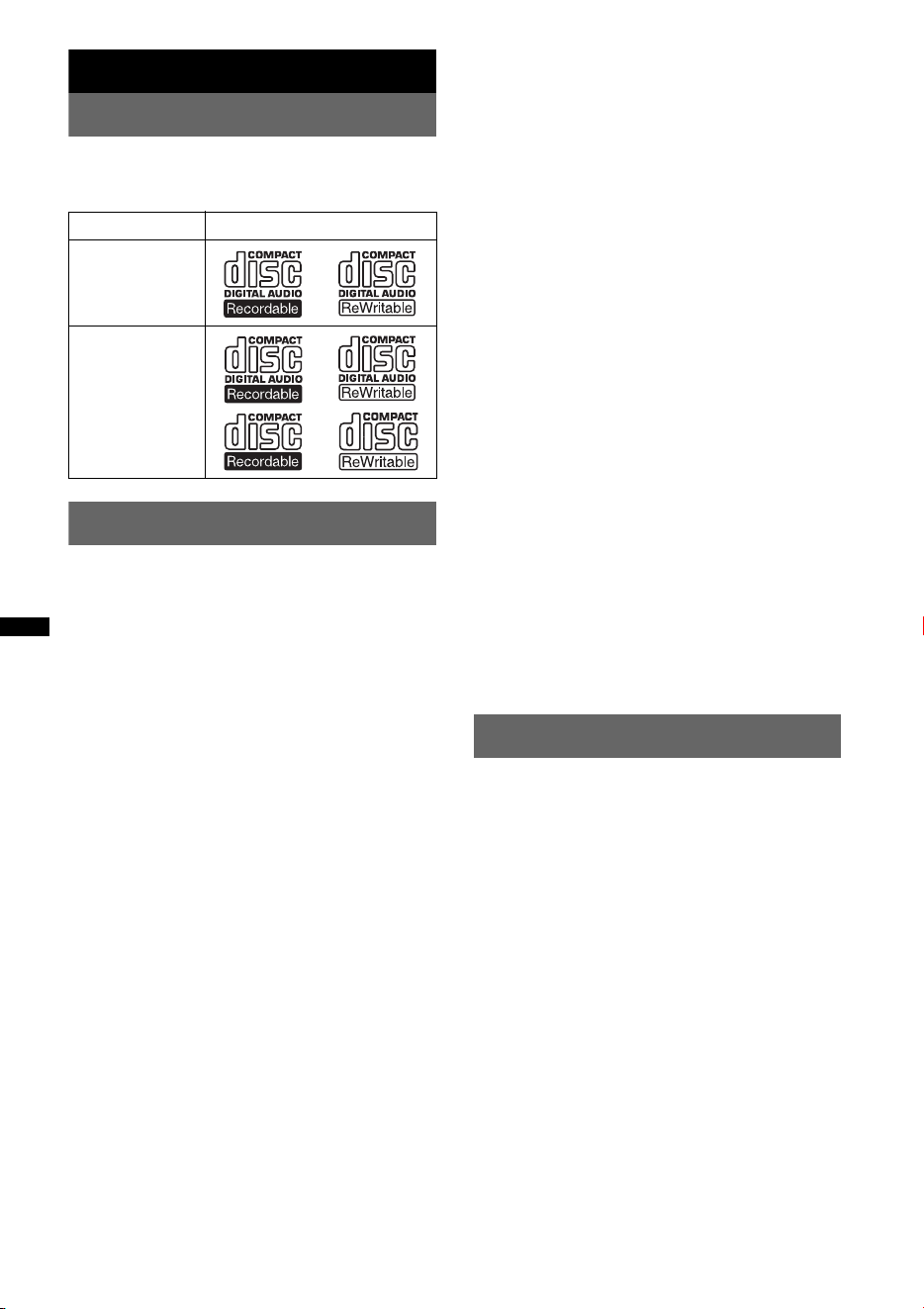
Playable discs on this unit
This unit can play CD-DA (also containing CD
TEXT) and CD-R/CD-RW (MP3/WMA/AAC
files (page 23)).
Notes on Bluetooth
Caution
IN NO EVENT SHALL SONY BE LIABLE FOR
ANY INCIDENTAL, INDIRECT OR
CONSEQUENTIAL DAMAGES OR OTHER
DAMAGES INCLUDING, WITHOUT
LIMITATION, LOSS OF PROFITS, LOSS OF
REVENUE, LOSS OF DATA, LOSS OF USE OF
THE PRODUCT OR ANY ASSOCIATED
EQUIPMENT, DOWNTIME, AND
PURCHASER’S TIME RELATED TO OR
ARISING OUT OF THE USE OF THIS
PRODUCT, ITS HARDWARE AND/OR ITS
SOFTWARE.
IMPORTANT NOTICE!
Safe and efficient use
Changes or modifications to this unit not expressly
approved by Sony may void the user’s authority to
operate the equipment.
Please check for exceptions, due to national
requirement or limitations, in usage of Bluetooth
equipment before using this product.
Driving
Check the laws and regulations on the use of cellular
phones and handsfree equipment in the areas where
you drive.
Always give full attention to driving and pull off the
road and park before making or answering a call if
driving conditions so require.
Connecting to other devices
When connecting to any other device, please read its
user guide for detailed safety instructions.
Radio frequency exposure
RF signals may affect improperly installed or
inadequately shielded electronic systems in cars,
such as electronic fuel injection systems, electronic
antiskid (antilock) braking systems, electronic speed
control systems or air bag systems. For installation
or service of this device, please consult with the
manufacturer or its representative of your car. Faulty
installation or service may be dangerous and may
invalidate any warranty that may apply to this
device.
Consult with the manufacturer of your car to ensure
that the use of your cellular phone in the car will not
affect its electronic system.
Check regularly that all wireless device equipment
in your car is mounted and operating properly.
Emergency calls
This Bluetooth car handsfree and the electronic
device connected to the handsfree operate using
radio signals, cellular, and landline networks as well
as user-programmed function, which cannot
guarantee connection under all conditions.
Therefore do not rely solely upon any electronic
device for essential communications (such as
medical emergencies).
Remember, in order to make or receive calls, the
handsfree and the electronic device connected to the
handsfree must be switched on in a service area with
adequate cellular signal strength.
Emergency calls may not be possible on all cellular
phone networks or when certain network services
and/or phone features are in use.
Check with your local service provider.
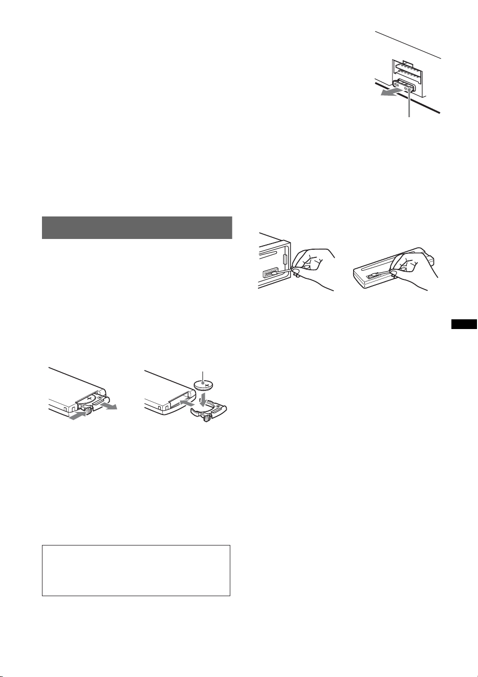
Resetting the unit
Before operating the unit for the first time, or
after replacing the car battery or changing the
connections, you must reset the unit.
Detach the front panel (page 7) and press the
RESET button (page 8) with a pointed object,
such as a ball-point pen.
Note
Pressing the RESET button will erase the clock setting
and some stored contents.
Type of discs Label on the disc
CD-DA
MP3
WMA
AAC
7
Canceling the DEMO mode
You can cancel the demonstration display which
appears during turning off.
1 Press and hold the select button.
The setup display appears.
2 Press the select button repeatedly
until “DEMO” appears.
3 Rotate the control dial to select
“DEMO-OFF.”
4 Press and hold the select button.
The setup is complete and the display returns
to normal play/reception mode.
Preparing the card remote
commander
Remove the insulation film.
Tip
For how to replace the battery, see page 25.
Setting the clock
The clock uses a 12-hour digital indication.
1 Press and hold the select button.
The setup display appears.
2 Press the select button repeatedly
until “CLOCK-ADJ” appears.
3 Press (SEEK) +.
The hour indication flashes.
4 Rotate the control dial to set the hour
and minute.
To move the digital indication, press (SEEK)
+/–.
5 After setting the minute, press the
select button.
The setup is complete and the clock starts.
To display the clock, press (DSPL). Press
(DSPL) again to return to the previous display.
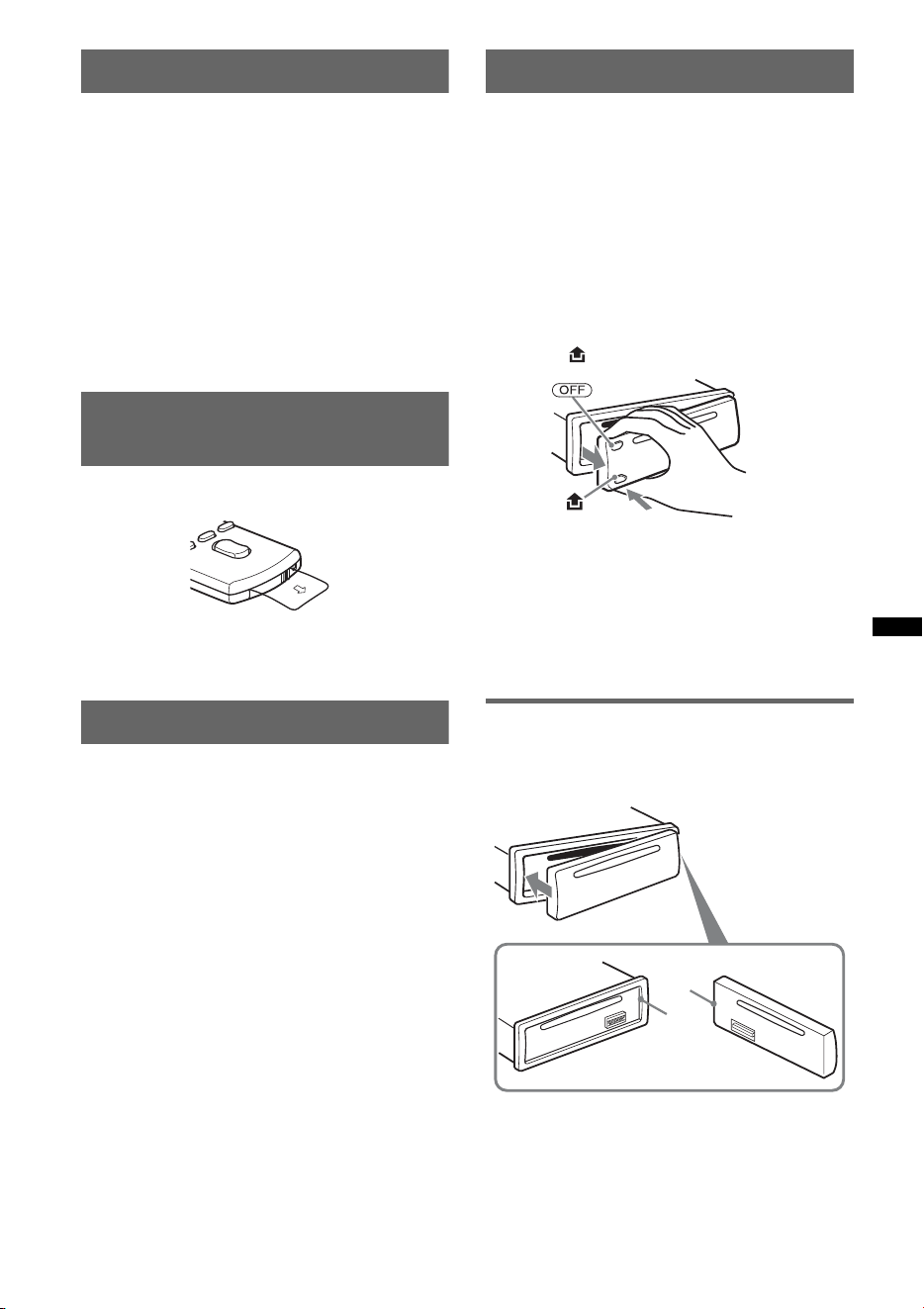
Detaching the front panel
You can detach the front panel of this unit to
prevent theft.
Caution alarm
If you turn the ignition switch to the OFF
position without detaching the front panel, the
caution alarm will sound for a few seconds.
The alarm will only sound if the built-in
amplifier is used.
1 Press (OFF).
The unit is turned off.
2 Press , then pull it off towards you.
Notes
• Do not drop or put excessive pressure on the front
panel and display window.
• Do not subject the front panel to heat/high
temperature or moisture. Avoid leaving it in a parked
car or on a dashboard/rear tray.
• Do not detach the front panel during playback of the
USB device, otherwise USB data may be damaged.
Attaching the front panel
Engage part A of the front panel with part B of
the unit, as illustrated, and push the left side into
position until it clicks.
Note
Do not put anything on the inner surface of the front
panel.
B
A
8
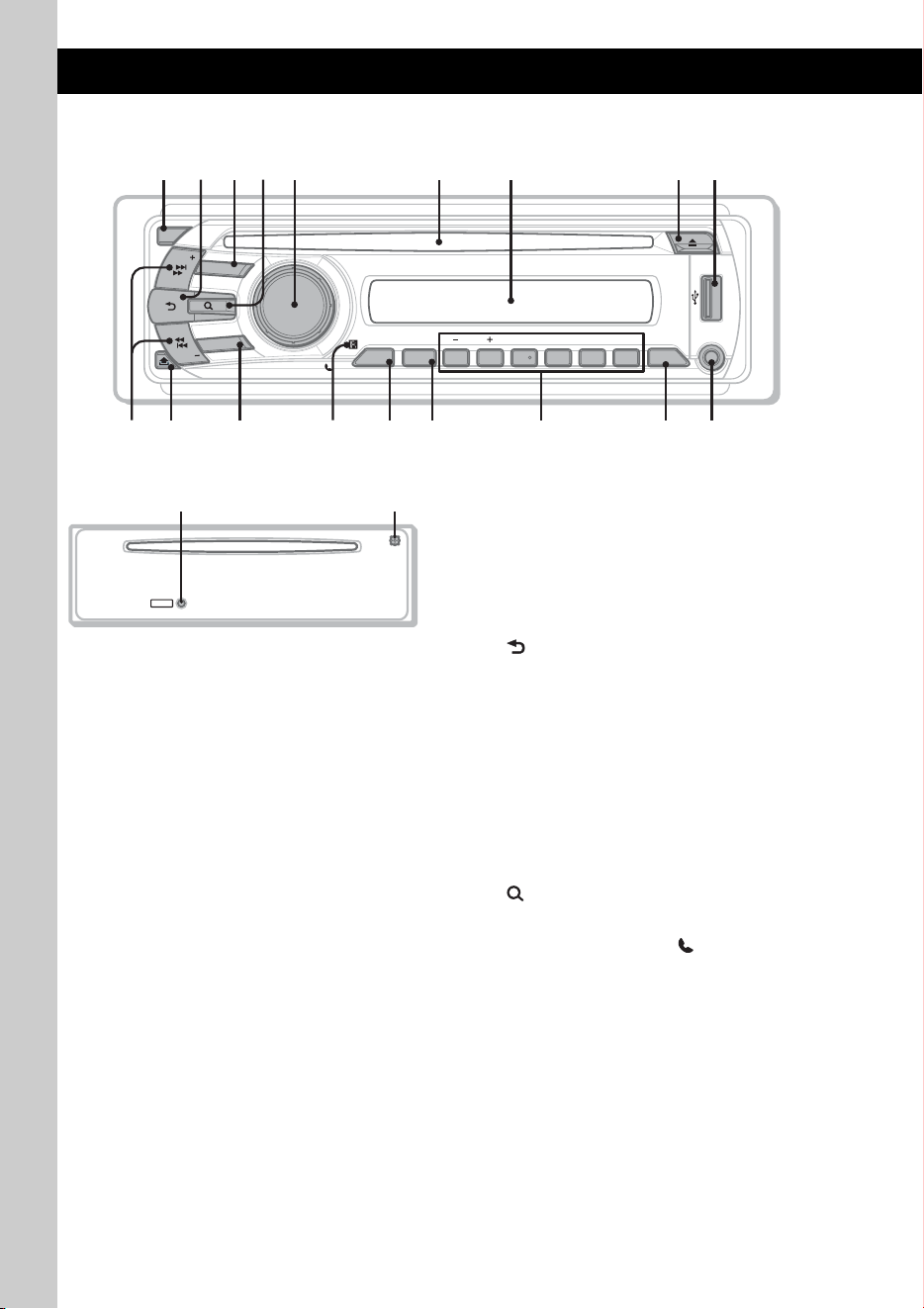
Location of controls and basic operations
Main unit
Front panel removed This section contains instructions on the location
of controls and basic operations. For details, see
the respective pages.
The corresponding buttons on the card remote
commander control the same functions as those
on the unit.
A OFF button
To power off; stop the source.
B (BACK)/MODE button page 11, 12,
14, 15, 16
Press to: Return to the previous display/
select the radio band (FM/AM)*
1
/select the
play mode of iPod.
Press and hold to: Enter/cancel the passenger
control.
C SOURCE button
To power on; change the source (Radio/CD/
USB/AUX/Bluetooth audio/Bluetooth
phone)*
1
.
D (BROWSE) button page 11
To enter the Quick-BrowZer mode.
E Control dial/select / (handsfree)
button
To adjust volume/select search category
(rotate); select setup items (press and rotate);
receive/end a call (press).
F Disc slot
Insert the disc (label side up), playback
starts.
G Display window
H Z (eject) button
To eject the disc.
I USB terminal page 13
To connect to the USB device.
ALBMARTISTRACK SHUF
+
DM
LOUDDISCREGTPTAAFZAP
AUX
BTMZAP
PAUSE
REP SHUF SCRL
OFF
1 2 3 4 5 6
ALBM
SOURCE
BT
BLUETOOTH
SEEK
SEEK
PUSH ENTER
/
SELECT
/
DSPL
MICCAT
MODE
1
q
a
q
;
9
2
q
s
q
j
q
k
q
g
4 65 7
8
3
q
h
q
f
q
d
RESET
w;ql

9
J SEEK +/– buttons
CD/USB:
To skip tracks (press); skip tracks
continuously (press, then press again within
about 1 second and hold); reverse/fast-
forward a track (press and hold).
Radio:
To tune in stations automatically (press); find
a station manually (press and hold).
Bluetooth audio device*
2
:
To skip tracks (press).
K (front panel release) button page 7
L BT (BLUETOOTH) button page 16
For Bluetooth signal on/off, pairing.
M Receptor for the card remote
commander
N ZAP button page 12
To enter ZAPPIN™ mode.
O BTM/CAT*
3
button page 12
To start the BTM function (press and hold).
P Number buttons
CD/USB:
(1)/(2): ALBM –/+ (during MP3/WMA/
AAC playback)
To skip albums (press); skip albums
continuously (press and hold).
(3): REP page 13, 14, 15
(4): SHUF page 13, 14, 15
(6): PAUSE
To pause playback. To cancel, press
again.
Radio:
To receive stored stations (press); store
stations (press and hold).
Bluetooth audio device*
2
:
(6): PAUSE
To pause playback. To cancel, press
again.
Bluetooth phone:
(5): MIC page 18
Q DSPL (display)/SCRL (scroll) button
page 13, 14, 15, 16
To change display items (press); scroll the
display item (press and hold).
R AUX input jack page 21
To connect a portable audio device.
S RESET button page 6
T Microphone page 18
Note
Do not cover the microphone, the handsfree
function may not work properly.
*1 In the case of a CD changer, HD Radio tuner or
SAT tuner being connected; when (SOURCE) is
pressed, the connected device (“HD,” “XM” or “SR”)
will appear in the display, depending on which
device is connected. Furthermore, if (MODE) is
pressed, you can switch the changer, HD Radio
tuner band or SAT tuner band.
*2 When a Bluetooth audio device (supports AVRCP
of Bluetooth technology) is connected. Depending
on the device, certain operations may not be
available.
*3 When the SAT tuner is connected.
Notes
• When ejecting/inserting a disc, keep any USB
devices disconnected to avoid damage to the disc.
• If the unit is turned off and the display disappears, it
cannot be operated with the card remote
commander unless (SOURCE) on the unit is
pressed, or a disc is inserted to activate the unit first.

10
Card remote commander
RM-X304
Some of the following buttons on the card remote
commander have different functions, or are
different from the unit. Remove the insulation
film before use (page 7).
A OFF button
To power off; stop the source.
B SOURCE button
To power on; change the source (Radio/CD/
USB/AUX/Bluetooth audio/Bluetooth
phone).
C < (.)/, (>) buttons
To control radio/CD/USB/Bluetooth audio,
the same as (SEEK) –/+ on the unit.
Setup, sound setting, etc., can be operated by
< ,.
D DSPL (display) button
To change display items.
E VOL (volume) +/– button
To adjust volume.
F ATT (attenuate) button
To attenuate the sound. To cancel, press
again.
G MODE button
Press to: Select the radio band (FM/AM)/
select the play mode of iPod.
Press and hold to: Enter/cancel the passenger
control.
H SEL (select)/ (handsfree) button
The same as the select button on the unit.
I M (+)/m (–) buttons
To control CD/USB, the same as (1)/(2)
(ALBM –/+) on the unit.
Setup, sound setting, etc., can be operated by
M m.
J SCRL (scroll) button
To scroll the display item.
K Number buttons
To receive stored stations (press); store
stations (press and hold).
OFF
DSPL
SCRL
SEL
SOURCE
MODE
132
465
ATT
VOL
+
–
+
–
2
8
7
1
0
3
6
5
4
qa
9
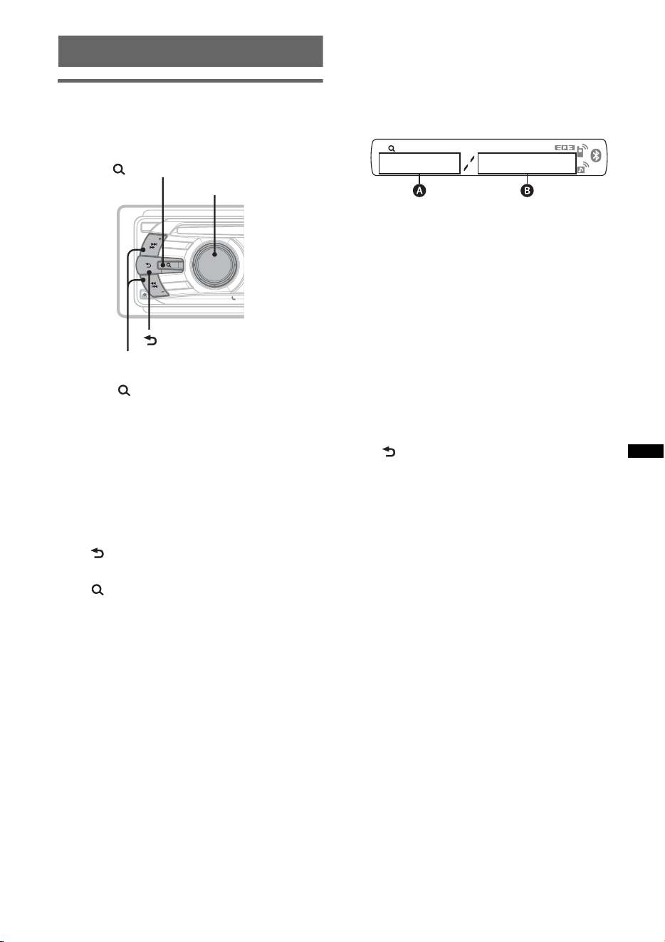
11
Searching for a track
Searching a track by name
— Quick-BrowZer
You can search for a track in a CD or USB device
easily by category.
1 Press (BROWSE).
The unit enters the Quick-BrowZer mode,
and the list of search categories appears.
2 Rotate the control dial to select the
desired search category, then press it
to confirm.
3 Repeat step 2 until the desired track is
selected.
Playback starts.
To return to the previous display
Press (BACK).
To exit the Quick-BrowZer mode
Press (BROWSE).
Note
When entering the Quick-BrowZer mode, the repeat/
shuffle setting is canceled.
Searching by skip items
— Jump mode
When many items are in a category, you can
search the desired item quickly.
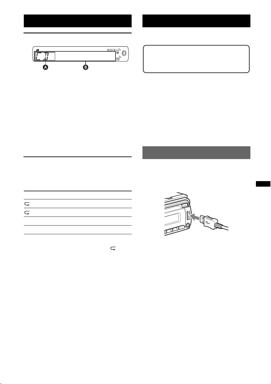
1 Press (SEEK) + in Quick-BrowZer mode.
The following display appears.
A Current item number
B Total item number in the current layer
Then the item name will appear.
2 Rotate the control dial to select the desired
item, or one near the desired item.
It skips in steps of 10% of the total item
number.
3 Press the select button.
The display returns to the Quick-BrowZer
mode and the selected item appears.
4 Rotate the control dial to select the desired
item and press it.
Playback starts if the selected item is a track.
To cancel Jump mode
Press (BACK) or (SEEK) –.
OFF
S
O
U
R
C
E
SEEK
S
E
E
K
B
T
BLUETOOTH
PUSH ENTER
/
SELECT
/
MODE
(BROWSE)
Control dial/
select button
(BACK)
SEEK +/–
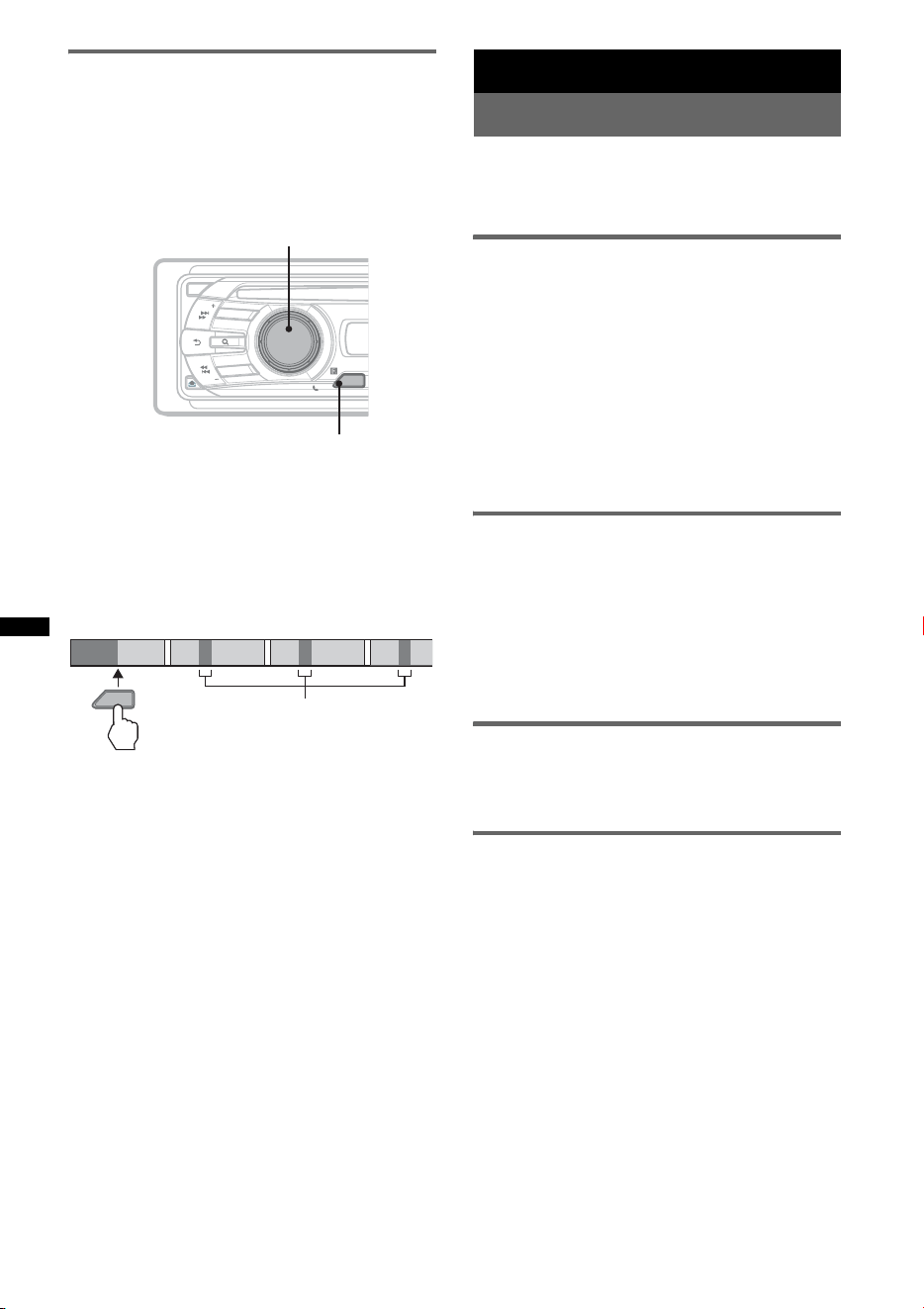
12
Searching a track by listening to
track passages — ZAPPIN™
While playing back short track passages in a CD
or USB device in sequence, you can search for a
track you want to listen to.
ZAPPIN mode is suitable for searching for a
track in shuffle or shuffle repeat mode.
1 Press (ZAP) during playback.
After “ZAPPIN” appears in the display,
playback starts from a passage of the next
track.
The passage is played for the set time, then a
click sounds and the next passage starts.
2 Press the select button or (ZAP) when
a track you want to listen is played
back.
The track that you select returns to normal
play mode from the beginning.
To search a track by ZAPPIN mode again,
repeat steps 1 and 2.
Tips
• You can select the playback time from about 6
seconds/9 seconds/30 seconds (page 21).You
cannot select the passage of the track to playback.
• Press (SEEK) –/+ or (1)/(2) (ALBM –/+) in ZAPPIN
mode to skip a track or album.
Radio
Storing and receiving stations
Caution
When tuning in stations while driving, use Best
Tuning Memory (BTM) to prevent an accident.
Storing automatically — BTM
1 Press (SOURCE) repeatedly until
“TUNER” appears.
To change the band, press (MODE)
repeatedly. You can select from FM1, FM2,
FM3, AM1 or AM2.
2 Press and hold (BTM) until “BTM”
flashes.
The unit stores stations in order of frequency
on the number buttons.
A beep sounds when the setting is stored.
Storing manually
1 While receiving the station that you
want to store, press and hold a
number button ((1) to (6)) until
“MEM” appears.
Note
If you try to store another station on the same number
button, the previously stored station will be replaced.
Receiving the stored stations
1 Select the band, then press a number
button ((1) to (6)).
Tuning automatically
1 Select the band, then press (SEEK) +/–
to search for the station.
Scanning stops when the unit receives a
station. Repeat this procedure until the
desired station is received.
Tip
If you know the frequency of the station you want to
listen to, press and hold ( SEEK) +/– to locate the
approximate frequency, then press ( SEEK) +/–
repeatedly to fine adjust to the desired frequency
(manual tuning).
ZAP
OFF
S
O
U
R
C
E
SEEK
S
E
E
K
B
T
BLUETOOTH
PUSH ENTER
/
SELECT
/
MODEMODE
ZAP
Select button
ZAP
1
1
2
2
3
3
4
4
The part of each track to
playback in ZAPPIN mode.
Track
13
CD
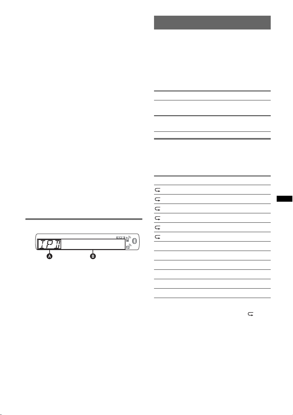
Display items
A Source
B Track name*
1
, Disc/artist name*
1
, Artist
name*
1
, Album number*
2
, Album name*
1
,
Track number/Elapsed playing time, Clock
*1 The information of a CD TEXT, MP3/WMA/AAC is
displayed.
*2 Album number is displayed only when the album is
changed.
To change display items B, press (DSPL).
Tip
Displayed items will differ depending on the disc type,
recording format and settings.
Repeat and shuffle play
1 During playback, press (3) (REP) or
(4) (SHUF) repeatedly until the
desired setting appears.
* When an MP3/WMA/AAC is played.
To return to normal play mode, select “ OFF”
or “SHUF OFF.”
USB devices
For details on the compatibility of your USB
device, visit the support site.
• MSC (Mass Storage Class) and MTP (Media
Transfer Protocol) type USB devices compliant
with the USB standard can be used.
• Corresponding codec is MP3 (.mp3), WMA
(.wma) and AAC (.m4a).
• Backup of data in a USB device is
recommended.
Note
Connect the USB device after starting the engine.
Depending on the USB device, malfunction or damage
may occur if it is connected before starting the engine.
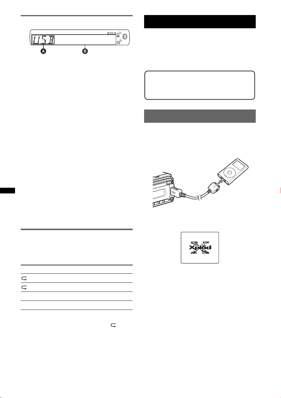
Playing back a USB device
1 Connect the USB device to the USB
terminal.
When using a cable, use the one supplied with
the USB device to connect.
Playback starts.
If a USB device is already connected, to start
playback, press (SOURCE) repeatedly until
“USB” appears.
Press (OFF) to stop playback.
Removing the USB device
1 Stop the USB device playback.
2 Remove the USB device.
If you remove your USB device during
playback, data in the USB device may be
damaged.
Notes
• Do not use USB devices so large or heavy that they
may fall down due to vibration, or cause a loose
connection.
• Do not detach the front panel during playback of the
USB device, otherwise USB data may be damaged.
• This unit cannot recognize USB devices via a USB
hub.
Select To play
TRACK track repeatedly.
ALBUM* album repeatedly.
SHUF ALBUM* album in random order.
SHUF DISC disc in random order.
Support site
http://esupport.sony.com
http://www.xplodsony.com/
14
Display items
A Source
B Track name, Artist name, Album number*,
Album name, Track number/Elapsed playing
time, Clock
* Album number is displayed only when the album is
changed.
To change display items B, press (DSPL).
Notes
• Displayed items will differ, depending on the USB
device, recorded format and settings. For details,
visit the support site.
• The maximum number of displayable data is as
follows.
– folders (albums): 128
– files (tracks) per folder: 500
• Do not leave a USB device in a parked car, as
malfunction may result.
• It may take time for playback to begin, depending on
the amount of recorded data.
• DRM (Digital Rights Management) files may not be
played.
• During playback or fast-forward/reverse of a VBR
(Variable Bit Rate) MP3/WMA/AAC file, elapsed
playing time may not display accurately.
• Playback of the following MP3/WMA/AAC files is not
supported.
– lossless compression
– copyright-protected
Repeat and shuffle play
1 During playback, press (3) (REP) or
(4) (SHUF) repeatedly until the
desired setting appears.
After 3 seconds, the setting is complete.
To return to normal play mode, select “ OFF”
or “SHUF OFF.”
iPod
For details on the compatibility of your iPod, see
“About iPod” on page 24 or visit the support site.
In these Operating Instructions, “iPod” is used as
a general reference for the iPod functions on the
iPod and iPhone, unless otherwise specified by
the text or illustrations.
Playing back iPod
Before connecting the iPod, turn down the
volume of the unit.
1 Connect the iPod to the USB terminal
via the dock connector to USB cable.
The iPod will turn on automatically, and the
display will appear on the iPod screen as
below.*
Tip
We recommend the RC-100IP USB cable (not
supplied) to connect the dock connector.
The tracks on the iPod start playing
automatically from the point last played.
If an iPod is already connected, to start
playback press (SOURCE) repeatedly until
“USB” appears. (“IPD” appears in the display
when iPod is recognized.)
* If the iPod was played back in the passenger control
last time, this will not appear.
2 Press (MODE) to select the play mode.
The mode changes as follows:
RESUMING t ALBUM t TRACK t
PODCAST* t GENRE t PLAYLIST
t ARTIST
* May not appear depending on iPod setting.
Select To play
TRACK track repeatedly.
ALBUM album repeatedly.
SHUF ALBUM album in random order.
SHUF DEVICE device in random order.
Support site
http://esupport.sony.com
http://www.xplodsony.com/
>
.
M
E
N
U
15
3 Adjust the volume.
Press (OFF) to stop playback.
Removing the iPod
1 Stop the iPod playback.
2 Remove the iPod.
Caution for iPhone
When you connect an iPhone via USB, telephone
volume is controlled by iPhone itself. In order to avoid
sudden loud sound after a call, do not increase the
volume on the unit during a telephone call.
Notes
• Do not detach the front panel during playback of the
iPod, otherwise data may be damaged.
• This unit cannot recognize iPod via a USB hub.
Tips
• When the ignition key is turned to the ACC position,
and the unit is on, the iPod will be recharged.
• If the iPod is disconnected during playback, “NO
DEV” appears in the display of the unit.
Resume mode
When the iPod is connected to the dock
connector, the mode of this unit changes to
resume mode and playback starts in the mode set
by the iPod.
In resume mode, the following buttons do not
function.
– (3) (REP)
– (4) (SHUF)
Display items
A Source (iPod) indication
B Track name, Artist name, Album name, Track
number/Elapsed playing time, Clock
To change display items B, press (DSPL).
Tip
When album/podcast/genre/artist/playlist is changed,
its item number appears momentarily.
Note
Some letters stored in iPod may not be displayed
correctly.
Setting the play mode
1 During playback, press (MODE).
The mode changes as follows:
ALBUM t TRACK t PODCAST* t
GENRE t PLAYLIST t ARTIST
* May not appear depending on iPod setting.
Skipping albums, podcasts, genres,
playlists and artists
Repeat and shuffle play
1 During playback, press (3) (REP) or
(4) (SHUF) repeatedly until the
desired setting appears.
After 3 seconds, the setting is complete.
To return to normal play mode, select “ OFF”
or “SHUF OFF.”
To Press
Skip (1)/(2) (ALBM –/+)
[press once for each]
Skip
continuously
(1)/(2) (ALBM –/+)
[hold to desired point]
Select To play
TRACK track repeatedly.
ALBUM album repeatedly.
PODCAST podcast repeatedly.
ARTIST artist repeatedly.
PLAYLIST playlist repeatedly.
GENRE genre repeatedly.
SHUF ALBUM album in random order.
SHUF PODCAST podcast in random order.
SHUF ARTIST artist in random order.
SHUF PLAYLIST playlist in random order.
SHUF GENRE genre in random order.
SHUF DEVICE device in random order.
16
Operating an iPod directly
— Passenger control
You can operate an iPod connected to the dock
connector directly.
1 During playback, press and hold
(MODE).
“MODE IPOD” appears and you will be able
to operate the iPod directly.
To change the display items
Press (DSPL).
The display items change as follows:
Track name t Artist name t Album name t
MODE IPOD t Clock
To exit the passenger control
Press and hold (MODE).
Then “MODE AUDIO” will appear and the play
mode will change to “RESUMING.”
Notes
• The volume can be adjusted only by the unit.
• If this mode is canceled, the repeat setting will be
turned off.
Bluetooth (Handsfree calling
and Music streaming)
Bluetooth operations
To use the Bluetooth function, the following
procedure is necessary.
1 Pairing
When connecting Bluetooth devices for the
first time, mutual registration is required. This
is called “pairing.” This registration (pairing)
is required only for the first time, as this unit
and the other devices will recognize each
other automatically from the next time. You
can pair up to 8 devices. (Depending on the
device, you may need to input a passcode for
each connection.)
2 Connection
To use the device after pairing is made, start
the connection. Sometimes pairing allows to
connect automatically.
3 Handsfree calling/Music streaming
You can talk handsfree and listen to music
when the connection is made.
Pairing
First, register (“pair”) a Bluetooth device
(cellular phone, etc.) and this unit with each
other. You can pair up to 8 devices. Once pairing
is established, there is no need for pairing again.
1 Place the Bluetooth device within 1 m
(3 ft) of this unit.
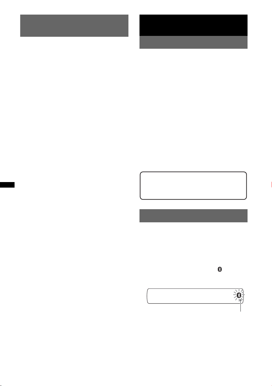
2 Press and hold (BT) until “ ” flashes
(about 5 seconds).
The unit enters pairing standby mode.
Support site
http://esupport.sony.com
http://www.xplodsony.com/
flashing
17
3 Set the Bluetooth device to search for
this unit.
A list of detected devices appears in the
display of the device to be connected. This
unit is displayed as “XPLOD” on the device
to be connected.
4 If Passcode* input is required on the
display of the device to be connected,
input “0000.”
This unit and the Bluetooth device memorize
each other’s information, and when pairing is
made, the unit is ready for connection to the
device.
“ ” flashes and then stays lit after pairing is
complete.
5 Set the Bluetooth device to connect to
this unit.
“ ” or “ ” appears when the connection is
made.
* Passcode may be called “passkey,” “PIN code,” “PIN
number” or “Password,” etc., depending on the
device.
Note
Pairing standby mode is not released until the
connection is made.
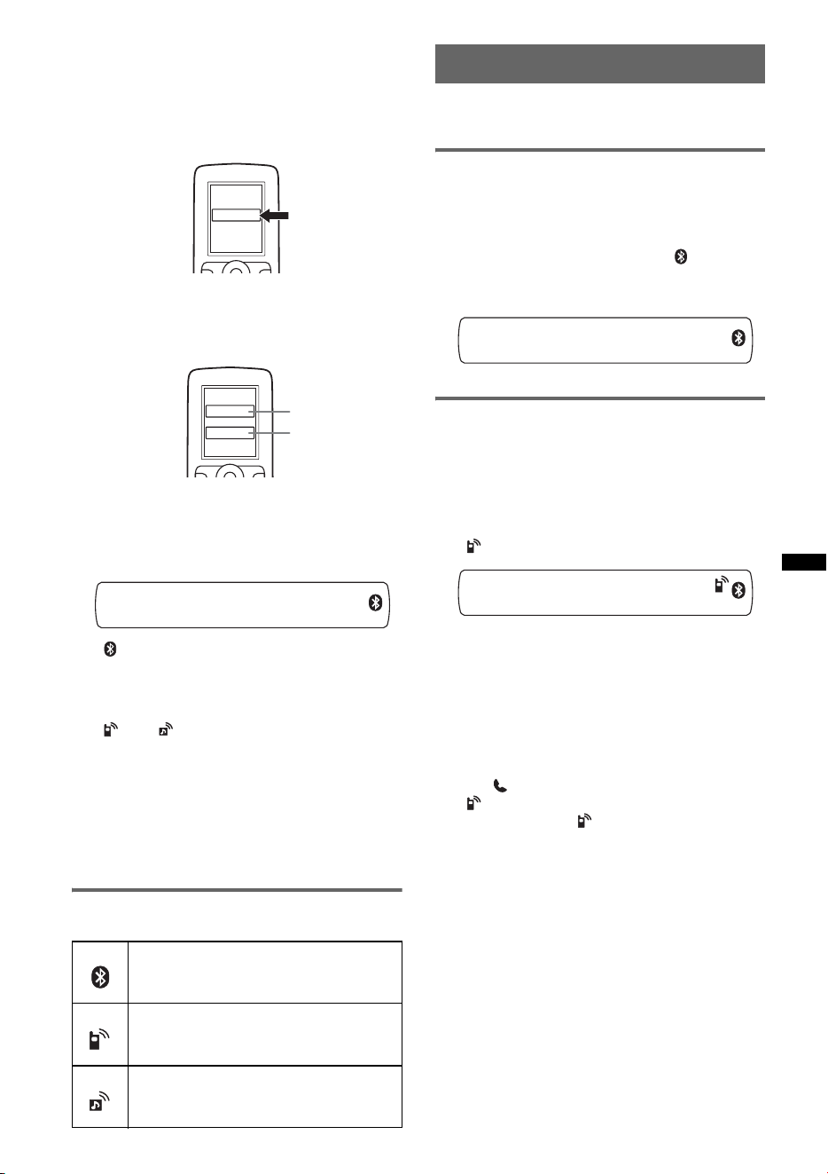
About Bluetooth icons
The following icons are used by this unit.
Connection
If pairing has already been achieved, start
operation from here.
To switch the Bluetooth signal
output of this unit to on
To use the Bluetooth function, switch the
Bluetooth signal output of this unit to on.
1 Press and hold (BT) until “ ” lights
(about 3 seconds).
Bluetooth signal is switched to on.
Connecting a cellular phone
1 Be sure that both this unit and the
cellular phone are switched to
Bluetooth signal on.
2 Connect to this unit using the cellular
phone.
“ ”appears when the connection is made.
Connecting the last-connected
cellular phone from this unit
1 Be sure that both this unit and the cellular
phone are switched to Bluetooth signal on.
2 Press (SOURCE) repeatedly until “BT
PHONE” appears.
3 Press (handsfree).
“ ” flashes while the connection is being
made. And then “ ” stays lit when the
connection is made.
Note
While streaming Bluetooth audio, you cannot connect
from this unit to the cellular phone. Connect from the
cellular phone to this unit instead. A connecting noise
may be heard over playback sound.
Tip
With Bluetooth signal on: when the ignition is switched
to on, this unit reconnects automatically to the last-
connected cellular phone. But automatic connection
also depends on the cellular phone’s specification. If
this unit does not reconnect automatically, connect
manually.
lit:
flashing:
off:
Bluetooth signal on
Pairing standby mode
Bluetooth signal off
lit:
flashing:
off:
Connection successful
Connecting
No connection
lit:
flashing:
off:
Connection successful
Connecting
No connection
XXXXXXX
DR-BT30Q
XPLOD
XXXX
Input passcode.
“0000”
18
Connecting an audio device
1 Be sure that both this unit and the
audio device are switched to
Bluetooth signal on.
2 Connect to this unit using the audio
device.
“ ” appears when the connection is made.
Connecting the last-connected audio
device from this unit
1 Be sure that both this unit and the audio device
are switched to Bluetooth signal on.
2 Press (SOURCE) repeatedly until “BT
AUDIO” appears.
3 Press (6).
“ ” flashes while the connection is being
made. And then “ ” stays lit when the
connection is made.
Handsfree calling
Check that the unit and cellular phone are
connected beforehand.
Receiving calls
When receiving a call, a ring tone is output from
your car speakers.
1 Press (handsfree) when a call is
received with a ring tone.
The phone call starts.
To end a call
Press (handsfree) again, or (OFF).
To reject an incoming call, press and hold
(handsfree) for 2 seconds.
Mic Gain adjustment
You can switch between two volume levels
(“LOW” or “HI”) to set a suitable level for the
other party during a call.
1 Press (5) during a call.
The item changes as follows:
MIC-LOW y MIC-HI
Note
The microphone of this unit is located on the rear of
the front panel (page 8). Do not cover the microphone
with tape, etc.
Making calls
In the case of making calls from this unit, redial
is used.
1 Press (SOURCE) repeatedly until “BT
PHONE” appears.
2 Press and hold (handsfree) for 3
seconds or more.
The phone call starts.
To end a call
Press (handsfree) again, or (OFF).
To call another phone, use your cellular phone,
and then transfer the call.
For call transfer details, check the following.
Call transfer
In order to activate/deactivate the appropriate
device (this unit/cellular phone), check the
following.
1 Press and hold (handsfree) or use
your cellular phone.
For details on cellular phone operation, refer to
your cellular phone manual.
Note
Depending on the cellular phone, handsfree
connection may be cut off when call transfer is
attempted.
Voice Dial Activation
You can activate voice dialing with a cellular
phone connected to this unit by saying the voice
tag stored on the cellular phone, then make a call.
1 Press (SOURCE) repeatedly until “BT
PHONE” appears.
2 Press (handsfree).
The cellular phone enters voice dialing mode.
3 Say the voice tag stored on the cellular
phone.
Your voice is recognized, and the call is
made.
19
Notes
• Check that unit and cellular phone are connected
beforehand.
• Store a voice tag on your cellular phone beforehand.
• If you activate voice dialing with a cellular phone
connected to this unit, this function may not always
work in some cases.
• Noises such as the engine running may interfere
with sound recognition. In order to improve
recognition, operate under conditions where noise is
minimized.
• Voice dialing may not work in some situations,
depending on the effectiveness of the cellular
phone’s recognition function. For details, see the
support site (page 27).
Tips
• Speak in the same way as you did when you stored
the voice tag.
• Store a voice tag while seated in the car, via this unit
with “BT PHONE” source selected.
Music streaming
Listening to music from an audio
device
You can listen to music of an audio device on this
unit if the audio device supports A2DP
(Advanced Audio Distribution Profile) of
Bluetooth technology.
1 Turn down the volume on this unit.
2 Press (SOURCE) repeatedly until “BT
AUDIO” appears.
3 Operate the audio device to start
playback.
4 Adjust the volume on this unit.
Adjusting the volume level
The volume level is adjustable for any difference
between the unit and the Bluetooth audio device.
1 Start playback of the Bluetooth audio device at
a moderate volume.
2 Set your usual listening volume on the unit.
3 Press the select button repeatedly until “BTA”
appears, and rotate the volume control dial to
adjust the input level (–8 dB to +18 dB).
Operating an audio device with this
unit
You can perform the following operations on this
unit if the audio device supports AVRCP (Audio
Video Remote Control Profile) of Bluetooth
technology. (The operation differs depending on
the audio device.)
* Depending on the device, it may be necessary to
press twice.
Operations other than the above should be
performed on the audio device.
Notes
• During audio device playback, information such as
track number/time, playback status, etc., of a
connected audio device is not displayed on this unit.
• Even if the source is changed on this unit, playback
of the audio device does not stop.
Tip
You can connect a cellular phone that supports A2DP
(Advanced Audio Distribution Profile) as an audio
device and listen to music.
Deleting registration of all
paired devices
1 Press (OFF).
This unit is turned off.
2 If “ ” lights, press and hold
(BT) until “ ” turns off.
3 Press and hold the select button.
4 Press the select button repeatedly
until “BT INIT” appears.
5 Press (SEEK) +.
Initializing starts.
It takes 3 seconds to cancel all registration.
Do not turn off the power while “INITIAL” is
flashing.
To Press
Play (6) (PAUSE)* on this unit.
Pause (6) (PAUSE)* on this unit.
Skip tracks SEEK –/+ (
./>) [once for
each track]
20
Other functions
Changing the sound settings
Adjusting the sound
characteristics
1 Press the select button repeatedly
until the desired item appears.
2 Rotate the control dial to adjust the
selected item.
3 Press (BACK).
The setting is complete and the display
returns to normal play/reception mode.
The following items can be set (follow the page
reference for details):
Customizing the equalizer curve
— EQ3
“CUSTOM” of EQ3 allows you to make your
own equalizer settings.
1 Select a source, then press the select
button repeatedly to select “EQ3.”
2 Rotate the control dial to select
“CUSTOM.”
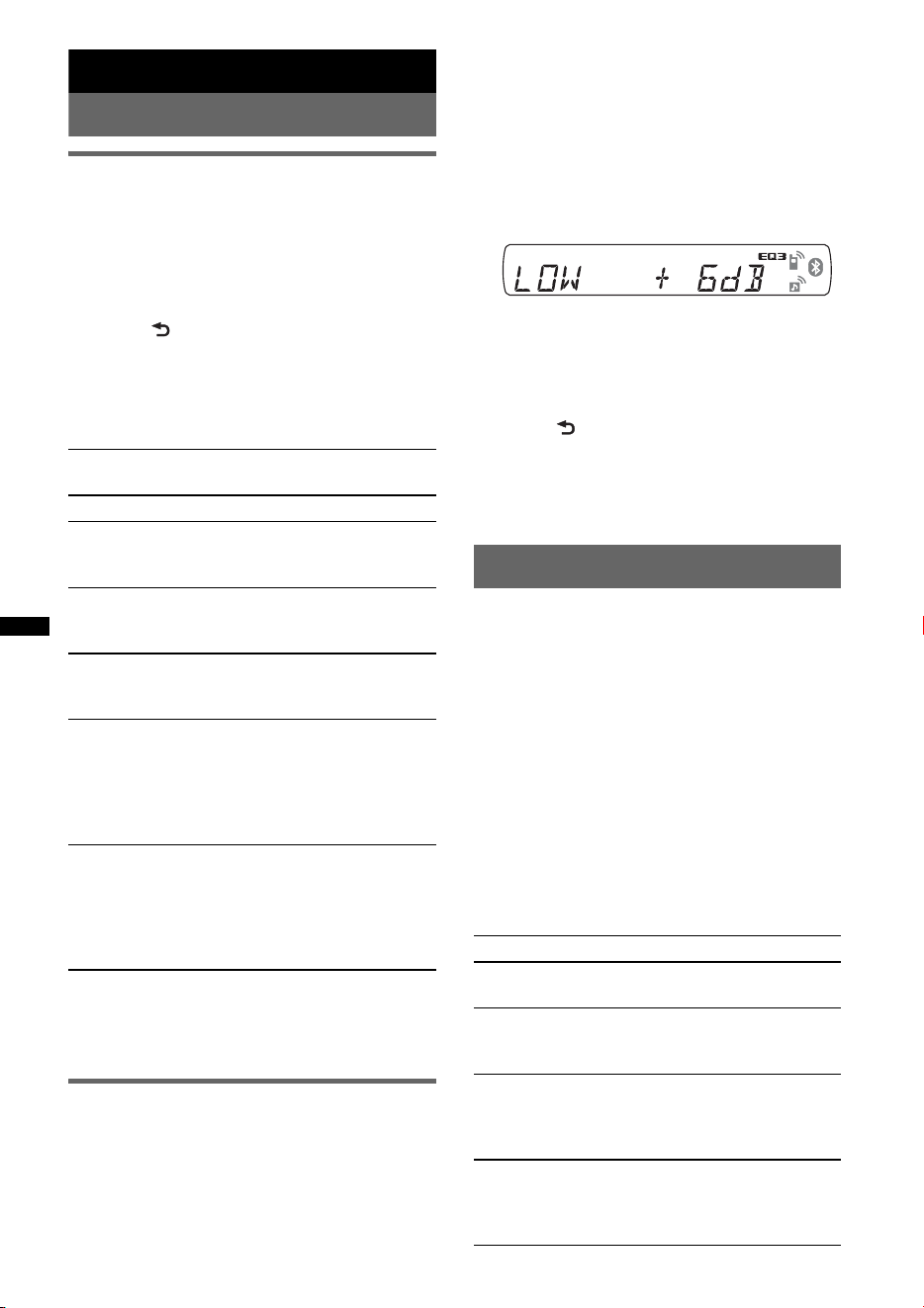
3 Press the select button repeatedly
until “LOW,” “MID” or “HI” appears.
4 Rotate the control dial to adjust the
selected item.
The volume level is adjustable in 1 dB steps,
from –10 dB to +10 dB.
Repeat steps 3 and 4 to adjust the equalizer
curve.
To restore the factory-set equalizer curve,
press and hold the select button before the
setting is complete.
5 Press (BACK).
The setting is complete and the display
returns to normal play/reception mode.
Tip
Other equalizer types are also adjustable.
Adjusting setup items — SET
1 Press and hold the select button.
The setup display appears.
2 Press the select button repeatedly
until the desired item appears.
3 Rotate the control dial to select the
setting (example “ON” or “OFF”).
4 Press and hold the select button.
The setup is complete and the display returns
to normal play/reception mode.
Note
Displayed items will differ, depending on the source
and setting.
The following items can be set (follow the page
reference for details):
EQ3
Selects an equalizer curve from 7 music types.
LOW*
1
, MID*
1
, HI*
1
(page 20)
BAL (Balance)
Adjusts the sound balance between the left and
right speakers.
FAD (Fader)
Adjusts the relative level between the front and
rear speakers.
SUB (Subwoofer volume)
Adjusts the subwoofer volume.
(“ATT” is the lowest setting.)
AUX*
2
(AUX level)
Adjusts the volume level for each connected
auxiliary equipment: “+18 dB” – “0 dB” – “–8
dB.”
This setting negates the need to adjust the
volume level between sources.
BTA*
3
(BT-Audio level)
Adjusts the volume level for each connected
Bluetooth audio device: “+18 dB” – “0 dB” –
“–8 dB.”
This setting negates the need to adjust the
volume level between sources (page 19).
*1 When EQ3 is activated.
*2 When AUX source is activated.
*3 When Bluetooth audio source is activated
(page 19).
CLOCK-ADJ (Clock Adjust) (page 7)
BEEP
Activates the beep sound: “ON,” “OFF.”
AUX-A*
1
(AUX Audio)
Activates the AUX source display: “ON,”
“OFF” (page 21).
A.OFF
Shuts off automatically after a desired time
when the unit is turned off: “NO,” “30S
(seconds),” “30M (minutes),” “60M (minutes).”
MIC*
1
– “EXT”: to automatically switch to the external
microphone when it is connected.
– “INT”: to select only the internal microphone.
21
Using optional equipment
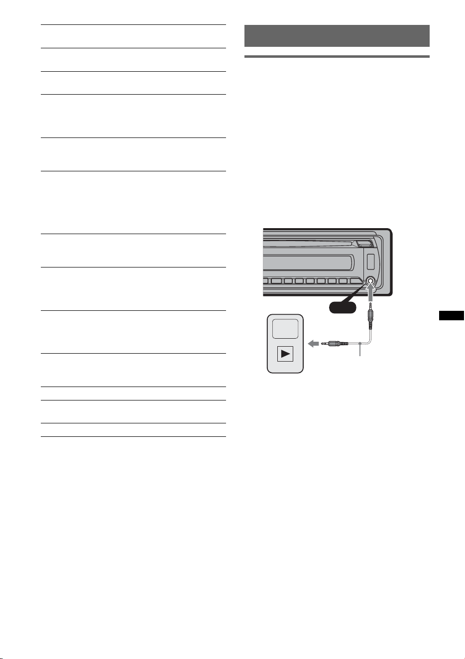
Auxiliary audio equipment
By connecting an optional portable audio device
to the AUX input jack (stereo mini jack) on the
unit and then simply selecting the source, you
can listen on your car speakers. The volume level
is adjustable for any difference between the unit
and the portable audio device. Follow the
procedure below:
Connecting the portable audio
device
1 Turn off the portable audio device.
2 Turn down the volume on the unit.
3 Connect to the unit.
* Be sure to use a straight type plug.
Adjust the volume level
Be sure to adjust the volume for each connected
audio device before playback.
1 Turn down the volume on the unit.
2 Press (SOURCE) repeatedly until “AUX”
appears.
“AUX FRONT IN” appears.
3 Start playback of the portable audio device at a
moderate volume.
4 Set your usual listening volume on the unit.
5 Adjust the input level (page 20).
DEMO
(Demonstration)
Activates the demonstration: “ON,” “OFF.”
DIM (Dimmer)
Changes the display brightness: “ON,” “OFF.”
A.SCRL*
2
(Auto Scroll)
Scrolls long items automatically: “ON,” “OFF.”
LOCAL (Local Seek Mode)
– “ON”: to only tune into stations with stronger
signals.
– “OFF”: to tune normal reception.
MONO*
3
(Monaural Mode)
Selects monaural reception mode to improve
poor FM reception: “ON,” “OFF.”
Z.TIME*
2
(Zappin Time)
Selects the playback time for the ZAPPIN
function.
– “Z.TIME-1 (about 6 seconds),” “Z.TIME-2
(about 9 seconds),” “Z.TIME-3 (about
30 seconds).”
LPF (Low Pass Filter)
Selects the subwoofer cut-off frequency: “OFF,”
“80Hz,” “100Hz,” “120Hz,” “140Hz,” “160Hz.”
LPF NORM/REV (Low Pass Filter Normal/
Reverse)
Selects the phase when the LPF is on: “NORM,”
“REV.”
HPF (High Pass Filter)
Selects the front/rear speaker cut-off frequency:
“OFF,” “80Hz,” “100Hz,” “120Hz,” “140Hz,”
“160Hz.”
LOUD (Loudness)
Reinforces bass and treble for clear sound at low
volume levels: “ON,” “OFF.”
BTM (page 12)
DM+*
2
To set the DM+ function: “ON,”“OFF.”
BT INIT*
1
(page 19)
*1 When the unit is turned off.
*2 When CD/USB source is activated.
*3 When FM is received.
AUX
AUX
Connecting cord*
(not supplied)
22
CD changer
Selecting the changer
1 Press (SOURCE) repeatedly until “CD”
appears.
2 Press (MODE) repeatedly until the desired
changer appears.
Playback starts.
Skipping albums and discs
1 During playback, press (1)/(2) (ALBM –/+).
Repeat and shuffle play
1 During playback, press (3) (REP) or (4)
(SHUF) repeatedly until the desired setting
appears.
To return to normal play mode, select “ OFF”
or “SHUF OFF.”
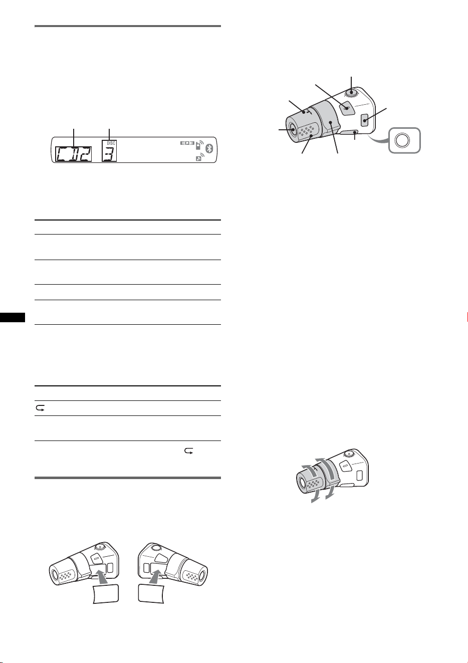
Rotary commander RM-X4S
Attaching the label
Attach the indication label depending on how
you mount the rotary commander.
Location of controls
The corresponding buttons on the rotary
commander control the same functions as those
on this unit.
The following controls on the rotary commander
require a different operation from the unit.
• ATT (attenuate) button
To attenuate the sound. To cancel, press again.
• SEL (select) button
The same as the select button on the unit.
• PRESET/DISC control
CD/USB: The same as (1)/(2) (ALBM –/+)
on the unit (push in and rotate).
Radio: To receive stored stations (push in and
rotate).
• VOL (volume) control
The same as the control dial on the unit (rotate).
• SEEK/AMS control
The same as (SEEK) +/– on the unit (rotate, or
rotate and hold).
• DSPL (display) button
To change display items.
• MODE button
Press to: Select the radio band (FM/AM)/ select
the play mode of iPod.
Press and hold to: Enter/cancel the passenger
control.
Changing the operative direction
The operative direction of the controls is factory-
set as shown below.
If you need to mount the rotary commander on
the right hand side of the steering column, you
can reverse the operative direction.
To skip Press (1)/(2) (ALBM –/+)
album and release (hold for a
moment).
album
continuously
within 2 seconds of first
releasing.
discs repeatedly.
discs
continuously
then, press again within 2
seconds and hold.
Select To play
DISC disc repeatedly.
SHUF
CHANGER
tracks in the changer in random
order.
Unit number Disc number
S
E
L
D
S
P
L
M
O
D
E
S
E
L
D
S
P
L
M
O
D
E
OFF
ATT
SEL
SOURCE
DSPL
MODE
OFF
VOL
SEEK/AMS
PRESET/
DISC
To increase
To decrease
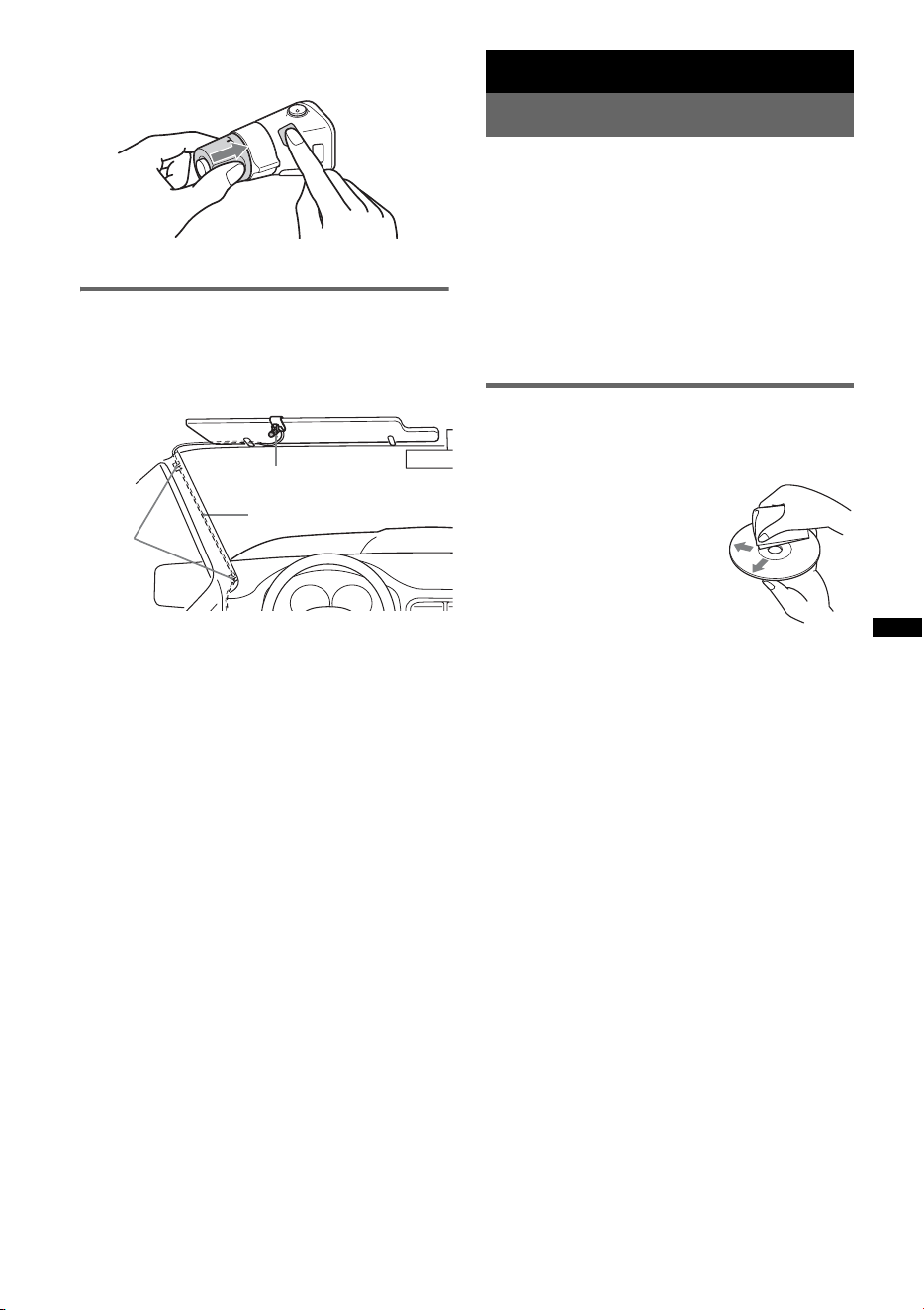
23
1 While pushing the VOL control, press and
hold ( SEL ).
External microphone XA-MC10
By connecting an optional external microphone
to the microphone input connector, you can
improve audio quality while talking thorough
this unit.
Tip
You can set the priority of the microphones (page 20).
Note
Connect XA-MC10 as the external microphone. You
may not be able to call or malfunction may occur if
another device is connected.
Additional Information
Precautions
• Cool off the unit beforehand if your car has been
parked in direct sunlight.
• Power antenna (aerial) extends automatically.
Moisture condensation
Should moisture condensation occur inside the unit,
remove the disc and wait for about an hour for it to
dry out; otherwise the unit will not operate properly.
To maintain high sound quality
Do not splash liquid onto the unit or discs.
Notes on discs
• Do not expose discs to direct sunlight or heat
sources such as hot air ducts, nor leave it in a car
parked in direct sunlight.
• Before playing, wipe the discs
with a cleaning cloth from the
center out. Do not use solvents
such as benzine, thinner,
commercially available
cleaners.
• This unit is designed to
playback discs that conform to
the Compact Disc (CD)
standard. DualDiscs and some of the music discs
encoded with copyright protection technologies do
not conform to the Compact Disc (CD) standard,
therefore, these discs may not be playable by this
unit.
• Discs that this unit CANNOT play
– Discs with labels, stickers, or sticky tape or
paper attached. Doing so may cause a
malfunction, or may ruin the disc.
– Discs with non-standard shapes (e.g., heart,
square, star). Attempting to do so may damage
the unit.
–8 cm (3
1
/4 in) discs
Notes on CD-R/CD-RW discs
• The maximum number of: (CD-R/CD-RW only)
– folders (albums): 150 (including root folder)
– files (tracks) and folders: 300 (may less than 300
if folder/file names contain many characters)
– displayable characters for a folder/file name: 32
(Joliet)/64 (Romeo)
• If the multi-session disc begins with a CD-DA
session, it is recognized as a CD-DA disc, and
other sessions are not played back.
• Discs that this unit CANNOT play
– CD-R/CD-RW of poor recording quality.
– CD-R/CD-RW recorded with an incompatible
recording device.
– CD-R/CD-RW which is finalized incorrectly.
External microphone
Connecting cord
Clamps
continue to next page t
24
– CD-R/CD-RW other than those recorded in
music CD format or MP3 format conforming to
ISO9660 Level 1/Level 2, Joliet/Romeo or
multi-session.
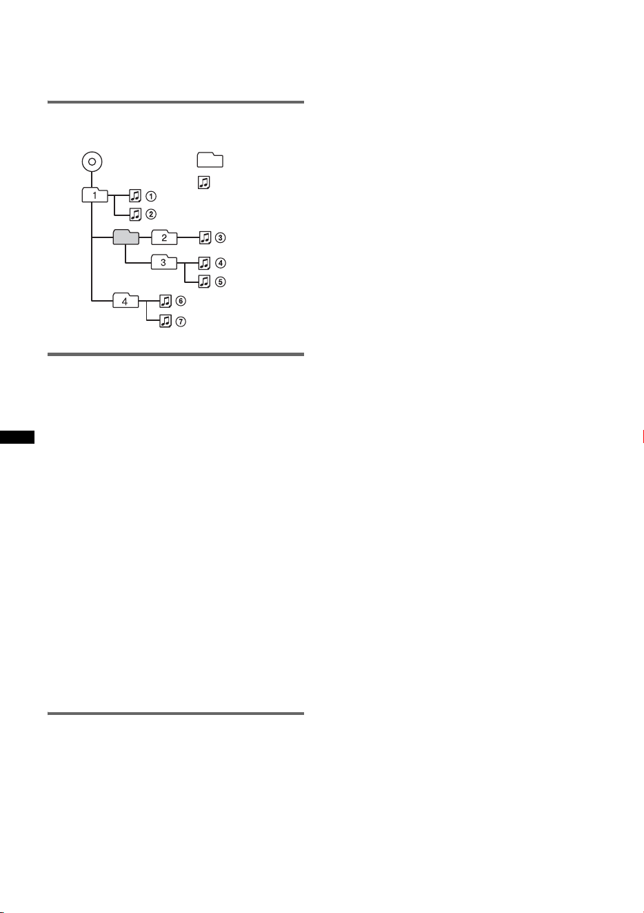
Playback order of MP3/WMA/AAC
files
About iPod
• You can connect to the following iPod models.
Update your iPod devices to the latest software
before use.
– iPod touch
– iPod classic
– iPod with video*
– iPod nano (3rd generation)
– iPod nano (2nd generation)
– iPod nano (1st generation)*
– iPhone and iPhone 3G
* Passenger control is not available for iPod nano (1st
generation) or iPod with video.
• “Made for iPod” means that an electronic
accessory has been designed to connect
specifically to iPod and has been certified by the
developer to meet Apple performance standards.
• “Works with iPhone” means that an electronic
accessory has been designed to connect
specifically to iPhone and has been certified by the
developer to meet Apple performance standards.
• Apple is not responsible for the operation of this
device or its compliance with safety and
regulatory standards.
About Bluetooth function
What is Bluetooth technology?
• Bluetooth wireless technology is a short-range
wireless technology that enables wireless data
communication between digital devices, such as a
cellular phone and a headset. Bluetooth wireless
technology operates within a range of about 10 m
(about 33 feet). Connecting two devices is
common, but some devices can be connected to
multiple devices at the same time.
• You do not need to use a cable for connection
since Bluetooth technology is a wireless
technology, neither is it necessary for the devices
to face one another, such is the case with infrared
technology. For example, you can use such a
device in a bag or pocket.
• Bluetooth technology is an international standard
supported by millions of companies all over the
world, and employed by various companies
worldwide.
On Bluetooth communication
• Bluetooth wireless technology operates within a
range of about 10 m.
Maximum communication range may vary
depending on obstacles (person, metal, wall, etc.)
or electromagnetic environment.
• The following conditions may affect the
sensitivity of Bluetooth communication.
– There is an obstacle such as a person, metal, or
wall between this unit and Bluetooth device.
– A device using 2.4 GHz frequency, such as a
wireless LAN device, cordless telephone, or
microwave oven, is in use near this unit.
• Because Bluetooth devices and wireless LAN
(IEEE802.11b/g) use the same frequency,
microwave interference may occur and result in
communication speed deterioration, noise, or
invalid connection if this unit is used near a
wireless LAN device. In such as case, perform the
following.
– Use this unit at least 10 m away from the
wireless LAN device.
– If this unit is used within 10 m of a wireless
LAN device, turn off the wireless LAN device.
– Install this unit and Bluetooth device as near to
each other as possible.
• Microwaves emitting from a Bluetooth device may
affect the operation of electronic medical devices.
Turn off this unit and other Bluetooth devices in
the following locations, as it may cause an
accident.
– where inflammable gas is present, in a hospital,
train, airplane, or petrol station
– near automatic doors or a fire alarm
• This unit supports security capabilities that
comply with the Bluetooth standard to provide a
secure connection when the Bluetooth wireless
technology is used, but security may not be
enough depending on the setting. Be careful when
communicating using Bluetooth wireless
technology.
• We do not take any responsibility for the leakage
of information during Bluetooth communication.
• Connection with all Bluetooth devices cannot be
guaranteed.
– A device featuring Bluetooth function is
required to conform to the Bluetooth standard
specified by Bluetooth SIG, and be
authenticated.
– Even if the connected device conforms to the
above mentioned Bluetooth standard, some
devices may not be connected or work correctly,
depending on the features or specifications of the
device.
Folder
(album)
MP3/WMA/
AAC file
(track)
MP3/WMA/AAC
25
– While talking on the phone hands free, noise
may occur, depending on the device or
communication environment.
• Depending on the device to be connected, it may
require some time to start communication.
Others
• Using the Bluetooth device may not function on
cellular phones, depending on radio wave
conditions and location where the equipment is
being used.
• If you experience discomfort after using the
Bluetooth device, stop using the Bluetooth device
immediately. Should any problem persist, consult
your nearest Sony dealer.
If you have any questions or problems concerning
your unit that are not covered in this manual, consult
your nearest Sony dealer.
Maintenance
Replacing the lithium battery of the
card remote commander
Under normal conditions, the battery will last
approximately 1 year. (The service life may be
shorter, depending on the conditions of use.)
When the battery becomes weak, the range of the
card remote commander becomes shorter. Replace
the battery with a new CR2025 lithium battery. Use
of any other battery may present a risk of fire or
explosion.
Notes on the lithium battery
• Keep the lithium battery out of the reach of children.
Should the battery be swallowed, immediately
consult a doctor.
• Wipe the battery with a dry cloth to assure a good
contact.
• Be sure to observe the correct polarity when
installing the battery.
• Do not hold the battery with metallic tweezers,
otherwise a short-circuit may occur.
Fuse replacement
When replacing the fuse, be
sure to use one matching the
amperage rating stated on the
original fuse. If the fuse blows,
check the power connection and
replace the fuse. If the fuse
blows again after replacement,
there may be an internal
malfunction. In such a case,
consult your nearest Sony
dealer.
Cleaning the connectors
The unit may not function properly if the connectors
between the unit and the front panel are not clean. In
order to prevent this, detach the front panel (page 7)
and clean the connectors with a cotton swab. Do not
apply too much force. Otherwise, the connectors
may be damaged.
Notes
• For safety, turn off the ignition before cleaning the
connectors, and remove the key from the ignition
switch.
• Never touch the connectors directly with your fingers
or with any metal device.
1
2
+ side up
c
WARNING
Battery may explode if mistreated.
Do not recharge, disassemble, or dispose of
in fire.
Fuse (10 A)
Main unit Back of the front
panel
26
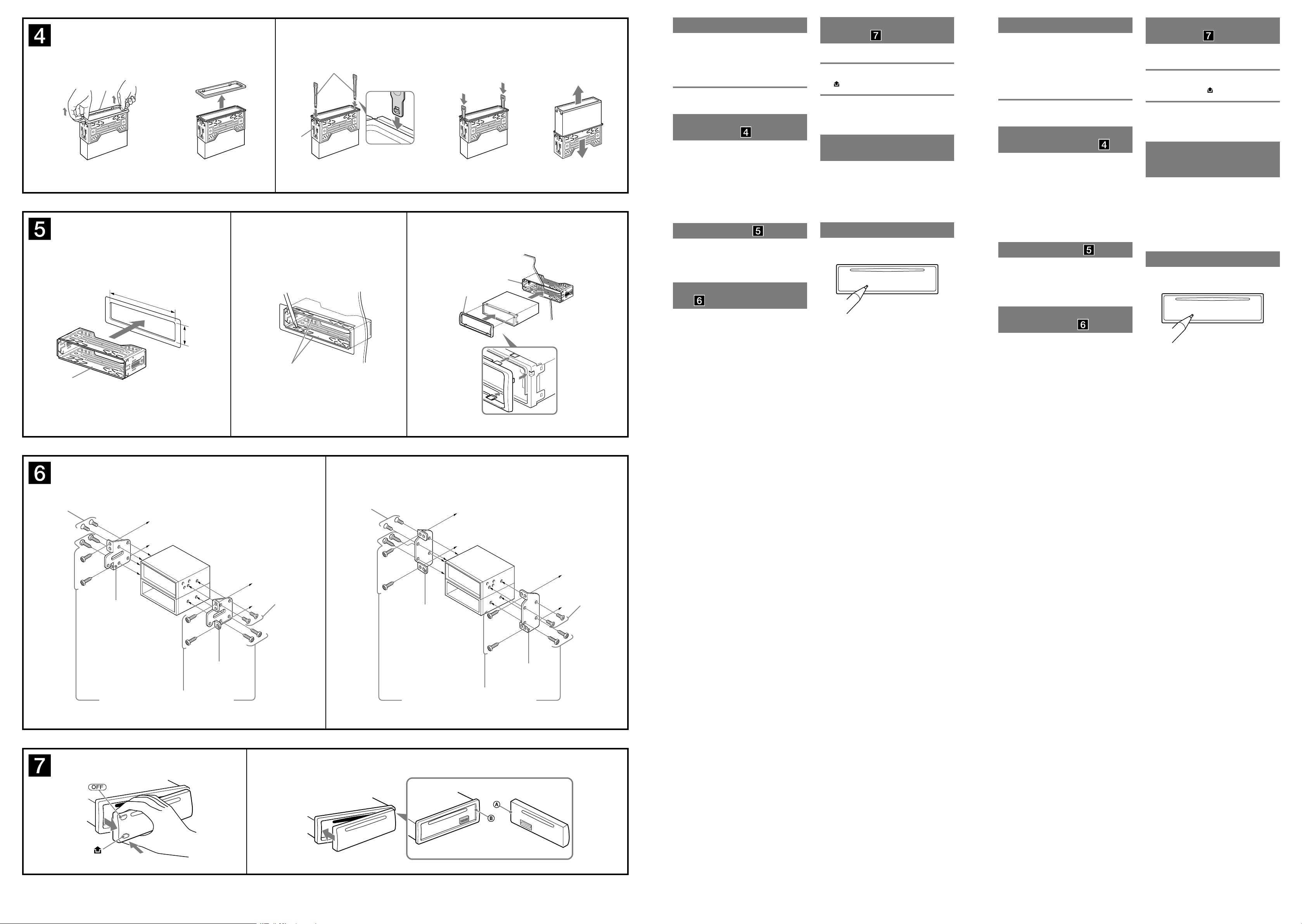
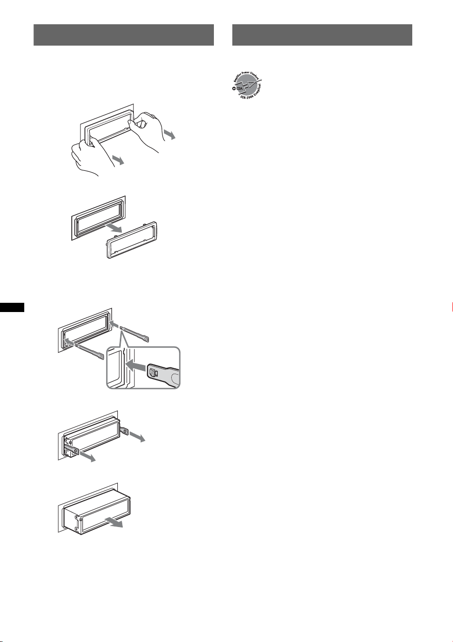
Removing the unit
1 Remove the protection collar.
1 Detach the front panel (page 7).
2 Pinch both edges of the protection collar,
then pull it out.
2 Remove the unit.
1 Insert both release keys simultaneously
until they click.
2 Pull the release keys to unseat the unit.
3 Slide the unit out of the mounting.
Specifications
AUDIO POWER SPECIFICATIONS
CD Player section
Signal-to-noise ratio: 120 dB
Frequency response: 10 – 20,000 Hz
Wow and flutter: Below measurable limit
Tuner section
FM
Tuning range: 87.5 – 107.9 MHz
Antenna (aerial) terminal:
External antenna (aerial) connector
Intermediate frequency: 150 kHz
Usable sensitivity: 10 dBf
Selectivity: 75 dB at 400 kHz
Signal-to-noise ratio: 70 dB (mono)
Separation: 40 dB at 1 kHz
Frequency response: 20 – 15,000 Hz
AM
Tuning range: 530 – 1,710 kHz
Antenna (aerial) terminal:
External antenna (aerial) connector
Intermediate frequency: 25 kHz
Sensitivity: 26 µV
USB Player section
Interface: USB (Full-speed)
Maximum current: 500mA
Wireless Communication
Communication System:
Bluetooth Standard version 2.0
Output:
Bluetooth Standard Power Class 2 (Max. +4 dBm)
Maximum communication range:
Line of sight approx. 10 m (33 ft)*
1
Frequency band:
2.4 GHz band (2.4000 – 2.4835 GHz)
Modulation method: FHSS
Compatible Bluetooth Profiles*
2
:
A2DP (Advanced Audio Distribution Profile)
AVRCP (Audio Video Remote Control Profile)
HFP (Handsfree Profile) 1.5
HSP (Headset Profile)
*1 The actual range will vary depending on factors
such as obstacles between devices, magnetic
fields around a microwave oven, static electricity,
reception sensitivity, antenna’s perfomance,
operating system, software application, etc.
*2 Bluetooth standard profiles indicate the purpose of
Bluetooth communication between devices.
x
Hook facing
inwards.
CEA2006 Standard
Power Output: 17 Watts RMS × 4 at
4 Ohms < 1% THD+N
SN Ratio: 82 dBA
(reference: 1 Watt into 4 Ohms)
27
Power amplifier section
Output: Speaker outputs (sure seal connectors)
Speaker impedance: 4 – 8 ohms
Maximum power output: 52 W × 4 (at 4 ohms)
General
Outputs:
Audio outputs terminal (front/rear)
Subwoofer output terminal (mono)
Power antenna (aerial) relay control terminal
Power amplifier control terminal
Inputs:
Remote controller input terminal
Antenna (aerial) input terminal
Telephone ATT control terminal
BUS control input terminal
BUS audio input terminal
AUX input jack (stereo mini jack)
USB signal input terminal
Tone controls:
Low: ±10 dB at 60 Hz (XPLOD)
Mid: ±10 dB at 1 kHz (XPLOD)
High: ±10 dB at 10 kHz (XPLOD)
Power requirements: 12 V DC car battery
(negative ground (earth))
Dimensions: Approx. 178 × 50 × 179 mm
(7
1
/8 × 2 × 7
1
/8 in) (w/h/d)
Mounting dimensions: Approx. 182 × 53 × 162 mm
(7
1
/4 × 2
1
/8 × 6
1
/2 in) (w/h/d)
Mass: Approx. 1.2 kg (2 lb 11 oz)
Supplied accessories:
Card remote commander: RM-X304
Parts for installation and connections (1 set)
Optional accessories/equipment:
Rotary commander: RM-X4S
BUS cable (supplied with an RCA pin cord):
RC-61 (1 m), RC-62 (2 m)
CD changer (10 discs): CDX-757MX
CD changer (6 discs): CDX-T69
Source selector: XA-C40
AUX-IN selector: XA-300
USB connection cable for iPod: RC-100IP
HD Radio
TM
tuner: XT-100HD
External microphone: XA-MC10
Your dealer may not handle some of the above listed
accessories. Please ask the dealer for detailed
information.
Design and specifications are subject to change
without notice.
Troubleshooting
The following checklist will help you remedy
problems you may encounter with your unit.
Before going through the checklist below, check the
connection and operating procedures.
If the problem is not solved, visit the following
support site.
• Halogenated flame retardants are not used in the
certain printed wiring boards.
• Halogenated flame retardants are not used in
cabinets.
• Packaging cushions are made from paper.
General
No power is being supplied to the unit.
• Check the connection or fuse.
• If the unit is turned off and the display disappears, it
cannot be operated with the remote commander.
t Turn on the unit.
The power antenna (aerial) does not extend.
The power antenna (aerial) does not have a relay box.
No sound.
• The ATT function is activated, or the Telephone ATT
function (when the interface cable of a car telephone
is connected to the ATT lead) is activated.
• The position of the fader control “FAD” is not set for
a 2-speaker system.
• The Bluetooth audio device is in pause.
t Cancel pause.
No beep sound.
• The beep sound is canceled (page 20).
• An optional power amplifier is connected and you are
not using the built-in amplifier.
The contents of the memory have been erased.
• The RESET button has been pressed.
t Store again into the memory.
• The power supply lead or battery has been
disconnected or it is not connected properly.
Stored stations and correct time are erased.
The fuse has blown.
Makes noise when the position of the ignition
is switched.
The leads are not matched correctly with the car’s
accessory power connector.
During playback or reception, demonstration
mode starts.
If no operation is performed for 5 minutes with
“DEMO-ON” set, demonstration mode starts.
t Set “DEMO-OFF” (page 21).
continue to next page t
Support site
http://esupport.sony.com
http://www.xplodsony.com/
28
The display disappears from/does not appear
in the display window.
• The dimmer is set “DIM-ON” (page 21).
• The display disappears if you press and hold (OFF).
tPress and hold (OF F) on the unit until the
display appears.
• The connectors are dirty (page 25).
The Auto Off function does not operate.
The unit is turned on. The Auto Off function activates
after turning off the unit.
t Turn off the unit.
CD playback
The disc cannot be loaded.
• Another disc is already loaded.
• The disc has been forcibly inserted upside down or in
the wrong way.
The disc does not playback.
• Defective or dirty disc.
• The CD-Rs/CD-RWs are not for audio use (page 23).
MP3/WMA/AAC files cannot be played back.
The disc is incompatible with the MP3/WMA/AAC
format and version. For details on playable discs and
formats, visit the support site.
MP3/WMA/AAC files take longer to play back
than others.
The following discs take a longer time to start
playback.
– a disc recorded with a complicated tree structure.
– a disc recorded in Multi Session.
– a disc to which data can be added.
The display items do not scroll.
• For discs with very many characters, those may not
scroll.
• “A.SCRL” is set to “OFF.”
tSet “A.SCRL-ON” (page 21).
tPress and hold (DS PL) (SCRL).
The sound skips.
• Installation is not correct.
tInstall the unit at an angle of less than 45° in a
sturdy part of the car.
• Defective or dirty disc.
The operation buttons do not function.
The disc will not eject.
Press the RESET button (page 6).
Radio reception
The stations cannot be received.
The sound is hampered by noises.
The connection is not correct.
t Connect a power antenna (aerial) control lead
(blue) or accessory power supply lead (red) to the
power supply lead of a car’s antenna (aerial)
booster (only when your car has built-in FM/AM
antenna (aerial) in the rear/side glass).
t Check the connection of the car antenna (aerial).
t If the auto antenna (aerial) will not go up, check the
connection of the power antenna (aerial) control
lead.
Preset tuning is not possible.
• Store the correct frequency in the memory.
• The broadcast signal is too weak.
Automatic tuning is not possible.
• Setting of the local seek mode is not correct.
t Tuning stops too frequently:
Set “LOCAL-ON” (page 21).
t Tuning does not stop at a station:
Set “LOCAL-OFF” (page 21).
• The broadcast signal is too weak.
t Perform manual tuning.
During FM reception, the “ST” indication
flashes.
• Tune in the frequency accurately.
• The broadcast signal is too weak.
t Set “MONO-ON” (page 21).
An FM program broadcast in stereo is heard in
monaural.
The unit is in monaural reception mode.
t Set “MONO-OFF” (page 21).
USB playback
You cannot play back items via a USB hub.
This unit cannot recognize USB devices via a USB
hub.
Cannot play back items.
A USB device does not work.
t Reconnect it.
The USB device takes longer to play back.
The USB device contains files with a complicated tree
structure.
A beep sounds.
During playback, the USB device has been
disconnected.
t Before disconnecting a USB device, make sure to
stop playback first for data protection.
The sound is intermittent.
The sound may be intermittent at a high-bit-rate of
more than 320 kbps.
Bluetooth function
The connecting device cannot detect this unit.
• Before the pairing is made, set this unit to pairing
standby mode.
• While connected to a Bluetooth device, this unit
cannot be detected from another device. Disconnect
the current connection and search for this unit from
another device.
• When the device pairing is made, set the Bluetooth
signal output to on (page 17).
Connection is not possible.
• Connect to this unit from a Bluetooth device or vice
versa. The connection is controlled from one side
(this unit or Bluetooth device), but not both.
• Check the pairing and connection procedures in the
manual of the other device, etc., and perform the
operation again.
The talker’s voice volume is low.
Adjust the volume level.
29
Error displays/Messages
A call partner says that the volume is too low
or high.
Adjust the volume accordingly using Mic Gain
adjustment (page 18).
Echo or noise occurs in phone call
conversations.
• Lower the volume.
• If the ambient noise other than the phone call sound
is loud, try reducing this noise.
E.g.: If a window is open and road noise, etc., is loud,
shut the window. If the air conditioner is loud, lower
the air conditioner.
The phone is not connected.
When the Bluetooth audio is played back, the phone is
not connected even if you press (handsfree).
tConnect from the phone.
The phone sound quality is poor.
Phone sound quality depends on reception conditions
of cellular phone.
tMove your car to a place where you can enhance
the cellular phone’s signal if the reception is poor.
The volume of the connected audio device is
low (high).
Volume level will differ depending on the audio
device.
tAdjust the volume of the connected audio device or
this unit.
The sound skips during playback of a
Bluetooth audio device.
• Reduce the distance between the unit and the
Bluetooth audio device.
• If the Bluetooth audio device is stored in a case
which interrupts the signal, remove the audio device
from the case while using.
• Several Bluetooth devices or other devices which
emit radio waves are used nearby.
t Turn off the other devices.
t Reduce the distance from the other devices.
• The playback sound stops momentarily when the
connection between this unit and the cellular phone is
being made. This is not a malfunction.
The connected Bluetooth audio device cannot
be controlled.
Check that the connected Bluetooth audio device
supports AVRCP.
Some functions do not work.
Check if the connecting device supports the functions
in question.
A call is answered unintentionally.
The connecting phone is set to answer a call
automatically.
No sound is output from the car speakers
during handsfree call.
If the sound is output from the cellular phone, set the
cellular phone to output the sound from the car
speakers.
“OFF BT” appears when initializing.
Press and hold (BT) until “ ” turns off. Then
initialize again (page 19).
The external microphone does not work.
The setting of the microphone is not correct.
t Set “MIC-EXT” (page 20).
CHECKING
The unit is confirming the connection of a USB device.
t Wait until confirming the connection is finished.
ERROR*
1
• The disc is dirty or inserted upside down.*
2
t Clean or insert the disc correctly.
• A blank disc has been inserted.
• The disc cannot play due to a problem.
t Insert another disc.
• USB device was not automatically recognized.
t Reconnect it again.
• Press Z to remove the disc.
FAILURE (Illuminates until any button is pressed.)
The connection of speakers/amplifiers is incorrect.
t See the installation guide manual of this model to
check the connection.
FAILURE (Illuminates for about 1 second.)
When the SAT tuner is connected, storing an SAT
radio channel into a preset failed.
t Be sure to receive the channel that you want to
store, then try it again.
HUB NO SUPRT
USB hub is not supported on this unit.
LOAD
The CD changer is loading the disc.
t Wait until loading is complete.
L. SEEK +/–
The local seek mode is on during automatic tuning.
NO DEV (No Device)
(SOURCE) is selected without a USB device
connected. A USB device or a USB cable has been
disconnected during playback.
t Be sure to connect a USB device and USB cable.
NO DISC
The disc is not inserted in the CD changer.
t Insert discs in the CD changer.
NO MAG
The disc magazine is not inserted in the CD changer.
t Insert the disc magazine in the CD changer.
NO MUSIC
The disc or USB device does not contain a music file.
t Insert a music CD in this unit or an MP3 playable
CD changer.
t Connect a USB device with a music file in it.
NO NAME
A disc/album/artist/track name is not written in the
track.
continue to next page t
30
If these solutions do not help improve the situation,
consult your nearest Sony dealer.
If you take the unit to be repaired because of CD
playback trouble, bring the disc that was used at the
time the problem began.
OFFSET
There may be an internal malfunction.
t Check the connection. If the error indication
remains on in the display, consult your nearest
Sony dealer.
OVERLOAD
USB device is overloaded.
t Disconnect the USB device, then change the source
by pressing (SOURCE).
t Indicates that the USB device is out of order, or an
unsupported device is connected.
READ
The unit is reading all track and album information on
the disc.
t Wait until reading is complete and playback starts
automatically. Depending on the disc structure, it
may take more than a minute.
RESET
The CD unit, CD changer or USB device cannot be
operated due to a problem.
t Press the RESET button (page 6).
USB NO SUPRT (USB Not Support)
The connected USB device is not supported.
t For details on the compatibility of your USB
device, visit the support site.
“” or “”
During reverse or fast-forward, you have reached the
beginning or the end of the disc and you cannot go any
further.
“”
The character cannot be displayed with the unit.
*1 If an error occurs during playback of a CD, the disc
number of the CD does not appear in the display.
*2 The disc number of the disc causing the error
appears in the display.

2
Nota sobre la pila de litio
No exponga la pila a fuentes de calor excesivo como
luz solar directa, fuego o similar.
La marca de la palabra Bluetooth y sus logotipos
son propiedad de Bluetooth SIG, Inc. y cualquier
uso de éstos por parte de Sony Corporation se
realiza bajo licencia. Las demás marcas y
nombres comerciales pertenecen a sus
respectivos propietarios.
ZAPPIN es una marca comercial de Sony
Corporation.
iPod es una marca comercial de Apple Inc.,
registrada en los Estados Unidos y en otros
países.
iPhone es una marca comercial de Apple Inc.
Asegúrese de instalar esta unidad en el tablero
del automóvil por razones de seguridad. Para
realizar la instalación y las conexiones,
consulte el manual de conexiones y de
instalación suministrado.
Windows Media y el logotipo
de Windows son marcas
comerciales o marcas
comerciales registradas de
Microsoft Corporation en Estados Unidos o en
otros países.
Tecnología de codificación de audio MPEG
Layer-3 y patentes bajo licencia de Fraunhofer IIS
y Thomson.
Este producto está protegido por los derechos de
propiedad intelectual de Microsoft Corporation.
Queda prohibido el uso o la distribución de esta
tecnología fuera de este producto si no se dispone
de una licencia de Microsoft o una división
autorizada de Microsoft.
Los proveedores de contenidos utilizan la
tecnología de gestión de derechos digitales para
Windows Media contenida en este dispositivo
(“WM-DRM”) para proteger la integridad de su
contenido (“Contenido seguro”) para que no se
realice un uso inapropiado de su propiedad
intelectual, incluyendo el copyright.
Este dispositivo utiliza software WM-DRM para
reproducir Contenido seguro (“Software WM-
DRM”). Si la seguridad del Software WM-DRM
de este dispositivo está en peligro, los propietarios
de los Contenido seguro (“Propietarios del
contenido seguro”) pueden solicitar que Microsoft
revoque el derecho del Software WM-DRM a
adquirir nuevas licencias para copiar, visualizar y/o
reproducir Contenido seguro. La revocación no
afecta a la capacidad del Software WM-DRM para
reproducir contenido no protegido. Se envía al
dispositivo una lista del Software WM-DRM
revocado cuando descarga una licencia para
Contenido seguro de Internet o de un PC. En
conjunción con esta licencia, Microsoft puede
descargar también listas de revocación en su
dispositivo de parte del programa de propietarios
de contenidos seguros.
El logotipo “HD Radio Ready” indica que este
p
roducto controlará un sintonizador HD
Radio
TM
de Sony (se vende por separado).
Para obtener información acerca del
funcionamiento del sintonizador HD Radio
TM
,
consulte el manual de instrucciones del
sintonizador HD Radio
TM
.
HD Radio
TM
y el logo HD Radio Ready son
marcas propietarias de iBiquity Digital Corp.
El logotipo “SAT Radio
Ready” indica que este
producto controla un módulo
de sintonizador de radio por
satélite (se vende por separado). Si desea
obtener más detalles sobre el módulo de
sintonizador de radio por satélite, póngase en
contacto con el distribuidor Sony autorizado
más cercano.
“SAT Radio”, “SAT Radio Ready”, los
logotipos de SAT Radio, SAT Radio Ready y
todas las marcas relacionadas son marcas
comerciales de Sirius Satellite Radio Inc. y
XM Satellite Radio Inc.

3
Advertencia: si el encendido del
automóvil no dispone de una posición
ACC (accesorios)
Asegúrese de ajustar la función de
desconexión automática (página 22).
La unidad se desconectará completa y
automáticamente en el tiempo establecido
después de apagarla, lo cual evita que se agote
la batería.
Si no ajusta la función de desconexión
automática, mantenga presionado (OFF) hasta
que se apague la pantalla cada vez que apague
el motor.

4
Tabla de contenido
Procedimientos iniciales
Discos que se pueden reproducir en esta
unidad . . . . . . . . . . . . . . . . . . . . . . . . . . . . . . . . 6
Notas sobre Bluetooth . . . . . . . . . . . . . . . . . . . . 6
Restauración de la unidad . . . . . . . . . . . . . . . . . 6
Cancelación del modo DEMO. . . . . . . . . . . . . . 7
Preparación del control remoto de tarjeta . . . . . 7
Ajuste del reloj . . . . . . . . . . . . . . . . . . . . . . . . . 7
Extracción del panel frontal. . . . . . . . . . . . . . . . 7
Colocación del panel frontal . . . . . . . . . . . . . 7
Ubicación de los controles y
operaciones básicas
Unidad principal . . . . . . . . . . . . . . . . . . . . . . 8
Control remoto de tarjeta RM-X304. . . . . . 10
Búsqueda de una pista . . . . . . . . . . . . . . . . . . . 11
Búsqueda de una pista por nombre
— Quick-BrowZer . . . . . . . . . . . . . . . . . . . 11
Búsqueda de una pista mediante la escucha
de pasajes de pistas — ZAPPIN™ . . . . . . . 12
Radio
Almacenamiento y recepción de emisoras . . . 12
Almacenamiento automático — BTM . . . . 12
Almacenamiento manual . . . . . . . . . . . . . . 12
Recepción de las emisoras almacenadas. . . 12
Sintonización automática . . . . . . . . . . . . . . 12
CD
Elementos de la pantalla . . . . . . . . . . . . . . . 13
Reproducción repetida y aleatoria . . . . . . . 13
Dispositivos USB
Reproducción de un dispositivo USB . . . . . . . 14
Elementos de la pantalla . . . . . . . . . . . . . . . 14
Reproducción repetida y aleatoria . . . . . . . 15
iPod
Reproducción de un iPod. . . . . . . . . . . . . . . . . 15
Elementos de la pantalla . . . . . . . . . . . . . . . 16
Ajuste del modo de reproducción . . . . . . . . . . 16
Reproducción repetida y aleatoria . . . . . . . 16
Operación directa de un iPod
— Control de pasajero. . . . . . . . . . . . . . . . . . . 17
Bluetooth (Llamadas con manos
libres y transmisión continua de
música)
Operaciones Bluetooth . . . . . . . . . . . . . . . . . . 17
Emparejamiento . . . . . . . . . . . . . . . . . . . . . . . 17
Acerca de los iconos Bluetooth . . . . . . . . . 18
Conexión. . . . . . . . . . . . . . . . . . . . . . . . . . . . . 18
Para activar la salida de la señal Bluetooth
de esta unidad. . . . . . . . . . . . . . . . . . . . . . . 18
Conexión a un teléfono celular . . . . . . . . . 18
Conexión a un dispositivo de audio . . . . . . 19
Realización de llamadas con manos libres . . . 19
Recepción de llamadas. . . . . . . . . . . . . . . . 19
Realización de llamadas. . . . . . . . . . . . . . . 19
Transferencia de llamadas . . . . . . . . . . . . . 20
Activación de la marcación por voz. . . . . . 20
Transmisión continua de música. . . . . . . . . . . 20
Escuchar música desde un dispositivo de
audio. . . . . . . . . . . . . . . . . . . . . . . . . . . . . . 20
Operación de un dispositivo de audio con
esta unidad . . . . . . . . . . . . . . . . . . . . . . . . . 20
Eliminación del registro de todos los
dispositivos emparejados . . . . . . . . . . . . . . . . 21
Otras funciones
Cambio de los ajustes de sonido. . . . . . . . . . . 21
Ajuste de las características del sonido . . . 21
Personalización de la curva de ecualizador
— EQ3 . . . . . . . . . . . . . . . . . . . . . . . . . . . . 22
Definición de los elementos de configuración
— SET . . . . . . . . . . . . . . . . . . . . . . . . . . . . . . 22
Uso de un equipo opcional . . . . . . . . . . . . . . . 23
Equipo auxiliar de audio . . . . . . . . . . . . . . 23
Cambiador de CD. . . . . . . . . . . . . . . . . . . . 23
Mando rotatorio RM-X4S . . . . . . . . . . . . . 24
Micrófono externo XA-MC10 . . . . . . . . . . 24
Información complementaria
Precauciones . . . . . . . . . . . . . . . . . . . . . . . . . . 25
Notas sobre los discos . . . . . . . . . . . . . . . . 25
Orden de reproducción de archivos MP3/
WMA/AAC . . . . . . . . . . . . . . . . . . . . . . . . 26
Acerca de iPod . . . . . . . . . . . . . . . . . . . . . . 26
Acerca de la función Bluetooth . . . . . . . . . 26
Mantenimiento . . . . . . . . . . . . . . . . . . . . . . . . 27
Extracción de la unidad. . . . . . . . . . . . . . . . . . 28
Especificaciones . . . . . . . . . . . . . . . . . . . . . . . 29
Solución de problemas . . . . . . . . . . . . . . . . . . 30
Mensajes/indicaciones de error . . . . . . . . . 32
5
Sitio Web de soporte técnico en línea
Para resolver cualquier duda u obtener la información más reciente
sobre el soporte técnico de este producto, visite el siguiente sitio Web:
http://esupport.sony.com
http://www.xplodsony.com/
Proporciona información acerca de:
• Modelos y fabricantes de reproductores de audio digital compatibles
• Archivos MP3/WMA/AAC compatibles
• Los modelos y fabricantes de teléfonos celulares compatibles, así como las
respuestas a las preguntas más frecuentes sobre la función Bluetooth
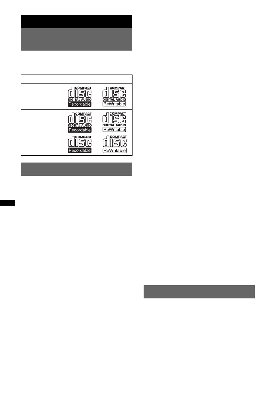
6
Procedimientos iniciales
Discos que se pueden
reproducir en esta unidad
Esta unidad puede reproducir discos CD-DA
(incluidos CD TEXT) y CD-R/CD-RW (archivos
MP3/WMA/AAC (página 26)).
Notas sobre Bluetooth
Precaución
SONY NO SERÁ RESPONSABLE DE NINGÚN
DAÑO INCIDENTAL, INDIRECTO O
DERIVADO NI DE OTROS DAÑOS
INCLUYENDO, SIN LÍMITES, PÉRDIDA DE
GANANCIAS, PÉRDIDA DE INGRESOS,
PÉRDIDAD DE DATOS, PÉRDIDA DE LA
UTILIDAD DEL PRODUCTO O DE
CUALQUIER EQUIPO RELACIONADO,
TIEMPO DE INACTIVIDAD NI TIEMPO DEL
COMPRADOR RELACIONADO CON O
RESULTANTE DE LA UTILIZACIÓN DE ESTE
PRODUCTO, SU HARDWARE Y/O SU
SOFTWARE.
AVISO IMPORTANTE
Utilización segura y eficaz
Los cambios o modificaciones que se realicen en
esta unidad sin la aprobación de Sony pueden anular
la autorización del usuario para utilizar el equipo.
Revise las excepciones, debido a requisitos
nacionales o limitaciones, en cuanto a la utilización
de los equipos Bluetooth antes de utilizar el equipo.
Manejo
Revise las leyes y normas acerca de la utilización de
teléfonos celulares y equipos de manos libres en las
áreas en las que maneja.
Preste siempre atención a la carretera y estacione el
automóvil antes de realizar o contestar una llamada
si las condiciones lo requieren.
Conexión a otros dispositivos
Al conectar el equipo a cualquier otro dispositivo,
lea el manual de instrucciones correspondiente para
obtener las instrucciones de seguridad.
Exposición a radiofrecuencia
Las señales de radiofrecuencia pueden afectar a los
sistemas electrónicos que no hayan sido instalados o
protegidos correctamente en automóviles, como los
sistemas electrónicos de inyección de combustible,
sistemas electrónicos de frenado antideslizante
(antibloqueo), sistemas electrónicos de control de
velocidad o sistemas de airbag. Para la instalación o
mantenimiento de este dispositivo, consulte al
fabricante de su automóvil o su representante. La
instalación o mantenimiento incorrectos podrían ser
peligrosos e invalidar cualquier garantía aplicada a
este dispositivo.
Consulte al fabricante de su automóvil para
asegurarse que el uso del teléfono celular en el
mismo no afectará su sistema electrónico.
Controle regularmente que todos los equipos del
dispositivo inalámbrico de su automóvil estén
instalados y funcionen correctamente.
Llamadas de emergencia
El dispositivo de manos libres Bluetooth para
automóviles y el dispositivo electrónico conectados
al manos libres funcionan utilizando redes de
señales de radio, celulares y terrestres así como
también la función programada por el usuario, que
no pueden garantizar la conexión bajo todas las
condiciones.
Por lo tanto, no dependa únicamente de un
dispositivo electrónico para las comunicaciones
esenciales (como las emergencias médicas).
Recuerde que, para realizar o recibir llamadas, el
dispositivo de manos libres y el dispositivo
electrónico conectado al manos libres deben operar
en una zona de servicio que tenga una intensidad de
señal para celulares adecuada.
Es posible que no se pueda realizar llamadas de
emergencia en todas las redes de teléfonos celulares
o cuando se estén utilizando ciertos servicios de la
red y/o características del teléfono.
Verifíquelo con su proveedor de servicio local.
Restauración de la unidad
Antes de utilizar la unidad por primera vez, o
después de sustituir la batería del automóvil o de
cambiar las conexiones, debe restaurarla.
Extraiga el panel frontal (página 7) y presione el
botón RESET (página 8) con un objeto
puntiagudo, como por ejemplo un bolígrafo.
Nota
Al presionar el botón RESET, se borrará el ajuste del
reloj y algunos contenidos memorizados.
Tipos de discos Etiqueta del disco
CD-DA
MP3
WMA
AAC
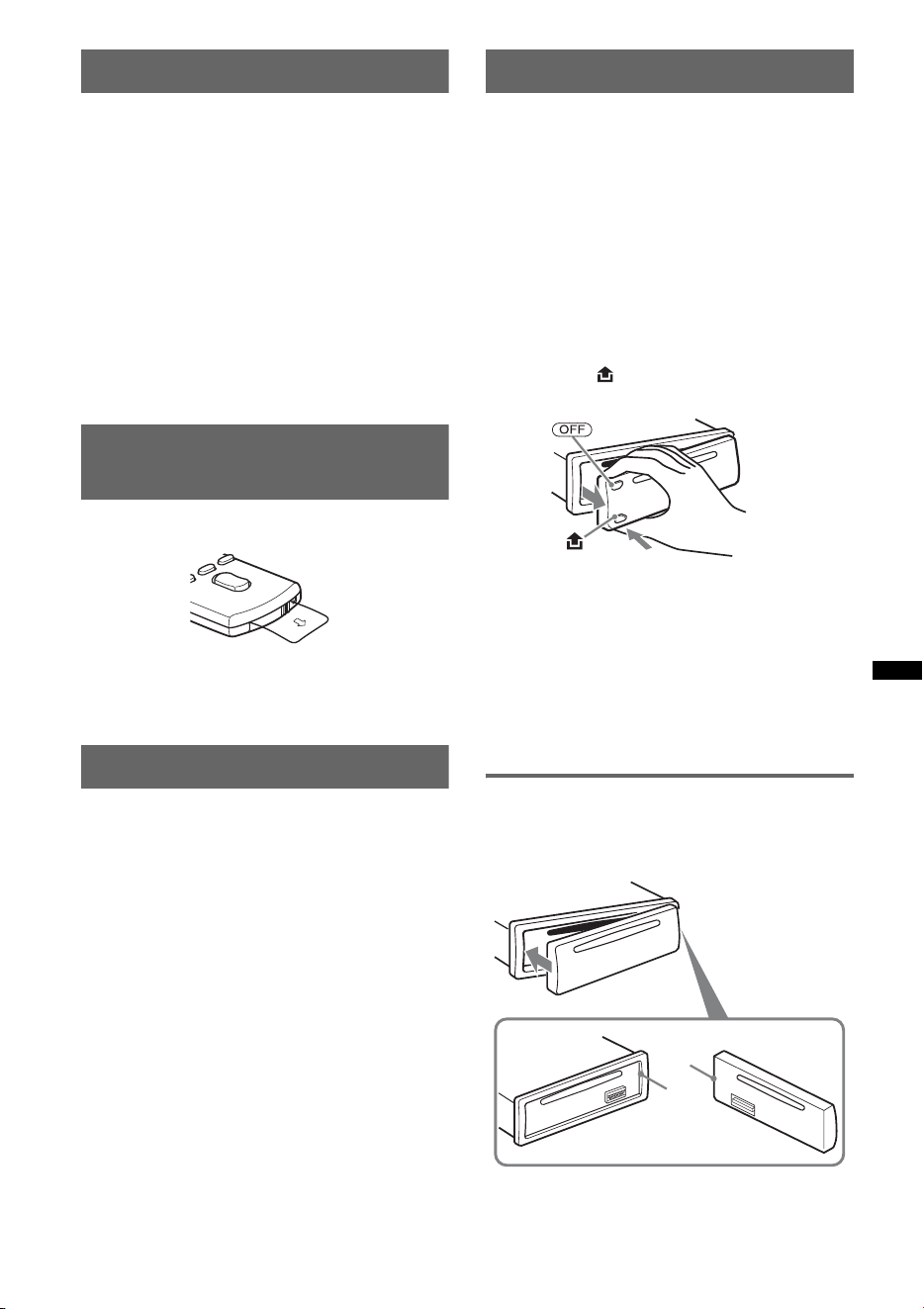
7
Cancelación del modo DEMO
Puede cancelar la pantalla de demostración que
aparece durante el apagado de la unidad.
1 Mantenga presionado el botón de
selección.
Aparecerá la pantalla de ajustes.
2 Presione el botón de selección varias
veces hasta que aparezca “DEMO”.
3 Gire el selector de control para
seleccionar “DEMO-OFF”.
4 Mantenga presionado el botón de
selección.
La configuración finaliza y la pantalla regresa
al modo de reproducción/recepción normal.
Preparación del control remoto
de tarjeta
Retire la película de aislamiento.
Sugerencia
Si desea obtener información adicional sobre cómo
sustituir la pila, consulte la página 27.
Ajuste del reloj
El reloj emplea una indicación digital de 12 horas.
1 Mantenga presionado el botón de
selección.
Aparecerá la pantalla de ajustes.
2 Presione el botón de selección varias
veces hasta que aparezca “CLOCK-
ADJ”.
3 Presione (SEEK) +.
La indicación de la hora parpadea.
4 Gire el selector de control para ajustar
la hora y los minutos.
Para mover la indicación digital, presione
(SEEK) +/–.
5 Tras ajustar los minutos, presione el
botón de selección.
El ajuste se completa y el reloj se pone en
funcionamiento.
Para mostrar el reloj, presione (DSPL). Vuelva a
presionar (DSPL) para regresar a la pantalla
anterior.
Extracción del panel frontal
Puede extraer el panel frontal de la unidad para
evitar que la roben.
Alarma de precaución
Si gira el interruptor de encendido hasta la
posición OFF sin haber extraído el panel frontal,
la alarma de precaución sonará durante unos
segundos.
La alarma sonará únicamente si se utiliza el
amplificador incorporado.
1 Presione (OFF).
La unidad se apaga.
2 Presione y luego extraiga el panel
frontal hacia usted.
Notas
• No deje caer ni ejerza excesiva presión sobre el
panel frontal ni la pantalla.
• No someta el panel frontal al calor ni a temperaturas
altas o excesiva humedad. Evite dejarlo en un
automóvil estacionado o sobre el tablero o la
bandeja trasera.
• No extraiga el panel frontal durante la reproducción
en el dispositivo USB, ya que podría dañar los datos
del USB.
Colocación del panel frontal
Fije la parte A del panel frontal en la parte B de
la unidad, tal como muestra la ilustración, y
presione el lado izquierdo hasta que encaje.
Nota
No coloque ningún objeto sobre la superficie interior
del panel frontal.
B
A
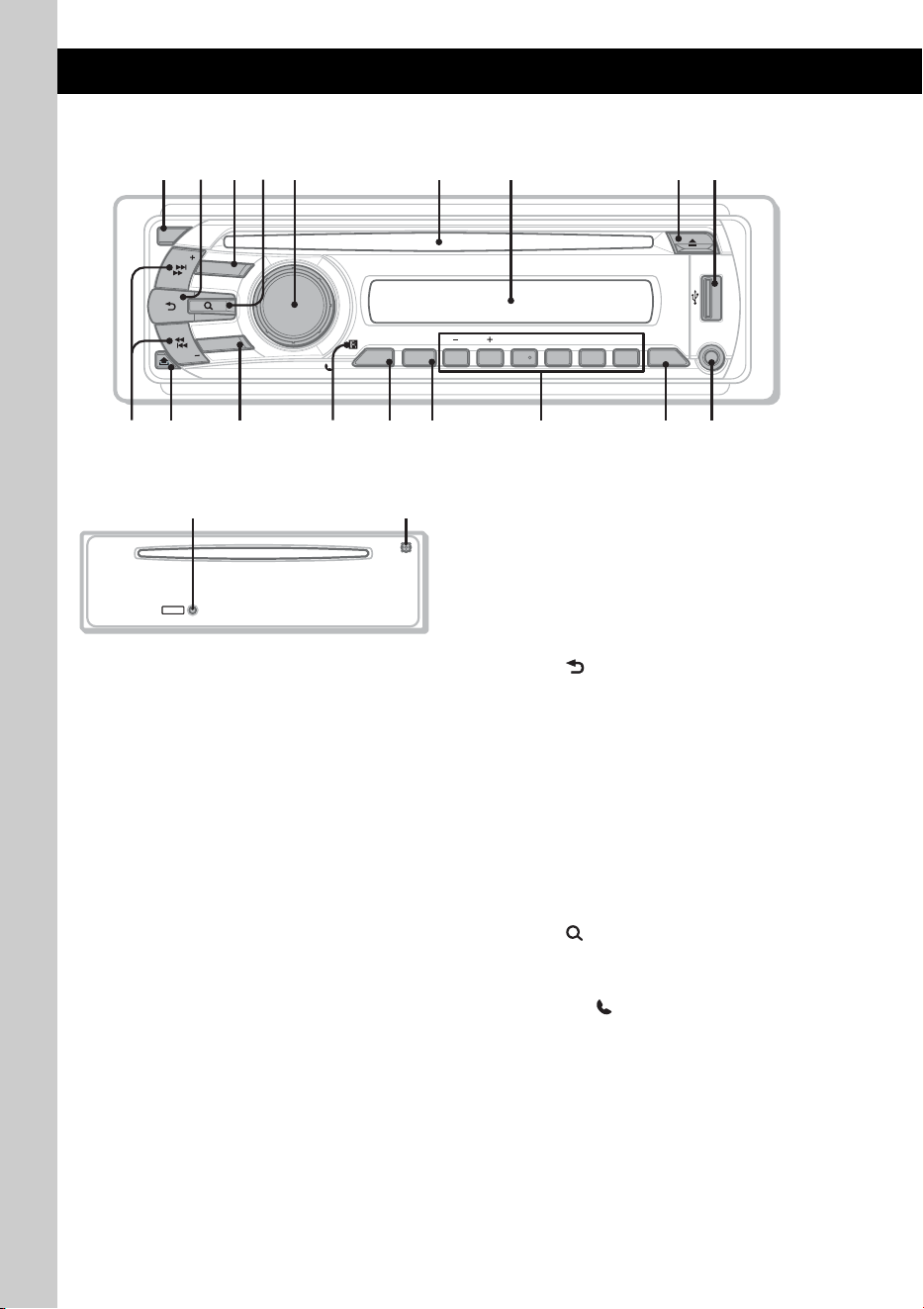
8
Ubicación de los controles y operaciones básicas
Unidad principal
Panel frontal extraído Este apartado contiene instrucciones acerca de la
ubicación de los controles y las operaciones
básicas. Si desea obtener más información,
consulte las páginas correspondientes.
Los botones correspondientes en el control
remoto de tarjeta controlan las mismas funciones
que los de la unidad.
A Botón OFF
Para apagar la unidad o detener la fuente.
B Botón (BACK)/MODE página 11,
12, 16, 17
Presionar para: regresar a la pantalla anterior,
seleccionar la banda de radio (FM/AM)*
1
o
seleccionar el modo de reproducción del
iPod.
Mantener presionado para: acceder al control
de pasajero o cancelar dicha función.
C Botón SOURCE
Para encender la unidad o cambiar la fuente
(Radio/CD/USB/AUX/audio Bluetooth/
teléfono Bluetooth)*
1
.
D Botón (BROWSE) página 11
Para acceder al modo Quick-BrowZer.
E Selector de control/botón de
selección/ (manos libres)
Para ajustar el volumen o seleccionar la
categoría de búsqueda (girar); para
seleccionar elementos de configuración
(presionar y girar); para recibir o finalizar
una llamada (presionar).
F Ranura del disco
Inserte el disco (con la etiqueta mirando
hacia arriba) y se iniciará la reproducción.
G Visualizador
ALBMARTISTRACK SHUF
+
DM
LOUDDISCREGTPTAAFZAP
AUX
BTMZAP
PAUSE
REP SHUF SCRL
OFF
1 2 3 4 5 6
ALBM
SOURCE
BT
BLUETOOTH
SEEK
SEEK
PUSH ENTER
/
SELECT
/
DSPL
MICCAT
MODE
1
q
a
q
;
9
2
q
s
q
j
q
k
q
g
4 65 7
8
3
q
h
q
f
q
d
RESET
w;ql

9
H Botón Z (expulsar)
Para expulsar el disco.
I Terminal USB página 14
Para conectar al dispositivo USB.
J Botones SEEK +/–
CD/USB:
Para omitir pistas (presionar); para omitir
pistas en forma continua (presionar y volver
a presionar dentro de 1 segundo y mantener
presionado); para retroceder o avanzar una
pista rápidamente (mantener presionado).
Radio:
Para sintonizar emisoras en forma
automática (presionar); para localizar una
emisora en forma manual (mantener
presionado).
Dispositivo de audio Bluetooth*
2
:
Para omitir pistas (presionar).
K Botón (extracción del panel
frontal) página 7
L Botón BT (BLUETOOTH) página 18
Para activar/desactivar la señal Bluetooth o
realizar el emparejamiento.
M Receptor del control remoto de tarjeta
N Botón ZAP página 12
Para acceder al modo ZAPPIN™.
O Botón BTM/CAT*
3
página 12
Para iniciar la función BTM (mantener
presionado).
P Botones numéricos
CD/USB:
(1)/(2): ALBM –/+ (durante la
reproducción de archivos MP3/WMA/AAC)
Para omitir álbumes (presionar); para
omitir álbumes en forma continua
(mantener presionado).
(3): REP página 13, 15, 16
(4): SHUF página 13, 15, 16
(6): PAUSE
Para hacer una pausa en la
reproducción. Para cancelar esta
función, vuelva a presionarlo.
Radio:
Para recibir las emisoras almacenadas
(presionar); para almacenar emisoras
(mantener presionado).
Dispositivo de audio Bluetooth*
2
:
(6): PAUSE
Para hacer una pausa en la
reproducción. Para cancelar esta
función, vuelva a presionarlo.
Teléfono Bluetooth:
(5): MIC página 19
Q Botón DSPL (pantalla)/SCRL
(desplazamiento) página 13, 14, 16, 17
Para cambiar los elementos de la pantalla
(presionar); para desplazar el elemento de la
pantalla (mantener presionado).
R Toma de entrada AUX página 23
Para conectar un dispositivo de audio
portátil.
S Botón RESET página 6
T Micrófono página 19
Nota
No cubra el micrófono. Si lo hace, es posible que
no pueda llamar con la función de manos libres.
*1 En el caso de que se encuentre conectado un
cambiador de CD, un sintonizador HD Radio o un
sintonizador SAT; al presionar (SOURCE), el
dispositivo conectado (“HD”, “XM” o “SR”)
aparecerá en la pantalla, en función del dispositivo
conectado. Además, si presiona (MODE), podrá
cambiar el cambiador, la banda del sintonizador
HD Radio o la banda del sintonizador SAT.
*2 Si se conecta un dispositivo de audio Bluetooth
(compatible con el AVRCP de la tecnología
Bluetooth). Según el tipo de dispositivo, hay
algunas operaciones que no se encuentran
disponibles.
*3 Si el sintonizador SAT se encuentra conectado.
Notas
• Al expulsar o insertar un disco, mantenga
desconectado cualquier dispositivo USB para evitar
dañar el disco.
• Si la unidad está apagada y desaparece la
indicación de pantalla, no se podrá utilizar con el
control remoto de tarjeta salvo que se presione
(SOURCE) en la unidad o se inserte un disco para
activarla en primer lugar.
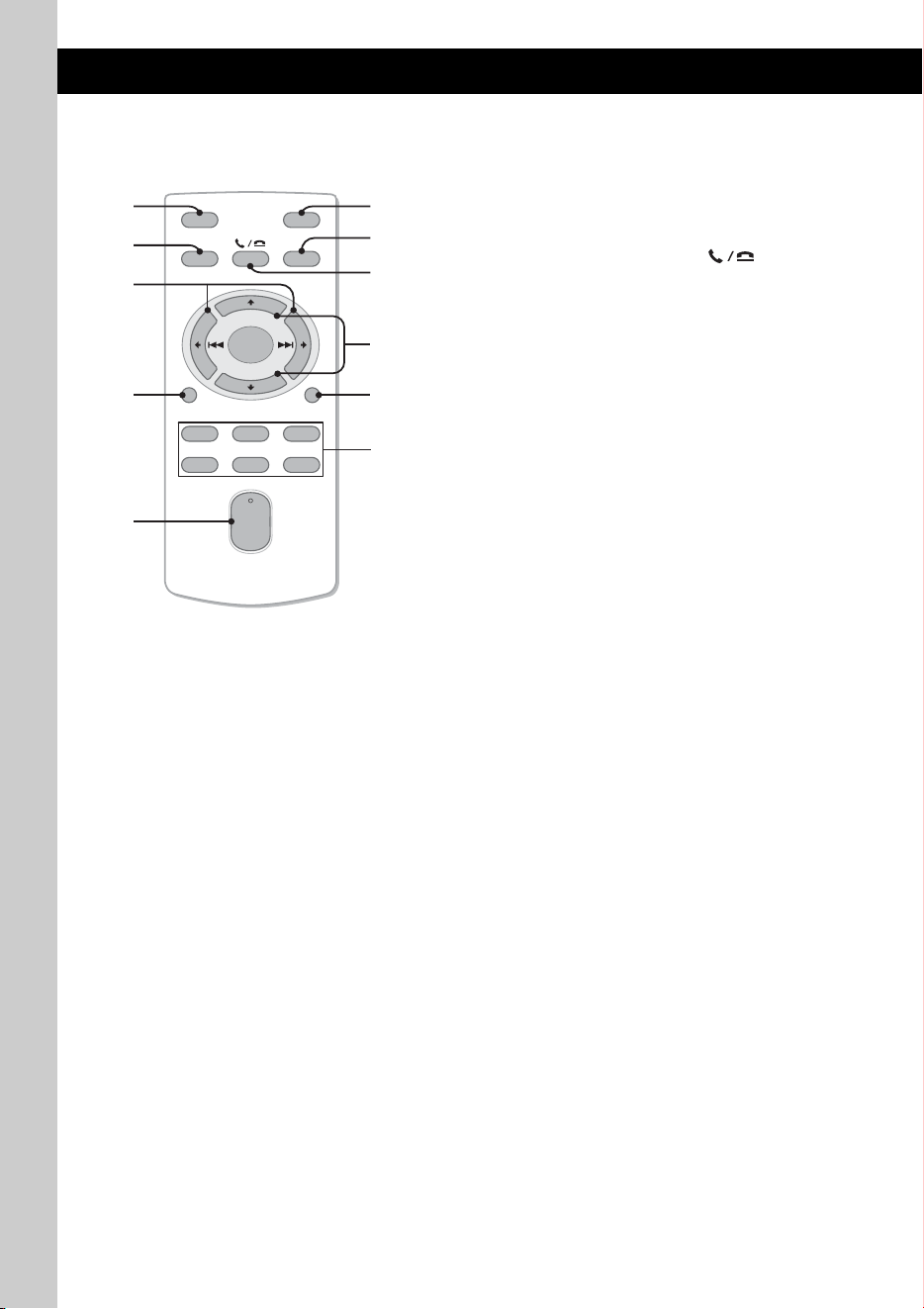
10
Control remoto de tarjeta
RM-X304
Algunos de los botones siguientes del control
remoto de tarjeta presentan distintas funciones o
difieren de los de la unidad. Retire la película de
aislamiento antes de utilizarlo (página 7).
A Botón OFF
Para apagar la unidad o detener la fuente.
B Botón SOURCE
Para encender la unidad o cambiar la fuente
(Radio/CD/USB/AUX/audio Bluetooth/
teléfono Bluetooth).
C Botones < (.)/, (>)
Permiten controlar la radio/CD/USB/audio
Bluetooth, de la misma manera que
(SEEK) –/+ en la unidad.
Es posible controlar la configuración, los
ajustes de sonido, etc. mediante < ,.
D Botón DSPL (pantalla)
Para cambiar los elementos en pantalla.
E Botón VOL (volumen) +/–
Para ajustar el volumen.
F Botón ATT (atenuación)
Para atenuar el sonido. Para cancelar esta
función, vuelva a presionarlo.
G Botón MODE
Presionar para: seleccionar la banda de radio
(FM/AM) o seleccionar el modo de
reproducción del iPod.
Mantener presionado para: acceder al control
de pasajero o cancelar dicha función.
H Botón SEL (selección)/ (manos
libres)
Funciona igual que el botón de selección de
la unidad.
I Botones M (+)/m (–)
Para controlar el CD/USB, del mismo modo
que (1)/(2) (ALBM –/+) en la unidad.
Es posible controlar la configuración, los
ajustes de sonido, etc. mediante M m.
J Botón SCRL (desplazamiento)
Para desplazar el elemento de la pantalla.
K Botones numéricos
Para recibir las emisoras almacenadas
(presionar); para almacenar emisoras
(mantener presionado).
OFF
DSPL
SCRL
SEL
SOURCE
MODE
132
465
ATT
VOL
+
–
+
–
2
8
7
1
0
3
6
5
4
qa
9
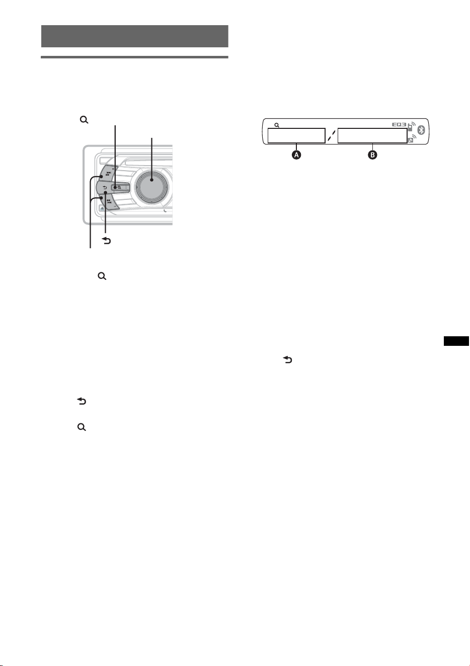
11
Búsqueda de una pista
Búsqueda de una pista por nombre
— Quick-BrowZer
Puede buscar una pista en un CD o dispositivo
USB fácilmente por categoría.
1 Presione (BROWSE).
La unidad accede al modo Quick-BrowZer y
aparece la lista de categorías de búsqueda.
2 Gire el selector de control para
seleccionar la categoría de búsqueda
deseada y, a continuación, presiónelo
para confirmarla.
3 Repita el paso 2 hasta que se
seleccione la pista deseada.
Se inicia la reproducción.
Para volver a la pantalla anterior
Presione (BACK).
Para salir del modo Quick-BrowZer
Presione (BROWSE).
Nota
Al acceder al modo Quick-BrowZer, se cancela el
ajuste de reproducción repetida/aleatoria.
Búsqueda mediante la omisión de
elementos — Modo Omitir
Si se encuentran muchos elementos en una
categoría, puede buscar el elemento deseado
rápidamente.
1 Presione (SEEK) + en el modo Quick-
BrowZer.
Aparecerá la siguiente pantalla.
A Número de elemento actual
B Número total de elementos en la capa actual
A continuación, aparecerá el nombre del
elemento.
2 Gire el selector de control para seleccionar el
elemento deseado o uno cercano a este.
El desplazamiento se realizará en intervalos
del 10% del número total de elementos.
3 Presione el botón de selección.
La pantalla volverá al modo Quick-BrowZer y
aparecerá el elemento seleccionado.
4 Gire el selector de control para seleccionar el
elemento deseado y presiónelo.
Si el elemento seleccionado es una pista, se
iniciará la reproducción.
Para cancelar el modo Omitir
Presione (BACK) o (SEEK) –.
OFF
S
O
U
R
C
E
SEEK
S
E
E
K
B
T
BLUETOOTH
PUSH ENTER
/
SELECT
/
MODE
(BROWSE)
Selector de control/
botón de selección
(BACK)
SEEK +/–
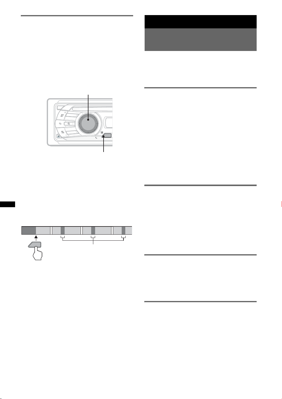
12
Búsqueda de una pista mediante la
escucha de pasajes de pistas
— ZAPPIN™
Durante la reproducción de cortos pasajes de las
pistas de un dispositivo CD o USB de forma
secuencial, podrá buscar la pista que desea
escuchar.
El modo ZAPPIN es adecuado para la búsqueda
de una pista en modo de reproducción aleatoria o
de reproducción repetida y aleatoria.
1 Presione (ZAP) durante la
reproducción.
Desde el momento en que “ZAPPIN” aparece
en la pantalla, la reproducción se inicia desde
el pasaje de la pista siguiente.
El pasaje se reproduce durante un tiempo
establecido y, a continuación, suena un clic y
se inicia el pasaje siguiente.
2 Presione el botón de selección o
(ZAP) cuando se reproduzca la pista
que desea escuchar.
La pista seleccionada volverá al modo de
reproducción normal y se reproducirá desde
el principio.
Para buscar una pista mediante el modo
ZAPPIN de nuevo, repita los pasos 1 y 2.
Sugerencias
• Puede seleccionar el tiempo de reproducción entre
6 segundos/9 segundos/30 segundos (página 22).
No es posible seleccionar el pasaje de la pista que
desea reproducir.
• Presione (SEEK) –/+ o (1)/(2) (ALBM –/+) en el
modo ZAPPIN para omitir una pista o álbum.
Radio
Almacenamiento y recepción
de emisoras
Precaución
Para sintonizar emisoras mientras maneja, utilice
la función BTM (Memoria de la mejor sintonía)
para evitar accidentes.
Almacenamiento automático
— BTM
1 Presione (SOURCE) varias veces hasta
que aparezca “TUNER”.
Para cambiar de banda, presione (MODE)
varias veces. Puede seleccionar entre FM1,
FM2, FM3, AM1 o AM2.
2 Mantenga presionado (BTM) hasta
que “BTM” parpadee.
La unidad almacena las emisoras en el orden
de frecuencia en los botones numéricos.
La unidad emite un pitido al almacenar el
ajuste.
Almacenamiento manual
1 Mientras recibe la emisora que desea
almacenar, mantenga presionado un
botón numérico (de (1) a (6)) hasta
que aparezca “MEM”.
Nota
Si intenta almacenar otra emisora en el mismo botón
numérico, se reemplazará la que estaba almacenada
previamente.
Recepción de las emisoras
almacenadas
1 Seleccione la banda y, a continuación,
presione un botón numérico (de (1) a
(6)).
Sintonización automática
1 Seleccione la banda y, a continuación,
presione (SEEK) +/– para buscar la
emisora.
La búsqueda se detiene cuando la unidad
recibe una emisora. Repita este
procedimiento hasta recibir la emisora
deseada.
ZAP
OFF
S
O
U
R
C
E
SEEK
S
E
E
K
B
T
BLUETOOTH
PUSH ENTER
/
SELECT
/
MODEMODE
ZAP
Botón de selección
ZAP
1
1
2
2
3
3
4
4
La parte de cada pista que se
reproducirá en el modo ZAPPIN.
Pista
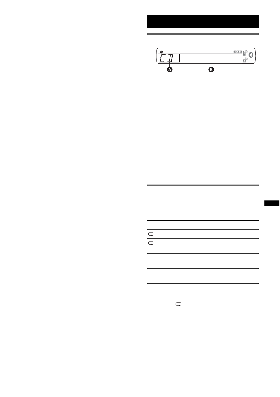
13
Sugerencia
Si conoce la frecuencia de la emisora que desea
escuchar, mantenga presionado (SEEK) +/– para
localizar la frecuencia aproximada y, a continuación,
presione (SEEK) +/– varias veces para ajustar la
frecuencia deseada con mayor precisión
(sintonización manual).
CD
Elementos de la pantalla
A Fuente
B Nombre de la pista*
1
, Nombre del disco/
artista*
1
, Nombre del artista*
1
, Número de
álbum*
2
, Nombre del álbum*
1
, Número de
pista/Tiempo de reproducción transcurrido,
Reloj
*1 Se muestra la información de un CD TEXT o
soporte con formato MP3/WMA/AAC.
*2 El número del álbum se muestra solamente
cuando se cambia de álbum.
Para cambiar los elementos de la pantalla B,
presione (DSPL).
Sugerencia
Los elementos que se muestran variarán en función
del tipo de disco, el formato de grabación y los
ajustes.
Reproducción repetida y aleatoria
1 Durante la reproducción, presione
(3) (REP) o (4) (SHUF) varias veces
hasta que aparezca el ajuste deseado.
* Si se reproduce un archivo MP3/WMA/AAC.
Para volver al modo de reproducción normal,
seleccione “ OFF” o “SHUF OFF”.
Seleccione Para reproducir
TRACK pistas en forma repetida.
ALBUM* álbumes en forma
repetida.
SHUF ALBUM* álbumes en orden
aleatorio.
SHUF DISC discos en orden
aleatorio.
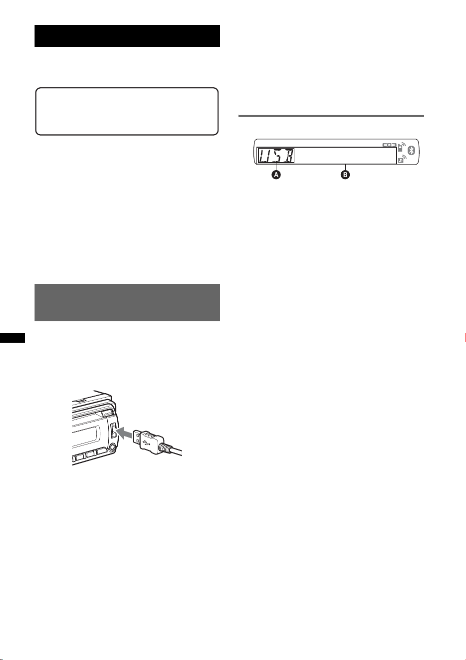
14
Dispositivos USB
Para obtener más información acerca de la
compatibilidad del dispositivo USB, visite el
sitio web de soporte técnico de Sony.
• Es posible utilizar dispositivos USB tipo MSC
(Mass Storage Class) y MTP (Media Transfer
Protocol) que cumplan con el estándar USB.
• El códec correspondiente es MP3 (.mp3),
WMA (.wma) y AAC (.m4a).
• Se recomienda realizar una copia de seguridad
de los datos almacenados en los dispositivos
USB.
Nota
Conecte el dispositivo USB tras encender el motor.
Según el dispositivo USB que utilice, es posible que
se produzca un mal funcionamiento o daños si se
conecta antes de encender el motor.
Reproducción de un dispositivo
USB
1 Conecte el dispositivo USB al terminal
USB.
Cuando utilice un cable, use el que se ha
suministrado para la conexión con el
dispositivo USB.
Se inicia la reproducción.
Si ya existe un dispositivo USB conectado,
presione (SOURCE) varias veces hasta que
aparezca “USB” para iniciar la reproducción.
Presione (OFF) para detener la reproducción.
Extracción del dispositivo USB
1 Detenga la reproducción del dispositivo USB.
2 Extraiga el dispositivo USB.
Si extrae el dispositivo USB durante la
reproducción, es posible que se dañe la
información que contiene.
Notas
• No utilice dispositivos USB demasiado grandes o
pesados, ya que pueden caer debido a la vibración
o provocar una conexión deficiente.
• No extraiga el panel frontal durante la reproducción
en el dispositivo USB, ya que podría dañar los datos
del USB.
• Esta unidad no puede reconocer dispositivos USB a
través de un concentrador USB.
Elementos de la pantalla
A Fuente
B Nombre de la pista, Nombre del artista,
Número de álbum*, Nombre del álbum,
Número de pista/Tiempo de reproducción
transcurrido, Reloj
* El número del álbum se muestra solamente cuando
se cambia de álbum.
Para cambiar los elementos de la pantalla B,
presione (DSPL).
Notas
• Los elementos que se muestran variarán en función
del tipo de dispositivo USB, el formato de grabación
y los ajustes. Para obtener más información, visite el
sitio web de soporte técnico.
• El número máximo de datos que se pueden
visualizar es el siguiente.
– carpetas (álbumes): 128
– archivos (pistas) por carpeta: 500
• No deje un dispositivo USB dentro de un automóvil
estacionado, ya que podrían producirse fallas de
funcionamiento.
• Es posible que el inicio de la reproducción demore
un poco, en función de la cantidad de datos
grabados.
• Es posible que no pueda reproducir archivos DRM
(Gestión de derechos digitales).
• Durante la reproducción de un archivo MP3/WMA/
AAC de VBR (Velocidad de bits variable) o al
avanzar o retroceder rápidamente, es posible que el
tiempo de reproducción transcurrido no se muestre
con precisión.
• No es posible reproducir los archivos MP3/WMA/
AAC que se indican a continuación.
– archivos con formato de compresión sin pérdida
– archivos protegidos por derechos de autor
Sitio Web de soporte técnico en línea
http://esupport.sony.com
http://www.xplodsony.com/
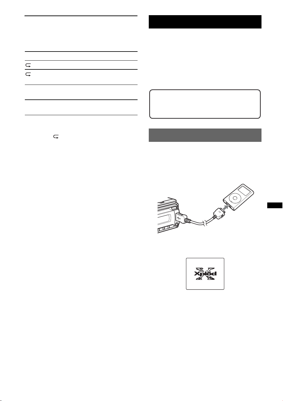
15
Reproducción repetida y aleatoria
1 Durante la reproducción, presione
(3) (REP) o (4) (SHUF) varias veces
hasta que aparezca el ajuste deseado.
Después de 3 segundos, finaliza el ajuste.
Para volver al modo de reproducción normal,
seleccione “ OFF” o “SHUF OFF”.
iPod
Para obtener más información acerca de la
compatibilidad del iPod, consulte “Acerca de
iPod” en la página 26 o visite el sitio web de
soporte técnico de Sony.
En este manual de instrucciones, “iPod” se
utiliza como referencia general para las
funciones de iPod de los dispositivos iPod e
iPhone, si no se especifica lo contrario en el texto
o las ilustraciones.
Reproducción de un iPod
Antes de conectar el iPod, baje el volumen de la
unidad.
1 Conecte el iPod al terminal USB
mediante el conector de base al cable
USB.
El iPod se activará automáticamente y
aparecerá la visualización que se muestra a
continuación en la pantalla del iPod.*
Sugerencia
Se recomienda el uso del cable RC-100IP USB (no
suministrado) para conectar el conector de base.
Las pistas del iPod empiezan a reproducirse
automáticamente desde el punto de la última
reproducción.
Si ya existe un dispositivo iPod conectado,
presione (SOURCE) varias veces hasta que
aparezca “USB” para iniciar la reproducción.
(“IPD” aparecerá en la pantalla cuando se
reconozca el iPod.)
Seleccione Para reproducir
TRACK pistas en forma repetida.
ALBUM álbumes en forma
repetida.
SHUF ALBUM álbumes en orden
aleatorio.
SHUF DEVICE dispositivos en orden
aleatorio.
continúa en la página siguiente t
Sitio Web de soporte técnico en línea
http://esupport.sony.com
http://www.xplodsony.com/
>
.
M
E
N
U
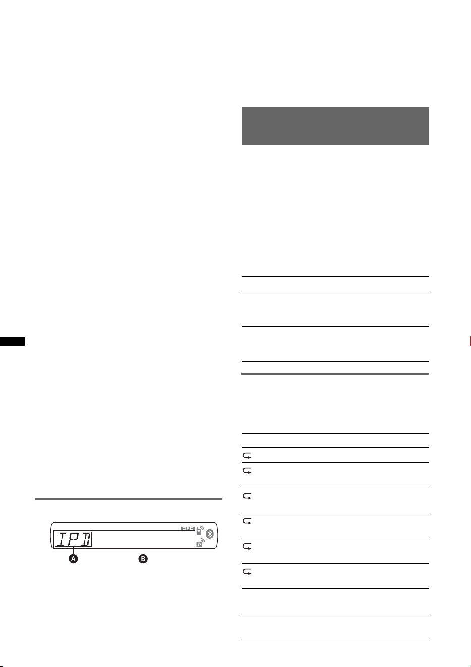
16
* Si se reprodujo el contenido del iPod en el modo de
control de pasajero la última vez, no aparecerá este
indicador.
2 Presione (MODE) para seleccionar el
modo de reproducción.
El modo cambia de la manera siguiente:
RESUMING t ALBUM t TRACK t
PODCAST* t GENRE t PLAYLIST
t ARTIST
* Es posible que no aparezca según los ajustes del
iPod.
3 Ajuste el volumen.
Presione (OFF) para detener la reproducción.
Extracción del iPod
1 Detenga la reproducción del iPod.
2 Extraiga el iPod.
Precauciones para iPhone
Si conecta un iPhone mediante una conexión USB, el
propio iPhone controla el volumen del teléfono. Con el
fin de evitar un sonido estridente y repentino tras una
llamada, no aumente el volumen en la unidad durante
una llamada telefónica.
Notas
• No extraiga el panel frontal durante la reproducción
del iPod, ya que podría dañar los datos.
• Esta unidad no puede reconocer dispositivos iPod a
través de un concentrador USB.
Sugerencias
• Al ajustar la llave de encendido del automóvil en la
posición ACC (accesorios), y si la unidad se
encuentra encendida, es posible recargar el iPod.
• Si se desconecta el iPod durante la reproducción,
aparecerá “NO DEV” en la pantalla de la unidad.
Modo reanudación
Si el iPod se encuentra conectado al conector de
base, el modo de esta unidad cambia al modo
reanudación y la reproducción se inicia en el
modo ajustado por el iPod.
En el modo reanudación, los siguientes botones
no funcionan.
– (3) (REP)
– (4) (SHUF)
Elementos de la pantalla
A Indicación de fuente (iPod)
B Nombre de la pista, Nombre del artista,
Nombre del álbum, Número de pista/Tiempo
de reproducción transcurrido, Reloj
Para cambiar los elementos de la pantalla B,
presione (DSPL).
Sugerencia
Si se modifica un álbum, podcast, género, artista o
lista de reproducción, su número de elemento
aparece momentáneamente.
Nota
Es posible que algunos caracteres almacenados en el
iPod no se muestren correctamente.
Ajuste del modo de
reproducción
1 Durante la reproducción, presione
(MODE).
El modo cambia de la manera siguiente:
ALBUM t TRACK t PODCAST* t
GENRE t PLAYLIST t ARTIST
* Es posible que no aparezca según los ajustes del
iPod.
Omisión de álbumes, podcasts,
géneros, listas de reproducción y
artistas
Reproducción repetida y aleatoria
1 Durante la reproducción, presione
(3) (REP) o (4) (SHUF) varias veces
hasta que aparezca el ajuste deseado.
Para Presione
Omitir (1)/(2) (ALBM –/+)
[presionar una vez para cada
uno]
Omitir en
forma continua
(1)/(2) (ALBM –/+)
[mantener presionado hasta el
punto deseado]
Seleccione Para reproducir
TRACK pistas en forma repetida.
ALBUM álbumes en forma
repetida.
PODCAST podcast en forma
repetida.
ARTIST artistas en forma
repetida.
PLAYLIST listas de reproducción en
forma repetida.
GENRE géneros en forma
repetida.
SHUF ALBUM álbumes en orden
aleatorio.
SHUF PODCAST podcast en orden
aleatorio.
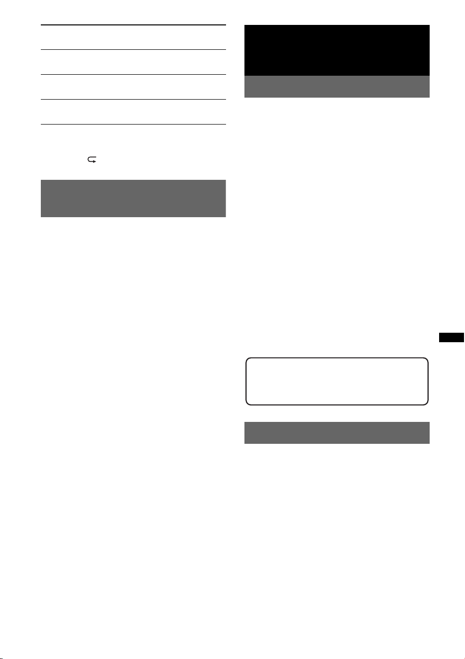
17
Después de 3 segundos, finaliza el ajuste.
Para volver al modo de reproducción normal,
seleccione “ OFF” o “SHUF OFF”.
Operación directa de un iPod
— Control de pasajero
Es posible operar directamente un iPod
conectado al conector de base.
1 Durante la reproducción, mantenga
presionado (MODE).
Aparecerá “MODE IPOD” y podrá operar el
iPod directamente.
Para cambiar los elementos en pantalla
Presione (DSPL).
Los elementos en pantalla cambian de la manera
siguiente:
Nombre de la pista t Nombre del artista t
Nombre del álbum t MODE IPOD t Reloj
Para salir del control de pasajero
Mantenga presionado (MODE).
A continuación, aparecerá “MODE AUDIO” y el
modo de reproducción cambiará a
“RESUMING”.
Notas
• Es posible ajustar el volumen únicamente desde la
unidad.
• Si se cancela este modo, el ajuste de repetición se
desactivará.
Bluetooth (Llamadas con
manos libres y transmisión
continua de música)
Operaciones Bluetooth
Para utilizar la función Bluetooth, es necesario
realizar el procedimiento siguiente.
1 Emparejamiento
Cuando dos dispositivos Bluetooth se
conectan por primera vez, se requiere un
registro mutuo. Esto se llama
“emparejamiento”. Solamente es necesario
realizar el registro (emparejamiento) la
primera vez, ya que, una vez emparejados, los
dispositivos se reconocerán entre sí
automáticamente. Es posible emparejar hasta
8 dispositivos. (Según el tipo de dispositivo,
es posible que necesite ingresar una
contraseña para cada conexión.)
2 Conexión
Para utilizar el dispositivo después de llevar a
cabo el emparejamiento, inicie la conexión.
En ocasiones, el emparejamiento permite
establecer la conexión automáticamente.
3 Llamadas con manos libres/
Transmisión continua de música
Puede iniciar una conversación con manos
libres y escuchar música después de
establecer la conexión.
Emparejamiento
Primero, registre (“empareje”) un dispositivo
Bluetooth (teléfono celular, etc.) y esta unidad.
Es posible emparejar hasta 8 dispositivos.
Después de establecer el emparejamiento, no
será necesario volver a realizarlo.
1 Coloque el dispositivo Bluetooth a una
distancia máxima de 1 metro respecto
de la unidad.
SHUF ARTIST artistas en orden
aleatorio.
SHUF PLAYLIST listas de reproducción en
orden aleatorio.
SHUF GENRE géneros en orden
aleatorio.
SHUF DEVICE dispositivos en orden
aleatorio.
continúa en la página siguiente t
Sitio Web de soporte técnico en línea
http://esupport.sony.com
http://www.xplodsony.com/
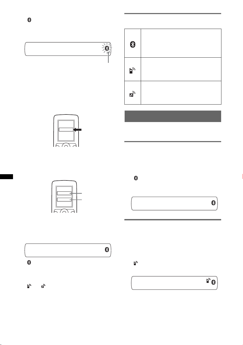
18
2 Mantenga presionado (BT) hasta que
“ ” parpadee (aproximadamente 5
segundos).
La unidad entrará en modo de espera de
emparejamiento.
3 Ajuste el dispositivo Bluetooth para
que busque esta unidad.
Aparece una lista de los dispositivos
detectados en la pantalla del dispositivo que
desea conectar. La unidad se muestra como
“XPLOD” en el dispositivo que se va a
conectar.
4 Si se requiere introducir la
contraseña* en la pantalla del
dispositivo que se va a conectar,
especifique “0000”.
Esta unidad y el dispositivo Bluetooth
memorizan la información entre sí y, después
de realizar el emparejamiento, la unidad está
preparada para conectarse al dispositivo.
“ ” parpadea y, cuando se ha establecido la
conexión, pasa a permanecer encendido.
5 Ajuste el dispositivo Bluetooth para
conectarlo a esta unidad.
“ ” o “ ” aparece cuando se ha realizado la
conexión.
* La contraseña puede denominarse “passkey”, “PIN
code”, “PIN number” o “Password”, etc., según el
tipo de dispositivo.
Nota
El modo de espera de emparejamiento no se cancela
hasta que se ha establecido la conexión.
Acerca de los iconos Bluetooth
En esta unidad, se utilizan los iconos siguientes.
Conexión
Si ha conseguido realizar el emparejamiento,
inicie la operación a partir de este punto.
Para activar la salida de la señal
Bluetooth de esta unidad
Puede utilizar la función Bluetooth para activar
la salida de la señal Bluetooth de esta unidad.
1 Mantenga presionado (BT) hasta que
“ ” se ilumine (aproximadamente 3
segundos).
La señal Bluetooth se activará.
Conexión a un teléfono celular
1 Asegúrese de que tanto esta unidad
como el teléfono celular tienen la
señal Bluetooth activada.
2 Realice la conexión a esta unidad
mediante el teléfono celular.
“ ”aparece cuando se ha realizado la
conexión.
parpadea
XXXXXXX
DR-BT30Q
XPLOD
XXXX
Contraseña
introducida.
“0000”
encendido:
parpadea:
apagado:
señal Bluetooth activa
modo de espera de
emparejamiento
señal Bluetooth
desactivada
encendido:
parpadea:
apagado:
conexión establecida
correctamente
conexión en curso
sin conexión
encendido:
parpadea:
apagado:
conexión establecida
correctamente
conexión en curso
sin conexión
19
Conexión del último teléfono celular
conectado desde esta unidad
1 Asegúrese de que tanto esta unidad como el
teléfono celular tienen la señal Bluetooth
activada.
2 Presione (SOURCE) varias veces hasta que
aparezca “BT PHONE”.
3 Presione (manos libres).
“ ” parpadea mientras se establece la
conexión. A continuación, “ ” pasa a
permanecer encendido cuando se ha
establecido la conexión.
Nota
Durante la transmisión continua de audio Bluetooth,
no es posible establecer una conexión desde esta
unidad al teléfono celular. Realice la conexión desde
el teléfono celular a esta unidad en su lugar. Es
posible que se escuche un ruido de conexión
superpuesto al sonido de reproducción.
Sugerencia
Con la señal Bluetooth activada: cuando el encendido
se ajusta en la posición ON, la unidad vuelve a
conectarse automáticamente al último teléfono celular
conectado. La conexión automática también depende
de la especificación del teléfono celular. Si la unidad
no vuelve a conectarse automáticamente, conéctela
manualmente.
Conexión a un dispositivo de audio
1 Compruebe que esta unidad y el
dispositivo de audio tengan la señal
Bluetooth activada.
2 Realice la conexión a esta unidad
mediante el dispositivo de audio.
“ ” aparece cuando se ha realizado la
conexión.
Conexión del último dispositivo de
audio conectado desde esta unidad
1 Compruebe que esta unidad y el dispositivo de
audio tengan la señal Bluetooth activada.
2 Presione (SOURCE) varias veces hasta que
aparezca “BT AUDIO”.
3 Presione (6).
“ ” parpadea mientras se establece la
conexión. A continuación, “ ” pasa a
permanecer encendido cuando se ha
establecido la conexión.
Realización de llamadas con
manos libres
Para empezar, compruebe que esta unidad y el
teléfono celular estén conectados.
Recepción de llamadas
Cuando se recibe una llamada, se emite un tono
de llamada a través de los altavoces de su
automóvil.
1 Presione (manos libres) al recibir
una llamada con un tono de llamada.
Comienza la llamada telefónica.
Para finalizar una llamada
Presione de nuevo (manos libres) u (OFF).
Para rechazar una llamada entrante, mantenga
presionado (manos libres) durante 2 segundos.
Ajuste de la ganancia del micrófono
Puede alternar entre dos niveles de volumen
(“LOW” o “HI”) para ajustar un nivel adecuado
para el interlocutor durante una llamada.
1 Presione (5) durante una llamada.
El elemento cambia de la manera siguiente:
MIC-LOW y MIC-HI
Nota
El micrófono de esta unidad se encuentra en la parte
posterior del panel frontal (página 8). No cubra el
micrófono con cinta, etc.
Realización de llamadas
En el caso de realizar llamadas desde esta
unidad, se utiliza la remarcación.
1 Presione (SOURCE) varias veces hasta
que aparezca “BT PHONE”.
2 Mantenga presionado (manos
libres) durante al menos 3 segundos.
Comienza la llamada telefónica.
Para finalizar una llamada
Presione de nuevo (manos libres) u (OFF).
Para llamar a otro teléfono, utilice el teléfono
celular y, a continuación, transfiera la llamada.
Para obtener más información sobre la
transferencia, consulte lo siguiente.

20
Transferencia de llamadas
Con el fin de activar o desactivar el dispositivo
correcto (esta unidad o el teléfono celular),
compruebe lo siguiente.
1 Mantenga presionado (manos
libres) o utilice el teléfono celular.
Para obtener más información acerca del
funcionamiento del teléfono celular, consulte el
manual de instrucciones de dicho dispositivo.
Nota
En función del teléfono celular, es posible que la
conexión se interrumpa al intentar transferir una
llamada.
Activación de la marcación por voz
Para activar la marcación por voz con un teléfono
celular conectado a esta unidad, mencione la
etiqueta de voz almacenada en el teléfono celular
y, a continuación, realice la llamada.
1 Presione (SOURCE) varias veces hasta
que aparezca “BT PHONE”.
2 Presione (manos libres).
El teléfono celular entra en el modo de
marcación por voz.
3 Mencione la etiqueta de voz
almacenada en el teléfono celular.
Se reconocerá su voz y se realizará la
llamada.
Notas
• Para empezar, compruebe que la unidad y el
teléfono celular estén conectados.
• Almacene una etiqueta de voz en el teléfono celular
de antemano.
• Si activa la marcación por voz con un teléfono
celular conectado a la unidad, es posible que esta
función no esté disponible en algunos casos.
• Los ruidos, como el del motor en marcha, pueden
interferir en el reconocimiento del sonido. Para
mejorar el reconocimiento, utilice la unidad en
condiciones en que el ruido sea mínimo.
• Es posible que la marcación por voz no funcione en
algunas situaciones, en función de la eficacia de la
función de reconocimiento de voz del teléfono
celular. Para obtener más información, consulte el
sitio web de asistencia al cliente (página 30).
Sugerencias
• Hable del mismo modo que cuando almacenó la
etiqueta de voz.
• Almacene una etiqueta de voz mientras se
encuentra sentado en el automóvil, a través de esta
unidad y con la fuente “BT PHONE” seleccionada.
Transmisión continua de
música
Escuchar música desde un
dispositivo de audio
Esta unidad permite escuchar música de un
dispositivo de audio si el dispositivo de audio es
compatible con A2DP (Advanced Audio
Distribution Profile) de la tecnología Bluetooth.
1 Baje el volumen de esta unidad.
2 Presione (SOURCE) varias veces hasta
que aparezca “BT AUDIO”.
3 Para comenzar la reproducción utilice
las funciones del dispositivo de audio.
4 Ajuste el volumen en la unidad.
Ajuste del nivel de volumen
El nivel de volumen puede regularse para ajustar
cualquier diferencia existente entre la unidad y el
dispositivo de audio Bluetooth.
1 Inicie la reproducción en el dispositivo de
audio Bluetooth con un volumen moderado.
2 Seleccione el volumen habitual en la unidad.
3 Presione el botón de selección varias veces
hasta que aparezca “BTA” y gire el selector de
control de volumen para ajustar el nivel de
entrada (de –8 dB a +18 dB).
Operación de un dispositivo de
audio con esta unidad
Puede realizar las siguientes operaciones en esta
unidad si el dispositivo de audio es compatible
con AVRCP (Audio Video Remote Control
Profile) de la tecnología Bluetooth. (La
operación puede variar en función del tipo de
dispositivo de audio).
* Según el tipo de dispositivo, es posible que sea
necesario presionar dos veces.
Cualquier otra operación se debe realizar
directamente en el dispositivo de audio.
Para Presione
Reproducir (6) (PAUSE)* en la unidad.
Insertar una
pausa
(6) (PAUSE)* en la unidad.
Omitir pistas SEEK –/+ (
./>) [una vez
para cada pista]
21
Notas
• Durante la reproducción en el dispositivo de audio,
algunos datos como, por ejemplo, el número de
pista y la duración, el estado de la reproducción, etc.
de un dispositivo de audio conectado no se
mostrarán en la unidad.
• Es posible cambiar la fuente en la unidad sin que se
interrumpa la reproducción de la señal del
dispositivo de audio.
Sugerencia
Puede conectar un teléfono celular que admita A2DP
(Advanced Audio Distribution Profile) como dispositivo
de audio y escuchar música.
Eliminación del registro de
todos los dispositivos
emparejados
1 Presione (OFF).
La unidad se apaga.
2 Si “ ” se ilumina, mantenga
presionado (BT) hasta que “ ” se
apague.
3 Mantenga presionado el botón de
selección.
4 Presione el botón de selección varias
veces hasta que aparezca “BT INIT”.
5 Presione (SEEK) +.
Comenzará la inicialización.
La cancelación de todos los registros tarda
3 segundos. No apague la alimentación
mientras “INITIAL” esté parpadeando.
Otras funciones
Cambio de los ajustes de
sonido
Ajuste de las características del
sonido
1 Presione el botón de selección varias
veces hasta que aparezca el elemento
deseado.
2 Gire el selector de control para ajustar
el elemento seleccionado.
3 Presione (BACK).
El ajuste finaliza y la pantalla regresa al modo
de reproducción/recepción normal.
Se pueden ajustar los elementos siguientes
(consulte la referencia de página para obtener
más información):
EQ3
Selecciona una curva de ecualizador entre
7 tipos de música distintos.
LOW*
1
, MID*
1
, HI*
1
(página 22)
BAL (Balance)
Permite ajustar el balance de sonido entre los
altavoces izquierdo y derecho.
FAD (Equilibrio)
Permite ajustar el nivel relativo entre los
altavoces frontal y posterior.
SUB (Volumen del altavoz potenciador de
graves)
Permite ajustar el volumen del altavoz
potenciador de graves.
(“ATT” es el ajuste más bajo).
AUX*
2
(Nivel AUX)
Permite ajustar el nivel de volumen de cada
equipo auxiliar conectado: “+18 dB” – “0 dB” –
“–8 dB”.
Este ajuste elimina la necesidad de ajustar el
nivel de volumen entre fuentes.
BTA*
3
(Nivel de audio BT)
Permite ajustar el nivel de volumen de cada uno
de los dispositivos de audio Bluetooth
conectados: “+18 dB” – “0 dB” – “–8 dB”.
Este ajuste elimina la necesidad de ajustar el
nivel de volumen entre fuentes (página 20).
*1 Si está activado EQ3.
*2 Si está activada la fuente AUX.
*3 Si la fuente de audio Bluetooth está activada
(página 20).
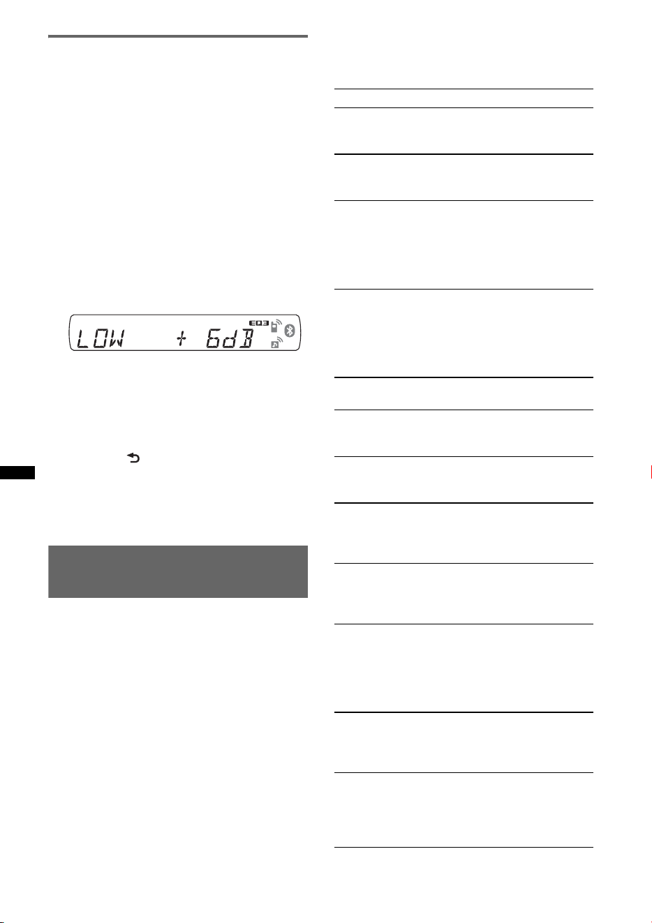
22
Personalización de la curva de
ecualizador — EQ3
“CUSTOM” de EQ3 le permite realizar sus
propios ajustes de ecualizador.
1 Seleccione una fuente y presione el
botón de selección varias veces para
seleccionar “EQ3”.
2 Gire el selector de control para
seleccionar “CUSTOM”.
3 Presione el botón de selección varias
veces hasta que aparezca “LOW”,
“MID” o “HI”.
4 Gire el selector de control para ajustar
el elemento seleccionado.
El nivel de volumen puede ajustarse en
intervalos de 1 dB, entre –10 dB y +10 dB.
Repita los pasos 3 y 4 para ajustar la curva de
ecualizador.
Para restaurar la curva de ecualizador
ajustada en fábrica, mantenga presionado el
botón de selección antes de que finalice el
ajuste.
5 Presione (BACK).
El ajuste finaliza y la pantalla regresa al modo
de reproducción/recepción normal.
Sugerencia
También es posible ajustar otros tipos de ecualizador.
Definición de los elementos de
configuración — SET
1 Mantenga presionado el botón de
selección.
Aparecerá la pantalla de ajustes.
2 Presione el botón de selección varias
veces hasta que aparezca el elemento
deseado.
3 Gire el selector de control para
seleccionar el ajuste (por ejemplo,
“ON” u “OFF”).
4 Mantenga presionado el botón de
selección.
La configuración finaliza y la pantalla regresa
al modo de reproducción/recepción normal.
Nota
Los elementos que se muestran en pantalla variarán
en función de la fuente y del ajuste.
Se pueden ajustar los elementos siguientes
(consulte la referencia de página para obtener
más información):
CLOCK-ADJ (Ajuste del reloj) (página 7)
BEEP
Permite activar el sonido de los pitidos: “ON”,
“OFF”.
AUX-A*
1
(Audio AUX)
Permite activar la pantalla de la fuente AUX:
“ON”, “OFF” (página 23).
A.OFF
Permite cortar la alimentación automáticamente
una vez transcurrido un período de tiempo
deseado cuando la unidad está apagada: “NO”,
“30S (segundos)”, “30M (minutos)”, “60M
(minutos)”.
MIC*
1
– “EXT”: para cambiar automáticamente al
micrófono externo cuando éste se encuentra
conectado.
– “INT”: para seleccionar únicamente el
micrófono interno.
DEMO
(Demostración)
Permite activar la demostración: “ON”, “OFF”.
DIM (Atenuador)
Permite cambiar el brillo de la pantalla: “ON”,
“OFF”.
A.SCRL*
2
(Desplazamiento automático)
Permite desplazar automáticamente los
elementos largos de la pantalla: “ON”, “OFF”.
LOCAL (Modo de búsqueda local)
– “ON”: para que se sintonicen solamente las
emisoras de señal más intensa.
– “OFF”: para ajustar la recepción normal.
MONO*
3
(Modo monoaural)
Permite seleccionar el modo de recepción
monoaural para mejorar las recepciones de FM
deficientes: “ON”, “OFF”.
Z.TIME*
2
(Tiempo de Zappin)
Permite seleccionar el tiempo de reproducción
para la función ZAPPIN.
– “Z.TIME-1 (unos 6 segundos)”, “Z.TIME-2
(unos 9 segundos)”, “Z.TIME-3 (unos
30 segundos)”.
LPF (Filtro de paso bajo)
Permite seleccionar la frecuencia de corte del
altavoz potenciador de graves: “OFF”, “80Hz”,
“100Hz”, “120Hz”, “140Hz”, “160Hz”.
LPF NORM/REV (Filtro de paso bajo Normal/
Inversa)
Permite seleccionar la fase cuando el filtro de
paso bajo se encuentra activado: “NORM”,
“REV”.
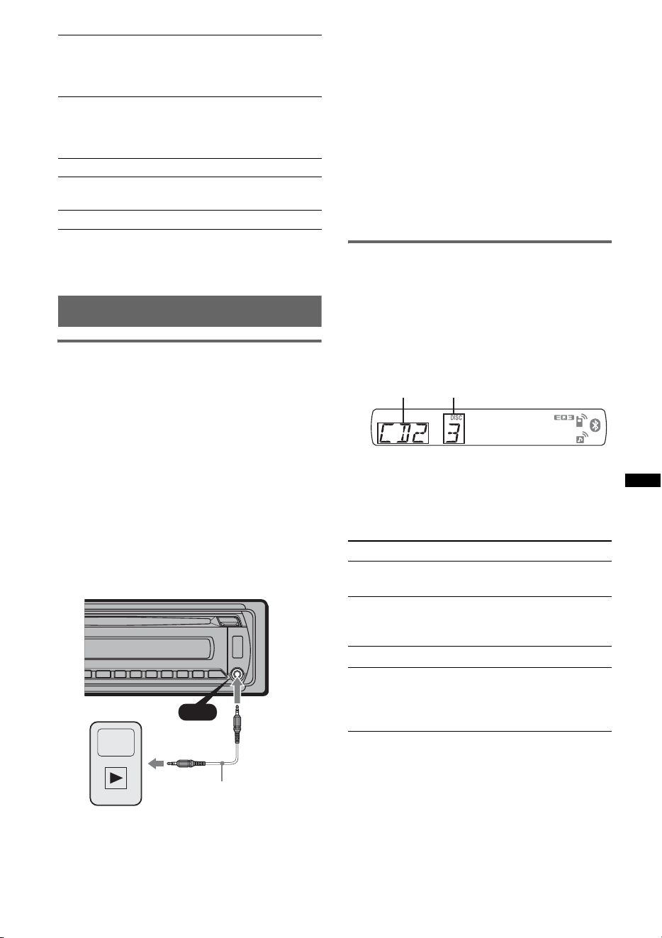
23
Uso de un equipo opcional
Equipo auxiliar de audio
Si conecta un dispositivo de audio portátil
opcional a la toma de entrada AUX (minitoma
estéreo) de la unidad y simplemente selecciona la
fuente, podrá escuchar por los altavoces del
automóvil. Puede ajustar cualquier diferencia en
el nivel de volumen entre la unidad y el
dispositivo de audio portátil. Siga el
procedimiento explicado a continuación:
Conexión del dispositivo de audio
portátil
1 Apague el dispositivo de audio portátil.
2 Baje el volumen de la unidad.
3 Conecte a la unidad.
* Asegúrese de utilizar una clavija recta.
Ajuste del nivel de volumen
Asegúrese de ajustar el volumen de cada equipo
de audio conectado antes de la reproducción.
1 Baje el volumen de la unidad.
2 Presione (SOURCE) varias veces hasta que
aparezca “AUX”.
Aparecerá “AUX FRONT IN”.
3 Inicie la reproducción en el dispositivo de
audio portátil con un volumen moderado.
4 Seleccione el volumen habitual en la unidad.
5 Ajuste el nivel de volumen (página 21).
Cambiador de CD
Selección del cambiador
1 Presione (SOURCE) varias veces hasta que
aparezca “CD”.
2 Presione (MODE) varias veces hasta que
aparezca el cambiador deseado.
Se inicia la reproducción.
Omisión de álbumes y discos
1 Durante la reproducción, presione (1)/(2)
(ALBM –/+).
HPF (Filtro de paso alto)
Permite seleccionar la frecuencia de corte de los
altavoces frontal/posterior: “OFF”, “80Hz”,
“100Hz”, “120Hz”, “140Hz”, “160Hz”.
LOUD (Sonoridad)
Permite reforzar los bajos y agudos para obtener
un sonido nítido a niveles bajos de volumen:
“ON”, “OFF”.
BTM (página 12)
DM+*
2
Para ajustar la función DM+: “ON”, “OFF”.
BT INIT*
1
(página 21)
*1 Cuando la unidad está apagada.
*2 Cuando se activa la fuente CD/USB.
*3 Cuando se recibe FM.
AUX
AUX
Cable de conexión*
(no suministrado)
Para omitir Presione (1)/(2) (ALBM –/+)
un álbum y suéltelo (manténgalo
presionado un momento).
álbumes de
forma continua
antes de que transcurran
2 segundos de la primera vez
que lo soltó.
discos varias veces.
discos de forma
continua
y, a continuación, pulse de
nuevo antes de que transcurran
2 segundos y mantenga
presionado.
continúa en la página siguiente t
Número de
unidad
Número de
disco
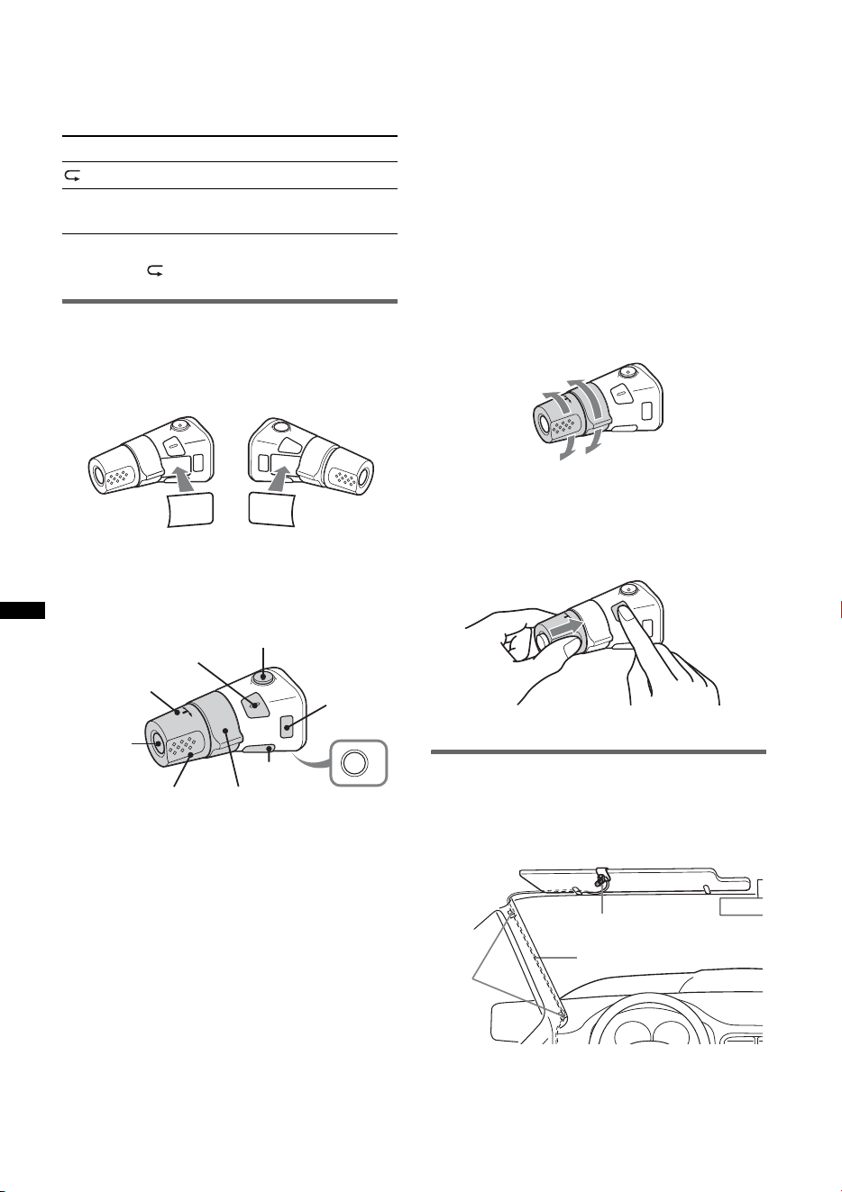
24
Reproducción repetida y aleatoria
1 Durante la reproducción, presione (3) (REP)
o (4) (SHUF) varias veces hasta que aparezca
el ajuste deseado.
Para volver al modo de reproducción normal,
seleccione “ OFF” o “SHUF OFF”.
Mando rotatorio RM-X4S
Colocación de la etiqueta
Coloque la etiqueta de indicación según el modo
en que instale el mando rotatorio.
Ubicación de los controles
Los botones correspondientes en el mando
rotatorio controlan las mismas funciones que los
de esta unidad.
La operación de los controles siguientes del
mando rotatorio es distinta que en la unidad.
• Botón ATT (atenuación)
Para atenuar el sonido. Para cancelar esta
función, vuelva a presionarlo.
• Botón SEL (selección)
Funciona igual que el botón de selección de la
unidad.
• Control PRESET/DISC
CD/USB: funciona de igual manera que
(1)/(2) (ALBM –/+) en la unidad (presionar y
girar).
Radio: para recibir las emisoras almacenadas
(presionar y girar).
• Control VOL (volumen)
Funciona de igual manera que el selector de
control en la unidad (girar).
• Control SEEK/AMS
Funciona de igual manera que (SEEK) +/– en
la unidad (girar o girar y mantener).
• Botón DSPL (pantalla)
Para cambiar los elementos en pantalla.
• Botón MODE
Presionar para: seleccionar la banda de radio
(FM/AM) o seleccionar el modo de
reproducción del iPod.
Mantener presionado para: acceder al control
de pasajero o cancelar dicha función.
Cambio del sentido de
funcionamiento
El sentido de funcionamiento de los controles
está ajustado de fábrica como se muestra a
continuación.
Si necesita instalar el mando rotatorio en el lado
derecho de la columna de la dirección, puede
invertir el sentido de funcionamiento.
1 Mientras presiona el control VOL, mantenga
presionado ( SEL ).
Micrófono externo XA-MC10
Al conectar un micrófono externo opcional al
conector de entrada de micrófono, puede mejorar
la calidad de audio al hablar a través de esta
unidad.
Sugerencia
Es posible establecer la prioridad de los micrófonos
(página 22).
Seleccione Para reproducir
DISC discos en forma repetida.
SHUF
CHANGER
pistas del cambiador en orden
aleatorio.
S
EL
D
SP
L
M
O
D
E
S
E
L
D
S
P
L
M
O
D
E
OFF
ATT
SEL
SOURCE
DSPL
MODE
OFF
VOL
SEEK/AMS
PRESET/
DISC
Para aumentar
Para disminuir
Micrófono externo
Cable de conexión
Abra-
zade-
ras
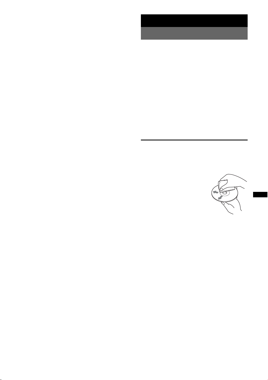
25
Nota
Conecte XA-MC10 como micrófono externo. Si
conecta otro dispositivo, es posible que se produzcan
fallas de funcionamiento o que no pueda realizar
llamadas.
Información complementaria
Precauciones
• Permita que la unidad se enfríe antes de utilizarla
si el automóvil ha estado estacionado bajo la luz
solar directa.
• La antena motorizada se extiende
automáticamente.
Condensación de humedad
Si se produce condensación de humedad en el
interior de la unidad, extraiga el disco y espere una
hora aproximadamente hasta que se evapore; de lo
contrario, la unidad no funcionará correctamente.
Para mantener una alta calidad de
sonido
No derrame líquidos sobre la unidad ni sobre los
discos.
Notas sobre los discos
• No exponga los discos a la luz solar directa o a
fuentes de calor como, por ejemplo, conductos de
aire caliente, ni los deje en un automóvil
estacionado bajo la luz solar directa.
• Antes de reproducir los discos,
límpielos con un paño de
limpieza desde el centro hacia
los bordes. No utilice
disolventes como bencina,
diluyentes o productos de
limpieza disponibles en el
mercado.
• Esta unidad se diseñó para
reproducir discos que cumplen con el estándar
Compact Disc (CD). Los discos DualDisc y
algunos discos de música codificados con
tecnologías de protección de los derechos de autor
no cumplen con el estándar Compact Disc (CD) y,
por lo tanto, es posible que no puedan
reproducirse en esta unidad.
• Discos que esta unidad NO puede
reproducir
– Discos con etiquetas, adhesivos, cinta adhesiva o
papel pegado. Si lo hace, puede causar una falla
de funcionamiento o hacer que el disco quede
inutilizable.
– Discos con formas no estándar (por ejemplo,
formas de corazón, cuadrado o estrella). Si lo
intenta, puede dañar la unidad.
– Discos de 8 cm
continúa en la página siguiente t
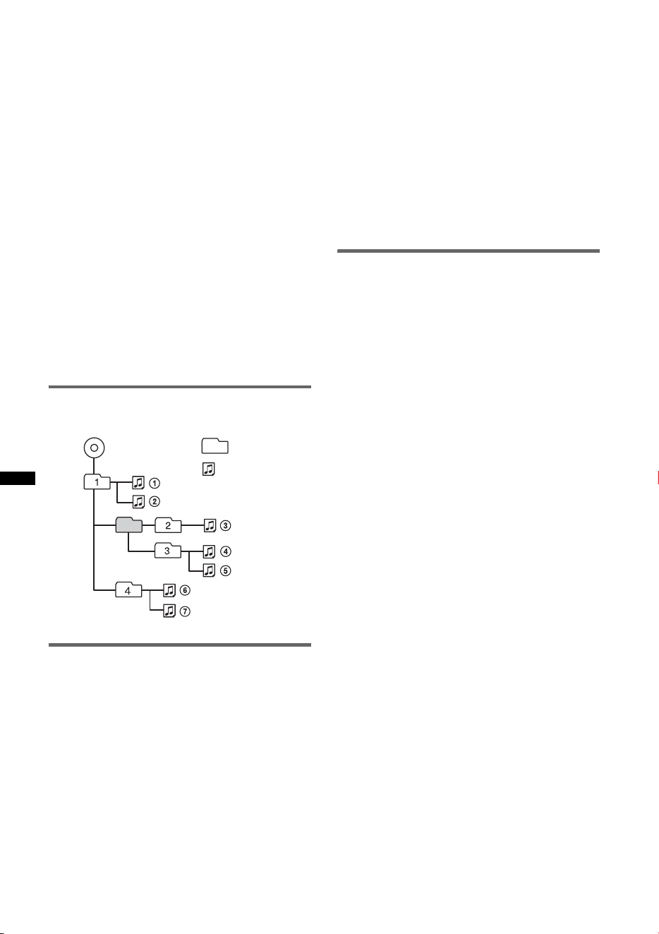
26
Notas sobre los discos CD-R/CD-RW
• El número máximo de: (solamente CD-R/
CD-RW)
– carpetas (álbumes): 150 (incluida la carpeta raíz)
– archivos (pistas) y carpetas: 300 (si un nombre
de carpeta o archivo contiene muchos caracteres,
es posible que este número sea inferior a 300)
– caracteres que se pueden visualizar en el nombre
de una carpeta o archivo: 32 (Joliet) o
64 (Romeo)
• Si el disco multisesión empieza con una sesión
CD-DA, se reconoce como un disco CD-DA y las
demás sesiones no se reproducirán.
• Discos que esta unidad NO puede
reproducir
– CD-R/CD-RW con calidad de grabación
deficiente.
– CD-R/CD-RW grabados con un dispositivo de
grabación no compatible.
– CD-R/CD-RW que hayan sido finalizados
incorrectamente.
– CD-R/CD-RW distintos de los grabados en
formato CD de música o formato MP3 que
cumpla los estándares ISO9660 nivel 1/nivel 2,
Joliet/Romeo o multisesión.
Orden de reproducción de archivos
MP3/WMA/AAC
Acerca de iPod
• Es posible establecer una conexión con los
siguientes modelos de iPod. Actualice sus iPod al
software más reciente antes de utilizarlo.
– iPod touch
– iPod classic
– iPod con video*
– iPod nano (tercera generación)
– iPod nano (segunda generación)
– iPod nano (primera generación)*
– iPhone y iPhone 3G
* La función de control del control del pasajero no se
encuentra disponible en el iPod nano (primera
generación) ni en el iPod con video.
• “Made for iPod” indica que un accesorio
electrónico se diseñó para conectarse
específicamente a dispositivos iPod y que el
fabricante obtuvo la certificación necesaria para
que cumpla con los estándares de rendimiento de
Apple.
• “Works with iPhone” indica que un accesorio
electrónico se diseñó para conectarse
específicamente a dispositivos iPhone y que el
fabricante obtuvo la certificación necesaria para
que cumpla con los estándares de rendimiento de
Apple.
• Apple no se hace responsable del funcionamiento
de este dispositivo en cumplimiento de los
estándares de seguridad y normativa.
Acerca de la función Bluetooth
¿Qué es la tecnología Bluetooth?
• La tecnología inalámbrica Bluetooth es una
tecnología inalámbrica de corto alcance que
permite la comunicación de datos inalámbrica
entre dispositivos digitales como, por ejemplo, un
teléfono celular y unos auriculares. La tecnología
inalámbrica Bluetooth tiene una cobertura de unos
10 m. La conexión de dos dispositivos es la más
habitual, pero algunos dispositivos pueden
conectarse a varios dispositivos al mismo tiempo.
• No es necesario utilizar un cable para realizar la
conexión, ya que la tecnología Bluetooth es
inalámbrica. Tampoco es necesario que los
dispositivos estén orientados entre sí, como sucede
con la tecnología de infrarrojos. Por ejemplo,
puede utilizar este tipo de dispositivos dentro de
una bolsa o un bolsillo.
• La tecnología Bluetooth es un estándar
internacional admitido por millones de empresas
en todo el mundo y que utilizan varias compañías
a escala internacional.
Acerca de la comunicación Bluetooth
• La tecnología inalámbrica Bluetooth tiene una
cobertura de unos 10 m.
El área de cobertura puede variar en función de los
obstáculos (personas, objetos metálicos, paredes,
etc.) o del entorno electromagnético.
• Las condiciones siguientes pueden afectar la
sensibilidad de la comunicación Bluetooth.
– La existencia de obstáculos como, por ejemplo,
una persona, un objeto metálico o una pared
entre esta unidad y el dispositivo Bluetooth.
– El uso de dispositivos que utilicen una
frecuencia de 2,4 GHz como, por ejemplo, un
dispositivo LAN inalámbrico o un microondas
cerca de la unidad.
Carpeta
(álbum)
Archivo MP3/
WMA/AAC
(pista)
MP3/WMA/AAC
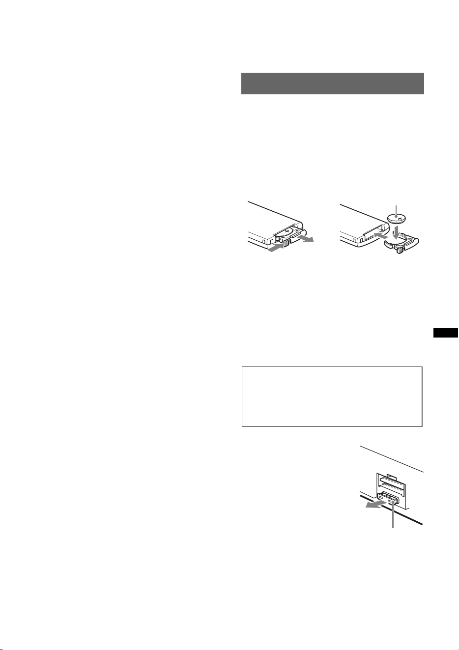
27
• Como los dispositivos Bluetooth y las LAN
inalámbricas (IEEE802.11b/g) utilizan la misma
frecuencia, pueden producirse interferencias de
microondas que provoquen el deterioro de la
velocidad de comunicación, la aparición de ruido
o una conexión no válida si la unidad se utiliza
cerca de un dispositivo LAN inalámbrico. En este
caso, realice el procedimiento siguiente.
– Utilice esta unidad a una distancia mínima de
10 m del dispositivo LAN inalámbrico.
– Si utiliza esta unidad a menos de 10 m de un
dispositivo LAN inalámbrico, apague el
dispositivo LAN inalámbrico.
– Instale esta unidad y el dispositivo Bluetooth a la
distancia más corta posible entre sí.
• Las microondas que emite un dispositivo
Bluetooth pueden afectar al funcionamiento de
dispositivos médicos electrónicos. Apague esta
unidad y los demás dispositivos Bluetooth en los
lugares siguientes, ya que podrían provocar un
accidente.
– donde exista gas inflamable, en un hospital, tren,
avión o gasolinera
– cerca de puertas automáticas o alarmas de
incendio
• Esta unidad admite capacidades de seguridad que
cumplen con el estándar Bluetooth para
proporcionar una conexión segura al utilizar la
tecnología inalámbrica Bluetooth, pero es posible
que la seguridad sea insuficiente según el ajuste.
Tenga cuidado al realizar una comunicación con la
tecnología inalámbrica Bluetooth.
• No se aceptan responsabilidades por la pérdida de
información que pudiera producirse durante una
comunicación Bluetooth.
• No se garantiza la comunicación con todos los
dispositivos Bluetooth.
– Un dispositivo que disponga de la función
Bluetooth debe cumplir el estándar Bluetooth
SIG y estar autenticado.
– Incluso en el caso de que el dispositivo
conectado cumpla el estándar Bluetooth
mencionado anteriormente, es posible que
algunos dispositivos no puedan conectarse o
funcionar correctamente, según las
características o las especificaciones del
dispositivo.
– Mientras esté hablando con el manos libres del
teléfono, puede producirse ruido, según el
dispositivo o el entorno de comunicación.
• En función del dispositivo que vaya a conectarse,
es posible que transcurra cierto tiempo antes de
que se inicie la comunicación.
Otros
• Es posible que el dispositivo Bluetooth no
funcione en teléfonos celulares, dependiendo de
las condiciones de las ondas de radio y la
ubicación en la que se utilice el equipo.
• Si no se siente cómodo después de utilizar el
dispositivo Bluetooth, deje de utilizarlo
inmediatamente. Si el problema persiste, consulte
con el distribuidor Sony más cercano.
Si desea realizar alguna consulta o solucionar algún
problema relativo a la unidad que no se trate en este
manual, póngase en contacto con el distribuidor
Sony más cercano.
Mantenimiento
Sustitución de la pila de litio del
control remoto de tarjeta
En condiciones normales, la pila dura
aproximadamente 1 año. (La duración puede ser
menor en función de las condiciones de uso.)
El alcance del control remoto de tarjeta disminuye a
medida que se agota la pila. Sustitúyala por una pila
de litio CR2025 nueva. El uso de cualquier otra pila
podría provocar un incendio o una explosión.
Notas sobre la pila de litio
• Mantenga la pila de litio fuera del alcance de los
niños. Si se ingiriese, póngase en contacto
inmediatamente con un médico.
• Limpie la pila con un paño seco para garantizar un
contacto óptimo.
• Asegúrese de observar la polaridad correcta al
instalarla.
• No sujete la pila con pinzas metálicas, ya que podría
producirse un cortocircuito.
Sustitución del fusible
Al sustituir el fusible, asegúrese
de utilizar uno cuyo amperaje
coincida con el especificado en
el original. Si el fusible se
funde, verifique la conexión de
alimentación y sustitúyalo. Si el
fusible vuelve a fundirse
después de sustituirlo, es
posible que exista alguna falla
de funcionamiento interno. En
tal caso, consulte con el
distribuidor Sony más cercano.
continúa en la página siguiente t
1
2
Lado + hacia arriba
c
ADVERTENCIA
La pila puede explotar si no se emplea
adecuadamente.
No recargue la pila; tampoco la desmonte ni
la arroje al fuego.
Fusible (10 A)
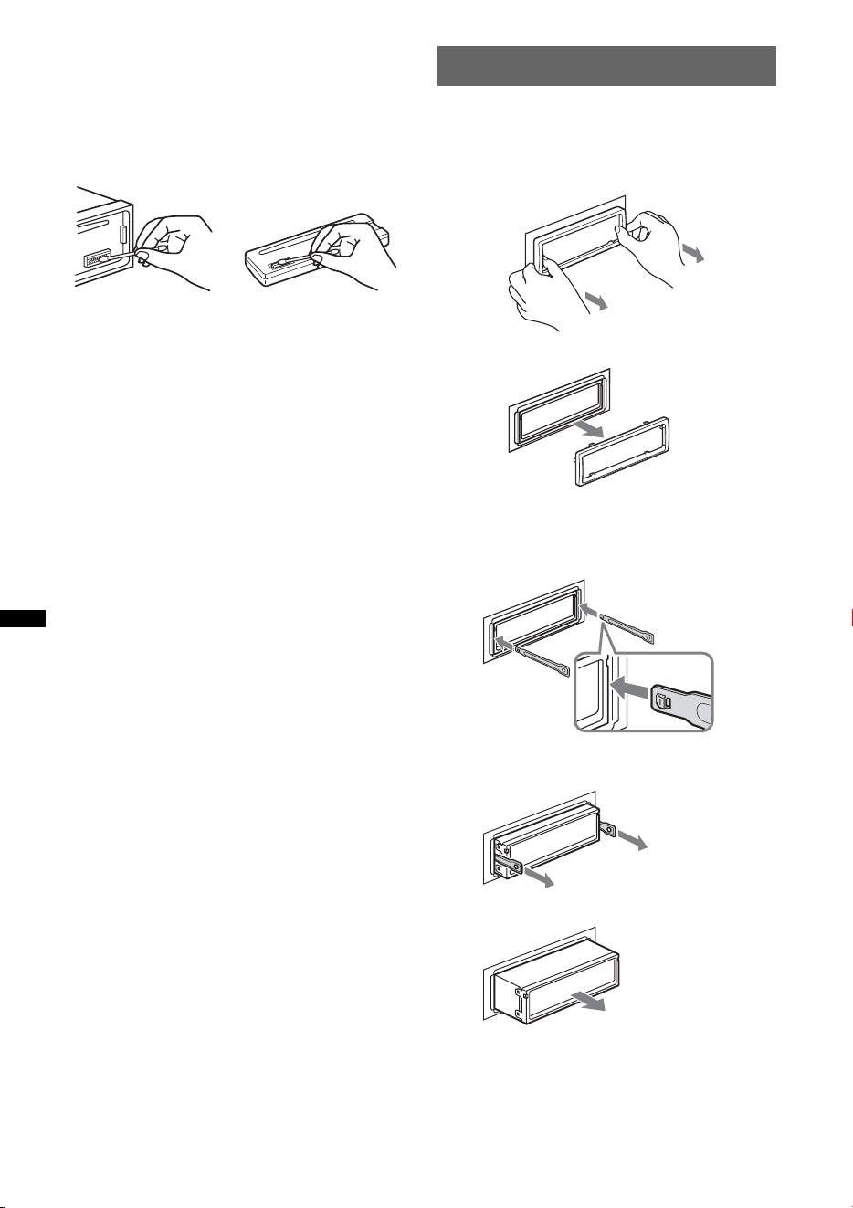
28
Limpieza de los conectores
Es posible que la unidad no funcione correctamente
si los conectores entre ésta y el panel frontal están
sucios. Para evitar esta situación, extraiga el panel
frontal (página 7) y limpie los conectores con un
hisopo de algodón. No aplique demasiada fuerza, ya
que podría dañar los conectores.
Notas
• Por razones de seguridad, apague el motor antes de
limpiar los conectores y extraiga la llave del
interruptor de encendido.
• No toque nunca los conectores directamente con los
dedos ni con ningún dispositivo metálico.
Extracción de la unidad
1 Extraiga el marco de protección.
1Extraiga el panel frontal (página 7).
2Apriete ambos lados del marco de
protección y extráigalo.
2 Extraiga la unidad.
1Inserte las dos llaves de liberación
simultáneamente hasta escuchar un clic.
2Tire de las llaves de liberación para extraer
la unidad.
3Deslice la unidad para extraerla del marco.
Unidad principal
Parte posterior
del panel frontal
x
El gancho
debe mirar
hacia adentro.

29
Especificaciones
Sección del reproductor de CD
Relación señal-ruido: 120 dB
Respuesta de frecuencia: de 10 a 20 000 Hz
Fluctuación y trémolo: inferior al límite medible
Sección del sintonizador
FM
Rango de sintonización: de 87,5 a 107,9 MHz
Terminal de antena:
conector de antena externa
Frecuencia intermedia: 150 kHz
Sensibilidad útil: 10 dBf
Selectividad: 75 dB a 400 kHz
Relación señal-ruido: 70 dB (mono)
Separación: 40 dB a 1 kHz
Respuesta de frecuencia: de 20 a 15 000 Hz
AM
Rango de sintonización: de 530 a 1 710 kHz
Terminal de antena:
conector de antena externa
Frecuencia intermedia: 25 kHz
Sensibilidad: 26 µV
Sección del reproductor USB
Interfaz: USB (velocidad máxima)
Corriente máxima: 500 mA
Comunicación inalámbrica
Sistema de comunicación:
Versión estándar Bluetooth 2.0
Salida:
Energía estándar Bluetooth Clase 2 (Máx. +4 dBm)
Alcance máximo de la comunicación:
Línea de visión aprox. 10 m*
1
Banda de frecuencias:
Banda de 2,4 GHz (2,4000 a 2,4835 GHz)
Método de modulación: FHSS
Perfiles compatibles de Bluetooth*
2
:
A2DP (Advanced Audio Distribution Profile)
AVRCP (Audio Video Remote Control Profile)
HFP (Handsfree Profile) 1.5
HSP (Headset Profile)
*1 El alcance real variará en función de factores como
los obstáculos entre los dispositivos, los campos
magnéticos alrededor de un horno de microondas,
electricidad estática, sensibilidad de recepción,
funcionamiento de la antena, sistema operativo,
aplicación del software, etc.
*2 Los perfiles estándar de Bluetooth indican el
propósito de la comunicación Bluetooth entre
dispositivos.
Sección del amplificador de potencia
Salida: salidas de altavoz (conectores de sellado
seguro)
Impedancia de altavoces: de 4 a 8 Ω
Salida máxima de potencia: 52 W × 4 (a 4 Ω)
Generales
Salidas:
Terminal de salidas de audio (frontal/posterior)
Terminal de salida del altavoz potenciador de
graves (mono)
Terminal de control del relé de la antena
motorizada
Terminal de control del amplificador de potencia
Entradas:
Terminal de entrada del control remoto
Terminal de entrada de la antena
Terminal de control ATT de teléfono
Terminal de entrada de control BUS
Terminal de entrada de audio BUS
Toma de entrada AUX (minitoma estéreo)
Terminal de entrada de señal USB
Controles de tono:
Bajos: ±10 dB a 60 Hz (XPLOD)
Medios: ±10 dB a 1 kHz (XPLOD)
Altos: ±10 dB a 10 kHz (XPLOD)
Requisitos de alimentación: batería de automóvil de
cc de 12 V (masa negativa)
Dimensiones: aprox. 178 × 50 × 179 mm (an/al/prf)
Dimensiones de montaje: aprox. 182 × 53 × 162 mm
(an/al/prf)
Peso: aprox. 1,2 kg
Accesorios suministrados:
Control remoto de tarjeta: RM-X304
Componentes de instalación y conexiones
(1 juego)
Equipo y accesorios opcionales:
Mando rotatorio: RM-X4S
Cable BUS (suministrado con un cable con
terminales RCA): RC-61 (1 m), RC-62 (2 m)
Cambiador de CD (10 discos): CDX-757MX
Cambiador de CD (6 discos): CDX-T69
Selector de fuente: XA-C40
Selector AUX-IN: XA-300
Cable de conexión USB para iPod: RC-100IP
Sintonizador HD Radio
TM
: XT-100HD
Micrófono externo: XA-MC10
Es posible que su distribuidor no comercialice
algunos de los accesorios que figuran en la lista
anterior. Pídale información detallada.
El diseño y las especificaciones están sujetos a
cambios sin previo aviso.
• Ciertas placas del circuito impreso no contienen
retardantes de llama halogenados.
• Los chasis impresos no contienen retardantes de
llama halogenados.
• Para el material de relleno y protección se ha
utilizado papel.
30
Solución de problemas
La siguiente lista de comprobación le ayudará a
solucionar los problemas que puedan producirse con
la unidad.
Antes de consultarla, revise los procedimientos de
conexión y de funcionamiento.
Si el problema persiste, visite el siguiente sitio web
de asistencia al cliente.
Generales
La unidad no recibe alimentación.
• Compruebe la conexión o el fusible.
• Si la unidad está apagada y la pantalla desaparece, no
se puede operar con el control remoto.
tEncienda la unidad.
La antena motorizada no se extiende.
La antena motorizada no dispone de una caja de relé.
No se emite el sonido.
• La función ATT está activada o la función ATT de
teléfono (cuando se conecta el cable de interfaz de un
teléfono para automóvil al cable ATT) está activada.
• La posición del control de equilibrio “FAD” no está
ajustada para un sistema de 2 altavoces.
• El dispositivo de audio Bluetooth se encuentra en
pausa.
tCancele la pausa.
No se escuchan pitidos.
• El sonido de los pitidos está cancelado (página 22).
• Se encuentra conectado un amplificador de potencia
opcional y no está usando el amplificador integrado.
El contenido de la memoria se borró.
• Presionó el botón RESET.
tVuelva a almacenar los datos en la memoria.
• Se desconectó el cable de la alimentación o la batería
o no está conectado correctamente.
Las emisoras almacenadas y la hora correcta
se borraron.
El fusible se fundió.
Se escucha ruido cuando se cambia la
posición de la llave de encendido.
Los cables no se conectaron en forma correcta al
conector de alimentación auxiliar del automóvil.
Durante la reproducción o la recepción, se
inicia el modo de demostración.
Si no se realiza ninguna operación durante 5 minutos y
“DEMO-ON” está ajustada, se inicia el modo de
demostración.
t Ajuste “DEMO-OFF” (página 22).
Sitio Web de soporte técnico en línea
http://esupport.sony.com
http://www.xplodsony.com/
Las indicaciones desaparecen de la pantalla o
no aparecen en ella.
• El atenuador está ajustado en “DIM-ON”
(página 22).
• La pantalla se apaga si mantiene presionado (OFF).
t Mantenga presionado (OFF) en la unidad hasta
que se ilumine la pantalla.
• Los conectores están sucios (página 28).
La función de desconexión automática no
funciona.
La unidad está encendida. La función de desconexión
automática se activa después de apagar la unidad.
t Apague la unidad.
Reproducción de CD
No es posible insertar el disco.
• Ya hay un disco insertado.
• El disco se insertó a la fuerza al revés o de forma
incorrecta.
No se inicia la reproducción del disco.
• El disco está sucio o es defectuoso.
• Los discos CD-R/CD-RW no son para audio
(página 26).
No es posible reproducir archivos MP3/WMA/
AAC.
El disco no es compatible con el formato y la versión
de MP3/WMA/AAC. Para obtener información acerca
de los discos y formatos que se pueden reproducir,
visite el sitio web de soporte técnico de Sony.
Los archivos MP3/WMA/AAC tardan más
tiempo en reproducirse que los demás.
El inicio de la reproducción de los siguientes discos
tarda algo más de tiempo.
– disco grabado con una estructura de árbol
complicada.
– disco grabado en Multi Session.
– disco al que es posible añadir datos.
Los elementos de pantalla no se desplazan.
• En el caso de discos con muchos caracteres, es
posible que éstos no se desplacen.
• “A.SCRL” está ajustado en “OFF”.
t Ajuste “A.SCRL-ON” (página 22).
t Mantenga presionado (DSPL) (SCRL).
Se producen saltos de sonido.
• La instalación no es correcta.
t Instale la unidad en un ángulo inferior a 45° en
una parte firme del automóvil.
• El disco está sucio o es defectuoso.
Los botones de operación no funcionan.
El disco no se expulsa.
Presione el botón RESET (página 6).
31
Recepción de radio
No es posible recibir las emisoras.
Hay ruidos que obstaculizan el sonido.
La conexión es incorrecta.
tConecte un cable de control de antena motorizada
(azul) o un cable de fuente de alimentación auxiliar
(rojo) al cable de suministro de alimentación del
amplificador de antena del automóvil (solo cuando
el automóvil tenga una antena de FM/AM
incorporada en el cristal posterior o lateral).
tCompruebe la conexión de la antena del automóvil.
tSi la antena automática no se extiende, compruebe
la conexión del cable de control de la antena
motorizada.
No es posible utilizar la sintonización
programada.
• Almacene la frecuencia correcta en la memoria.
• La señal de emisión es demasiado débil.
No es posible utilizar la sintonización
automática.
• El ajuste del modo de búsqueda local no es correcto.
t La sintonización se detiene con demasiada
frecuencia:
Ajuste “LOCAL-ON” (página 22).
t La sintonización no se detiene en una emisora:
Ajuste “LOCAL-OFF” (página 22).
• La señal de emisión es demasiado débil.
t Use la sintonización manual.
Durante la recepción de FM, la indicación “ST”
parpadea.
• Sintonice la frecuencia con precisión.
• La señal de emisión es demasiado débil.
t Ajuste “MONO-ON” (página 22).
Un programa de FM emitido en estéreo se
escucha en monoaural.
La unidad se encuentra en el modo de recepción
monoaural.
tAjuste “MONO-OFF” (página 22).
Reproducción USB
No es posible reproducir elementos a través de
un concentrador USB.
Esta unidad no puede reconocer dispositivos USB a
través de un concentrador USB.
No se pueden reproducir elementos.
El dispositivo USB no funciona.
tVuelva a conectarlo.
El dispositivo USB tarda más tiempo en iniciar
la reproducción.
El dispositivo USB contiene archivos con una
estructura de árbol complicada.
Suena un pitido.
El dispositivo USB se ha desconectado durante la
reproducción.
tAntes de desconectar un dispositivo USB,
asegúrese de que se ha detenido la reproducción
para proteger los datos.
El sonido es discontinuo.
Es posible que la discontinuidad del sonido se deba a
una alta velocidad de bits de más de 320 kbps.
Función Bluetooth
El dispositivo de conexión no puede detectar
esta unidad.
• Antes de finalizar el emparejamiento, ajuste la unidad
en el modo de espera de emparejamiento.
• Mientras se conecta a un dispositivo Bluetooth, esta
unidad no puede detectarse desde otro dispositivo.
Desconecte la conexión actual y busque esta unidad
desde otro dispositivo.
• Después de realizar el emparejamiento del
dispositivo, active la salida de la señal Bluetooth
(página 18).
No es posible realizar la conexión.
• Conexión a esta unidad desde un dispositivo
Bluetooth o viceversa. La conexión se controla desde
un extremo (esta unidad o el dispositivo Bluetooth),
pero no desde ambos.
• Compruebe el proceso de emparejamiento y
conexión en el manual del otro dispositivo, etc. y
repítalo.
El volumen de la voz de la persona que habla
es bajo.
Ajuste el nivel de volumen.
El interlocutor de una llamada le notifica que el
volumen es demasiado bajo o demasiado alto.
Ajuste el volumen según corresponda mediante el
ajuste de ganancia del micrófono (página 19).
Se producen ecos o ruidos durante las
conversaciones telefónicas.
• Baje el volumen.
• Si el ruido del ambiente es alto, sin tomar en cuenta
el sonido de la llamada, intente reducir dicho ruido.
Ej.: Si hay una ventanilla abierta y el ruido de la
calle, etc., es alto, cierre la ventanilla. Si el aire
acondicionado está alto, baje el aire acondicionado.
El teléfono no está conectado.
Durante la reproducción en el dispositivo de audio
Bluetooth, el teléfono no se conecta aunque presione
(manos libres).
t Realice la conexión desde el teléfono.
La calidad de sonido del teléfono es baja.
La calidad del sonido del teléfono depende de las
condiciones de recepción del teléfono celular.
t Mueva su automóvil a un lugar en el que pueda
mejorar la señal del teléfono celular si la recepción
es de mala calidad.
El volumen del dispositivo de audio conectado
es bajo (alto).
El nivel de volumen cambiará dependiendo del
dispositivo de audio.
t Ajuste el volumen del dispositivo de audio
conectado o de esta unidad.
continúa en la página siguiente t
32
Mensajes/indicaciones de error
Se omite el sonido durante la reproducción de
un dispositivo de audio Bluetooth.
• Reduzca la distancia entre la unidad y el dispositivo
de audio Bluetooth.
• Si el dispositivo de audio Bluetooth está guardado en
una caja que interrumpe la señal, retire la caja del
dispositivo de audio para utilizarlo.
• En los alrededores se utilizan varios dispositivos
Bluetooth u otros dispositivos que emiten ondas de
radio.
tApague los otros dispositivos.
tReduzca la distancia que lo separa de los otros
dispositivos.
• El sonido de reproducción se detiene
momentáneamente mientras se establece la conexión
entre esta unidad y el teléfono celular. No se trata de
una falla de funcionamiento.
No es posible controlar el dispositivo de audio
Bluetooth conectado.
Compruebe que el dispositivo de audio Bluetooth
conectado sea compatible con AVRCP.
Algunas funciones no funcionan.
Compruebe que el dispositivo de conexión sea
compatible con las funciones en cuestión.
Se contesta una llamada accidentalmente.
El teléfono conectado está configurado para contestar
las llamadas automáticamente.
Durante la llamada con manos libres, los
altavoces del automóvil no emiten ningún
sonido.
Si el sonido de salida viene del teléfono celular, ajuste
el teléfono para que el sonido se emita por los
altavoces del automóvil.
“OFF BT” aparece durante la inicialización.
Mantenga presionado (BT) hasta que se apague “ ”.
A continuación, vuelva a efectuar la inicialización
(página 21).
El micrófono externo no funciona.
El ajuste del micrófono no es el adecuado.
t Ajuste “MIC-EXT” (página 22).
CHECKING
La unidad está confirmando la conexión de un
dispositivo USB.
t Espere a que aparezca la confirmación de que la
conexión ha finalizado.
ERROR*
1
• El disco está sucio o se insertó al revés.*
2
t Límpielo o insértelo de forma correcta.
• Se insertó un disco vacío.
• No es posible reproducir el disco debido a un
problema.
t Inserte otro disco.
• El dispositivo USB no ha sido reconocido
automáticamente.
t Conéctelo nuevamente.
• Presione Z para extraer el disco.
FAILURE (permanece encendido hasta que se presiona
cualquier botón.)
La conexión de los altavoces y amplificadores es
incorrecta.
t Consulte el manual de instalación de este modelo
para revisar la conexión.
FAILURE (permanece encendido durante
aproximadamente un segundo.)
Con el sintonizador SAT conectado, se ha producido
un error al intentar almacenar un canal de radio SAT
como preajustado.
t Compruebe que recibe el canal que desea
almacenar e inténtelo de nuevo.
HUB NO SUPRT
El concentrador USB no es compatible con esta
unidad.
LOAD
El cambiador de CD no carga el disco.
t Espere hasta que finalice la carga.
L. SEEK +/–
El modo de búsqueda local está activado durante la
sintonización automática.
NO DEV (No hay dispositivo)
(SOURCE) se selecciona sin que esté conectado un
dispositivo USB. Se ha desconectado un dispositivo
USB o un cable USB durante la reproducción.
t Asegúrese de conectar un dispositivo USB y un
cable USB.
NO DISC
El disco no se encuentra insertado en el cambiador de
CD.
t Inserte discos en el cambiador de CD.
NO MAG
El cargador de discos no se encuentra insertado en el
cambiador de CD.
t Inserte el cargador de discos en el cambiador de
CD.
33
Si estas soluciones no ayudan a mejorar la situación,
póngase en contacto con el distribuidor Sony más
cercano.
Si entrega la unidad para su reparación a causa de
problemas en la reproducción de CD, lleve el disco
que se utilizó cuando se produjo el problema.
NO MUSIC
El disco o dispositivo USB no contiene ningún archivo
de música.
tInserte un CD de música en la unidad o un
cambiador de CD con archivos MP3 compatible.
tConecte un dispositivo USB que contenga algún
archivo de música.
NO NAME
No se grabó un nombre de pista, álbum, artista o disco
en la pista.
OFFSET
Es posible que se haya producido una falla interna.
tRevise la conexión. Si el indicador de error
permanece en pantalla, póngase en contacto con el
distribuidor Sony más cercano.
OVERLOAD
El dispositivo USB está sobrecargado.
tDesconecte el dispositivo USB y, a continuación,
presione (SOURCE) para cambiar la fuente.
tIndica que el dispositivo USB está fuera de
servicio, o que existe un dispositivo incompatible
conectado.
READ
La unidad está leyendo toda la información de pistas y
de álbumes del disco.
tEspere hasta que finalice la lectura y se inicie la
reproducción automáticamente. Es posible que
demore más de un minuto en función de la
estructura del disco.
RESET
No es posible utilizar la unidad de CD, el cambiador de
CD o el dispositivo USB debido a un problema.
tPresione el botón RESET (página 6).
USB NO SUPRT (USB no compatible)
El dispositivo USB conectado no es compatible.
tPara obtener más información acerca de la
compatibilidad del dispositivo USB, visite el sitio
web de soporte técnico de Sony.
“” o “”
Durante la operación de avance o retroceso rápido,
llegó al principio o al final del disco, por lo que no es
posible continuar.
“”
No se puede mostrar el carácter con la unidad.
*1 Si se produce un error durante la reproducción de
un CD, el número de disco del CD no aparece en
pantalla.
*2 La pantalla muestra el número del disco que causa
el error.
Sony Corporation
Printed in Thailand
http://www.sony.net/
If you have any questions/problems
regarding this product, try the following:
1
Read Troubleshooting in these
Operating Instructions.
2
Reset the unit.
Note: Stored data may be erased.
3
Please contact (U.S.A. only);
Call
1-800-222-7669
URL
http://www.SONY.com