Loading ...
Loading ...
Loading ...
10 | JL Audio - M400/4 Owner’s Manual
11
STATUS LED / PROTECTION CIRCUITRY
There is a single multi-color LED on the top
surface of the amplifier to indicate the amplifier’s
operating status.
1 ) F l a s h i n g G r e e n : amplifier is powering up,
audio output is muted.
2) Constant Green: amplifier is on and
functioning normally, audio output is active.
3) Constant Red: Indicates that the
amplifier has exceeded its safe operating
temperature, putting the amplifier into a
self-protection mode, which reduces the
peak power output of the amplifier. When its
temperature returns to a safe level, the red
light will return to green and the amplifier will
return to full-power operating mode.
4) Constant Amber (yellow): Indicates
that an over-current condition has occurred
and is accompanied by a muting of the affected
channel(s). Because the muting behavior may be
very short in duration, it may manifest itself as
an audible, repetitive ticking noise in the output.
Over-current conditions can be caused by a
speaker impedance lower than the optimum load
impedance range for the amplifier or a short-
circuit in the speaker wiring. The latter can result
from a short circuit between the positive and
negative speaker wires or between either speaker
wire and a power wire. The “Status LED” will
remain amber for a few seconds, even if the over-
current condition is of a very short duration.
This functionality can be used to diagnose a
short-circuit by only connecting one channel at
a time. The “Status LED” will turn amber when
you connect the channel that is experiencing the
problem and turn the volume up.
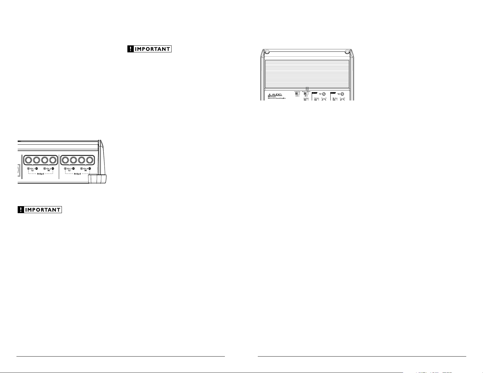
SPEAKER OUTPUTS
The M400/4’s speaker outputs are designed
to accept 16 AWG - 8 AWG wire. To connect the
speaker wires to the amplifier, first back out the
set screws on the top of the terminal block, using
the supplied 2.5 mm hex wrench. Strip 1/2 inch
(12 mm) of insulation from the end of each wire
and insert the bare wire into the terminal block,
seating it firmly so that no bare wire is exposed.
While holding the wire in place, tighten the set
screw firmly, taking care not to strip the head of
the screw.
Each pair of the M400/4’s channels are designed
to deliver power into speaker loads equal to
or greater than 2 ohms when using a “stereo”
configuration and speaker loads equal to or greater
than 4 ohms when using a “bridged” configuration.
Speaker loads below 2 ohms nominal per
channel (or 4 ohms bridged) are not
recommended and may cause the amplifier
to initiate a protection mode which reduces
power output.
BRIDGING CONSIDERATIONS
Bridging is the practice of combining the
output of two amplifier channels to drive a single
load. When bridged, each channel produces
signals of equal magnitude, but opposite polarity.
The combined output of the two channels
provides twice the output voltage available from a
single channel. The M400/4 has been designed for
bridging of its channel pairs without the need for
input inversion adaptors.
To bridge a pair of channels, use the “Left +”
and “Right –” speaker connectors only (the
“Left –” and “Right +” remain unused). When
bridged, each channel will deliver optimum
power into a 4 ohm load.
When a pair of channels are bridged, they
will deliver 200W x 1 into a 4 ohm load or
150W x 1 into an 8 ohm load. Operating a
pair of bridged channels into a load lower
than 4 ohms is not recommended.
Because a bridged pair of channels requires
that both channels receive input, you need to
connect both left and right inputs to the source
unit. Connection of only one input will result in
reduced power output, increased distortion and
can cause the amplifier to overheat.
Do not do this!
When a pair of the M400/4’s channels are
operating in bridged mode, the output will be in
mono (only one channel). This mono channel
can contain right channel only information,
left channel only information or the sum of
the information from both the right and left
channels. In order to achieve one of these options,
configure the inputs to that pair of channels in
one of these two ways:
1) Left Channel Only or Right Channel Only
Information: If you wish to send a left-only
or right-only signal to a pair of the M400/4’s
channels, use a “Y-Adaptor” to split the single
channel signal into both left and right RCA
inputs. This option is useful when using a
pair of the M400/4’s channels to drive left
channel speakers only and the other pair of
the M400/4’s channels to drive right channel
speakers only.
2) Left + Right Channel Information: When
bridged and fed by a stereo input, a pair of the
M400/4’s channels will automatically combine
the left and right channels into a summed
mono (left + right) channel. This option is
useful when using a pair of the M400/4’s
channels to drive a subwoofer system or a
summed mono center channel.
5) LED off / Amplifier Shuts Off Unexpectedly
The only condition that will shut down
an undamaged M600/6 completely is if battery
voltage or remote turn-on voltage drops below
10 volts. The “Status LED” will turn off when
this occurs. The amplifier will turn back on
when voltage climbs back above 11 volts. If this
is happening in your system, have your charging
system and power wiring inspected.
For more information on troubleshooting this
amplifier, refer to Appendix D (pages 16, 17).
SERVICING YOUR JL AUDIO AMPLIFIER
If your amplifier fails or malfunctions, please
return it to your authorized JL Audio dealer so
that it may be sent in to JL Audio for service.
There are no user serviceable parts or fuses inside
the amplifier. The unique nature of the circuitry
in the JL Audio amplifiers requires specifically
trained service personnel. Do not attempt
to service the amplifier yourself or through
unauthorized repair facilities. This will not only
void the warranty, but may result in the creation of
more problems within the amplifier.
If you have any questions about the installation or
setup of the amplifier not covered in this manual,
please contact your dealer or technical support.
JL Audio Technical Support:
(9 5 4) 4 43 -110 0
9:00 AM – 5:30 PM (Eastern Time Zone)
Monday - Friday
Loading ...
Loading ...
Loading ...