Loading ...
Loading ...
Loading ...
8 | JL Audio - M400/4 Owner’s Manual
9
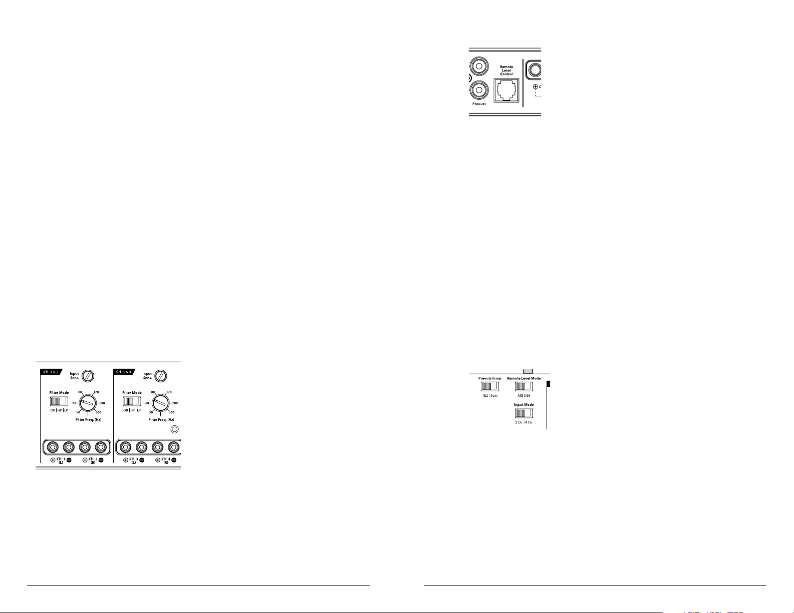
REMOTE LEVEL CONTROL OPTIONAL
With the addition of the optional Remote
Level Control (HD-RLC), you can control the
volume of one, or both channel pairs of the
M400/4 from a location of your choosing. This is
useful for subwoofer level control, cabin speaker
level control, zone volume control or even as a
master volume control for the entire system.
The HD-RLC connects to the jack labeled
“Remote Level Control” on the Connection Panel
of the amplifier using a standard telephone cable
(supplied with the HD-RLC). If desired, multiple
XD (and HD) amplifiers can be controlled from
a single HD-RLC controller using a simple phone
line “splitter” and multiple phone cables.
When connected to the amplifier, the
HD-RLC operates as follows. At full counter-
clockwise rotation, the audio will mute
completely. At full clockwise rotation the level
will be the same as if the HD-RLC was not
connected at all. In other words, it operates
strictly as a level attenuator.
“Remote Level Mode” Switch: This switch
allows you to assign the operation of the
HD-RLC to one, or both pairs of channels. In
the “A l l” position, the HD-RLC knob will affect
all three channel pairs equally. In the “3&4”
position, only the level of channels 3 and 4 will
be affected by the HD-RLC knob (Channels 1 &
2 will not).
PREOUTS
The M400/4 incorporates a pass-through
preamp output section, so that additional
amplifiers can be easily added to the system. This
pass-through pre-amp output can be configured
two different ways using the switch labeled
“Preouts From”.
1) “1&2”: The preamp output delivers the same
signal that is connected to the CH 1&2 Inputs.
This mode is useful for feeding a subwoofer
amplifier when the M400/4 is being used to
drive front and rear speaker systems. In this
mode, the preamp output signal will depend
only on the input signal level of CH 1&2,
allowing Channels 3&4 to be faded without
affecting the subwoofer level. If CH 1&2 is
faded in this mode, the signal level of the
preamp output will change accordingly.
2) “Sum”: When the M400/4 is being used to drive
front and rear speaker systems, this preamp
output mode will deliver a summed front/rear
stereo signal to a subwoofer amplifier, while
permitting fading of the front and rear speaker
systems from the source unit. This method
prevents a loss of signal to the subwoofer
amplifier when the system is faded to the front
or the rear by the head unit.
Note: In either mode, the preamp output signal is
not affected by any crossover filter selected (if the
input signal is full-range, the preamp output will
be full-range).
FILTER CONTROLS
Most speakers are not designed to reproduce
the full range of frequencies audible by the human
ear. For this reason, most speaker systems are
comprised of multiple speakers, each dedicated
to reproducing a specific frequency range. Filters
are used to select which frequency range is sent
to each section of a speaker system. The division
of frequency ranges to different speakers can be
done with passive filters (coils and/or capacitors
between the amplifier outputs and the speakers),
which are acceptable and commonly used
for filtering between mid-range speakers and
tweeters. Filtering between subwoofer systems
and satellite speaker systems is best done with
active filters, which cut off frequency content at
the input to the amplifier. Active filters are more
stable than passive filters and do not introduce
extraneous resistance, which can degrade
subwoofer performance.
The active filter built into each channel section
of the M400/4 can be used to eliminate potentially
harmful and/or undesired frequencies from
making their way through the amplifier sections
to the speaker(s). This serves to improve tonal
balance and to avoid distortion and possible
speaker failure. Correct use of these filters can
substantially increase the longevity and fidelity of
your audio system.
1) “Filter Mode” Control: The M400/4 employs a
12dB per octave filter for each pair of channels
(one filter for channels 1&2, another filter for
channels 3&4 and a third filter for channels
5&6). Each of these filters can be configured
independently into one of two filter types
or defeated completely by way of the three-
position “Filter Mode” switches:
“Off”: Defeats the filter completely, allowing
the full range of frequencies present at the
inputs to feed the amplifier. This is useful for
systems utilizing outboard active crossovers or
requiring full-range reproduction from one or
more of the M400/4’s channel pairs.
“LP” (Low-Pass): Configures the filter to
attenuate frequencies above the selected filter
frequency at a rate of 12dB per octave. This is
useful for connection of subwoofer(s) to one
or more of the M400/4’s channel pairs in a
bi-amplified system.
“HP” (High-Pass): Configures the filter to
attenuate frequencies below the selected filter
frequency at a rate of 12dB per octave. This is
useful for connection of component speakers to
one or more of the M400/4’s channel pairs in a
bi-amplified system.
2) “Filter Freq. (Hz)” The filter frequency
markings surrounding this rotary control
are for reference purposes and are generally
accurate to within 1/3 octave or better. If you
would like to select the filter cutoff frequency
with a higher level of precision, consult the
chart in Appendix B (page 15).
Tuning Hint: If you are using the M400/4
to drive a subwoofer system (“LP” mode), a
component satellite speaker system (“HP” mode)
or both, 80 Hz is a good baseline “Filter Freq.
(Hz)” setting. After properly adjusting the “Input
Sens.”, as outlined in Appendix A (page 14), you
can fine tune the “Filter Freq. (Hz)” control to
achieve the desired system frequency response.
Loading ...
Loading ...
Loading ...