
OmniTouch 7
TM
Touchscreen
7" Color Touchscreen
Installation Guide
WEB VERSION

TABLE OF CONTENTS
SPECIFICATIONS....................................................................................2
DESCRIPTION.........................................................................................3
PLANNING...............................................................................................3
Wiring Requirements....................................................................3
INSTALLATION........................................................................................4
REMOVING THE TOUCHSCREEN...........................................................7
CONFIGURING THE TOUCHSCREEN.....................................................8
Controller Settings........................................................................8
Page 1
WEB VERSION

SPECIFICATIONS
Size:
Mounting Bracket Cutout: 6.125" W x 4.625" H
Overall Dimensions: 7.375" W x 5.25" H x 0.55" D
LCD View Area: 7" diagonal
Display:
Resolution: 800x480
Voltage:
Operating Voltage (PoE): 42 - 57 VDC
Nominal Voltage (PoE): 48 VDC
Nominal Voltage (Aux): 12 VDC
Power:
Power Consumption: 5.4 Watts, maximum
Page 2
WARNINGS AND CAUTIONS
• WARNING: TO AVOID DEATH OR SERIOUS PERSONAL INJURY never
push objects of any kind into this product through openings, as they may touch
dangerous voltages.
• WARNING: TO AVOID DEATH OR SERIOUS PERSONAL INJURY never touch
uninsulated wires or terminals unless the wiring has been disconnected at the
network interface.
• Read and understand all instructions. Follow all warnings and instructions marked
on the product.
• Do not use this product near water - e.g., near a tub, wash basin, kitchen sink or
laundry tub, in a wet basement, or near a swimming pool.
• Never install communications wiring or components during a lightning storm.
• Never install communications components in wet locations unless the components
are designed specifically for use in wet locations.
• Use caution when installing or modifying communications wiring or components.
• SAVE THESE INSTRUCTIONS.
WEB VERSION

DESCRIPTION
The Model 99A00 OmniTouch 7 Touchscreen with Video is a colorful
network touchscreen interface for Leviton Security & Automation
controllers. The OmniTouch 7 features graphics for control of lights and
small appliances, to monitor and adjust security and temperatures, pool
and spa settings, ventilation, audio distribution, home theater equipment,
surveillance video, and other essential elements controlled by a Leviton
home automation system.
PLANNING
The OmniTouch 7 is an IEEE 802.3af compliant Power over Ethernet
(PoE) Powered Device (PD). The OmniTouch 7 receives its power over
the same cable that connects the OmniTouch 7 to the network, using a
Power Sourcing Equipment (PSE) device, such as a PoE network switch,
hub, or power injector.
It is very important to plan where the OmniTouch 7 Touchscreen will be
installed. Each OmniTouch 7 Touchscreen must be installed within 100
meters (328 feet) of a Power Sourcing Equipment (PSE) device.
In selecting a place to mount the touchscreen, be sure to avoid an area
where studs, plumbing, or electrical wiring may be located behind the
wallboard. Use a stud finder or probe to locate a suitable mounting
position. The mounting area should be at least 2” deep. It should be
mounted so that the display is at or slightly below eye level.
Wiring Requirements
When connecting an OmniTouch 7 to the network, a Cat-5 (4-pair) cable
is required for operation. Run the Cat-5 cable between the location of
the PoE network switch, hub, or power injector and the location of the
OmniTouch 7.
The maximum distance between the Power Sourcing Equipment (PSE)
device and the OmniTouch 7 and is 100 meters (328 feet). Terminate
both ends of the Cat-5 cable with 8-position modular connectors to make
a standard straight through network patch cable.
Page 3
WEB VERSION
INSTALLATION
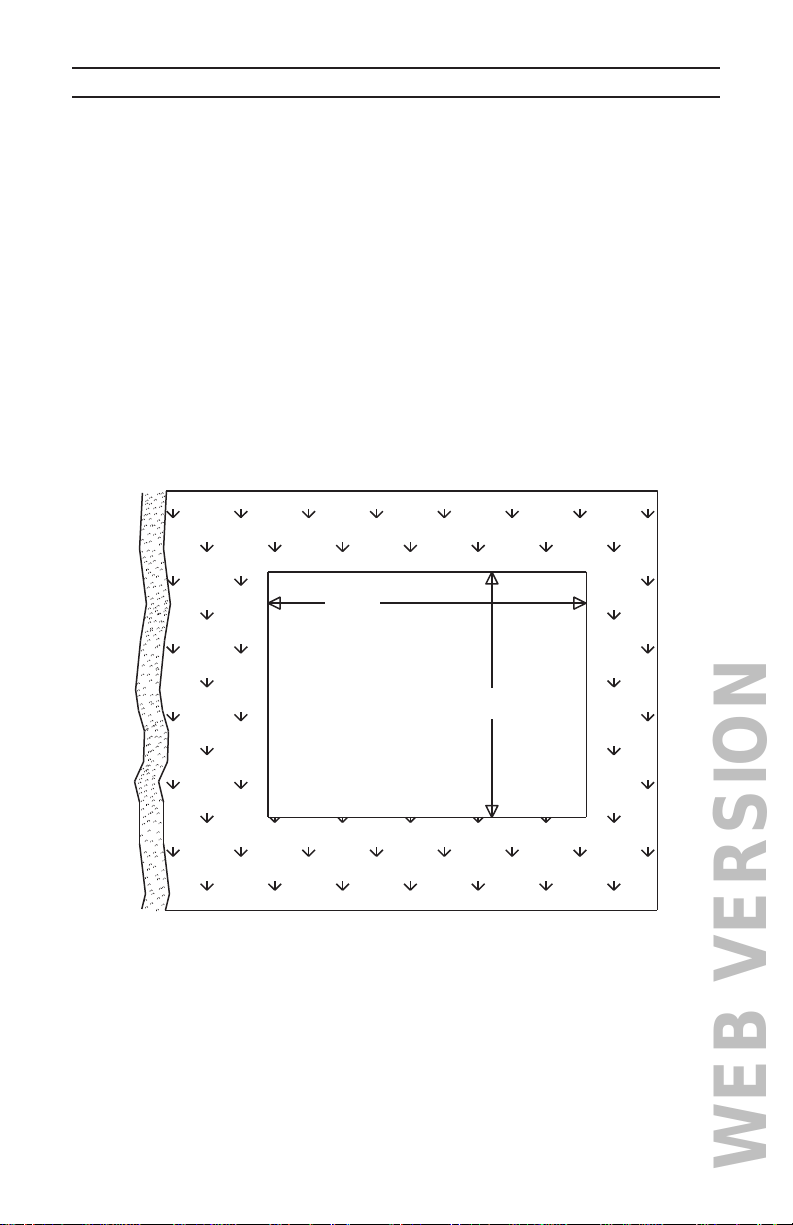
1) Make the cutout for the touchscreen
Tape the template (Installation Template for OmniTouch 7
Touchscreen) onto the wall, ensuring that it is level and plumb.
Use a sharp utility knife to cut along the 4 straight dotted lines on
the template. This will score the wall surface below and transfer the
template outline to the wall.
Remove the template and CAREFULLY cut through the wall material
along the inside of the scored line. Remember – it is always easier
to make the hole larger than it is to put back material that has been
removed!
Figure 1
Page 4
6.125”
4.625”
WEB VERSION
Page 5
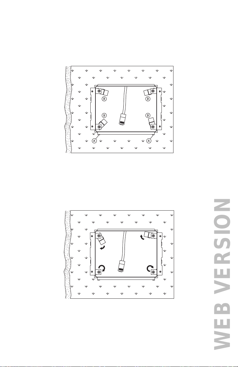
2) Install the mounting bracket into the cutout
a. Insert the mounting bracket into the wall cutout with the flanges
(marked "A" in Figure 2) at the bottom and retention clips (marked
"B" in Figure 2) rotated to the interior of the bracket as shown.
Figure 2
b. Rotate each of the retention clips clockwise (as shown in Figure
3) so that the clip grasps the back of the wallboard and the clip
stop comes to rest.
Figure 3
c. Tighten the retention clip screws by turning clockwise.
WEB VERSION
B
B
B
B
A
B
B
B
B
A
Page 6
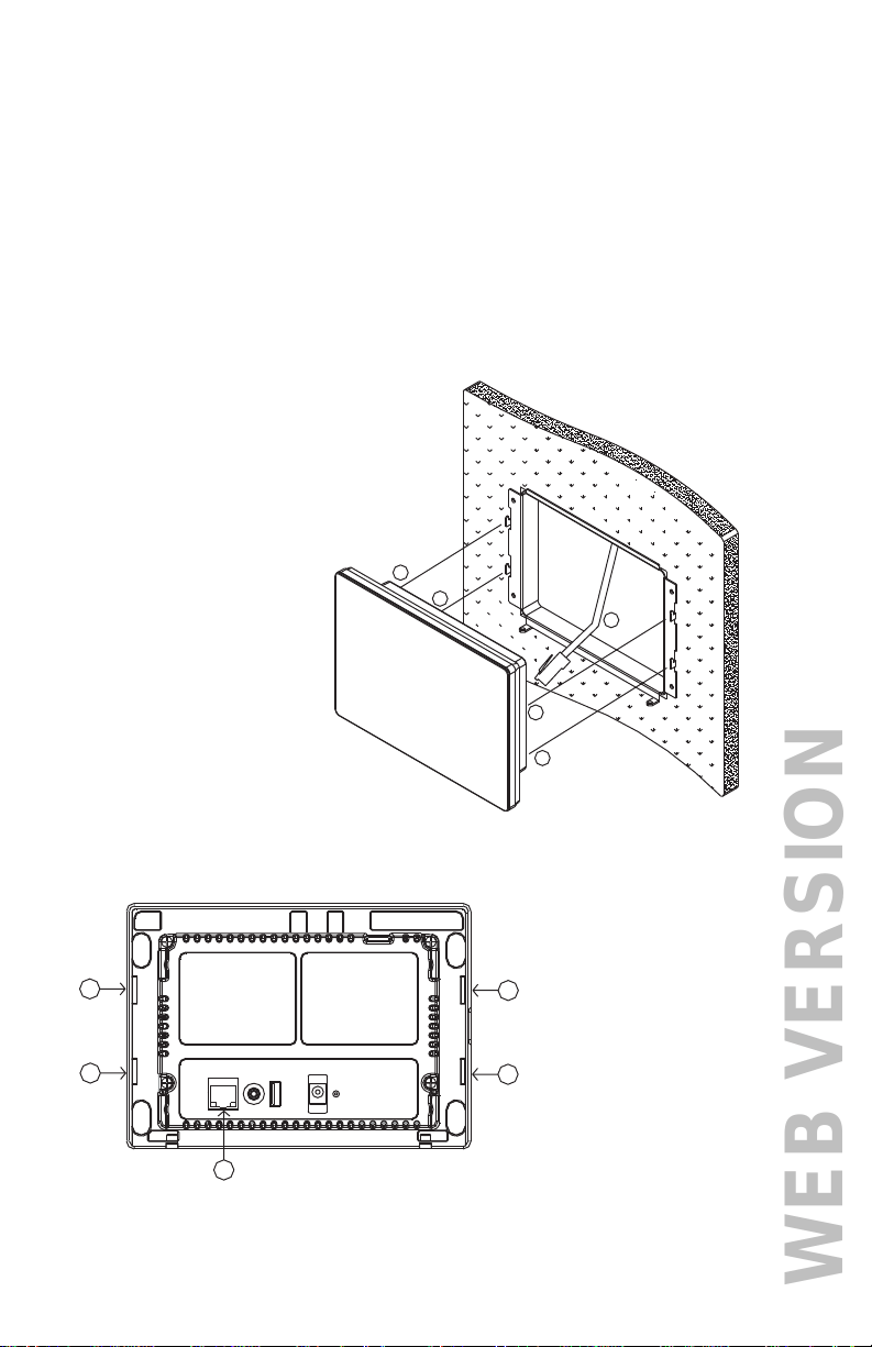
3) Installing the touchscreen
a. Insert the 8-position modular cable (marked "A" in Figure 4) into
the RJ-45 connector (LAN/POE) on the touchscreen (marked "A"
in Figure 5).
b. Align the tabs on the mounting bracket (marked "B" in Figure
4) with the slots on the touchscreen (marked "B" in Figure 5).
Attach the touchscreen to the mounting bracket by inserting the
tabs on the bracket into the mating slots on the touchscreen and
then gently pushing downward to lock into place.
Figure 4
Figure 5
WEB VERSION
Page 7
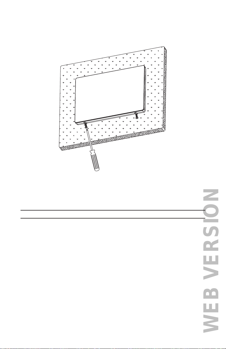
REMOVING THE TOUCHSCREEN
After installation, if it is necessary to remove the touchscreen from the
wall:
a) Remove the screws that secure the touchscreen to the mounting
bracket.
b) Push the touchscreen upward and then lift it away from the wall.
Figure 6
c. Secure the touchscreen to the mounting bracket flanges using
the provided screws.
WEB VERSION

Page 8
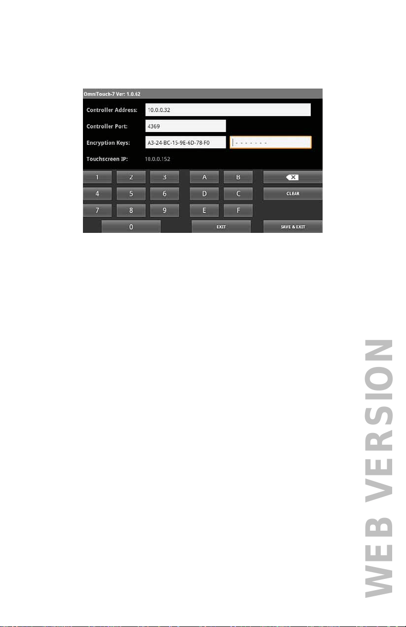
CONFIGURING THE TOUCHSCREEN
When power is first connected to the OmniTouch 7 touchscreen, if the
touchscreen hasn’t previously been configured to communicate with
the Leviton controller, the touchscreen Controller Settings screen is
displayed.
The IP address of the OmniTouch7 is displayed next to "Touchscreen IP".
Use the keyboard to enter the data in each of the edit boxes:
• After all controller connection settings have been entered and
confirmed, press the
"Save & Exit" button to save the settings and connect to the
controller.
• Use the "Exit" button to exit the Controller Settings screen
without saving any changes that were made.
• Use the “Clear” button to clear all of the content in the currently
selected edit box.
Controller Settings
To connect the OmniTouch 7 to a Leviton controller, enter the Leviton
controller network connection information:
1. Touch the edit box to the right of "Controller Address:" and enter
the IP address or hostname of the Leviton controller by pressing
the respective keys on the keyboard.
The controller’s local network IP address or hostname is used
to identify the Leviton controller on the network. The format of
the IP address is a numeric address entered as four numbers
separated by periods.
WEB VERSION
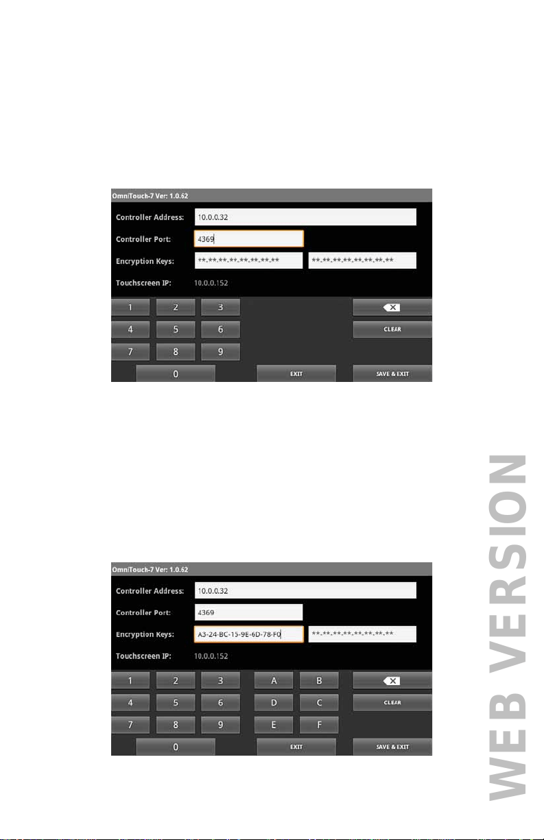
2. Touch the edit box to the right of "Controller Port:" and enter the
port number of the Leviton controller by pressing the respective
keys on the keyboard.
The controller’s local network port number identifies the logical
channel to the Leviton controller. In most installations, the default
port number of "4369" can remain the same. Port numbers range
from 0 to 65535.
3. Touch the first edit box to the right of "Encryption Keys:" and
enter Encryption Key 1 for the Leviton controller by pressing the
respective keys on the keyboard.
The Encryption Keys are used to encrypt and decrypt the data
between the Leviton controller and the OmniTouch 7. This key
consists of 16 bytes (16 2-digit values from 0-9 and/or the letters
A-F). It is entered in two parts consisting of 8 bytes (8 2-digit
values) in each edit box, with each byte separated by a hyphen.
Page 9
WEB VERSION
4. Touch the second edit box to the right of "Encryption Keys:" and
enter Encryption Key 2 for the Leviton controller by pressing the
respective keys on the keyboard.
Page 10
5. After all controller connection settings have been entered and
confirmed, press the "Save" button at the bottom right of the
screen to save the settings and connect to the Leviton controller.
WEB VERSION

DI-02X-99A00-05D (99I00)© 2016 Leviton Mfg. Co., Inc.
FOR CANADA ONLY
For warranty information and/or product returns, residents of Canada should contact Leviton in writing
at Leviton Manufacturing of Canada Ltd to the attention of the Quality Assurance Department,
165 Hymus Blvd, Pointe-Claire (Quebec), Canada H9R 1E9 or by telephone at 1 800 405-5320.
For Technical Assistance Call: 800-824-3005 - www.leviton.com
LEVITON LIMITED WARRANTY
Leviton warrants to the original consumer purchaser and not for the benefit of anyone else that
products manufactured by Leviton under the Leviton brand name (“Product”) will be free from defects
in material and workmanship for the time periods indicated below, whichever is shorter: • OmniPro
II and Lumina Pro: three (3) years from installation or 42 months from manufacture date. • Omni
LTe, Omni IIe, and Lumina: two (2) years from installation or 30 months from manufacture date. •
BitWise Controllers, Accessories: two (2) years from installation or 30 months from manufacture
date. • Lumina Gateway Controllers: two (2) years from installation or 30 months from manufacture
date. • Thermostats, Accessories: two (2) years from installation or 30 months from manufacture
date. • Batteries: Rechargeable batteries in products are warranted for ninety (90) days from date
of purchase. Note: Primary (non-rechargeable) batteries shipped in products are not warranted.
Products with Windows
®
Operating Systems: During the warranty period, Leviton will restore
corrupted operating systems to factory default at no charge, provided that the product has been used
as originally intended. Installation of non-Leviton software or modification of the operating system voids
this warranty. Leviton’s obligation under this Limited Warranty is limited to the repair or replacement,
at Leviton’s option, of Product that fails due to defect in material or workmanship. Leviton reserves
the right to replace product under this Limited Warranty with new or remanufactured product. Leviton
will not be responsible for labor costs of removal or reinstallation of Product. The repaired or
replaced product is then warranted under the terms of this Limited Warranty for the remainder of the
Limited Warranty time period or ninety (90) days, whichever is longer. This Limited Warranty does
not cover PC-based software products. Leviton is not responsible for conditions or applications
beyond Leviton’s control. Leviton is not responsible for issues related to improper installation,
including failure to follow written Installation and operation instructions, normal wear and
tear, catastrophe, fault or negligence of the user or other problems external to the Product. To
view complete warranty and instructions for returning product, please visit us at www.leviton.com.
TRADEMARK DISCLAIMER: Use herein of third party trademarks, service marks, trade names,
brand names and/or product names are for informational purposes only, are/may be the trademarks of
their respective owners; such use is not meant to imply affiliation, sponsorship, or endorsement.
FCC COMPLIANCE
This equipment has been tested and found to comply with the limits for a Class B digital device,
pursuant to part 15 of the FCC Rules. These limits are designed to provide reasonable protection
against harmful interference in a residential installation. This equipment generates, uses and can
radiate radio frequency energy and, if not installed and used in accordance with the instructions, may
cause harmful interference to radio communications. However, there is no guarantee that interference
will not occur in a particular installation. If this equipment does cause harmful interference to radio
or television reception, which can be determined by turning the equipment off and on, the user is
encouraged to try to correct the interference by one or more of the following measures:
- Reorient or relocate the receiving antenna.
- Increase the separation between the equipment and receiver.
- Connect the equipment into an outlet on a circuit different from that to which the receiver is connected.
- Consult the dealer or an experienced radio/TV technician for help.
PATENTS
Licensed under one or more of the following U.S. Patent Numbers : 7,457,250; 8,155,012; 8,902,760;
8,942,107; and 9,049,019
WEB VERSION