©2018 FCA US LLC. All Rights Reserved. Jeep is a registered trademark of FCA US LLC.
App Store is a registered trademark of Apple Inc. Google Play Store is a registered trademark of Google.
Whether it’s providing information about specific product features, taking a tour through your
vehicle’s heritage, knowing what steps to take following an accident or scheduling your next
appointment, we know you’ll find the app an important extension of your Jeep
brand vehicle.
Simply download the app, select your make and model and enjoy the ride.
To get this app, go directly to the App Store® or Google Play® Store and enter the search keyword “JEEP”
(U.S. residents only).
www.jeep.com⁄en ⁄owners (U.S.) provides special oers tailored to your needs, customized vehicle galleries,
personalized service records and more. To get this information, just create an account and check back often.
Get warranty and other information online – you can review and print or download a copy of the Owner’s
Manual, Navigation ⁄ Uconnect manuals and the limited warranties provided by FCA US LLC for your vehicle
by visiting www.mopar.com (U.S.) or www.owners.mopar.ca (Canada). Click on the applicable link in the
“Popular Topics” area of the mopar.com (U.S.) or www.owners.mopar.ca (Canada) homepage and follow
the instructions to select the applicable year, make and model of your vehicle.
DOWNLOAD A FREE ELECTRONIC COPY of the most up-to-date Owner’s Manual,
media and warranty booklet by visiting:
www.mopar.com/en-us/care/owners-manual.html (U.S. residents);
www.owners.mopar.ca (Canadian residents).
Jeep.com (U.S.)
Jeep.ca (Canada)
19WK-926-AA
Second Edition
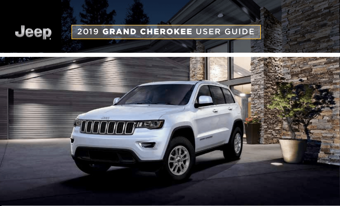
2019 GRAND CHEROKEE USER GUIDE

Driving and Alcohol
Drunk driving is one of the most frequent causes of
collisions. Your driving ability can be seriously impaired with
blood alcohol levels far below the legal minimum. If you are
drinking, don’t drive. Ride with a designated non-drinking
driver, call a cab, a friend or use public transportation.
WARNING!
Driving after drinking can lead to a collision.
Your perceptions are less sharp, your reflexes are slower
and your judgment is impaired when you have been
drinking. Never drink and then drive.
Important
Get warranty and other information online – you can review and
print or download a copy of the Owner’s Manual, Navigation/
Uconnect manuals and the limited warranties provided by
FCA US LLC for your vehicle by visiting www.mopar.com (U.S.)
or www.owners.mopar.ca (Canada). Click on the applicable
link in the “Popular Topics” area of the www.mopar.com (U.S.)
or www.owners.mopar.ca (Canada) homepage and follow the
instructions to select the applicable year, make and model of
your vehicle.
If you are the first registered retail owner of your vehicle, you may
obtain a complimentary printed copy of the Warranty Booklet by
calling 1-877-426-5337 (U.S.) or 1-800-387-1143 (Canada) or by
contacting your dealer.
The driver’s primary responsibility is the safe operation of the
vehicle. Driving while distracted can result in loss of vehicle control,
resulting in a collision and personal injury. FCA US LLC strongly
recommends that the driver use extreme caution when using any
device or feature that may take their attention o the road.
Use of any electrical devices, such as cellular telephones, computers,
portable radios, vehicle navigation or other devices, by the driver
while the vehicle is moving is dangerous and could lead to a serious
collision. Texting while driving is also dangerous and should never be
done while the vehicle is moving.
If you find yourself unable to devote your full attention to vehicle
operation, pull o the road to a safe location and stop your vehicle.
Some states or provinces prohibit the use of cellular telephones or
texting while driving. It is always the driver’s responsibility to comply
with all local laws.
This guide has been prepared to help you get quickly
acquainted with your new Jeep
brand vehicle and to
provide a convenient reference for common
questions. However, it is not a substitute for your
Owner’s Manual.
For complete operational instructions, maintenance
procedures and important safety messages, please
consult your Owner’s Manual, Navigation/Uconnect
manuals found on the website on the back cover
and other Warning Labels in your vehicle.
Not all features shown in this guide may apply
to your vehicle. For additional information on
accessories to help personalize your vehicle, visit
www.mopar.com (U.S.), www.mopar.ca (Canada)
or your local Jeep
brand dealer.
WARNING: Operating, servicing and maintaining a passenger vehicle or off-road
highway motor can expose you to chemicals including engine exhaust, carbon monoxide,
phthalates, and lead, which are known to the State of California to cause cancer and
birth defects or other reproductive harm. To minimize exposure, avoid breathing exhaust,
do not idle the engine except as necessary, service your vehicle in a well-ventilated area
and wear gloves or wash your hands frequently when servicing your vehicle. For more
information go to:
www.p65Warnings.ca.gov/passenger-vehicle

Congratulations on selecting your new FCA
US LLC vehicle. Be assured that it represents
precision workmanship, distinctive styling,
and high quality.
ALWAYS drive safely and pay attention to the
road. ALWAYS drive safely with your hands on
the steering wheel. You have full responsibility
and assume all risks related to the use of the
features and applications in this vehicle. Only
use the features and applications when it is
safe to do so. Failure to do so may result in an
accident involving serious injury or death.
This guide illustrates and describes the op-
eration of features and equipment that are
either standard or optional on this vehicle.
This guide may also include a description of
features and equipment that are no longer
available or were not ordered on this vehicle.
Please disregard any features and equipment
described in this guide that are not available
on this vehicle. FCA US LLC reserves the
right to make changes in design and specifi-
cations and/or make additions to or improve-
ments to its products without imposing any
obligation upon itself to install them on prod-
ucts previously manufactured.
This User Guide has been prepared to help
you quickly become acquainted with the im-
portant features of your vehicle. It contains
most things you will need to operate and
maintain the vehicle, including emergency
information.
When it comes to service, remember that your
authorized dealer knows your Jeep
®
vehicle
best, has factory-trained technicians and
genuine MOPAR
®
parts, and cares about your
satisfaction.
HOW TO FIND YOUR
OWNER’S MANUAL ONLINE
This publication has been prepared as a ref-
erence item to help you quickly become ac-
quainted with the most important features
and processes of your vehicle. It contains
most things you will need to operate and
maintain the vehicle, including emergency
information and procedures.
This User Guide is not a replacement for the full
Owner’s Manual, and does not fully cover every
operation and procedure possible with your ve-
hicle.
For more detailed descriptions of the topics
discussed in this User Guide, as well as
information covering features and processes
not covered in this User Guide, the full ve-
hicle Owner’s Manual can be accessed for
free online in a printer-friendly PDF format.
To get the full Owner’s Manual or applicable
supplement for your vehicle, follow the appro-
priate web address below:
www.mopar.com/en-us/care/owners-manual.html
(U.S. Residents)
www.owners.mopar.ca (Canadian Residents)
FCA US LLC is committed to protecting our
environment and natural resources. By con-
verting from paper to electronic delivery for
the majority of the user information for your
vehicle, together we greatly reduce the de-
mand for tree-based products and lessen the
stress on our environment.
WELCOME FROM FCA US LLC
1
HOW TO USE THIS MANUAL
Essential Information
Each time direction instructions (left/right or
forwards/backwards) about the vehicle are
given, these must be intended as regarding
an occupant in the driver's seat. Special
cases not complying with this rule will be
properly specified in the text.
The figures in this User Guide are provided by
way of example only: this might imply that
some details of the image do not correspond
to the actual arrangement of your vehicle.
In addition, the User Guide has been con-
ceived considering vehicles with the steering
wheel on the left side; it is therefore possible
that in vehicles with the steering wheel on the
right side, the position or construction of
some controls is not exactly mirror-like with
respect to the figure.
To identify the chapter with the information
needed you can consult the index at the end
of this User Guide.
Chapters can be rapidly identified with dedi-
cated graphic tabs, at the side of each odd
page. A few pages further there is a key for
getting to know the chapter order and the
relevant symbols in the tabs. There is always
a textual indication of the current chapter at
the side of each even page.
Symbols
Some vehicle components have colored la-
bels whose symbols indicate precautions to
be observed when using this component.
Refer to “Warning Lights and Messages” in
“Getting To Know Your Instrument Panel” for
further information on the symbols used in
your vehicle.
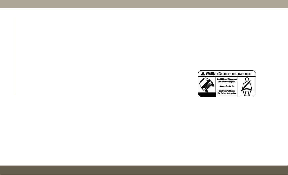
ROLLOVER WARNING
Utility vehicles have a significantly higher
rollover rate than other types of vehicles. This
vehicle has a higher ground clearance and a
higher center of gravity than many passenger
vehicles. It is capable of performing better in
a wide variety of off-road applications. Driven
in an unsafe manner, all vehicles can go out
of control. Because of the higher center of
gravity, if this vehicle is out of control it may
roll over while some other vehicles may not.
Do not attempt sharp turns, abrupt maneu-
vers, or other unsafe driving actions that can
cause loss of vehicle control. Failure to oper-
ate this vehicle safely may result in a colli-
sion, rollover of the vehicle, and severe or
fatal injury. Drive carefully.
Failure to use the driver and passenger seat
belts provided is a major cause of severe or
fatal injury. In fact, the U.S. government
notes that the universal use of existing seat
belts could cut the highway death toll by
10,000 or more each year and could reduce
disabling injuries by two million annually.
Rollover Warning Label
HOW TO USE THIS MANUAL
2

In a rollover crash, an unbelted person is
significantly more likely to die than a person
wearing a seat belt. Always buckle up.
WARNINGS AND CAUTIONS
While reading this User Guide you will find a
series of WARNINGS to be followed to pre-
vent incorrect use of components which
could cause accidents or injuries.
There are also CAUTIONS that must be fol-
lowed to prevent against procedures that
could result in damage to your vehicle.
HOW TO USE THIS MANUAL
3

4


WELCOME FROM FCA US LLC
HOW TO FIND YOUR OWNER’S MANUAL ONLINE ....1
HOW TO USE THIS MANUAL
HOW TO USE THIS MANUAL ...............2
Essential Information ................2
Symbols ........................2
ROLLOVER WARNING ...................2
WARNINGS AND CAUTIONS ...............3
GRAPHICAL TABLE OF CONTENTS
INSTRUMENT PANEL ..................11
INTERIOR .........................12
GETTING TO KNOW YOUR VEHICLE
KEYS ...........................13
KeyFob ....................... 13
IGNITIONSWITCH ....................14
Keyless Enter-N-Go — Ignition .........14
REMOTE STARTING SYSTEM — IF EQUIPPED ....16
How To Use Remote Start ............16
To Enter Remote Start Mode ...........17
General Information ...............17
VEHICLE SECURITY ALARM — IF EQUIPPED .....17
To Arm The System ................17
To Disarm The System ..............18
Tamper Alert ....................18
DOORS ..........................18
Keyless Enter-N-Go — Passive Entry ...... 18
Child-Protection Door Lock System —
Rear Doors ..................... 22
SEATS ..........................23
Driver Memory Seat — If Equipped .......23
Heated Seats .................... 25
Front Ventilated Seats ..............27
HEAD RESTRAINTS ...................27
Supplemental Active Head Restraints —
Front Seats .....................28
Adjustment — Rear Seats ............30
Head Restraint Removal — Rear Seats .... 30
STEERING WHEEL ....................31
Manual Tilt/Telescoping Steering Column —
If Equipped .....................31
Power Tilt/Telescoping Steering Column —
If Equipped .....................32
Heated Steering Wheel — If Equipped .....32
MIRRORS ........................33
Power Folding Outside Mirrors —
If Equipped .....................33
Tilt Side Mirrors In Reverse (Available With
Memory Seat Only) — If Equipped .......34
EXTERIOR LIGHTS ...................34
Headlight Switch ..................34
Multifunction Lever ................ 35
Daytime Running Lights — If Equipped ....35
High/Low Beam Switch .............. 36
Automatic High Beam — If Equipped .....36
Flash-To-Pass ...................36
Automatic Headlights — If Equipped ..... 36
Parking Lights And Panel Lights ........36
Headlights On Automatically With Wipers . . . 36
Headlight Delay ..................37
Lights-On Reminder ................ 37
Fog Lights — If Equipped ............37
Turn Signals ....................38
Battery Saver .................... 38
WINDSHIELD WIPERS AND WASHERS .........38
Windshield Wiper Operation ........... 38
Rain Sensing Wipers — If Equipped ......40
Rear Window Wiper/Washer ...........41
CLIMATE CONTROLS ..................41
Automatic Climate Controls Overview .....42
Climate Control Functions ............48
Automatic Temperature Control (ATC) .....48
Operating Tips ...................49
WINDOWS ........................50
Power Window Controls ..............50
Auto-Down Feature ................51
Auto-Up Feature With Anti-Pinch Protection
..51
Window Lockout Switch .............51
WindBuffeting ..................51
POWER SUNROOF — IF EQUIPPED ...........52
Opening Sunroof ..................52
Closing Sunroof .................. 52
Sunshade Operation ................53
Pinch Protect Feature ............... 53
Venting Sunroof — Express ...........53
Sunroof Maintenance ...............53
Relearn Procedure .................53
COMMANDVIEW SUNROOF WITH POWER SHADE —
IF EQUIPPED ......................54
Opening Sunroof ..................55
Closing Sunroof .................. 55
Opening Power Shade ...............55
Closing Power Shade ............... 56
Pinch Protect Feature ............... 56
Venting Sunroof — Express ...........56
Sunroof Maintenance ...............56
HOOD ..........................57
To Open The Hood .................57
To Close The Hood .................57
TABLE OF CONTENTS
6

LIFTGATE .........................57
Opening .......................57
Closing ........................58
Power Liftgate — If Equipped .........59
UNIVERSAL GARAGE DOOR OPENER (HOMELINK) . . . 60
Before You Begin Programming HomeLink . . 61
Erasing All The HomeLink Channels ......61
Identifying Whether You Have A Rolling Code
Or Non-Rolling Code Device ........... 61
Programming HomeLink To A Garage Door
Opener ........................ 62
Programming HomeLink To A Miscellaneous
Device ........................63
Reprogramming A Single HomeLink Button . . 63
General Information ................63
INTERNAL EQUIPMENT .................64
Power Outlets ....................64
Power Inverter ...................66
ROOF LUGGAGE RACK — IF EQUIPPED .........67
GETTING TO KNOW YOUR
INSTRUMENT PANEL
INSTRUMENT CLUSTER DISPLAY ............69
Instrument Cluster Display Location
AndControls ....................69
Oil Change Reset — If Equipped ........ 70
Instrument Cluster Display Selectable Items . . 71
Display Menu items ................71
TRIP COMPUTER .....................74
WARNING LIGHTS AND MESSAGES ..........74
RedWarningLights ................ 74
YellowWarningLights ...............77
YellowIndicatorLights ..............81
GreenIndicatorLights ..............82
WhiteIndicatorLights ..............83
BlueIndicatorLights ...............85
ONBOARD DIAGNOSTIC SYSTEM — OBD II ......85
Onboard Diagnostic System (OBD II)
Cybersecurity ....................85
EMISSIONS INSPECTION AND MAINTENANCE
PROGRAMS .......................86
SAFETY
SAFETY FEATURES ...................87
Anti-Lock Brake System (ABS) .........87
Electronic Brake Control System ........88
AUXILIARY DRIVING SYSTEMS .............98
Blind Spot Monitoring (BSM) —
If Equipped ..................... 98
Forward Collision Warning (FCW) With
Mitigation .....................102
Tire Pressure Monitor System (TPMS) .... 104
OCCUPANT RESTRAINT SYSTEMS ..........109
Occupant Restraint Systems Features ....109
Important Safety Precautions .........109
Seat Belt Systems ................110
Supplemental Restraint Systems (SRS) . . . 119
ChildRestraints .................129
Transporting Pets ................142
SAFETY TIPS .....................142
Transporting Passengers ............142
Exhaust Gas ...................143
Safety Checks You Should Make Inside The
Vehicle ......................143
Periodic Safety Checks You Should Make
OutsideTheVehicle ...............145
STARTING AND OPERATING
STARTING THE ENGINE — GAS ............146
Automatic Transmission ............. 146
Normal Starting .................146
STARTING THE ENGINE — 3.0L DIESEL ENGINE . . 149
Automatic Transmission ............. 150
Normal Starting .................150
ENGINE BREAK-IN RECOMMENDATIONS .......151
3.6L & 5.7L Engines ..............151
Diesel Engine ...................152
SRT Engines ................... 152
STOP/START SYSTEM — IF EQUIPPED ........153
Automatic Mode ................. 153
Possible Reasons The Engine Does Not
Autostop .....................154
To Start The Engine While In Autostop
Mode .......................154
To Manually Turn Off The Stop/Start
System ......................155
To Manually Turn On The Stop/Start System . 155
System Malfunction ...............155
AUTOMATIC TRANSMISSION .............155
Ignition Park Interlock ..............156
B
rake/Transmission Shift Interlock System
. . 157
Fuel Economy (ECO) Mode ...........157
Eight–Speed Automatic Transmission ..... 158
SPORT MODE — IF EQUIPPED ............160
FOUR WHEEL DRIVE OPERATION ...........160
Quadra-Trac I Operating Instructions/
Precautions — If Equipped ...........160
Quadra-Trac II Operating Instructions/
Precautions — If Equipped ...........160
7

ShiftPositions ..................161
Shifting Procedures ...............162
Quadra-Drive II System — If Equipped ....164
QUADRA-LIFT — IF EQUIPPED ............164
Description ....................164
Air Suspension Modes .............167
Instrument Cluster Display Messages .....167
Operation .....................167
SELEC-TERRAIN — IF EQUIPPED ...........169
Selec-Terrain Mode Selection .........169
Instrument Cluster Display Messages .....169
SELEC-TRACK — IF EQUIPPED (SRT) ........170
Custom .......................170
Active Damping System .............171
Launch Control— If Equipped .........171
GuidelinesForTrackUse ............172
SPEED CONTROL — IF EQUIPPED ..........174
ToActivate ....................175
To Set A Desired Speed ............ 175
To Resume Speed ................175
To Deactivate ................... 175
ADAPTIVE CRUISE CONTROL (ACC) —
IF EQUIPPED ......................176
To Activate/Deactivate .............. 176
To Set A Desired ACC Speed ..........176
To Resume ....................177
To Vary The Speed Setting ...........177
Setting The Following Distance In ACC ....178
General Information ...............179
PARKSENSE REAR PARK ASSIST — IF EQUIPPED . . 179
ParkSense Sensors ................179
ParkSense Warning Display ...........179
Enabling And Disabling ParkSense ......180
ParkSense System Usage Precautions ....180
PARKSENSE FRONT AND REAR PARK ASSIST —
IF EQUIPPED ......................181
ParkSense Sensors ................181
Enabling And Disabling ParkSense ......182
PARKSENSE ACTIVE PARK ASSIST SYSTEM —
IF EQUIPPED ......................182
Enabling And Disabling The ParkSense
Active Park Assist System ...........183
LANESENSE — IF EQUIPPED .............183
LaneSense Operation ..............183
Turning LaneSense On Or Off .........184
LaneSense Warning Message ..........184
Changing LaneSense Status ..........185
PARKVIEW REAR BACK UP CAMERA ........186
REFUELING THE VEHICLE — GASOLINE ENGINE . . . 187
Emergency Fuel Filler Door Release .....189
REFUELING THE VEHICLE — DIESEL ENGINE ....189
Avoid Using Contaminated Fuel ........191
Bulk Fuel Storage — Diesel Fuel .......191
Diesel Exhaust Fluid ...............192
TRAILER TOWING ...................195
Trailer Towing Weights (Maximum Trailer
Weight Ratings) — Non SRT ..........195
Trailer Towing Weights (Maximum Trailer
Weight Ratings) — Diesel ...........196
Trailer Towing Weights (Maximum Trailer
Weight Ratings) — SRT ............. 197
Trailer Hitch Receiver Cover Removal
(Summit Models) — If Equipped .......198
Trailer Hitch Receiver Cover Removal
(SRT Models) — If Equipped ......... 199
RECREATIONAL TOWING (BEHIND MOTORHOME,
ETC.) ..........................201
Towing This Vehicle Behind Another Vehicle . . 201
Recreational Towing — Two Wheel Drive
Models ....................... 202
Recreational Towing — Quadra-Trac I
(Single-Speed Transfer Case) Four-Wheel
Drive Models ...................202
Recreational Towing — Quadra–Trac II/
Quadra–Drive II Four-Wheel Drive Models . . 202
IN CASE OF EMERGENCY
HAZARD WARNING FLASHERS ............206
BULB REPLACEMENT .................206
Replacement Bulbs ...............206
Bulb Replacement ................207
FUSES .........................210
General Information ...............211
Underhood Fuses ................211
JACKING AND TIRE CHANGING ............216
Run Flat Tires — SRT Models ......... 216
Jack Location ...................216
Spare Tire Stowage ...............216
Preparations For Jacking ............217
Jacking Instructions ...............217
Road Tire Installation ..............221
JUMP STARTING ....................221
Preparations For Jump Start ..........222
Jump Starting Procedure ............ 223
REFUELING IN EMERGENCY ..............224
IF YOUR ENGINE OVERHEATS ............224
MANUAL PARK RELEASE ...............225
FREEING A STUCK VEHICLE ..............226
TOWING A DISABLED VEHICLE ............227
Two-Wheel Drive Models ............ 229
Four-Wheel Drive Models ............229
Emergency Tow Hooks — If Equipped ....230
TABLE OF CONTENTS
8

ENHANCED ACCIDENT RESPONSE SYSTEM (EARS)
. . 230
EVENT DATA RECORDER (EDR) ............230
SERVICING AND MAINTENANCE
SCHEDULED SERVICING ................231
Scheduled Servicing — Non-SRT .......231
Scheduled Servicing — SRT .......... 234
Scheduled Servicing — Diesel Engine ....238
ENGINE COMPARTMENT ...............242
3.6L Engine .................... 242
5.7L Engine .................... 243
6.2L Supercharged Engine ........... 244
6.4L Engine .................... 245
3.0L Diesel Engine ...............246
Checking Oil Level — Gasoline Engine ....247
Checking Oil Level — 3.0 Diesel Engine . . . 247
Adding Washer Fluid ...............247
Maintenance-Free Battery ........... 248
DEALER SERVICE ...................249
Air Conditioner Maintenance ......... 249
Windshield Wiper Blades ............ 251
Cooling System ..................255
Brake System ..................256
Automatic Transmission ............. 257
RAISING THE VEHICLE .................257
TIRES ..........................257
TireSafetyInformation .............257
Tires — General Information .........263
Tire Types ..................... 267
Spare Tires — If Equipped ...........268
Wheel And Wheel Trim Care ..........270
Tire Chains (Traction Devices) — Non-SRT
. . 271
Tire Chains (Traction Devices) — SRT .... 272
Tire Rotation Recommendations ........ 272
DEPARTMENT OF TRANSPORTATION UNIFORM TIRE
QUALITY GRADES ...................273
Treadwear .....................273
Traction Grades ..................274
Temperature Grades ...............274
INTERIORS .......................274
Seats And Fabric Parts .............274
Plastic And Coated Parts ............275
Leather Parts ...................275
Glass Surfaces ..................276
TECHNICAL SPECIFICATIONS
IDENTIFICATION DATA .................277
Vehicle Identification Number .........277
WHEEL AND TIRE TORQUE SPECIFICATIONS ....278
Torque Specifications ..............278
FUEL REQUIREMENTS — GASOLINE ENGINE ....279
3.6L Engine ...................279
5.7L Engine .................... 279
6.2L Supercharged And 6.4L Engine .....279
Materials Added To Fuel ............280
FUEL REQUIREMENTS – DIESEL ENGINE .......280
Diesel Fuel Specifications ...........281
FLUID CAPACITIES — NON SRT ...........282
FLUID CAPACITIES — SRT ..............282
FLUID CAPACITIES — DIESEL ............283
FLUIDS AND LUBRICANTS — NON-SRT .......284
Engine .......................284
Chassis .......................285
FLUIDS AND LUBRICANTS — SRT ..........286
Engine .......................286
Chassis .......................286
FLUIDS AND LUBRICANTS — DIESEL .........287
Engine .......................287
Chassis .......................289
MOPAR ACCESSORIES .................290
Authentic Accessories By Mopar ........290
MULTIMEDIA
CYBERSECURITY ...................292
UCONNECT 4 WITH 7-INCH DISPLAY .........293
Uconnect 4 At A Glance ............293
Drag & Drop Menu Bar ............. 294
Radio .......................295
Android Auto — If Equipped ..........296
Apple CarPlay Integration — If Equipped . . 298
UCONNECT SETTINGS .................299
OFF ROAD PAGES — IF EQUIPPED ..........299
Off Road Pages Status Bar ...........300
Vehicle Dynamics ................300
Suspension ....................301
PitchAndRoll ..................301
Accessory Gauges ................302
Selec-Terrain — If Equipped ..........302
TIPS CONTROLS AND GENERAL INFORMATION . . . 303
Steering Wheel Audio Controls .........303
Reception Conditions ..............303
Care And Maintenance .............303
Anti-Theft Protection ..............303
IPOD/USB/MEDIA PLAYER CONTROL .........304
Audio Jack (AUX) .................304
USBPort .....................304
Bluetooth Streaming Audio ...........305
9

UCONNECT REAR SEAT ENTERTAINMENT (RSE)
SYSTEM — IF EQUIPPED ...............305
Getting Started .................305
Dual Video Screen ................306
Blu-ray Disc Player ................306
Play Video Games ................310
Accessibility — If Equipped .......... 310
UCONNECT PHONE ...................311
Uconnect Phone (Bluetooth Hands Free
Calling) ......................311
Pairing (Wirelessly Connecting) Your Mobile
Phone To The Uconnect System ........313
Common Phone Commands (Examples) . . . 316
Mute (Or Unmute) Microphone During Call . . 316
Transfer Ongoing Call Between Handset
AndVehicle ...................316
Phonebook ....................316
Voice Command Tips ..............317
Changing The Volume .............. 317
UsingDoNotDisturb ..............317
Incoming Text Messages ............ 318
Helpful Tips And Common Questions To
Improve Bluetooth Performance With Your
Uconnect System ................ 319
UCONNECT VOICE RECOGNITION QUICK TIPS ....320
Introducing Uconnect ..............320
GetStarted ....................320
Basic Voice Commands ............. 321
Radio ........................321
Media .......................322
Phone ....................... 322
Voice Text Reply — If Equipped ........323
Climate ......................324
Siri Eyes Free — If Equipped .........325
DoNotDisturb .................. 325
Android Auto — If Equipped ..........326
Apple CarPlay — If Equipped ......... 326
General Information ...............327
Additional Information .............328
CUSTOMER ASSISTANCE
IF YOU NEED ASSISTANCE ..............329
FCA US LLC Customer Center .........329
FCA Canada Inc. Customer Center ......329
In Mexico Contact ................ 329
Puerto Rico And U.S. Virgin Islands ..... 329
Customer Assistance For The Hearing Or
Speech Impaired (TDD/TTY) .......... 330
ServiceContract .................330
WARRANTY INFORMATION ..............330
REPORTING SAFETY DEFECTS ............331
In The 50 United States And Washington,
D.C. ........................331
In Canada ..................... 331
PUBLICATION ORDER FORMS .............331
INDEX
.......................333
TABLE OF CONTENTS
10
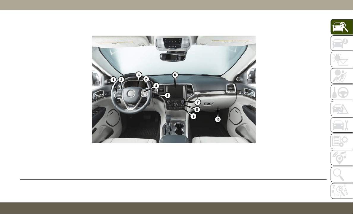
INSTRUMENT PANEL
Instrument Panel
1 — Instrument Cluster Display Controls 5 — Ignition 8 — Climate Controls
2 — Paddle Shifters 6 — Uconnect System 9 — Switch Panel
3 — Instrument Cluster 7 — Radio Controls 10 — Glove Compartment
4 — Speed Controls
11
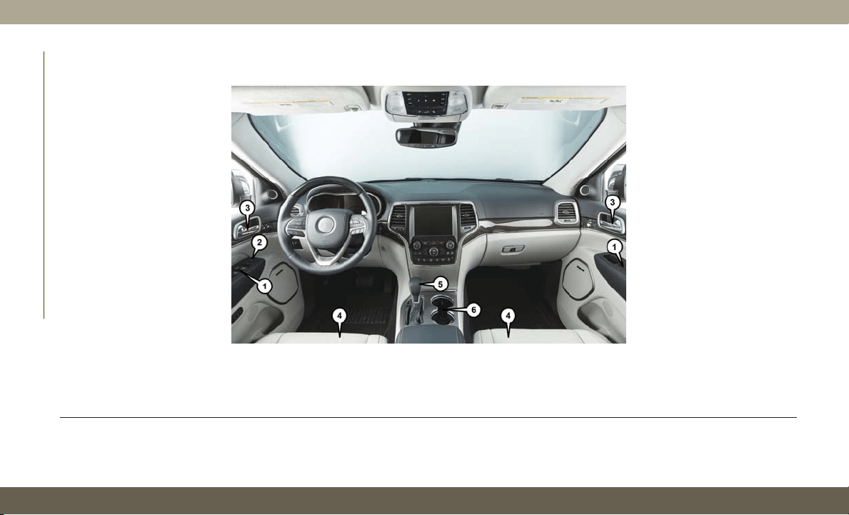
INTERIOR
Interior Features
1 — Window Switches 4 — Seats
2 — Power Mirror Switches 5 — Gear Selector
3 — Door Handles 6 — Cupholders
GRAPHICAL TABLE OF CONTENTS
12
KEYS
Key Fob
Y
our vehicle uses a keyless ignition system.
The ignition system consists of a key fob with
Remote Keyless Entry (RKE) and a START/
STOP push button ignition system. The Re-
mote Keyless Entry system consists of a key fob
and Keyless Enter-N-Go feature if equipped.
NOTE:
The key fob may not be found if it is located
next to a mobile phone, laptop or other elec-
tronic device; these devices may block the
key fob’s wireless signal.
The key fob allows you to lock or unlock the
doors and liftgate from distances up to ap-
proximately 66 ft (20 m) using a handheld
key fob. The key fob does not need to be
pointed at the vehicle to activate the system.
NOTE:
• With ignition on/start and the vehicle mov-
ing at 5 mph (8 km/h), all RKE commands
are disabled.
In case the ignition switch does not change
with the push of a button, the key fob may
have a low or fully depleted battery. A low key
fob battery can be verified by referring to the
instrument cluster, which will display direc-
tions to follow.
To Unlock The Doors And Liftgate
Push and release the unlock button on the
key fob once to unlock the driver's door or
twice within five seconds to unlock all doors
and the liftgate.
All doors can be programmed to unlock on the
first push of the unlock button. Refer to
“Uconnect Settings” in “Multimedia” in the
Owner’s Manual for further information.
NOTE:
If the vehicle is unlocked by a key fob, and no
door is opened within 60 seconds, the vehicle
will re-lock and if equipped, the security
alarm will arm.
To Lock The Doors And Liftgate
Push and release the lock button on the key
fob to lock all doors and liftgate.
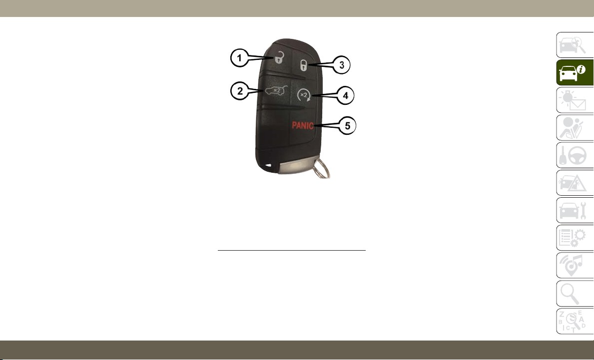
Key Fob
1 — Unlock
2 — Liftgate
3 — Lock
4 — Remote Start
5 — Panic
13

If one or more doors are open, or the liftgate
is open, the doors will lock. The doors will
unlock again automatically if the key is left
inside the passenger compartment, other-
wise the doors will stay locked.
Request For Additional Key Fobs
NOTE:
Only key fobs that are programmed to the
vehicle electronics can be used to start and
operate the vehicle. Once a key fob is pro-
grammed to a vehicle, it cannot be pro-
grammed to any other vehicle.
WARNING!
• Always remove the key fobs from the
vehicle and lock all doors when leaving
the vehicle unattended.
• Always remember to place the ignition in
the OFF mode.
Duplication of key fobs may be performed at
an authorized dealer. This procedure consists
of programming a blank key fob to the vehicle
electronics. A blank key fob is one that has
never been programmed.
NOTE:
• When having the Sentry Key Immobilizer
System serviced, bring all vehicle keys with
you to an authorized dealer.
• Keys must be ordered to the correct key cut
to match the vehicle locks.
NOTE:
Black Keys (6.4L) must be replaced with
Black Keys and Red Keys (6.2L) must be
replaced with Red Keys.
General Information
The following regulatory statement applies to
all radio frequency (RF) devices equipped in
this vehicle:
This device complies with Part 15 of the FCC
Rules and with Industry Canada license-
exempt RSS standard(s). Operation is sub-
ject to the following two conditions:
1. This device may not cause harmful inter-
ference, and
2. This device must accept any interference
received, including interference that may
cause undesired operation.
NOTE:
Changes or modifications not expressly ap-
proved by the party responsible for compli-
ance could void the user’s authority to oper-
ate the equipment.
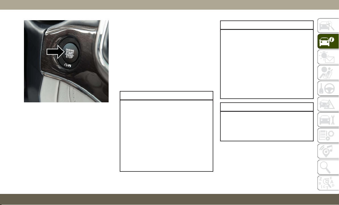
IGNITION SWITCH
Keyless Enter-N-Go — Ignition
This feature allows the driver to operate the
ignition switch with the push of a button as
long as the key fob is in the passenger com-
partment.
The Keyless Push Button Ignition has several
operating modes that are labeled and will
illuminate when in position. These modes are
OFF, ACC, RUN, and START.
NOTE:
If the ignition switch does not change with
the push of a button, the key fob may have a
low or dead battery. In this situation, a back
up method can be used to operate the igni-
tion switch. Put the nose side (side opposite
of the emergency key) of the key fob against
the ENGINE START/STOP button and push to
operate the ignition switch.
GETTING TO KNOW YOUR VEHICLE
14
The push button ignition can be placed in the
following modes:
OFF
• The engine is stopped.
• Some electrical devices (e.g. Central lock-
ing, alarm, etc.) are still available.
ACC
• Engine is not started.
• Some electrical devices are available.
RUN
• Driving position.
• All the electrical devices are available.
START
• The engine will start.
WARNING!
• When exiting the vehicle, always remove
the key fob from the vehicle and lock
your vehicle.
• Never leave children alone in a vehicle,
or with access to an unlocked vehicle.
• Allowing children to be in a vehicle un-
attended is dangerous for a number of
reasons. A child or others could be seri-
ously or fatally injured. Children should
be warned not to touch the parking
brake, brake pedal or the gear selector.
WARNING!
• Do not leave the key fob in or near the
vehicle, or in a location accessible to
children, and do not leave the ignition of
a vehicle equipped with Keyless Enter-
N-Go in the ON/RUN mode. A child
could operate power windows, other con-
trols, or move the vehicle.
• Do not leave children or animals inside
parked vehicles in hot weather. Interior
heat build-up may cause serious injury
or death.
CAUTION!
An unlocked vehicle is an invitation for
thieves. Always remove key fob from the
vehicle and lock all doors when leaving the
vehicle unattended.
NOTE:
Refer to "Starting The Engine," in "Starting
And Operating" in the Owners Manual for
further information.
START/STOP Ignition Button
15

REMOTE STARTING
SYSTEM — IF EQUIPPED
•
Push the remote start button on the key fob
twice within five seconds. Pushing the remote
start button a third time shuts the engine off.
• With remote start, the engine will only run
for 15 minutes (time out) unless the igni-
tion is placed in the ON/RUN position.
• The vehicle must be manually started with
a push of the ignition START/STOP button
after two consecutive time outs.
WARNING!
• Do not start or run an engine in a closed
garage or confined area. Exhaust gas
contains Carbon Monoxide (CO) which
is odorless and colorless. Carbon Mon-
oxide is poisonous and can cause seri-
ous injury or death when inhaled.
• Keep key fobs away from children. Op-
eration of the Remote Start System,
windows, door locks or other controls
could cause serious injury or death.
How To Use Remote Start
• Push Remote Start button on the key fob
twice within five seconds. Pushing the Re-
mote Start button a third time shuts the
engine off.
• With remote start, the engine will only run
for 15 minutes (time out) unless the igni-
tion is placed in the ON/RUN position.
• The vehicle must be manually started with
a push of the ignition START/STOP button
after two consecutive time outs.
All of the following conditions must be met
before the engine will remote start:
• Gear Selector in PARK
• Doors closed
• Hood closed
• Liftgate closed
• Hazard switch off
• Brake switch inactive (brake pedal not
pushed)
• Battery at an acceptable charge level
• PANIC button not pushed
• System not disabled from previous remote
start event
• Vehicle alarm system indicator flashing
• Ignition in STOP/OFF position
• Fuel level meets minimum requirement
WARNING!
• Do not start or run an engine in a closed
garage or confined area. Exhaust gas
contains Carbon Monoxide (CO) which
is odorless and colorless. Carbon Mon-
oxide is poisonous and can cause seri-
ous injury or death when inhaled.
• Keep key fobs away from children. Op-
eration of the Remote Start System,
windows, door locks or other controls
could cause serious injury or death.
GETTING TO KNOW YOUR VEHICLE
16

To Enter Remote Start Mode
Push and release the Remote Start button on
the key fob twice within five seconds. The
vehicle doors will lock, the turn signals will
flash twice, and the horn will chirp twice.
Then the engine will start, and the vehicle
will remain in the Remote Start mode for a
15-minute cycle.
NOTE:
• If an engine fault is present or fuel level is
low, the vehicle will start and then shut
down in 10 seconds.
• The park lamps will turn on and remain on
during Remote Start mode.
• For security, power window operation is
disabled when the vehicle is in the Remote
Start mode.
• The engine can be started two consecutive
times (two 15-minute cycles) with the key
fob. However, the ignition must be placed
in the ON/RUN position before you can
repeat the start sequence for a third cycle.
General Information
The following regulatory statement applies to
all radio frequency (RF) devices equipped in
this vehicle:
This device complies with Part 15 of the FCC
Rules and with Industry Canada license-
exempt RSS standard(s). Operation is sub-
ject to the following two conditions:
1. This device may not cause harmful inter-
ference, and
2. This device must accept any interference
received, including interference that may
cause undesired operation.
NOTE:
Changes or modifications not expressly ap-
proved by the party responsible for compli-
ance could void the user’s authority to oper-
ate the equipment.
VEHICLE SECURITY ALARM
— IF EQUIPPED
The vehicle security alarm monitors the vehicle
doors, hood, liftgate, and the Keyless Enter-
N-Go — Ignition for unauthorized operation.
While the vehicle security alarm is armed,
interior switches for door locks and liftgate
release are disabled. If something triggers the
alarm, the vehicle security alarm will provide
the following audible and visible signals:
• The horn will pulse.
• The turn signals will flash.
• The vehicle security light in the instrument
cluster will flash.
To Arm The System
Follow these steps to arm the vehicle security
alarm:
1. Make sure the vehicle’s ignition is placed
in the “OFF” mode.
• For vehicles equipped with Keyless En-
try, make sure the vehicle’s keyless
ignition system is OFF.
17

2. Perform one of the following methods to
lock the vehicle:
• Push the lock button on the interior
power door lock switch with the driver
and/or passenger door open.
• Push the lock button on the exterior
Passive Entry Door Handle with a valid
key fob available in the same exterior
zone. Refer to "Doors" in "Getting To
Know Your Vehicle" in your Owner’s
Manual for further information.
• Push the lock button on the key fob.
3. If any doors are open, close them.
To Disarm The System
The vehicle security alarm can be disarmed
using any of the following methods:
• Push the unlock button on the key fob.
• Grasp the passive entry door handle to
unlock the door, refer to "Doors" in "Getting
To Know Your Vehicle" in your Owner’s
Manual for further information.
• Cycle the ignition out of the off mode to
disarm the system.
NOTE:
• The driver's door key cylinder and the lift-
gate button on the key fob cannot arm or
disarm the vehicle security alarm.
• The vehicle security alarm remains armed
during power liftgate entry. Pushing the
liftgate button will not disarm the vehicle
security alarm. If someone enters the ve-
hicle through the liftgate and opens any
door, the alarm will sound.
• When the vehicle security alarm is armed,
the interior power door lock switches will
not unlock the doors.
The vehicle security alarm is designed to
protect your vehicle. However, you can create
conditions where the system will give you a
false alarm. If one of the previously described
arming sequences has occurred, the vehicle
security alarm will arm, regardless of whether
you are in the vehicle or not. If you remain in
the vehicle and open a door, the alarm will
sound. If this occurs, disarm the vehicle
security alarm.
If the vehicle security alarm is armed and the
battery becomes disconnected, the vehicle
security alarm will remain armed when the
battery is reconnected; the exterior lights will
flash, and the horn will sound. If this occurs,
disarm the vehicle security alarm.
Tamper Alert
If something has triggered the vehicle security
alarm in your absence, the horn will sound
three times and the exterior lights will blink
three times when you disarm the vehicle secu-
rity alarm. Check the vehicle for tampering.
DOORS
Keyless Enter-N-Go — Passive Entry
The Passive Entry system is an enhancement
to the vehicle’s key fob and a feature of
Keyless Enter-N-Go — Passive Entry. This
feature allows you to lock and unlock the
vehicle’s door(s) and fuel door without having
to push the key fob lock or unlock buttons.
NOTE:
• Passive Entry may be programmed ON/
OFF; refer to “Uconnect Settings” in “Mul-
timedia” in the Owner’s Manual for further
information.
GETTING TO KNOW YOUR VEHICLE
18
• The key fob may not be able to be detected
by the vehicle passive entry system if it is
located next to a mobile phone, laptop, or
other electronic device; these devices may
block the key fob’s wireless signal and pre-
vent the passive entry system from locking/
unlocking the vehicle.
• Passive Entry Unlock initiates illuminated
approach (Low Beams, License Plate
Lamp, Position Lamps) for whichever time
duration is set between 0, 30 (default),
60 or 90 seconds. Passive Entry Unlock
also initiates two flashes of the turn signal
lamps.
• If wearing gloves on your hands, or if it has
been raining/snowing on the Passive Entry
door handle, the unlock sensitivity can be
affected, resulting in a slower response
time.
• If the vehicle is unlocked by Passive Entry
and no door is opened within 60 seconds,
the vehicle will re-lock and if equipped will
arm the security alarm.
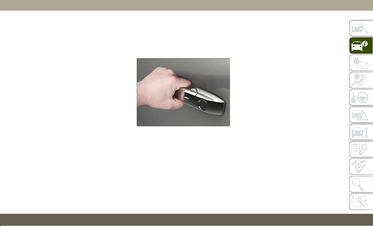
To Unlock From The Driver Side
With a valid Passive Entry key fob within 5 ft
(1.5 m) of the driver's door handle, grab the
front driver door handle to unlock the driver's
door automatically.
NOTE:
If
“Unlock All Doors 1st Press” is programmed
all doors will unlock when you grab hold of the
front driver’s door handle. To select between
“Unlock Driver Door 1st Push” and “Unlock All
Doors 1st Press,” refer to “Uconnect Settings”
in “Multimedia” in the Owner’s Manual for
further information.
To Unlock From The Passenger Side
With a valid Passive Entry key fob within 5 ft
(1.5 m) of the passenger door handle, grab
the front passenger door handle to unlock all
four doors and the liftgate automatically.
NOTE:
All doors will unlock when the front passen-
ger door handle is grabbed regardless of
the driver’s door unlock preference setting
(“Unlock Driver Door 1st Press” or “Unlock
All Doors 1st Press”).
Preventing Inadvertent Locking Of Passive Entry
Key Fob In Vehicle (FOBIK-Safe)
To minimize the possibility of unintentionally
locking a Passive Entry key fob inside your
vehicle, the Passive Entry system is equipped
with an automatic door unlock feature which
will function if the ignition switch is in the
OFF position.
Grab The Door Handle To Unlock
19
FOBIK-Safe only executes in vehicles with
passive entry. There are five situations that
trigger a FOBIK-Safe search in any passive
entry vehicle:
• A lock request is made by a valid Passive
Entry key fob while a door is open.
• A lock request is made by the Passive Entry
door handle while a door is open.
• A lock request is made by the door panel
switch while the door is open.
• When the vehicle security alarm is in pre-
arm or armed status and the liftgate transi-
tions from open to closed.
• When the liftgate transitions from opened
to closed and remote start is active.
When any of these situations occur, after all
open doors are shut, the FOBIK-Safe search
will be executed. If it finds a Passive Entry
key fob inside the car, the car will unlock and
alert the customer.
NOTE:
The vehicle will only unlock the doors when a
valid Passive Entry key fob is detected inside
the vehicle. The vehicle will not unlock the
doors when any of the following conditions
are true:
• The doors are manually locked using the
door lock knobs.
• Three attempts are made to lock the doors
using the door panel switch and then close
the doors.
• There is a valid Passive Entry key fob out-
side the vehicle within 5 ft. (1.5 m) of a
Passive Entry door handle.
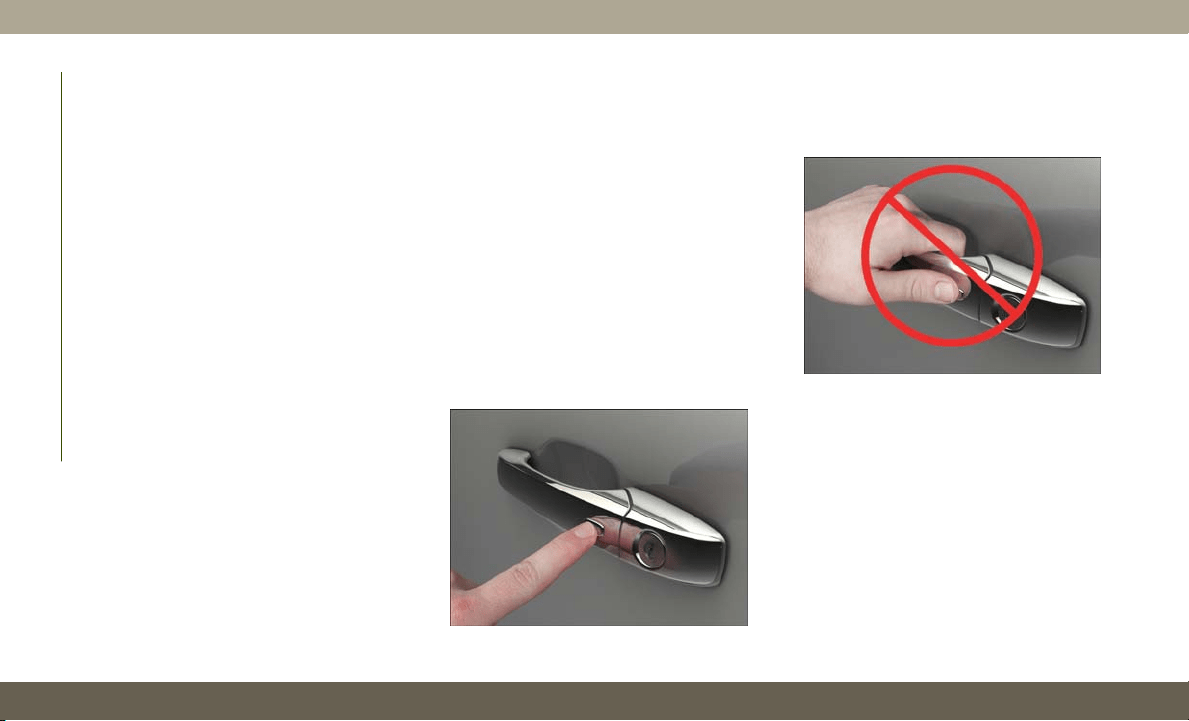
To Lock The Vehicle’s Doors And Liftgate
With one of the vehicle’s Passive Entry key fob
within 5 ft (1.5 m) of the driver or passenger
front door handles, pushing the passive entry
lock button will lock the vehicle.
NOTE:
DO NOT grab the door handle, when pushing
the door handle lock button. This could un-
lock the door(s).
NOTE:
• After pushing the door handle button, you
must wait two seconds before you can lock
or unlock the doors, using either Passive
Entry door handle. This is done to allow you
to check if the vehicle is locked by pulling
the door handle without the vehicle react-
ing and unlocking.
Push The Door Handle Button To Lock
DO NOT Grab The Door Handle When Locking
GETTING TO KNOW YOUR VEHICLE
20
• If Passive Entry is disabled using Uconnect
System, the key protection described in
"Preventing Inadvertent Locking of Passive
Entry Key Fob in Vehicle" remains active/
functional.
• The Passive Entry system will not operate if
the key fob battery is dead.
The vehicle doors can also be locked by using
the lock button located on the vehicle’s inte-
rior door panel.
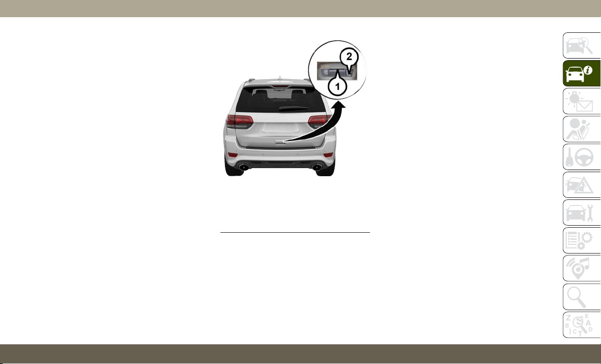
To Unlock/Enter The Liftgate
The liftgate passive entry unlock feature is
built into the electronic liftgate release. With
a valid Passive Entry key fob within 5 ft
(1.5 m) of the liftgate, push the electronic
liftgate release to open with one fluid motion.
To Lock The Liftgate
With a valid Passive Entry key fob within 5 ft
(1.5 m) of the liftgate, push the passive entry
lock button located on the outside liftgate
door handle.
NOTE:
The liftgate passive entry lock button will lock
all doors and the liftgate. The liftgate unlock
feature is built into the electronic liftgate
release.
General Information
The following regulatory statement applies to
all radio frequency (RF) devices equipped in
this vehicle:
This device complies with Part 15 of the FCC
Rules and with Industry Canada license-
exempt RSS standard(s). Operation is sub-
ject to the following two conditions:
1. This device may not cause harmful inter-
ference, and
2. This device must accept any interference
received, including interference that may
cause undesired operation.
NOTE:
Changes or modifications not expressly ap-
proved by the party responsible for compli-
ance could void the user’s authority to oper-
ate the equipment.
Electronic Liftgate Release/Liftgate
Passive Entry Location
1 — Electronic Liftgate Release
2 — Lock Button Location
21
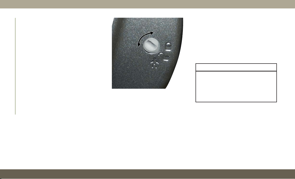
Child-Protection Door Lock System —
Rear Doors
To provide a safer environment for small chil-
dren riding in the rear seats, the rear doors
are equipped with a Child-Protection Door
Lock system.
To use the system, open each rear door, use a
flat blade screwdriver (or emergency key) and
rotate the dial to the lock or unlock position.
When the system on a door is engaged, that
door can only be opened by using the outside
door handle even if the inside door lock is in
the unlocked position.
NOTE:
• When the child lock system is engaged, the
door can be opened only by using the out-
side door handle even though the inside
door lock is in the unlocked position.
•
After disengaging the Child-Protection Door
Lock system, always test the door from the
inside to make certain it is in the desired
position.
• After engaging the Child-Protection Door
Lock system, always test the door from the
inside to make certain it is in the desired
position.
• For emergency exit with the system en-
gaged, pull up on the door lock knob (un-
locked position), roll down the window, and
open the door with the outside door handle.
WARNING!
Avoid trapping anyone in a vehicle in a
collision. Remember that the rear doors
can only be opened from the outside when
the Child-Protection locks are engaged
(locked).
NOTE:
Always use this device when carrying chil-
dren. After engaging the child lock on both
rear doors, check for effective engagement by
trying to open a door with the internal handle.
Once the Child-Protection Door Lock system
is engaged, it is impossible to open the doors
from inside the vehicle. Before getting out of
the car, be sure to check that there is no one
left inside.
Child-Protection Door Lock Function
GETTING TO KNOW YOUR VEHICLE
22
SEATS
Seats are a part of the Occupant Restraint
System of the vehicle.
WARNING!
• It is dangerous to ride in a cargo area,
inside or outside of a vehicle. In a colli-
sion, people riding in these areas are
more likely to be seriously injured or
killed.
• Do not allow people to ride in any area of
your vehicle that is not equipped with
seats and seat belts. In a collision,
people riding in these areas are more
likely to be seriously injured or killed.
• Be sure everyone in your vehicle is in a
seat and using a seat belt properly.
Driver Memory Seat — If Equipped
This feature allows the driver to store up to two
different memory profiles for easy recall
through a memory switch. Each memory profile
contains desired position settings for the driver
seat, side mirrors, and power tilt and telescopic
steering column (if equipped) and a set of
desired radio station presets. Your key fob can
also be programmed to recall the same posi-
tions when the unlock button is pushed.
NOTE:
Your vehicle is equipped with two key fobs,
one key fob can be linked to memory position
1 and the other key fob can be linked to
memory position 2.
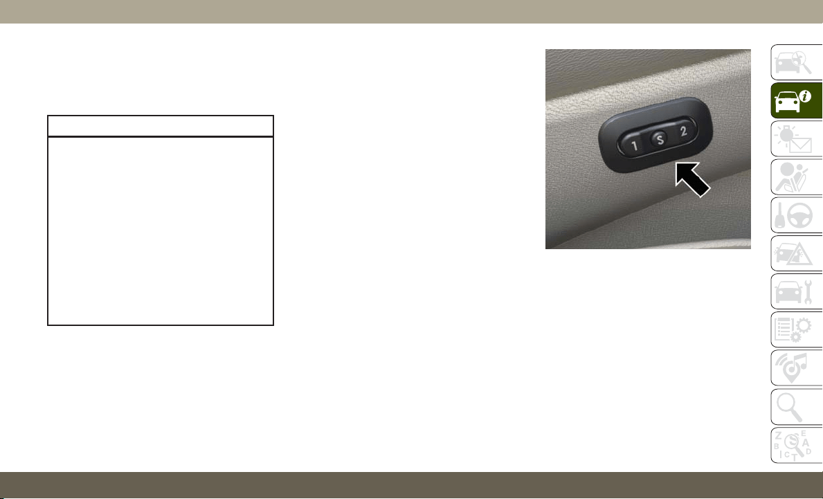
The memory seat switch is located on the
driver’s door trim panel. The switch consists
of three buttons:
• The set (S) button, which is used to activate
the memory save function.
•T
he (1) and (2) buttons which are used to
recall either of two pre-programmed memory
profiles.
Programming The Memory Feature
NOTE:
To create a new memory profile, perform the
following:
1.
Cycle the vehicle’s ignition to the ON/RUN
position (do not start the engine).
2. Adjust all memory profile settings to de-
sired preferences (i.e., seat, side mirror,
power tilt and telescopic steering column
[if equipped], and radio station presets).
Memory Seat Buttons
23

3. Push and release the set (S) button on the
memory switch.
4. Within five seconds, push and release
either of the memory buttons (1) or (2).
The instrument cluster display will dis-
play which memory position has been set.
NOTE:
• Memory profiles can be set without the
vehicle in PARK, but the vehicle must be in
PARK to recall a memory profile.
• To set a memory profile to your key fob,
refer to “Linking And Unlinking The Re-
mote Keyless Entry Key Fob To Memory” in
this section.
Linking And Unlinking The Remote Keyless
Entry Key Fob To Memory
Your key fobs can be programmed to recall
one of two pre-programmed memory profiles
by pushing the unlock button on the key fob.
NOTE:
Before programming your key fobs you must
select the “Memory Linked To Fob” feature
through the Uconnect system screen.
Refer to “Uconnect Settings” in “Multime-
dia” in your Owner’s Manual for further infor-
mation.
To program your key fobs, perform the follow-
ing:
1. Cycle the vehicle’s ignition to the OFF
position.
2. Select a desired memory profile, 1 or 2.
NOTE:
If a memory profile has not already been
set, refer to "Programming The Memory
Feature" in this section for instructions on
how to set a memory profile.
3. Once the profile has been recalled, push
and release the set (S) button on the
memory switch.
4. Within five seconds, push and release
button (1) or (2) accordingly. “Memory
Profile Set” (1 or 2) will display in the
instrument cluster.
5. Push and release the lock button on the
key fob within 10 seconds.
NOTE:
Your key fobs can be unlinked to your memory
settings by pushing the set (S) button, and
within 10 seconds, followed by pushing the
unlock button on the key fob.
Memory Position Recall
NOTE:
T
he vehicle must be in PARK to recall memory
positions. If a recall is attempted when the
vehicle is not in PARK, a message will be
displayed in the instrument cluster display.
Driver One Memory Position Recall
• To recall the memory settings for driver one
using the memory switch, push memory
button (1) on the memory switch.
• To recall the memory settings for driver one
using the key fob, push the unlock button
on the key fob linked to memory position 1.
Driver Two Memory Position Recall
• To recall the memory setting for driver two
using the memory switch, push memory
button (2) on the memory switch.
GETTING TO KNOW YOUR VEHICLE
24

• To recall the memory settings for driver two
using the key fob, push the unlock button
on the key fob linked to memory position 2.
A recall can be canceled by pushing any of
the memory buttons during a recall (S, 1, or
2), or by pushing any of the seat adjustment
switches. When a recall is canceled, the driv-
er's seat and steering column (if equipped)
stop moving. A delay of one second will occur
before another recall can be selected.
Easy Entry/Exit Seat
This feature provides automatic driver seat
positioning to enhance driver mobility when
entering and exiting the vehicle.
The distance the driver seat moves depends
on where you have the driver seat positioned
when you cycle the vehicle’s ignition to the
OFF position.
• When you cycle the vehicle’s ignition to the
OFF position, the driver seat will move
about 2.4 inches (60 mm) rearward if the
driver seat position is greater than or equal
to 2.7 inches (67.7 mm) forward of the rear
stop. The seat will return to its previously
set position when you cycle the vehicle’s
ignition to the ACC or RUN position.
• The Easy Entry/Easy Exit feature is disabled
when the driver seat position is less than
0.9 of an inch (22.7 mm) forward of the
rear stop. At this position, there is no ben-
efit to the driver by moving the seat for Easy
Exit or Easy Entry.
Each stored memory setting will have an
associated Easy Entry and Easy Exit position.
NOTE:
The Easy Entry/Exit feature is not enabled
when the vehicle is delivered from the fac-
tory. The Easy Entry/Exit feature is enabled
(or later disabled) through the programmable
features in the Uconnect system. Refer to
“Uconnect Settings” in “Multimedia” in your
Owner’s Manual for further details.
Heated Seats
On some models, the front and rear seats may
be equipped with heaters located in the seat
cushions and seat backs.
WARNING!
• Persons who are unable to feel pain to
the skin because of advanced age,
chronic illness, diabetes, spinal cord in-
jury, medication, alcohol use, exhaus-
tion or other physical condition must
exercise care when using the seat
heater. It may cause burns even at low
temperatures, especially if used for long
periods of time.
•
Do not place anything on the seat or
seatback that insulates against heat, such
as a blanket or cushion. This may cause
the seat heater to overheat. Sitting in a
seat that has been overheated could
cause serious burns due to the increased
surface temperature of the seat.
25
Front Heated Seats
The front heated seat control buttons are
located within the climate or controls screen
of the touchscreen.
You can choose from HI, LO, or OFF heat
settings. The indicator arrows in touchscreen
buttons indicate the level of heat in use. Two
indicator arrows will illuminate for HI, and
one for LO. Turning the heating elements off
will return the user to the radio screen.
• Press the heated seat button
once to
turn the HI setting on.
• Press the heated seat button
a second
time to turn the LO setting on.
• Press the heated seat button
a third
time to turn the heating elements off.
NOTE:
• Once a heat setting is selected, heat will be
felt within two to five minutes.
• The engine must be running for the heated
seats to operate.
• The level of heat selected will stay on until
the operator changes it.
Vehicles Equipped With Remote Start
On models that are equipped with remote
start, the heated seats can be programmed to
come on during a remote start.
T
his feature can be programmed through the
Uconnect system. Refer to “Uconnect Set-
tings” in “Multimedia” in your Owner’s Manual
for further details.
WARNING!
• Persons who are unable to feel pain to
the skin because of advanced age,
chronic illness, diabetes, spinal cord in-
jury, medication, alcohol use, exhaus-
tion or other physical condition must
exercise care when using the seat
heater. It may cause burns even at low
temperatures, especially if used for long
periods of time.
• Do not place anything on the seat or
seatback that insulates against heat,
such as a blanket or cushion. This may
cause the seat heater to overheat. Sit-
ting in a seat that has been overheated
WARNING!
could cause serious burns due to the
increased surface temperature of the
seat.
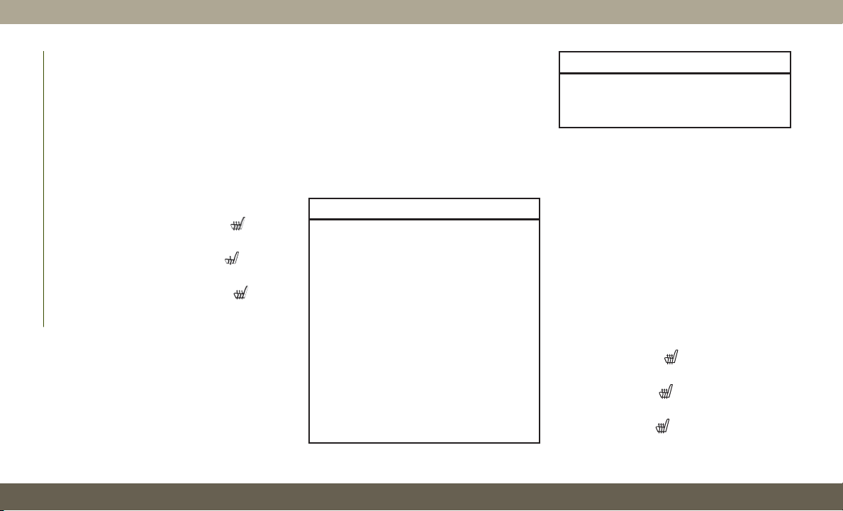
Rear Heated Seats — If Equipped
On some models, the two rear outboard seats
may be equipped with heated seats. There
are two heated seat switches that allow the
rear passengers to operate the seats indepen-
dently. The heated seat switches for each
heater are located on the rear of the center
console.
You can choose from HI, LO, or OFF heat
settings. Amber indicator lights in each
switch indicate the level of heat in use. Two
indicator lights will illuminate for HI, one for
LO and none for OFF.
• Push the switch
once to turn the HI
setting on.
• Push the switch
a second time to turn
the LO setting on.
• Push the switch
a third time to turn the
heating elements off.
GETTING TO KNOW YOUR VEHICLE
26
The level of heat selected will stay on until
the operator changes it.
WARNING!
• Persons who are unable to feel pain to
the skin because of advanced age,
chronic illness, diabetes, spinal cord in-
jury, medication, alcohol use, exhaus-
tion or other physical condition must
exercise care when using the seat
heater. It may cause burns even at low
temperatures, especially if used for long
periods of time.
• Do not place anything on the seat or
seatback that insulates against heat,
such as a blanket or cushion. This may
cause the seat heater to overheat. Sit-
ting in a seat that has been overheated
could cause serious burns due to the
increased surface temperature of the
seat.
Front Ventilated Seats
If your vehicle is equipped with ventilated
seats, the seat cushion and seat back will
have fans that draw the air from the passen-
ger compartment and move air through fine
perforations in the seat cover to help keep the
driver and front passenger cooler in higher
ambient temperatures. The fans operate at
two speeds, HI and LO.
The front ventilated seats control buttons are
located within the Uconnect system. You can
gain access to the control buttons through
the climate screen or the controls screen.
• Press the ventilated seat button
once
to choose HI.
• Press the ventilated seat button
a
second time to choose LO.
• Press the ventilated seat button
a third
time to turn the ventilated seat off.
NOTE:
The engine must be running for the ventilated
seats to operate.
Vehicles Equipped With Remote Start
On models that are equipped with remote
start, the ventilated seats can be pro-
grammed to come on during a remote start.
This feature can be programmed through the
Uconnect system. Refer to “Uconnect Set-
tings” in “Multimedia” in the Owner's Manual
for further information.
HEAD RESTRAINTS
Head restraints are designed to reduce the
risk of injury by restricting head movement in
the event of a rear-impact. Head restraints
should be adjusted so that the top of the head
restraint is located above the top of your ear.
WARNING!
• All occupants, including the driver,
should not operate a vehicle or sit in a
vehicle’s seat until the head restraints
are placed in their proper positions in
order to minimize the risk of neck injury
in the event of a crash.
27
WARNING!
• Head restraints should never be ad-
justed while the vehicle is in motion.
Driving a vehicle with the head restraints
improperly adjusted or removed could
cause serious injury or death in the event
of a collision.
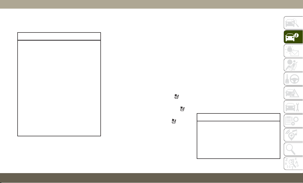
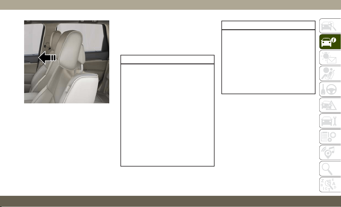
Supplemental Active Head Restraints —
Front Seats
Active Head Restraints are passive, deploy-
able components, and vehicles with this
equipment cannot be readily identified by
any markings, only through visual inspection
of the head restraint. The Active Head Re-
straints (AHR) will be split in two halves, with
the front half being soft foam and trim, the
back half being decorative plastic.
When AHRs deploy during a rear impact, the
front half of the head restraint extends for-
ward to reduce the gap between the back of
the occupant’s head and the AHR. This sys-
tem is design to reduce the risk of injury to
the driver or front passenger in certain types
of rear impacts. Refer to “Occupant Restraint
Systems” in “Safety” for further information.
To raise the head restraint, pull upward on
the head restraint. To lower the head re-
straint, push the adjustment button, located
at the base of the head restraint, and push
downward on the head restraint.
For comfort, the Active Head Restraints can
be tilted forward and rearward. To tilt the
head restraint closer to the back of your head,
pull forward on the bottom of the head re-
straint. Push rearward on the bottom of the
head restraint to move the head restraint
away from your head.
Adjustment Button
Active Head Restraint (Normal Position)
GETTING TO KNOW YOUR VEHICLE
28
NOTE:
• The head restraints should only be removed
by qualified technicians, for service pur-
poses only. If either of the head restraints
require removal, see an authorized dealer.
• In the event of deployment of an Active
Head Restraint, refer to “Occupant Re-
straint Systems/Resetting Active Head
Restraints (AHR)” in “Safety” for further
information.
WARNING!
• ALL the head restraints MUST be rein-
stalled in the vehicle to properly protect
the occupants.
• All occupants, including the driver,
should not operate a vehicle or sit in a
vehicle’s seat until the head restraints
are placed in their proper positions in
order to minimize the risk of neck injury
in the event of a collision.
• Do not place items over the top of the
Active Head Restraint, such as coats,
seat covers or portable DVD players.
These items may interfere with the op-
eration of the Active Head Restraint in
the event of a collision and could result
in serious injury or death.
WARNING!
• Active Head Restraints may be deployed
if they are struck by an object such as a
hand, foot or loose cargo. To avoid acci-
dental deployment of the Active Head
Restraint ensure that all cargo is se-
cured, as loose cargo could contact the
Active Head Restraint during sudden
stops. Failure to follow this warning
could cause personal injury if the Active
Head Restraint is deployed.
Active Head Restraint (Tilted)
29
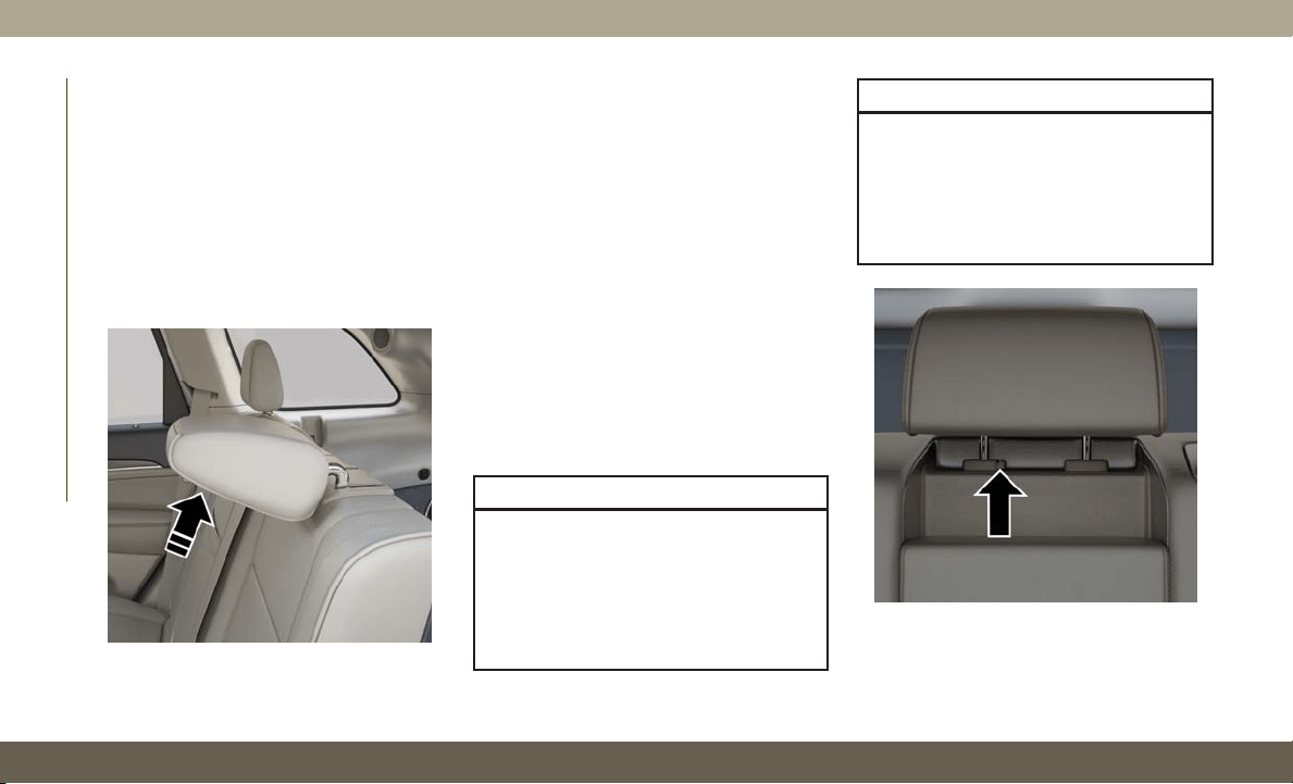
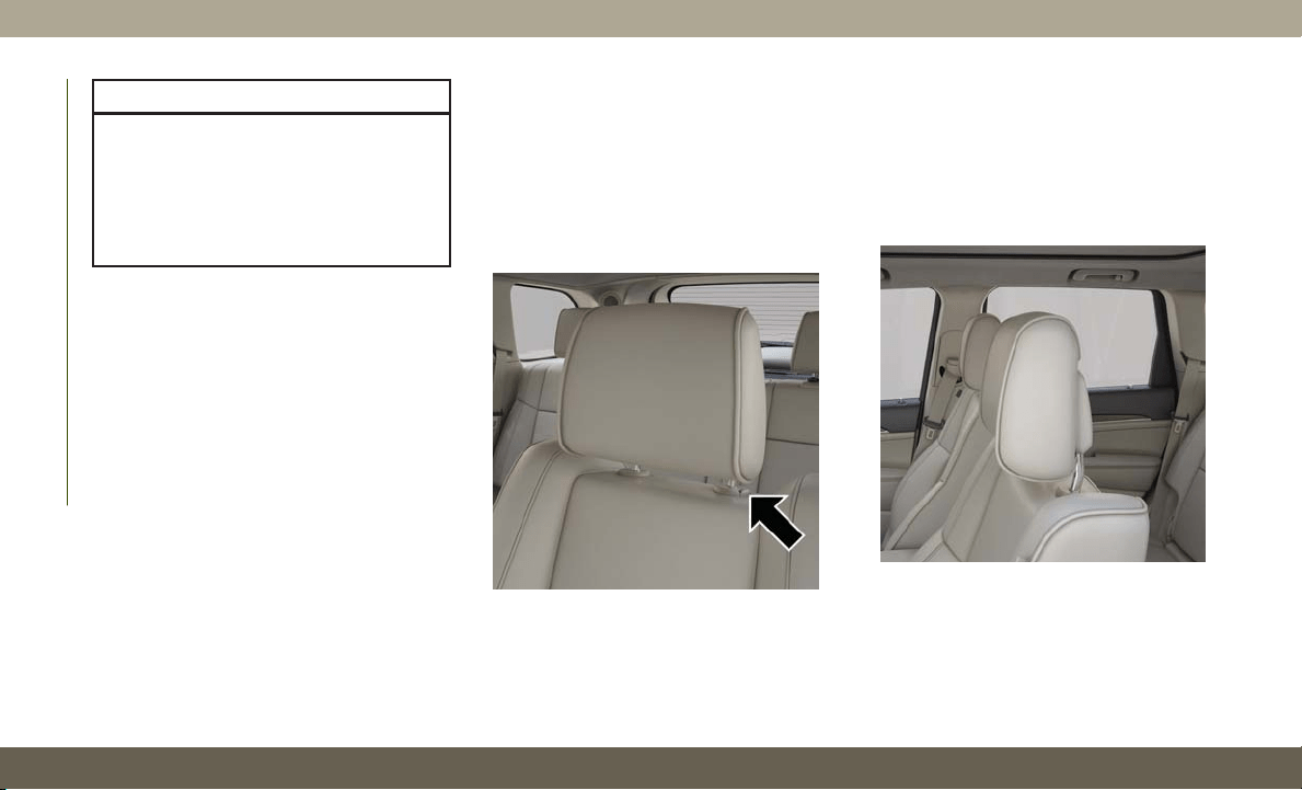
Adjustment — Rear Seats
The head restraints on the outboard seats are
not adjustable. They automatically fold for-
ward when the rear seat is folded to a load
floor position, but do not return to their nor-
mal position when the rear seat is raised.
After returning either seat to its upright posi-
tion, raise the head restraint until it locks in
place. The outboard head restraints are not
removable.
The center head restraint has limited adjust-
ment. Lift upward on the head restraint to
raise it, or push downward on the head re-
straint to lower it.
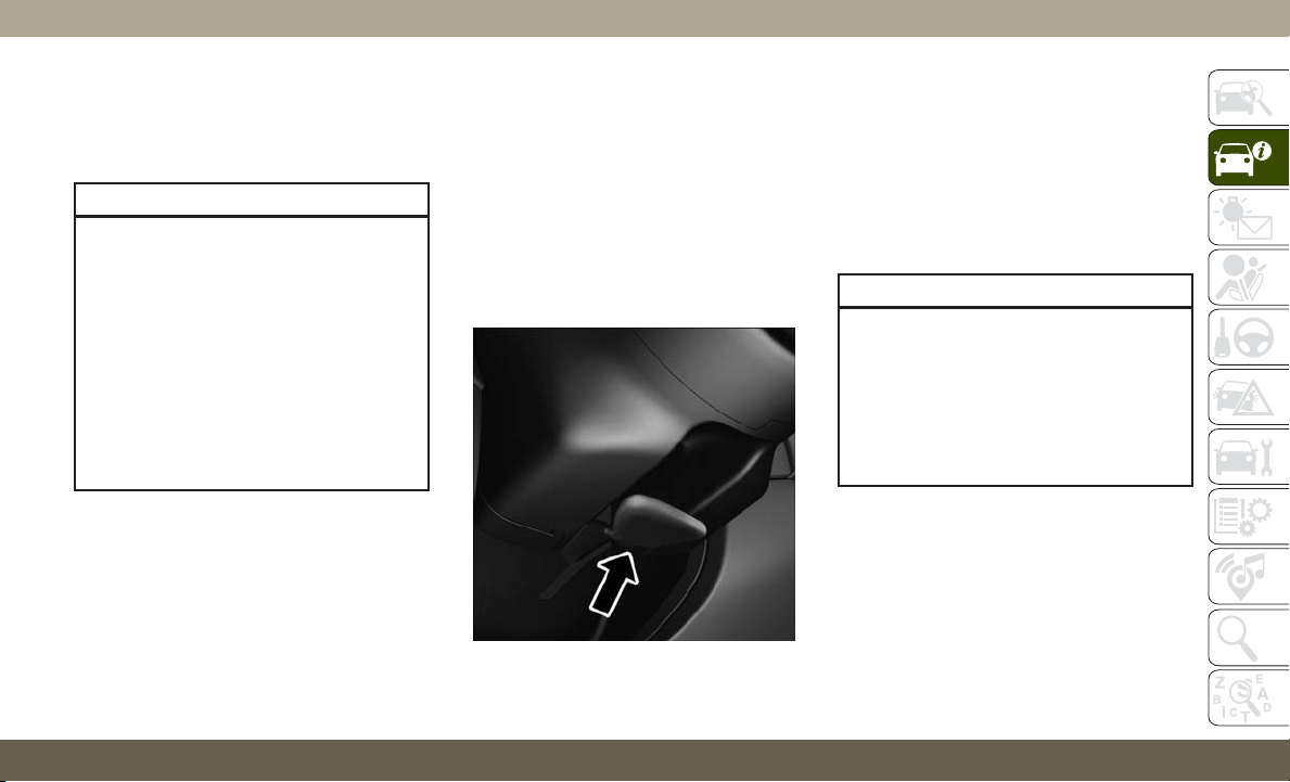
Head Restraint Removal — Rear Seats
The center head restraint can be adjusted
when occupied, or removed for Child Seat
Tethering. To remove the head restraint, raise
it as far as it can go by pulling upward. Then,
push the release button at the base of the
post while pulling the head restraint upward.
To reinstall the head restraint, put the head
restraint posts into the holes and push down-
ward. Then, adjust the head restraint to the
appropriate height.
WARNING!
• ALL the head restraints MUST be rein-
stalled in the vehicle to properly pro-
tect the occupants. Follow the re-
installation instructions above prior to
operating the vehicle or occupying a
seat.
WARNING!
• Sitting in a seat with the head restraint
in its lowered position could result in
serious injury or death in a collision.
Always make sure the outboard head
restraints are in their upright positions
when the seat is to be occupied.
Folded Rear Head Restraint
Center Head Restraint Release Button
GETTING TO KNOW YOUR VEHICLE
30
NOTE:
For proper routing of a Child Seat Tether, refer
to “Occupant Restraint Systems” in “Safety”
for further information.
WARNING!
• A loose head restraint thrown forward in
a collision or hard stop could cause se-
rious injury or death to occupants of the
vehicle. Always securely stow removed
head restraints in a location outside the
occupant compartment.
• ALL the head restraints MUST be rein-
stalled in the vehicle to properly protect
the occupants. Follow the re-installation
instructions above prior to operating the
vehicle or occupying a seat.
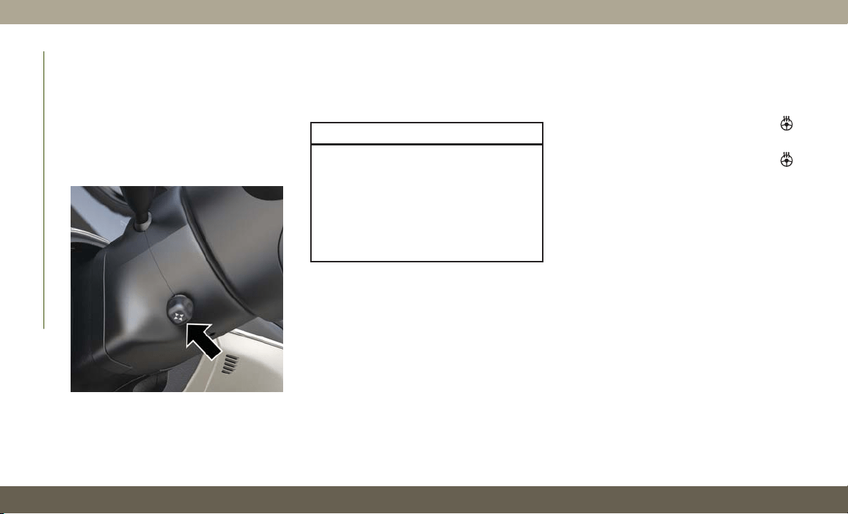
STEERING WHEEL
Manual Tilt/Telescoping Steering Column —
If Equipped
This feature allows you to tilt the steering
column upward or downward. It also allows
you to lengthen or shorten the steering col-
umn. The tilt/telescoping lever is located be-
low the steering wheel at the end of the
steering column.
To unlock the steering column, push the lever
downward (toward the floor). To tilt the steer-
ing column, move the steering wheel upward
or downward as desired. To lengthen or
shorten the steering column, pull the steering
wheel outward or push it inward as desired.
To lock the steering column in position, push
the lever upward until fully engaged.
WARNING!
Do not adjust the steering column while
driving. Adjusting the steering column
while driving or driving with the steering
column unlocked, could cause the driver
to lose control of the vehicle. Failure to
follow this warning may result in serious
injury or death.
Manual Tilt/Telescoping Steering Column
Handle
31
Power Tilt/Telescoping Steering Column —
If Equipped
This feature allows you to tilt the steering
column upward or downward. It also allows
you to lengthen or shorten the steering col-
umn. The power tilt/telescoping steering col-
umn lever is located below the multifunction
lever on the steering column.
To tilt the steering column, move the lever up
or down as desired. To lengthen or shorten
the steering column, pull the lever toward you
or push the lever away from you as desired.
WARNING!
Do not adjust the steering column while
driving. Adjusting the steering column
while driving or driving with the steering
column unlocked, could cause the driver
to lose control of the vehicle. Failure to
follow this warning may result in serious
injury or death.
Heated Steering Wheel — If Equipped
The steering wheel contains a heating ele-
ment that helps warm your hands in cold
weather. The heated steering wheel has only
one temperature setting. Once the heated
steering wheel has been turned on, it will stay
on until the operator turns it off. The heated
steering wheel may not turn on when it is
already warm.
The heated steering wheel control button is
located on the center of the instrument panel
below the touchscreen and within the climate
or controls screen of the touchscreen.
• Push the heated steering wheel button
once to turn the heating element on.
• Push the heated steering wheel button
a second time to turn the heating element
off.
NOTE:
The engine must be running for the heated
steering wheel to operate.
Vehicles Equipped With Remote Start
On models that are equipped with remote
start, the heated steering wheel can be pro-
grammed to come on during a remote start.
This feature can be programmed through the
Uconnect system. Refer to “Uconnect Set-
tings” in “Multimedia” in your Owner’s Manual
for further information.
Power Tilt/Telescoping Control
GETTING TO KNOW YOUR VEHICLE
32
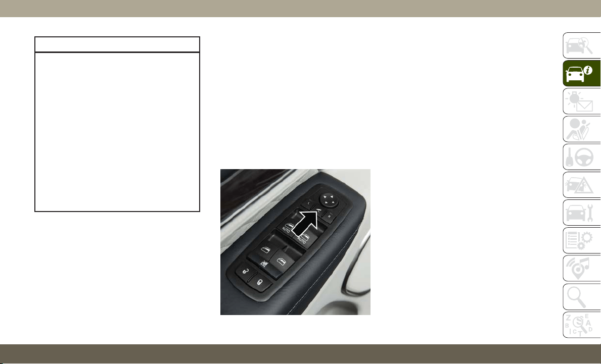
WARNING!
• Persons who are unable to feel pain to
the skin because of advanced age,
chronic illness, diabetes, spinal cord in-
jury, medication, alcohol use, exhaus-
tion, or other physical conditions must
exercise care when using the steering
wheel heater. It may cause burns even at
low temperatures, especially if used for
long periods.
• Do not place anything on the steering
wheel that insulates against heat, such
as a blanket or steering wheel covers of
any type and material. This may cause
the steering wheel heater to overheat.
MIRRORS
Power Folding Outside Mirrors —
If Equipped
If equipped with power folding mirrors, they
can be electrically folded rearward and un-
folded into the drive position.
The switch for the power folding mirrors is
located between the power mirror switches L
(left) and R (right). Push the switch once and
the mirrors will fold in, push the switch a
second time and the mirrors will return to the
normal driving position.
If the mirror is manually folded after electri-
cally cycled, a potential extra button push is
required to get the mirrors back to the home
position. If the mirror does not electrically
fold, check for ice or dirt build up at the pivot
area which can cause excessive drag.
Automatic Power Folding Mirrors
When the Automatic Fold Mirrors feature is
enabled, the exterior mirrors will fold in when
exiting the vehicle (the ignition is OFF, all
doors are closed, and the doors are locked).
•
If the exterior mirrors were auto-folded, they
will unfold when the ignition is turned ON.
• If the exterior mirrors were manually folded,
they will not automatically unfold.
NOTE:
The Automatic Fold/Unfold Mirrors feature is
not turned on when delivered from the
factory. The Automatic Fold/Unfold Mirrors
feature can be turned on and off using
the Uconnect System. Refer to “Uconnect
Settings” in “Multimedia” in your Owner’s
Manual for further information.
Resetting The Power Folding Outside Mirrors
You may need to reset the power folding
mirrors if the following occurs:
• The mirrors are accidentally blocked while
folding.
•
The mirrors are accidentally manually folded/
unfolded.
Power Folding Mirror Switch
33

• The mirrors come out of the unfolded posi-
tion.
• The mirrors shake and vibrate at normal
driving speeds.
To reset the power folding mirrors: Fold and
unfold them by pushing the button (this may
require multiple button pushes). This resets
them to their normal position.
Tilt Side Mirrors In Reverse (Available
With Memory Seat Only) — If Equipped
Tilt Side Mirrors In Reverse provides auto-
matic outside mirror positioning which will
aid the driver’s view of the ground rearward of
the front doors. Outside mirrors will move
slightly downward from the present position
when the vehicle is shifted into REVERSE.
Outside mirrors will then return to the original
position when the vehicle is shifted out of
REVERSE position. Each stored memory seat
setting will have an associated Tilt Side Mir-
rors In Reverse position.
NOTE:
The Tilt Side Mirrors In Reverse feature is not
turned on when delivered from the factory.
The Tilt Side Mirrors In Reverse feature can
be turned on and off using the Uconnect
System. Refer to “Uconnect Settings” in
“Multimedia” in the Owner’s Manual for fur-
ther information.
EXTERIOR LIGHTS
Headlight Switch
The headlight switch is located on the left
side of the instrument panel, next to the
steering wheel. The headlight switch controls
the operation of the headlights, parking
lights, instrument panel lights, cargo lights,
and fog lights (if equipped).
To turn on the headlights, rotate the head-
light switch clockwise. When the headlight
switch is on, the parking lights, taillights,
license plate light and instrument panel
Headlight Switch
1 — Auto
2 — Rotate Headlight Switch
3 — Rotate Dimmer
4 — Push Fog Lights
GETTING TO KNOW YOUR VEHICLE
34
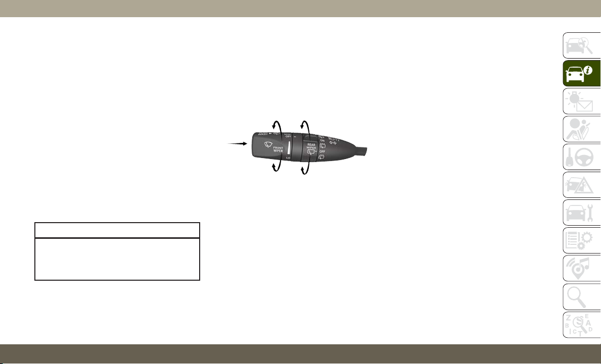
lights are also turned on. To turn off the
headlights, rotate the headlight switch back
to the O (off) position.
NOTE:
• Your vehicle is equipped with plastic head-
light and fog light (if equipped) lenses that
are lighter and less susceptible to stone
breakage than glass lights. Plastic is not as
scratch resistant as glass and therefore
different lens cleaning procedures must be
followed.
• To minimize the possibility of scratching
the lenses and reducing light output, avoid
wiping with a dry cloth. To remove road dirt,
wash with a mild soap solution followed by
rinsing.
CAUTION!
Do not use abrasive cleaning components,
solvents, steel wool or other abrasive ma-
terials to clean the lenses.
Multifunction Lever
The multifunction lever is located on the left
side of the steering column.
Daytime Running Lights — If Equipped
Non-SRT Vehicles
The Daytime Running Lights (low intensity)
come on whenever the engine is running, and
the transmission is not in the PARK position.
The lights will remain on until the ignition is
switched to the OFF or ACC position or the
parking brake is engaged.
NOTE:
• If a turn signal is activated, the DRL lamp
on the same side of the vehicle will turn off
for the duration of the turn signal activa-
tion. Once the turn signal is no longer
active, the DRL lamp will illuminate.
• The DRL function may be disabled through
the Uconnect system. Refer to “Uconnect
Settings” in “Multimedia” in the Owner’s
Manual for further information.
SRT Vehicles
The Daytime Running Lights (bright inten-
sity) come on whenever the engine is running,
and the transmission is not in the PARK
position. The lights will remain on until the
ignition is switched to the OFF or ACC posi-
tion or the parking brake is engaged.
The headlight switch must be used for normal
nighttime driving.
Multifunction Lever
35

High/Low Beam Switch
Push the multifunction lever toward the in-
strument panel to switch the headlights to
high beams. Pulling the multifunction back
toward the steering wheel will turn the low
beams back on, or shut the high beams off.
Automatic High Beam — If Equipped
The Automatic High Beam Headlamp Control
system provides increased forward lighting at
night by automating high beam control
through the use of a digital camera mounted
on the inside rearview mirror. This camera
detects vehicle specific light and automati-
cally switches from high beams to low beams
until the approaching vehicle is out of view.
NOTE:
• The Automatic High Beam Headlamp Con-
trol can be turned on or off by selecting
“ON” under “Auto High Beam” within your
Uconnect settings, as well as turning the
headlight switch to the AUTO position. Re-
fer to “Uconnect Settings” in “Multime-
dia” in the Owner’s Manual for further in-
formation.
• Broken, muddy, or obstructed headlights
and taillights of vehicles in the field of view
will cause headlights to remain on longer
(closer to the vehicle). Also, dirt, film, and
other obstructions on the windshield or
camera lens will cause the system to func-
tion improperly.
If the windshield or Automatic High Beam
Headlamp Control mirror is replaced, the
mirror must be re-aimed to ensure proper
performance. See a local authorized dealer.
Flash-To-Pass
You can signal another vehicle with your
headlights by lightly pulling the multifunc-
tion lever toward you. This will cause the high
beam headlights to turn on, and remain on,
until the lever is released.
Automatic Headlights — If Equipped
This system automatically turns the head-
lights on or off according to ambient light
levels. To turn the system on, rotate the
headlight switch to the A (auto) position.
When the system is on, the Headlight Delay
feature is also on. This means the headlights
will stay on for up to 90 seconds after you
turn the ignition switch to the OFF position.
To turn the automatic headlights off, turn the
headlight switch out of the A (auto) position.
NOTE:
The engine must be running before the head-
lights will turn on in the Automatic Mode.
Parking Lights And Panel Lights
To turn on the parking lights and instrument
panel lights, rotate the headlight switch clock-
wise. To turn off the parking lights, rotate the
headlight switch back to the O (off) position.
Headlights On Automatically With
Wipers
If your vehicle is equipped with Automatic
Headlights, it also has this customer-
programmable feature. When your headlights
are in the automatic mode and the engine is
running, they will automatically turn on when
the wiper system is on. This feature is pro-
GETTING TO KNOW YOUR VEHICLE
36

grammable through the Uconnect system
screen. Refer to “Uconnect Settings” in
“Multimedia” in the Owner’s Manual for fur-
ther information.
If your vehicle is equipped with a “Rain
Sensitive Wiper System” and it is activated,
the headlights will automatically turn on after
the wipers complete five wipe cycles within
approximately one minute, and they will turn
off approximately four minutes after the wip-
ers completely stop.
Refer to “Windshield Wipers And Washers” in
“Getting To Know Your Vehicle” for further
information.
NOTE:
When your headlights come on during the day-
time, the instrument panel lights will automati-
cally dim to the lower nighttime intensity.
Headlight Delay
To aid in your exit, your vehicle is equipped
with a headlight delay that will leave the
headlights on for approximately up to 90 sec-
onds. This delay is initiated when the ignition
is turned OFF while the headlight switch is
on, and then the headlight switch is cycled
off. Headlight delay can be cancelled by
either turning the headlight switch on then
off, or by turning the ignition ON.
NOTE:
• This feature can be programmed through
the Uconnect system. Refer to “Uconnect
Settings” in “Multimedia” in the Owner’s
Manual for further information.
• The headlight delay feature is automati-
cally activated if the headlight switch is left
in the A (auto) position when the ignition is
placed in the OFF position.
Lights-On Reminder
If the headlights, parking lights, or cargo
lights are left on after the ignition is turned
OFF, a chime will sound when the driver’s
door is opened.
Fog Lights — If Equipped
The fog lights are turned on by rotating the
headlight switch to the parking light or head-
light position and pushing in the headlight
rotary control.
The fog lights will operate only when the
parking lights are on or when the vehicle
headlights are on low beam. An indicator
light located in the instrument cluster will
illuminate when the fog lights are on. The fog
lights will turn off when the switch is pushed
a second time, when the headlight switch is
rotated to the off position, or the high beam is
selected.
Fog Light Switch
37
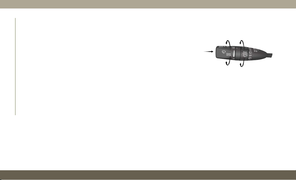
Turn Signals
Move the multifunction lever up or down and
the arrows on each side of the instrument
cluster flash to show proper operation of the
front and rear turn signal lights.
NOTE:
If either light remains on and does not flash,
or there is a very fast flash rate, check for a
defective outside light bulb. If an indicator
fails to light when the lever is moved, it would
suggest that the indicator bulb is defective.
Battery Saver
To protect the life of your vehicle’s battery,
load shedding is provided for both the interior
and exterior lights.
If the ignition is OFF and any door is left ajar
for 10 minutes or the dimmer control is
rotated all the way up to the dome on position
for 10 minutes, the interior lights will auto-
matically turn off.
NOTE:
Battery saver mode is canceled if the ignition
is ON.
If the headlights remain on while the ignition
is cycled OFF, the exterior lights will auto-
matically turn off after eight minutes. If the
headlights are turned on and left on for eight
minutes while the ignition is OFF, the exterior
lights will automatically turn off.
WINDSHIELD WIPERS AND
WASHERS
The windshield wiper/washer controls are lo-
cated on the multifunction lever on the left
side of the steering column. The front wipers
are operated by rotating a switch, located on
the end of the lever. For information on the
rear wiper/washer, refer to “Rear Window
Wiper/Washer” in this section.
Windshield Wiper Operation
Rotate the end of the lever to one of the first
four detent positions for intermittent set-
tings, the fifth detent for low wiper operation
and the sixth detent for high wiper operation.
Multifunction Lever
GETTING TO KNOW YOUR VEHICLE
38
CAUTION!
Always remove any buildup of snow that
prevents the windshield wiper blades from
returning to the “park” position. If the
windshield wiper switch is turned off, and
the blades cannot return to the “park”
position, damage to the wiper motor may
occur.
Intermittent Wiper System
Use one of the four intermittent wiper set-
tings when weather conditions make a single
wiping cycle, with a variable delay between
cycles, desirable. At driving speeds above
10 mph (16 km/h), the delay can be regu-
lated from a maximum of approximately
18 seconds between cycles (first detent), to a
cycle every one second (fourth detent).
NOTE:
If the vehicle is moving less than 10 mph
(16 km/h), delay times will be doubled.
Windshield Washer Operation
To use the washer, push on the end of the
lever (toward the steering wheel) and hold
while spray is desired. If the lever is pushed
while in the intermittent setting, the wipers
will turn on and operate for several wipe
cycles after the end of the lever is released,
and then resume the intermittent interval
previously selected.
If the end of the lever is pushed while the
wipers are in the off position, the wipers will
operate for several wipe cycles, then turn off.
NOTE:
As a protective measure, the pump will stop if
the switch is held for more than 20 seconds.
Once the switch is released the pump will
resume normal operation.
WARNING!
Sudden loss of visibility through the wind-
shield could lead to a collision. You might
not see other vehicles or other obstacles.
WARNING!
To avoid sudden icing of the windshield
during freezing weather, warm the wind-
shield with the defroster before and during
windshield washer use.
Mist
Use the Mist feature when weather condi-
tions make occasional usage of the wipers
necessary. Rotate the end of the lever down-
ward to the MIST position and release for a
single wiping cycle.
NOTE:
The Mist feature does not activate the washer
pump; therefore, no washer fluid will be
sprayed on the windshield. The wash func-
tion must be used in order to spray the
windshield with washer fluid.
39

Rain Sensing Wipers — If Equipped
This feature senses rain or snowfall on the
windshield and automatically activates the
wipers for the driver. The feature is especially
useful for road splash or overspray from the
windshield washers of the vehicle ahead.
Rotate the end of the multifunction lever to
one of four settings to activate this feature.
The sensitivity of the system can be adjusted
with the multifunction lever. Wiper delay po-
sition one is the least sensitive, and wiper
delay position four is the most sensitive.
NOTE:
Wiper delay position three should be used for
normal rain conditions.
Settings one and two can be used if the driver
desires less wiper sensitivity. Setting four can
be used if the driver desires more sensitivity.
Place the wiper switch in the OFF position
when not using the system.
NOTE:
• The Rain Sensing feature will not operate
when the wiper switch is in the low or
high-speed position.
• The Rain Sensing feature may not function
properly when ice, or dried salt water is
present on the windshield.
• Use of Rain-X or products containing wax or
silicone may reduce Rain Sensing perfor-
mance.
• The Rain Sensing feature can be turned on
and off using the Uconnect System, refer to
“Uconnect Settings” in “Multimedia” in
the Owner’s Manual for further information.
The Rain Sensing system has protection fea-
tures for the wiper blades and arms, and will
not operate under the following conditions:
• Low Ambient Temperature — When the igni-
tion is first turned ON, the Rain Sensing
system will not operate until the wiper
switch is moved, vehicle speed is greater
than 3 mph (5 km/h), or the outside tem-
perature is greater than 32°F (0°C).
• Transmission In NEUTRAL Position — When
the ignition is ON, and the automatic trans-
mission is in the NEUTRAL position, the
Rain Sensing system will not operate until
the wiper switch is moved, vehicle speed is
greater than 3 mph (5 km/h), or the gear
selector is moved out of the NEUTRAL
position.
Remote Start Mode Inhibit — On vehicles
equipped with Remote Starting system, Rain
Sensing wipers are not operational when the
vehicle is in the remote start mode. Once the
operator is in the vehicle and has placed the
ignition switch in the RUN position, rain
sensing wiper operation can resume, if it has
been selected, and no other inhibit condi-
tions (mentioned previously) exist.
GETTING TO KNOW YOUR VEHICLE
40

Rear Window Wiper/Washer
The rear wiper/washer controls are located on
the multifunction lever on the left side of the
steering column. The rear wiper/washer is
operated by rotating a switch, located at the
middle of the lever.
Rotate the center portion of the lever upward
to the first detent for intermittent operation
and to the second detent for continuous rear
wiper operation.
Rotating the center portion upward once
more will activate the washer pump which
will continue to operate as long as the switch
is held. Upon release of the switch, the wip-
ers will resume the continuous rear wiper
operation. When this rotary control is in the
OFF position, rotating it downward will acti-
vate the rear washer pump which will con-
tinue to operate as long as the switch is held.
Once the switch is released it will return to
the OFF position and the wipers will cycle
several times before returning to the parked
position.
NOTE:
As a protective measure, the pump will stop if
the switch is held for more than 20 seconds.
Once the switch is released the pump will
resume normal operation.
If the rear wiper is operating when the igni-
tion is turned OFF, the wiper will automati-
cally return to the “park” position.
CLIMATE CONTROLS
The Climate Control System allows you to
regulate the temperature, air flow, and direc-
tion of air circulating throughout the vehicle.
The controls are located on the touchscreen
(if equipped) and on the instrument panel
below the radio.
41
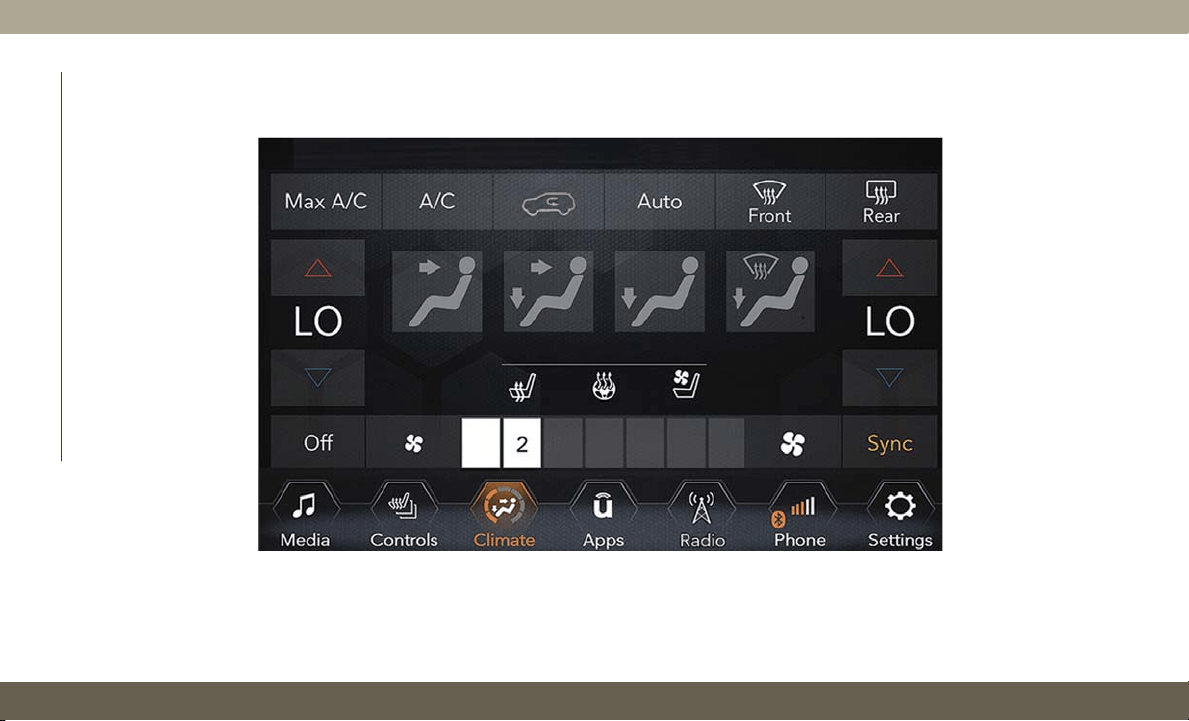
Automatic Climate Controls Overview
Uconnect 4 With 7–inch Display Automatic Climate Controls
GETTING TO KNOW YOUR VEHICLE
42
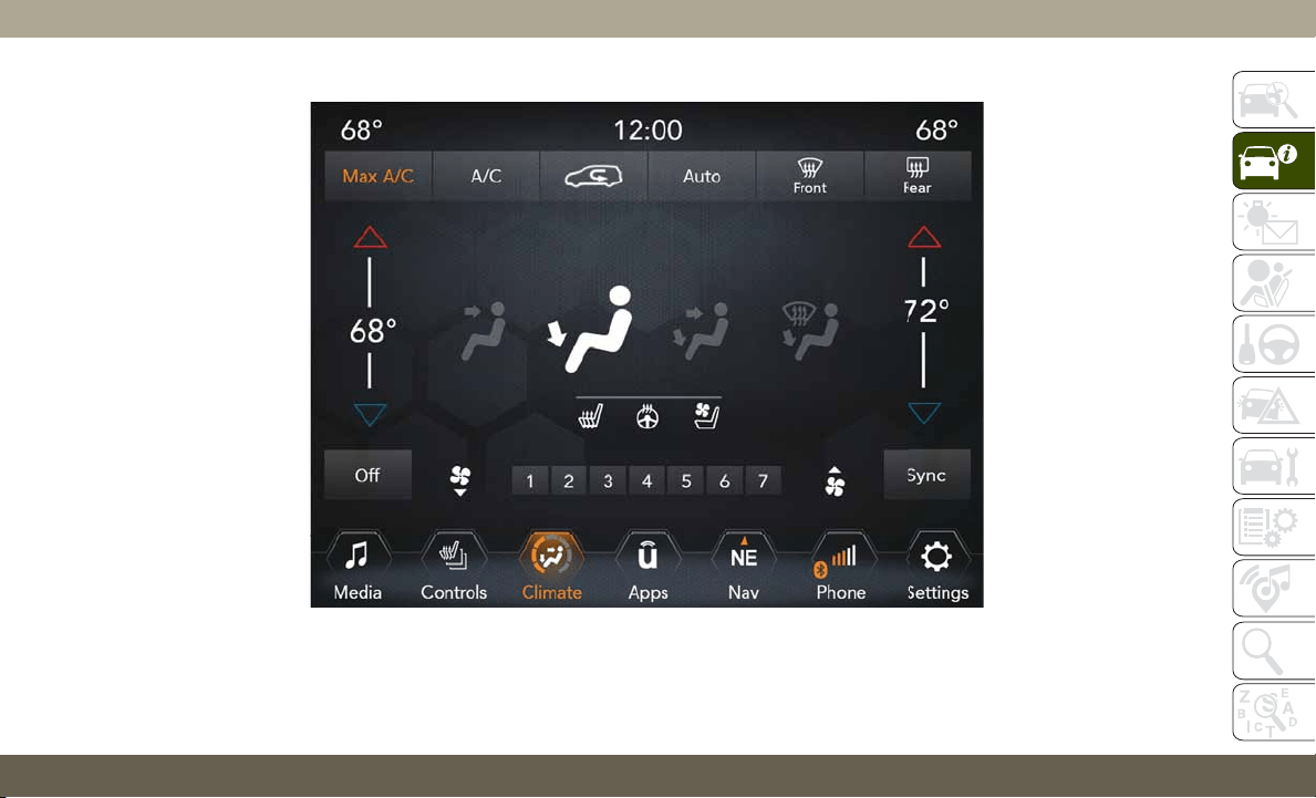
Uconnect 4C/4C NAV With 8.4–inch Display Automatic Climate Controls
43
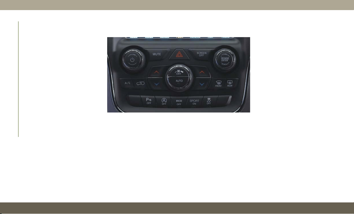
Automatic Climate Controls On The Faceplate
GETTING TO KNOW YOUR VEHICLE
44
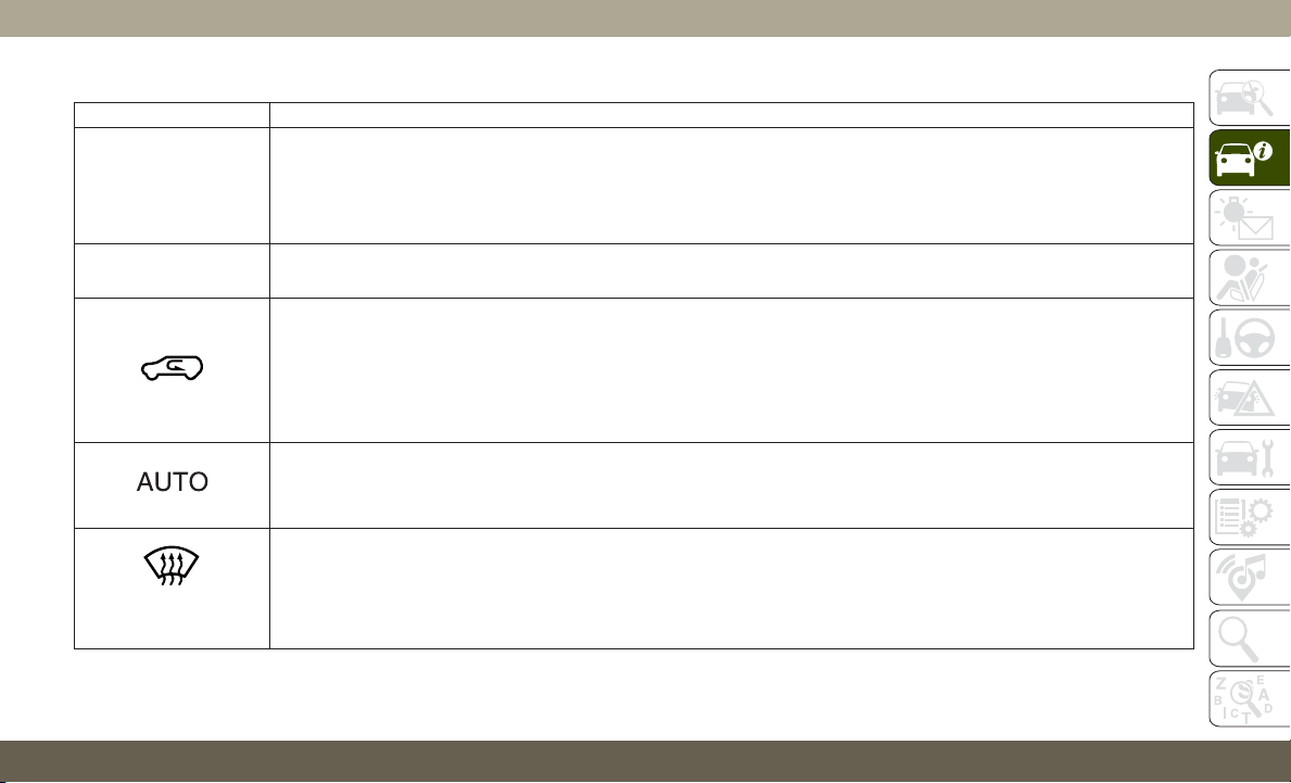
Control Descriptions
Icon Description
MAX
A/C
MAX A/C Button
Press and release to change the current setting, the indicator illuminates when MAX A/C is on. Performing this function
again will cause the MAX A/C operation to switch into manual mode and the MAX A/C indicator will turn off.
NOTE:
The MAX A/C setting is only available on the touchscreen.
A/C
A/C Button
Press and release to change the current setting. The indicator illuminates when A/C is on.
Recirculation Button
Press and release this button on the touchscreen, or push the button on the faceplate, to change the system between
recirculation mode and outside air mode. Recirculation can be used when outside conditions, such as smoke, odors,
dust, or high humidity are present. Recirculation can be used in all modes. Recirculation may be unavailable (button on
the touchscreen greyed out) if conditions exist that could create fogging on the inside of the windshield. The A/C can
be deselected manually without disturbing the mode control selection. Continuous use of the Recirculation mode may
make the inside air stuffy and window fogging may occur. Extended use of this mode is not recommended.
AUTO Button
Automatically controls the interior cabin temperature by adjusting airflow distribution and amount. Toggling this func-
tion will cause the system to switch between manual mode and automatic modes. Refer to “Automatic Operation”
within this section for more information.
FRONT
Front Defrost Button
The Front Defrost button changes the current airflow setting to Defrost mode. The indicator illuminates when this feature is
on. Air comes from the windshield and side window demist outlets. When the defrost button is selected, the blower level
may increase. Use Defrost mode with maximum temperature settings for best windshield and side window defrosting and
defogging. When toggling the front defrost mode button, the climate system will return to previous setting.
45
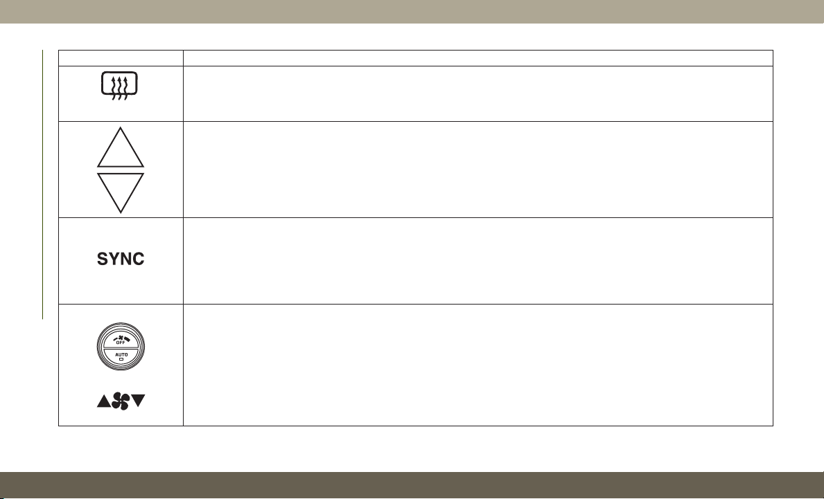
Icon Description
REAR
Rear Defrost Button
The Rear Defrost Control button turns on the rear window defroster and the heated outside mirrors (if equipped).
An indicator will illuminate when the rear window defroster is on. The rear window defroster automatically turns off after
ten minutes.
Driver And Passenger Temperature Up And Down Buttons
Provides the driver and passenger with independent temperature control. Push the red button on the faceplate or touch-
screen or press and slide the temperature bar towards the red arrow button on the touchscreen for warmer temperature
settings. Push the blue button on the faceplate or touchscreen or press and slide the temperature bar towards the blue
arrow button on the touchscreen for cooler temperature settings.
SYNC Button
Press the SYNC button on the touchscreen to toggle the SYNC feature on/off. The SYNC indicator is illuminated when
this feature is enabled. SYNC is used to synchronize the passenger temperature setting with the driver temperature set-
ting. Changing the passenger’s temperature setting while in SYNC will automatically exit this feature.
NOTE:
The SYNC setting is only available on the touchscreen.
Faceplate Knob
Touchscreen Buttons
Blower Control
Blower Control is used to regulate the amount of air forced through the climate system. There are seven blower speeds
available. The speeds can be selected using either the blower control knob on the faceplate or the buttons on the touch-
screen.
• Faceplate: The blower speed increases as you turn the blower control knob clockwise from the lowest blower setting.
The blower speed decreases as you turn the blower control knob counterclockwise.
•
Touchscreen: Use the small blower icon to reduce the blower setting and the large blower icon to increase the blower
setting. The blower can also be selected by pressing the blower bar area between the icons.
GETTING TO KNOW YOUR VEHICLE
46
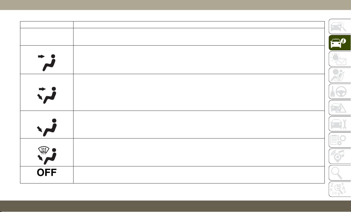
Icon Description
Mode Control
Select Mode by pressing one of the Mode buttons on the touchscreen to change the airflow distribution mode. The air-
flow distribution mode can be adjusted so air comes from the instrument panel outlets, floor outlets, defrost outlets and
demist outlets. The Mode settings are as follows:
Panel Mode
Panel Mode
Air comes from the outlets in the instrument panel. Each of these outlets can be individually adjusted to direct the flow
of air. The air vanes of the center outlets and outboard outlets can be moved up and down or side to side to regulate
airflow direction. There is a shut off wheel located below the air vanes to shut off or adjust the amount of airflow from
these outlets.
Bi-Level Mode
Bi-Level Mode
Air comes from the instrument panel outlets and floor outlets. A slight amount of air is directed through the defrost and
side window demister outlets.
NOTE:
Bi-Level mode is designed under comfort conditions to provide cooler air out of the panel outlets and warmer air from
the floor outlets.
Floor Mode
Floor Mode
Air comes from the floor outlets. A slight amount of air is directed through the defrost and side window demister out-
lets.
Mix Mode
Mix Mode
Air is directed through the floor, defrost, and side window demister outlets. This setting works best in cold or snowy con-
ditions that require extra heat to the windshield. This setting is good for maintaining comfort while reducing moisture
on the windshield.
Climate Control OFF Button
This button turns the Climate Control System off.
47

Climate Control Functions
A/C (Air Conditioning)
The Air Conditioning (A/C) button allows the
operator to manually activate or deactivate
the air conditioning system. When the air
conditioning system is turned on, cool dehu-
midified air will flow through the outlets into
the cabin. For improved fuel economy, press
the A/C button to turn off the air conditioning
and manually adjust the blower and airflow
mode settings. Also, make sure to select only
Panel, Bi-Level, or Floor modes.
NOTE:
•
For Manual Climate Controls, if the system is
in Mix, Floor or Defrost Mode, the A/C can be
turned off, but the A/C system shall remain
active to prevent fogging of the windows.
• If fog or mist appears on the windshield or
side glass, select Defrost mode, and in-
crease blower speed if needed.
• If your air conditioning performance seems
lower than expected, check the front of
the A/C condenser (located in front of the
radiator), for an accumulation of dirt or
insects. Clean with a gentle water spray
from the front of the radiator and through
the condenser.
MAX A/C
MAX A/C sets the control for maximum cool-
ing performance.
Press and release to toggle between MAX A/C
and the prior settings. The button illuminates
when MAX A/C is on.
In MAX A/C, the blower level and mode posi-
tion can be adjusted to desired user settings.
Pressing other settings will cause the MAX
A/C operation to switch to the selected set-
ting and MAX A/C to exit.
Recirculation
In cold weather, use of Recirculation mode
may lead to excessive window fogging. The
Recirculation feature may be unavailable
(button on the touchscreen greyed out) if
conditions exist that could create fogging on
the inside of the windshield.
Automatic Temperature Control (ATC)
Automatic Operation
1. Push the AUTO button on the faceplate,
or the AUTO button on the touchscreen on
the Automatic Temperature Control (ATC)
Panel.
2. Next, adjust the temperature that you
would like the system to maintain by ad-
justing the driver and passenger tempera-
ture control buttons. Once the desired
temperature is displayed, the system will
achieve and automatically maintain that
comfort level.
3. When the system is set up for your comfort
level, it is not necessary to change the
settings. You will experience the greatest
efficiency by simply allowing the system
to function automatically.
NOTE:
• It is not necessary to move the temperature
settings for cold or hot vehicles. The system
automatically adjusts the temperature,
mode, and blower speed to provide comfort
as quickly as possible.
GETTING TO KNOW YOUR VEHICLE
48

•
The temperature can be displayed in U.S. or
Metric units by selecting the US/Metric
customer-programmable feature. Refer to
the “Uconnect Settings” in “Multimedia” in
your Owner’s Manual for further information.
To provide you with maximum comfort in the
Automatic mode during cold start-ups, the
blower fan will remain on low until the engine
warms up. The blower will increase in speed
and transition into Auto mode.
Manual Operation Override
T
his system offers a full complement of
manual override features. The AUTO symbol in
the front ATC display will be turned off when
the system is being used in the manual mode.
Operating Tips
Summer Operation
The engine cooling system must be protected
with a high-quality antifreeze coolant to pro-
vide proper corrosion protection and to pro-
tect against engine overheating. OAT coolant
(conforming to MS.90032) is recommended.
Winter Operation
To ensure the best possible heater and de-
froster performance, make sure the engine
cooling system is functioning properly and
the proper amount, type, and concentration
of coolant is used. Use of the Air Recircula-
tion mode during Winter months is not rec-
ommended, because it may cause window
fogging.
Vacation/Storage
Before you store your vehicle, or keep it out of
service (i.e., vacation) for two weeks or more,
run the air conditioning system at idle for
about five minutes, in fresh air with the
blower setting on high. This will ensure ad-
equate system lubrication to minimize the
possibility of compressor damage when the
system is started again.
Window Fogging
Vehicle windows tend to fog on the inside in
mild, rainy, and/or humid weather. To clear
the windows, select Defrost or Mix mode and
increase the front blower speed. Do not use
the Recirculation mode without A/C for long
periods, as fogging may occur.
CAUTION!
Failure to follow these cautions can cause
damage to the heating elements:
•
Use care when washing the inside of the
rear window. Do not use abrasive window
cleaners on the interior surface of the
window. Use a soft cloth and a mild
washing solution, wiping parallel to the
heating elements. Labels can be peeled
off after soaking with warm water.
• Do not use scrapers, sharp instru-
ments, or abrasive window cleaners on
the interior surface of the window.
• Keep all objects a safe distance from
the window.
49
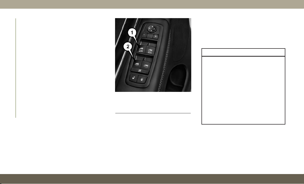
Outside Air Intake
Make sure the air intake, located directly in
front of the windshield, is free of obstruc-
tions, such as leaves. Leaves collected in the
air intake may reduce airflow, and if they
enter the plenum, they could plug the water
drains. In Winter months, make sure the air
intake is clear of ice, slush, and snow.
Cabin Air Filter
The climate control system filters out dust
and pollen from the air. Contact an autho-
rized dealer to service your cabin air filter,
and to have it replaced when needed.
WINDOWS
Power Window Controls
The window controls on the driver's door
control all the door windows.
There are single window controls on each
passenger door trim panel, which operate the
passenger door windows. The window con-
trols will operate only when the ignition is in
the ACC or ON/RUN position.
If equipped, the key fob may also be used to
raise or lower vehicle windows while the igni-
tion is in the “OFF” position. Refer to “Keys”
in “Getting To Know Your Vehicle” for further
information.
WARNING!
Never leave children unattended in a ve-
hicle, and do not let children play with
power windows. Do not leave the key fob in
or near the vehicle, or in a location acces-
sible to children, and do not leave the
ignition of a vehicle equipped with Keyless
Enter-N-Go in the ACC or ON/RUN mode.
Occupants, particularly unattended chil-
dren, can become entrapped by the win-
dows while operating the power window
switches. Such entrapment may result in
serious injury or death.
Power Window Switches
1 — Front Power Window Switches
2 — Rear Power Window Switches
GETTING TO KNOW YOUR VEHICLE
50
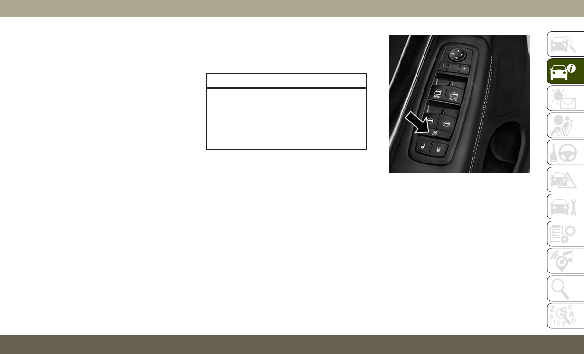
Auto-Down Feature
The driver door power window switch and
the front and rear passenger doors window
switches have an Auto-Down feature.
Push the window switch down for half a
second and release. The window will go down
automatically.
To stop the window from going all the way
down during the Auto-Down operation, pull
up or push down on the switch briefly.
To open the window part way (manually), push
the window switch down briefly and release.
Auto-Up Feature With Anti-Pinch
Protection
NOTE:
• If the window runs into any obstacle during
auto-closure, it will reverse direction and
then go back down. Remove the obstacle
and use the window switch again to close
the window.
• Any impact due to rough road conditions
may trigger the auto-reverse function unex-
pectedly during auto-closure. If this hap-
pens, pull the switch lightly and hold to
close the window manually.
WARNING!
There is no anti-pinch protection when the
window is almost closed. To avoid personal
injury be sure to clear your arms, hands,
fingers and all objects from the window
path before closing.
Window Lockout Switch
The window lockout switch on the driver's
door trim panel allows you to disable the
window controls on the rear passenger doors.
To disable the window controls, push and
release the window lockout button (the indi-
cator light on the button with turn on). To
enable the window controls, push and release
the window lockout button again (the indica-
tor light on the button will turn back off).
Wind Buffeting
Wind buffeting can be described as the percep-
tion of pressure on the ears or a helicopter-type
sound in the ears. Your vehicle may exhibit
wind buffeting with the windows down, or the
sunroof (if equipped) in certain open or par-
tially open positions. This is a normal occur-
rence and can be minimized. If the buffeting
occurs with the rear windows open, open the
front and rear windows together to minimize
Power Window Lockout Button
51
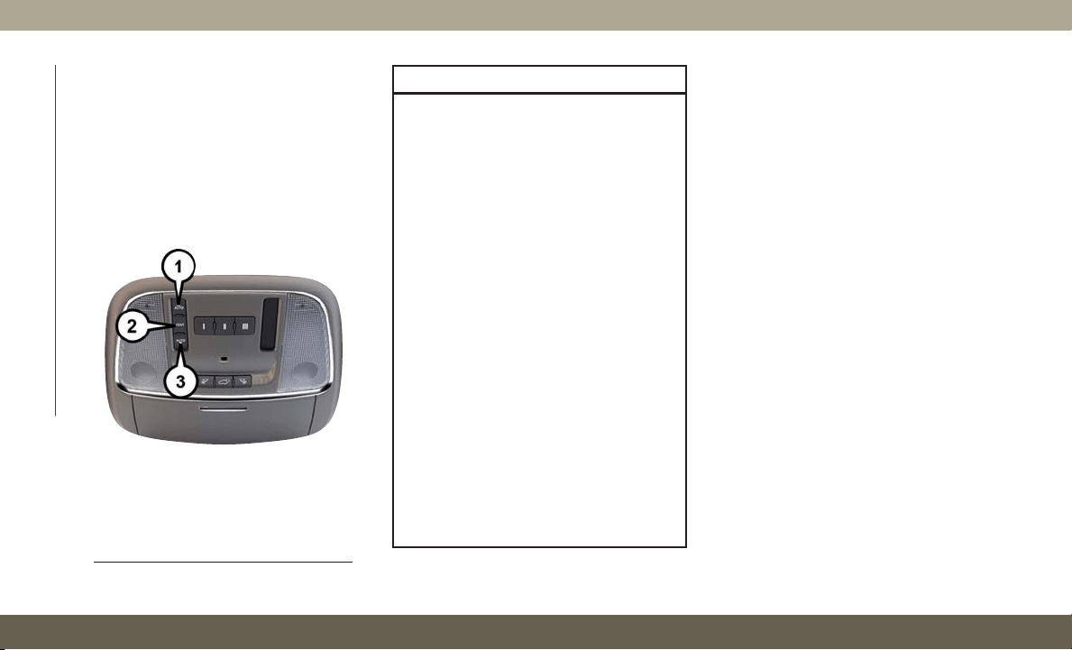
the buffeting. If the buffeting occurs with the
sunroof open, adjust the sunroof opening to
minimize the buffeting or open any window.
POWER SUNROOF —
IF EQUIPPED
The power sunroof switch is located between
the sun visors on the overhead console.
WARNING!
• Never leave children unattended in a
vehicle, or with access to an unlocked
vehicle. Never leave the key fob in or
near the vehicle, or in a location acces-
sible to children. Do not leave the igni-
tion of a vehicle equipped with Keyless
Enter-N-Go in the ACC or ON/RUN
mode. Occupants, particularly unat-
tended children, can become entrapped
by the power sunroof while operating the
power sunroof switch. Such entrapment
may result in serious injury or death.
• In a collision, there is a greater risk of
being thrown from a vehicle with an
open sunroof. You could also be seri-
ously injured or killed. Always fasten
your seat belt properly and make sure all
passengers are also properly secured.
• Do not allow small children to operate
the sunroof. Never allow your fingers,
other body parts, or any object, to proj-
ect through the sunroof opening. Injury
may result.
Opening Sunroof
Express
Push the switch rearward and release it
within one-half second and the sunroof will
open automatically from any position. The
sunroof will open fully and stop automati-
cally. This is called “Express Open”. During
Express Open operation, any other actuation
of the sunroof switch will stop the sunroof.
Manual
To open the sunroof, push and hold the
switch rearward to full open. Any release of
the switch will stop the movement. The sun-
roof and sunshade will remain in a partially
opened condition until the sunroof switch is
pushed again.
Closing Sunroof
Express
Push the switch forward and release it within
one-half second and the sunroof will close
automatically from any position. The sunroof
Power Sunroof Switch
1 — Opening Sunroof
2 — Venting Sunroof
3 — Closing Sunroof
GETTING TO KNOW YOUR VEHICLE
52

will close fully and stop automatically. This is
called “Express Close”. During Express Close
operation, any other actuation of the switch
will stop the sunroof.
Manual
T
o close the sunroof, push and hold the switch
in the forward position. Any release of the
switch will stop the movement and the sunroof
will remain in a partially closed condition until
the sunroof switch is pushed again.
Sunshade Operation
The sunshade can be opened manually. How-
ever, the sunshade will open automatically as
the sunroof opens.
NOTE:
The sunshade cannot be closed if the sunroof
is open.
Pinch Protect Feature
This feature will detect an obstruction in the
closing of the sunroof during the Express
Close operation. If an obstruction in the path
of the sunroof is detected, the sunroof will
automatically retract. Remove the obstruc-
tion if this occurs.
NOTE:
If three consecutive sunroof close attempts
result in Pinch Protect reversals, Pinch Pro-
tect will disable and the sunroof must be
closed in Manual Mode.
Venting Sunroof — Express
Push and release the Vent button within one
half second and the sunroof will open to the
vent position. This is called “Express Vent”
and it will occur regardless of sunroof posi-
tion. During Express Vent operation, any
movement of the switch will stop the sunroof.
Sunroof Maintenance
Use only a non-abrasive cleaner and a soft
cloth to clean the glass panel.
Relearn Procedure
For vehicles equipped with a single-pane sun-
roof, there is a relearn procedure that allows
you to reset the sunroof when the “Express
Open” feature stops working. To reset the sun-
roof, follow these steps:
1. Set the ignition to the ACC or ON/RUN
position.
2. Make sure that the sunroof is fully closed.
3. Push sunroof switch forward and hold.
The sunroof will close fully then move to
the Vent position after 10 seconds.
4. Release the sunroof switch, then push
forward and hold the switch again within
5 seconds to begin the relearn process.
The sunroof will complete one full cycle
and return to the Fully Closed position.
NOTE:
If the sunroof switch is released anytime
during the relearn cycle, the procedure
will need to be repeated starting from the
first step.
5. Once the sunroof has stopped in the Fully
Closed position, release the sunroof
switch. The sunroof is now reset and ready
to use.
53
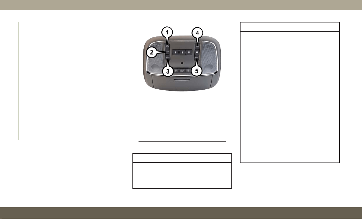
COMMANDVIEW SUNROOF
WITH POWER SHADE —
IF EQUIPPED
The CommandView sunroof switch is located
to the left between the sun visors on the
overhead console.
The power shade switch is located to the
right between the sun visors on the overhead
console.
WARNING!
• Never leave children unattended in a
vehicle, or with access to an unlocked
vehicle. Never leave the key fob in or
WARNING!
near the vehicle, or in a location acces-
sible to children. Do not leave the igni-
tion of a vehicle equipped with Keyless
Enter-N-Go in the ACC or ON/RUN
mode. Occupants, particularly unat-
tended children, can become entrapped
by the power sunroof while operating the
power sunroof switch. Such entrapment
may result in serious injury or death.
• In a collision, there is a greater risk of
being thrown from a vehicle with an
open sunroof. You could also be seri-
ously injured or killed. Always fasten
your seat belt properly and make sure all
passengers are also properly secured.
• Do not allow small children to operate
the sunroof. Never allow your fingers,
other body parts, or any object, to proj-
ect through the sunroof opening. Injury
may result.
Commandview Sunroof Switches
1 — Opening Sunroof
2 — Venting Sunroof
3 — Closing Sunroof
4 — Opening Shade
5 — Closing Shade
GETTING TO KNOW YOUR VEHICLE
54

Opening Sunroof
The sunroof has two programmed automatic
stops for the sunroof open position; a comfort
stop position and a full open position. The
comfort stop position has been optimized to
minimize wind buffeting.
Express
Push the switch rearward and release it
within one-half second. The sunroof will open
automatically to the comfort stop position.
Push the switch rearward and release it
again, the sunroof will open to the full open
position and automatically stop. This is
called “Express Open”. During Express Open
operation, any movement of the sunroof
switch will stop the sunroof.
Manual Mode
To open the sunroof, push and hold the
switch rearward. The sunroof will stop auto-
matically at the comfort stop position. Push
and hold the switch rearward again, the sun-
roof will open to the full open position and
automatically stop. Any release of the switch
will stop the movement. The sunroof and
sunshade will remain in a partially opened
condition until the switch is pushed and held
rearward again.
NOTE:
If the sunshade is in the closed position when
Express or Manual Open operation is initiated
the sunshade will automatically open to the
half open position prior to the sunroof opening.
Closing Sunroof
Express Close
Push the switch forward and release it within
one-half second and the sunroof will close
automatically from any position. During Ex-
press Close operation, any other actuation of
the sunroof switches will stop the sunroof in a
partially open position.
Manual Close
Push and hold the switch forward and the
sunroof will close from any position and stop
at full closed position. Releasing the switch
while the sunroof is in motion will stop the
sunroof in a partially open position.
Opening Power Shade
T
he sunshade has two programmed positions:
half open and full open positions. When oper-
ating the sunshade from the closed position,
the sunshade will always stop at the half open
position regardless of express or manual open
operation. The switch must be actuated again
to continue on to full open position.
Express Open
Push the sunshade switch rearward and re-
lease it within one-half second, the sunshade
will open to the half open position and stop
automatically. Push and release the switch
again from the half open position and the
sunshade will open to the full open position
and stop automatically. During Express Open
operation, any other actuation of the sunroof
switches will stop the sunshade in a partially
open position.
55

Manual Open
Push and hold the sunshade switch rearward,
the sunshade will open to the half open
position and stop automatically. Push and
hold the sunshade switch again and the sun-
shade will open to the full open position.
Releasing the switch while the sunshade is in
motion will stop the sunshade in a partially
open position.
Closing Power Shade
If the sunroof is open or vented, the sunshade
cannot be closed beyond the half open posi-
tion. Pushing the sunshade close switch
when the sunroof is open/vented and the
sunshade is at half open position will first
automatically close the sunroof prior to the
sunshade closing.
Express Close
Push the sunshade switch forward and re-
lease it within one-half second and the
sunshade will close automatically. During
Express Close operation, any other actuation
of the sunroof switches will stop the sun-
shade in a partially open position.
Manual Close
Push and hold the switch forward and the
sunshade will close and stop at full closed
position. Releasing the switch while the sun-
shade is in motion will stop the sunshade in a
partially open position.
Pinch Protect Feature
This feature will detect an obstruction in the
opening of the sunroof during Express Close
operation. If an obstruction in the path of the
sunroof is detected, the sunroof will auto-
matically retract. Remove the obstruction if
this occurs.
NOTE:
If three consecutive sunroof close attempts
result in Pinch Protect reversals, Pinch Pro-
tect will disable and the sunroof must be
closed in Manual Mode.
Venting Sunroof — Express
Push and release the "Vent" button within
one-half second and the sunroof will open to
the vent position. This is called “Express
Vent”, and it will occur regardless of sunroof
position. During Express Vent operation, any
movement of the switch will stop the sunroof.
NOTE:
If the sunshade is in the closed position when
the vent switch is pushed, the sunshade will
automatically cycle to the halfway open posi-
tion prior to the sunroof opening to the Vent
position.
Sunroof Maintenance
Use only a non-abrasive cleaner and a soft
cloth to clean the glass panel.
GETTING TO KNOW YOUR VEHICLE
56
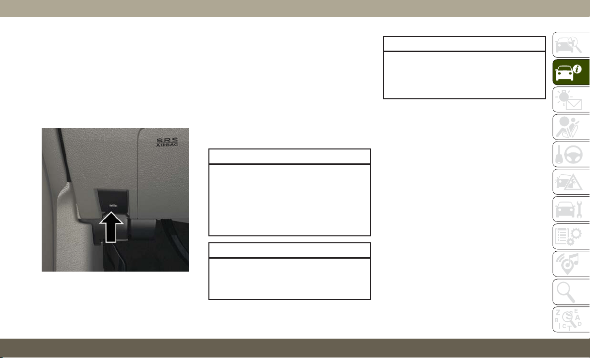
HOOD
To Open The Hood
To open the hood, two latches must be re-
leased.
1. Pull the release lever located below the
instrument panel and in front of the driv-
er's door.
2. Reach under the hood, move safety latch
to the left and lift the hood.
To Close The Hood
1. Hold up the hood with one hand and with
the other hand remove the support rod
from its seat and reinsert it into the lock-
ing tab.
2.
Lower the hood to approximately 12 inches
(30 cm) from the engine compartment and
drop it. Make sure that the hood is com-
pletely closed.
WARNING!
Be sure the hood is fully latched before
driving your vehicle. If the hood is not fully
latched, it could open when the vehicle is
in motion and block your vision. Failure to
follow this warning could result in serious
injury or death.
CAUTION!
To prevent possible damage, do not slam
the hood to close it. Lower hood to approxi-
mately 12 inches (30 cm) and drop the
CAUTION!
hood to close. Make sure hood is fully
closed for both latches. Never drive ve-
hicle unless hood is fully closed, with both
latches engaged.
LIFTGATE
Opening
The liftgate can be opened from inside the
vehicle using the power liftgate button on the
overhead console, using the key fob outside
of the vehicle or the electronic liftgate re-
lease.
To Unlock/Enter The Liftgate
The liftgate may be released in several ways:
• Key fob
• Outside handle
• Button on overhead console
Hood Release Lever
57
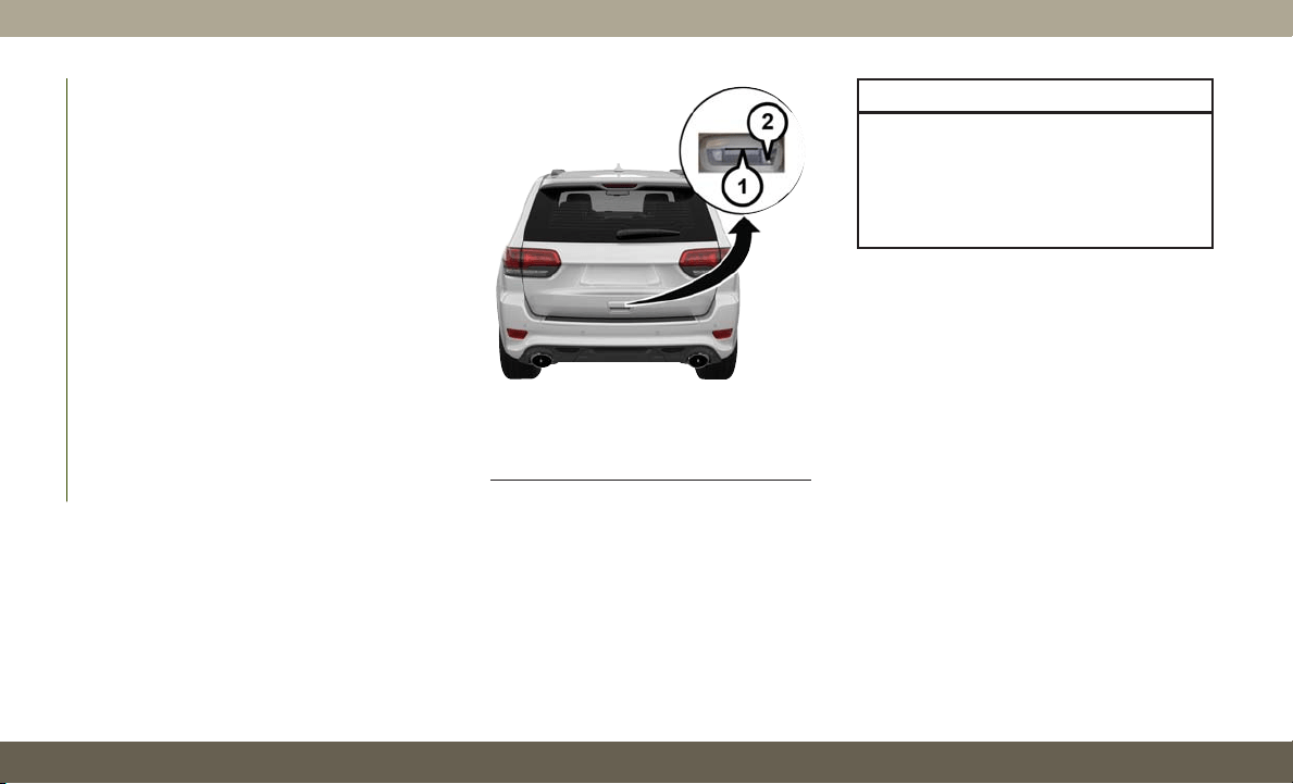
The liftgate passive entry unlock feature is
built into the electronic liftgate release. With
a valid Passive Entry key fob within 5 ft
(1.5 m) of the liftgate, push the electronic
liftgate release to open with one fluid motion.
Push the button on the key fob twice within
five seconds to release the liftgate.
NOTE:
If “Unlock All Doors 1st Press” is pro-
grammed in the instrument cluster display,
all doors will unlock when you push the
electronic release on the liftgate. If "Unlock
Driver Door 1st Press" is programmed in
Uconnect, only the liftgate will unlock when
you push the electronic release on the lift-
gate. Refer to “Uconnect Settings” in “Mul-
timedia” in the Owner’s Manual for further
information.
NOTE:
Use the power door lock switch on either front
door trim panel or the key fob to lock and
unlock the liftgate. The manual door locks on
the doors and the driver's door lock cylinder
will not lock and unlock the liftgate.
WARNING!
Driving with the liftgate open can allow
poisonous exhaust gases into your vehicle.
You and your passengers could be injured
by these fumes. Keep the liftgate closed
when you are operating the vehicle.
Closing
To manually close the liftgate, grasp the lift-
gate closing handle and initiate the lowering
of the liftgate. Release the handle when the
liftgate is partially closed and the momentum
will fully close the liftgate.
To Lock The Liftgate
With a valid Passive Entry key fob within 5 ft
(1.5 m) of the liftgate, pushing the Keyless
Enter-N-Go — Passive Entry lock button lo-
cated to the left of the outside handle release
will lock the vehicle.
Passive Entry/Lock Button Location
1 — Electronic
Liftgate Release
2 — Lock Button
Location
GETTING TO KNOW YOUR VEHICLE
58
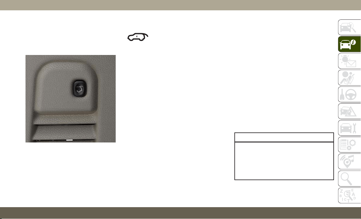
The power liftgate may be closed by pushing
the button, located in the upper left trim in
the liftgate opening. Pushing button will only
close the liftgate. This button cannot be used
to open the liftgate.
NOTE:
The liftgate unlock feature is built into the
electronic liftgate release.
Power Liftgate — If Equipped
The power liftgate may be
opened by pushing the electronic
liftgate release (refer to “Keyless
Enter-N-Go — Passive Entry” located in
“Getting To Know Your Vehicle” in your Own-
er’s Manual for further information), or by
pushing the liftgate button on the key fob.
Push the liftgate button on the key fob twice
within five seconds to open the power lift-
gate. Once the liftgate is open, pushing the
button twice within five seconds a second
time will close the liftgate.
The power liftgate may also be opened or
closed by pushing the liftgate button located
on the front overhead console. If the liftgate
is fully open, the liftgate can be closed by
pushing the liftgate button located on the left
rear trim panel, near the liftgate opening. If
the liftgate is in motion, pushing the liftgate
button located on the left rear trim panel will
reverse the liftgate.
When the liftgate button on the key fob is
pushed two times, the turn signals will flash
to signal that the liftgate is opening or closing
(if Flash Lamps with Lock is enabled in the
Uconnect settings), and the liftgate chime
will be audible. Refer to "Uconnect Settings"
in "Multimedia” in the Owner’s Manual for
further information.
NOTE:
• In the event of a power malfunction to the
liftgate, an emergency liftgate latch release
can be used to open the liftgate. The emer-
gency liftgate latch release can be ac-
cessed through a snap-in cover located on
the liftgate trim panel.
•If
liftgate is left open for an extended period
of time, the liftgate may need to be closed
manually to reset power liftgate functionality.
WARNING!
During power operation, personal injury or
cargo damage may occur. Ensure the lift-
gate travel path is clear. Make sure the
liftgate is closed and latched before driv-
ing away.
Rear Power Liftgate Switch
2
59
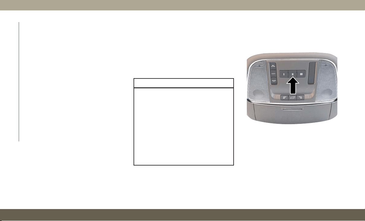
NOTE:
• The power liftgate will not operate in tem-
peratures below −22°F (−30°C) or tem-
peratures above 150° F (65° C). Be sure to
remove any buildup of snow or ice from the
liftgate before pushing any of the power
liftgate switches.
• If anything obstructs the power liftgate
while it is closing or opening, the liftgate
will automatically reverse to the closed or
open position, provided it meets sufficient
resistance.
• There are also pinch sensors attached to
the side of the liftgate. Light pressure any-
where along these strips will cause the
liftgate to return to the open position.
• If the liftgate is not fully open, push the
liftgate button on the key fob twice to
operate the liftgate.
• If the electronic liftgate release is pushed
while the power liftgate is closing, the lift-
gate will reverse to the full open position.
• If the electronic liftgate release is pushed
while the power liftgate is opening, the
liftgate motor will disengage to allow
manual operation.
• If the power liftgate encounters multiple
obstructions within the same cycle, the
system will automatically stop and the lift-
gate must be opened or closed manually.
WARNING!
• Driving with the liftgate open can allow
poisonous exhaust gases into your ve-
hicle. You and your passengers could be
injured by these fumes. Keep the liftgate
closed when you are operating the ve-
hicle.
• If you are required to drive with the
liftgate open, make sure that all win-
dows are closed, and the climate control
blower switch is set at high speed. Do
not use the recirculation mode.
UNIVERSAL GARAGE DOOR
OPENER (HOMELINK)
• HomeLink replaces up to three hand-held
transmitters that operate devices such as
garage door openers, motorized gates,
lighting or home security systems. The
HomeLink unit is powered by your vehicles
12 Volt battery.
HomeLink Buttons And Indicator Light
GETTING TO KNOW YOUR VEHICLE
60

• The HomeLink buttons that are located in
the overhead console or sunvisor designate
the three different HomeLink channels.
• To operate HomeLink, push and release any
of the programmed HomeLink buttons.
These buttons will activate the devices they
are programmed to with each press of the
corresponding HomeLink button.
• The HomeLink indicator light is located
above the center button.
Before You Begin Programming HomeLink
F
or efficient programming and accurate trans-
mission of the radio-frequency signal, it is
recommended that a new battery be placed in
the hand-held transmitter of the device that is
being programmed to the HomeLink system.
Make sure your hand-held transmitter is pro-
grammed to activate the device you are trying
to program your HomeLink button to.
Ensure that your vehicle is parked outside of
the garage before you begin programming.
It is recommended that you erase all the
channels of your HomeLink before you use it
for the first time.
If you have any problems, or require assis-
tance, please call toll-free 1-800-355-3515
or, on the Internet at HomeLink.com for in-
formation or assistance.
Erasing All The HomeLink Channels
To erase the channels, follow this procedure:
1. Place the ignition switch into the ON/RUN
position.
2. P
ush and hold the two outside HomeLink
buttons (I and III) for up to 20 seconds, or
until the HomeLink indicator light flashes.
NOTE:
Erasing all channels should only be per-
formed when programming HomeLink for the
first time. Do not erase channels when pro-
gramming additional buttons.
Identifying Whether You Have A Rolling
Code Or Non-Rolling Code Device
Before programming a device to one of your
HomeLink buttons, you must determine
whether the device has a rolling code or
non-rolling code.
Rolling Code Devices
To determine if your device has a rolling code,
a good indicator is its manufacturing date.
Typically, devices manufactured after
1995 have rolling codes. A device with a
rolling code will also have a “LEARN” or
“TRAIN” button located where the antenna is
attached to the device. The button may not
be immediately visible when looking at the
device. The name and color of the button may
vary slightly by manufacturer.
NOTE:
The “LEARN” or “TRAIN” button is not the
button you normally use to operate the de-
vice.
Non-rolling Code Devices
Most devices manufactured before 1995 will
not have a rolling code. These devices will
also not have a “LEARN” or “TRAIN” button.
61

Programming HomeLink To A Garage
Door Opener
To program any of the HomeLink buttons to
activate your garage door opener motor, fol-
low the steps below:
NOTE:
All HomeLink buttons are programmed using
this procedure. You do not need to erase all
channels when programming additional but-
tons.
1. Place the ignition switch into the ON/RUN
position.
2. Place the garage door opener transmitter
1 to 3 inches (3 to 8 cm) away from the
HomeLink button you wish to program,
while keeping the HomeLink indicator
light in view.
3. Push and hold the HomeLink button you
want to program while you push and hold
the garage door opener transmitter button
you are trying to replicate.
4. Continue to hold both buttons and ob-
serve the HomeLink indicator light. The
HomeLink indicator light will flash slowly
and then rapidly. Once this happens, re-
lease both buttons.
NOTE:
Make sure the garage door opener motor is
plugged in before moving on to the rolling
code/non-rolling code final steps.
Rolling Code Garage Door Opener Final Steps
NOTE:
You have 30 seconds in which to initiate
rolling code final step 2, after completing
rolling code final step 1.
1. At the garage door opener motor (in the
garage), locate the “LEARN” or “TRAIN”
button. This can usually be found where
the hanging antenna wire is attached to
the garage door opener motor. Firmly push
and release the “LEARN” or “TRAIN”
button.
2. Return to the vehicle and push the pro-
grammed HomeLink button three times
(holding the button for two seconds each
time). If the garage door opener motor
operates, programming is complete.
3. Push the programmed HomeLink button
to confirm that the garage door opener
motor operates. If the garage door opener
motor does not operate, repeat the final
steps for the rolling code procedure.
Non-Rolling Code Garage Door Opener Final
Steps
1.
Push and hold the programmed HomeLink
button and observe the HomeLink indicator
light. If the HomeLink indicator light stays
on constantly, programming is complete.
2. Push the programmed HomeLink button
to confirm that the garage door opener
motor operates. If the garage door opener
motor does not operate, repeat the steps
from the beginning.
GETTING TO KNOW YOUR VEHICLE
62
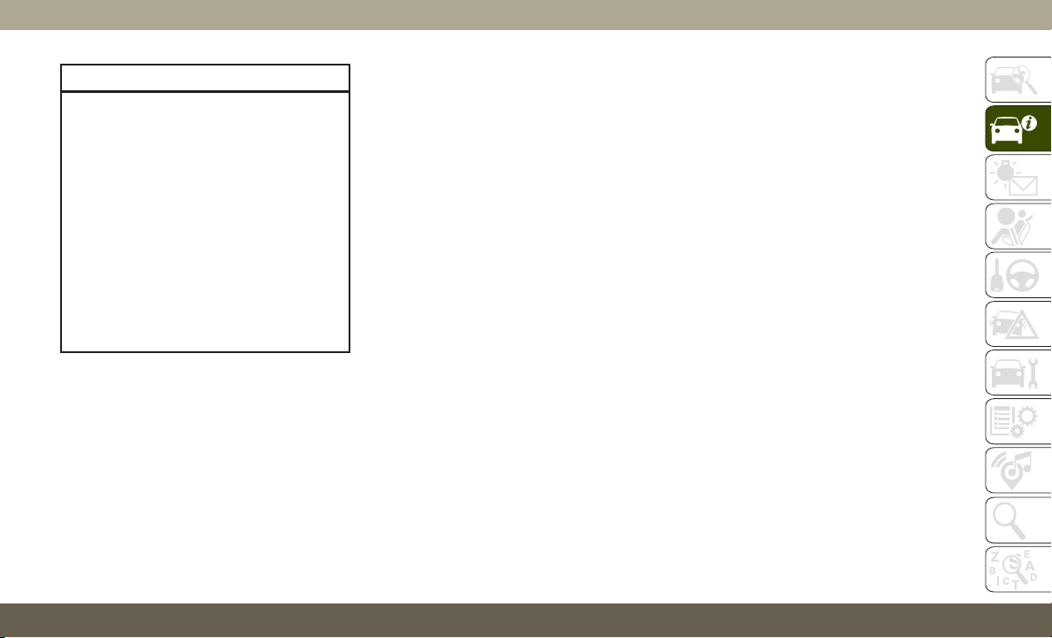
WARNING!
• Your motorized door or gate will open
and close while you are programming
the universal transceiver. Do not pro-
gram the transceiver if people or pets
are in the path of the door or gate.
• Do not run your vehicle in a closed
garage or confined area while program-
ming the transceiver. Exhaust gas from
your vehicle contains Carbon Monoxide
(CO) which is odorless and colorless.
Carbon Monoxide is poisonous when
inhaled and can cause you and others
to be severely injured or killed.
Programming HomeLink To A
Miscellaneous Device
Refer to “Programming HomeLink To A Ga-
rage Door Opener” for the procedure on how
to program HomeLink to a miscellaneous
device, as it follows the same procedure. Be
sure to determine if the device has a rolling
code, or non-rolling code before beginning
the programming process.
NOTE:
Canadian radio frequency laws require trans-
mitter signals to time-out (or quit) after sev-
eral seconds of transmission, which may not
be long enough for HomeLink to pick up the
signal during programming. Similar to this
Canadian law, some U.S. gate operators are
designed to time-out in the same manner.
The procedure may need to be preformed
multiple times to successfully pair the device
to your HomeLink buttons.
Reprogramming A Single HomeLink
Button
To reprogram a single HomeLink button that
has been previously trained, without erasing
all the channels, follow the procedure below.
Be sure to determine whether the new device
you want to program the HomeLink button to
has a Rolling Code, or Non-rolling Code.
1. Cycle the ignition to the ON/RUN posi-
tion, without starting the engine.
2. Push and hold the desired HomeLink but-
ton until the HomeLink Indicator light
begins to flash after 20 seconds. Do not
release the button.
3. Without releasing the button, proceed with
Step 2 in “Programming HomeLink To
A Garage Door Opener” and follow all
remaining steps.
General Information
The following regulatory statement applies to
all Radio Frequency (RF) devices equipped in
this vehicle:
This device complies with Part 15 of the FCC
Rules and with Innovation, Science and Eco-
nomic Development Canada license-exempt
RSS standard(s). Operation is subject to the
following two conditions:
1. This device may not cause harmful inter-
ference, and
2. This device must accept any interference
received, including interference that may
cause undesired operation.
NOTE:
Changes or modifications not expressly ap-
proved by the party responsible for compli-
ance could void the user’s authority to oper-
ate the equipment.
63
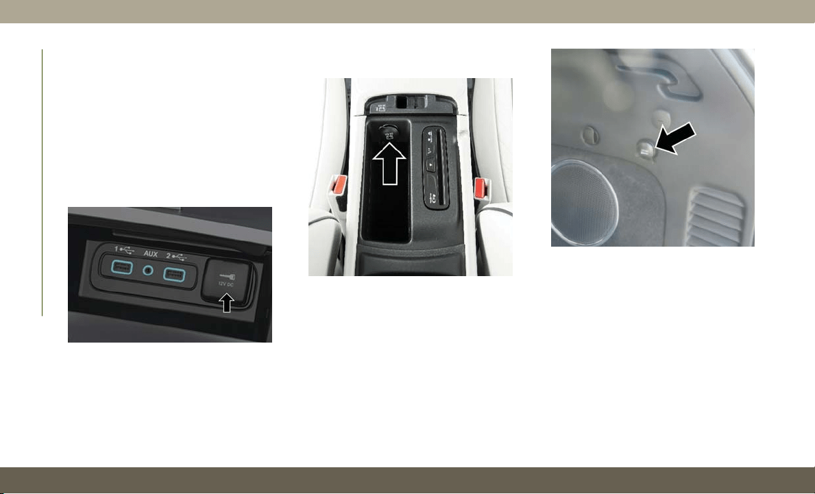
INTERNAL EQUIPMENT
Power Outlets
If equipped, there may be three 12 Volt
electrical power outlets on this vehicle.
The front power outlet may be located inside
the center storage bin of the instrument
panel. Push inward on the storage lid to open
the compartment and gain access to this
power outlet.
A second front power outlet may be located
inside the center console.
The rear power outlet may be located in the
right rear cargo area.
The power outlets are labeled with either a
“key” or a “battery” symbol to indicate how
the outlet is powered. Power outlets labeled
with a “key” are powered when the ignition
switch is in the ON/RUN or ACC position,
while the outlets labeled with a “battery” are
connected directly to the battery and pow-
ered at all times.
Front Power Outlet
Center Console Power Outlet
Rear Cargo Power Outlet
GETTING TO KNOW YOUR VEHICLE
64
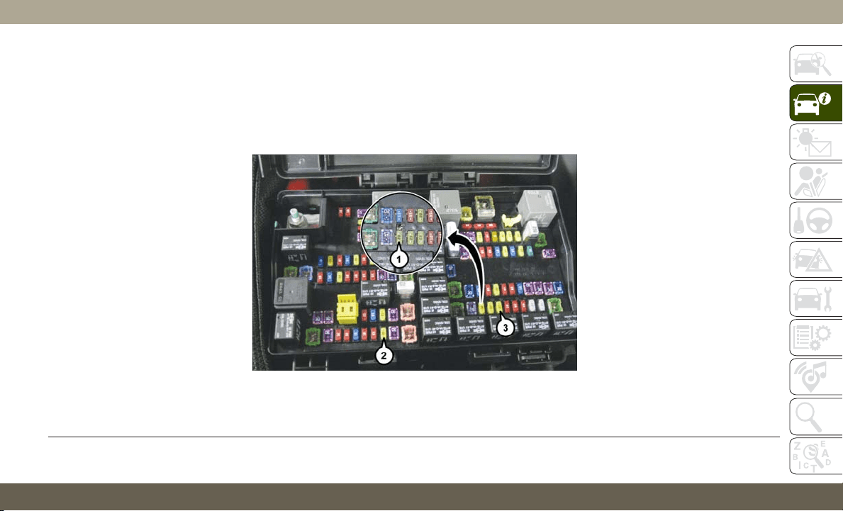
NOTE:
• Do not exceed the maximum power of
160 Watts (13 Amps) at 12 Volts. If the
160 Watt (13 Amp) power rating is ex-
ceeded, the fuse protecting the system will
need to be replaced.
• Power outlets are designed for accessory
plugs only. Do not insert any other object in
the power outlet as this will damage the
outlet and blow the fuse. Improper use of
the power outlet can cause damage not
covered by your new vehicle warranty.
• The rear cargo power outlet can be switched
to “battery” powered all the time by switch-
ing the power outlet right rear quarter panel
fuse in the fuse panel.
Power Outlet Fuse Locations
1 — F90 – F91 Fuse 20A Yellow Power Outlet Right Rear Quarter Panel
2 — F104 Fuse 20A Yellow Power Outlet Center Console
3 — F93 Fuse 20A Yellow Cigar Lighter Instrument Panel
65
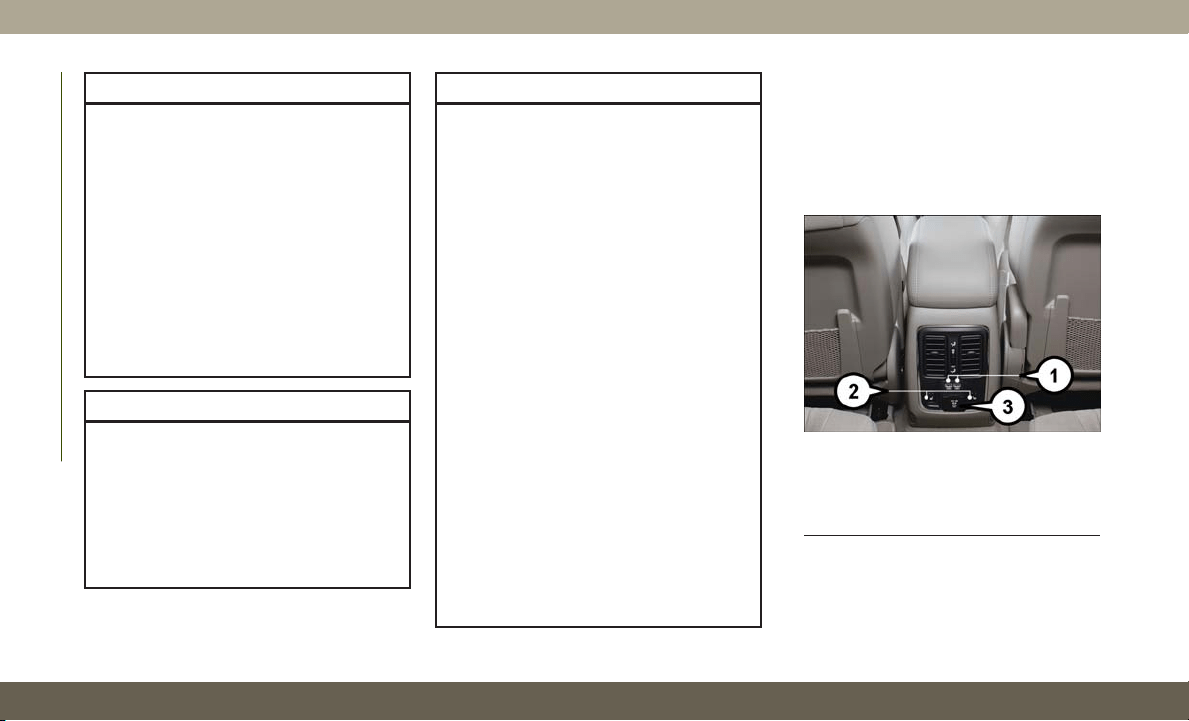
CAUTION!
• Do not exceed the maximum power of
160 Watts (13 Amps) at 12 Volts. If the
160 Watt (13 Amp) power rating is ex-
ceeded the fuse protecting the system
will need to be replaced.
• Power outlets are designed for accessory
plugs only. Do not insert any other object
in the power outlets as this will damage
the outlet and blow the fuse. Improper
use of the power outlet can cause dam-
age not covered by your New Vehicle
Limited Warranty.
WARNING!
To avoid serious injury or death:
• Do not insert any objects into the
receptacles.
• Do not touch with wet hands.
• Close the lid when not in use.
• If this outlet is mishandled, it may
cause an electric shock and failure.
CAUTION!
• Many accessories that can be plugged in
draw power from the vehicle's battery,
even when not in use (i.e., cellular
phones, etc.). Eventually, if plugged
in long enough, the vehicle's battery
will discharge sufficiently to degrade
battery life and/or prevent the engine
from starting.
• Accessories that draw higher power (i.e.,
coolers, vacuum cleaners, lights, etc.),
will degrade the battery even more
quickly. Only use these intermittently
and with greater caution.
•
After the use of high power draw accesso-
ries, or long periods of the vehicle not
being started (with accessories still
plugged in), the vehicle must be driven a
sufficient length of time to allow the al-
ternator to recharge the vehicle's battery.
• Power outlets are designed for accessory
plugs only. Do not hang any type of
accessory or accessory bracket from the
plug. Improper use of the power outlet
can cause damage.
Power Inverter
There is a 115 Volt, 150 Watt power inverter
outlet located on the back of the center
console. This outlet can power cellular
phones, electronics and other low power de-
vices requiring power up to 150 Watts.
Power Inverter
1 — USB Ports (Charging Only)
2 — Rear Seat Heater Switches
3 — Power Inverter Outlet
GETTING TO KNOW YOUR VEHICLE
66
NOTE:
The power inverter is designed with built-in
overload protection. If the power rating of
150 Watts is exceeded, the power inverter
will automatically shut down. Once the elec-
trical device has been removed from the out-
let, the inverter should automatically reset. If
the power rating exceeds approximately
170 Watts, the power inverter may have to be
reset manually. To reset the inverter manu-
ally, unplug the device and plug it in again. To
avoid overloading the circuit, check the
power ratings on electrical devices prior to
using the inverter.
WARNING!
To avoid serious injury or death, DO NOT:
• insert any objects into the receptacles
• touch with wet hands
Close the lid when not in use. If this outlet
is mishandled, it may cause an electric
shock and failure.
ROOF LUGGAGE RACK —
IF EQUIPPED
The crossbars and siderails are designed to
carry the weight on vehicles equipped with a
luggage rack. The load must not exceed
150 lbs (68 kg), and should be uniformly
distributed over the luggage rack crossbars.
NOTE:
If not equipped with crossbars, your autho-
rized dealer can order and install Mopar
crossbars built specifically for this roof rack
system.
Distribute cargo weight evenly on the roof rack
crossbars. The roof rack does not increase the
total load carrying capacity of the vehicle. Be
sure the total load of cargo inside the vehicle
plus that on the external rack does not exceed
the maximum vehicle load capacity.
To move the crossbars, loosen the attach-
ments, located at the upper edge of each
crossbar, approximately eight turns using the
anti-theft wrench provided with the Mopar
crossbars. Then, move the crossbar to the
desired position, keeping the crossbars par-
allel to the rack frame. Once the crossbar is in
the desired position, retighten the with the
wrench to lock the crossbar into position.
NOTE:
• To help control wind noise when the cross-
bars are not in use, place the front and rear
crossbars approximately 24 inches (61 cm)
apart. Optimal noise reduction can then be
achieved by adjusting the front crossbar
forward or aft using increments of 1 inch
(2.5 cm).
• If any cargo (or any metallic object) is
placed over the satellite radio antenna
(if equipped), you may experience interrup-
tion of satellite radio reception. For im-
proved satellite radio reception, avoid plac-
ing the rear crossbar over the satellite radio
antenna.
67

WARNING!
Cargo must be securely tied down before
driving your vehicle. Improperly secured
loads can fly off the vehicle, particularly at
high speeds, resulting in personal injury or
property damage. Follow the roof rack cau-
tions when carrying cargo on your roof
rack.
CAUTION!
• To prevent damage to the roof of your
vehicle, do not carry any loads on the
roof rack without the crossbars installed.
The load should be secured and placed
on top of the crossbars, not directly on
the roof. If it is necessary to place the
CAUTION!
load on the roof, place a blanket or some
other protection between the load and
the roof surface.
• To avoid damage to the roof rack and
vehicle, do not exceed the maximum
roof rack load capacity of 150 lb
(68 kg). Always distribute heavy loads as
evenly as possible and secure the load
appropriately.
• Long loads which extend over the wind-
shield, such as wood panels or surf-
boards, or loads with large frontal area
should be secured to both the front and
rear of the vehicle.
• Place a blanket or other protection be-
tween the surface of the roof and the
load.
CAUTION!
• Travel at reduced speeds and turn cor-
ners carefully when carrying large or
heavy loads on the roof rack. Wind
forces, due to natural causes or nearby
truck traffic, can add sudden upward lift
to a load. This is especially true on large
flat loads and may result in damage to
the cargo or your vehicle.
• The use of Sport Mode is not recom-
mended when using the Roof Luggage
Rack to carry a load.
GETTING TO KNOW YOUR VEHICLE
68

INSTRUMENT CLUSTER
DISPLAY
Your vehicle will be equipped with an instru-
ment cluster display, which offers useful in-
formation to the driver. With the ignition in
the STOP/OFF mode, opening/closing of a
door will activate the display for viewing, and
display the total miles, or kilometers, in the
odometer. Your instrument cluster display is
designed to display important information
about your vehicle’s systems and features.
Using a driver interactive display located on
the instrument panel, your instrument cluster
display can show you how systems are work-
ing and give you warnings when they are not.
The steering wheel mounted controls allow
you to scroll through the main menus and
submenus. You can access the specific infor-
mation you want and make selections and
adjustments.
Instrument Cluster Display Location And
Controls
The instrument cluster display is located in
the center of the instrument cluster.
1. The interactive display area to the left side
of the screen depicts which menus are
being accessed in the main display area.
2.
The top line where reconfigurable telltales,
compass direction, outside temperature,
Time, Range MPG or Trip are displayed.
This also displays the speedometer when
other menu pages are displayed.
3. The main display area where the menus
and pop up messages are displayed.
4.
The lower line where reconfigurable telltales,
menu name and menu page are displayed.
Instrument Cluster Display
1 — Driver Interactive Display
2 — Speedometer Display
3 — Main Display
4 — Menu Name And Menu Page
Instrument Cluster Display Controls
69

• Push the up arrow button to scroll upward
through the main menus (Speedometer,
MPH/km/h, Vehicle Info, Terrain, Driver
Assist, Fuel Economy, Trip A, Trip B, Stop/
Start, Audio, Navigation, Stored Messages,
Screen Setup and Speed Warning).
• Push the down arrow button to scroll down-
ward through the main menu and sub-
menus (Speedometer, MPH/km/h, Vehicle
Info, Terrain, Driver Assist, Fuel Economy,
Trip A, Trip B, Stop/Start, Audio, Naviga-
tion, Stored Messages, Screen Setup and
Speed Warning).
• Push the right arrow button to access the
information screens or submenu screens of
a main menu item.
• Push the left arrow button to access the
information screens or submenu screens of
a main menu item.
• Push the OK button to access/select the
information screens or submenu screens of
a main menu item. Push and hold the OK
button for two seconds to reset displayed/
selected features that can be reset.
Oil Change Reset — If Equipped
Your vehicle may be equipped with an engine
oil change indicator system. The “Oil Change
Required” message will display in the instru-
ment cluster display for five seconds after a
single chime has sounded to indicate the
next scheduled oil change interval. The en-
gine oil change indicator system is duty cycle
based, which means the engine oil change
interval may fluctuate, dependent upon your
personal driving style.
Unless reset, this message will continue to
display each time you place the ignition in
the ON/RUN position. To turn off the mes-
sage temporarily, push and release the OK
button. To reset the oil change indicator sys-
tem (after performing the scheduled mainte-
nance), refer to the following procedure.
Oil Life Reset
1. Without pushing the brake pedal, place
the ignition in the ON/RUN mode (do not
start the engine).
2. Navigate to "Oil Life" submenu in "Vehicle
Info" in the instrument cluster display.
3. Push and hold the OK button until the
gauge resets to 100%.
Secondary Method For Oil Change Reset
Procedure
1. Without pushing the brake pedal, place
the ignition in the ON/RUN position (do
not start the engine).
2. Fully press the accelerator pedal, slowly,
three times within ten seconds.
3. Without pushing the brake pedal, place
the ignition in the OFF/LOCK position.
NOTE:
If the indicator message illuminates when
you start the vehicle, the oil change indicator
system did not reset. If necessary, repeat this
procedure.
GETTING TO KNOW YOUR INSTRUMENT PANEL
70
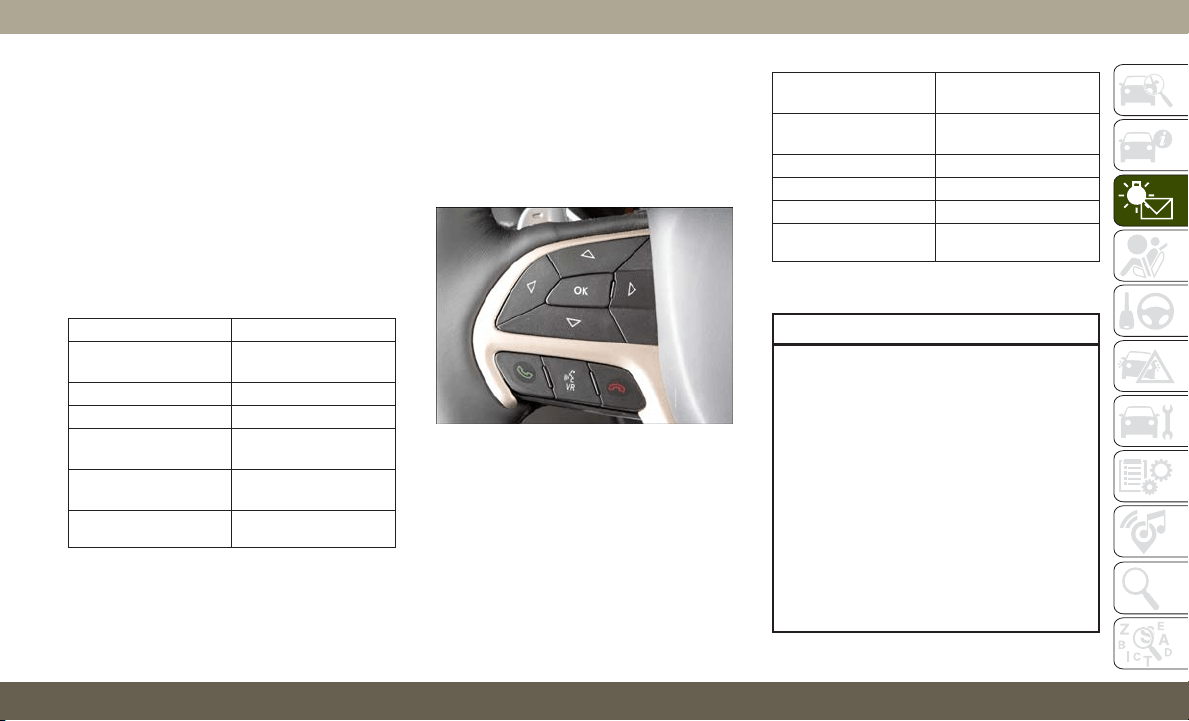
Instrument Cluster Display Selectable
Items
The instrument cluster display can be used to
view the main menu items for several features.
Use the
up and down arrow buttons to scroll
through the driver interactive display menu
options until the desired menu is reached.
NOTE:
Depending on the vehicle’s options, feature
settings may vary.
Speedometer Trip
Accessibility —
If Equipped
Audio
Vehicle Info Stored Messages
Driver Assist Screen Setup
Stop/Start —
If Equipped
Terrain —
If Equipped
Performance Features
— If Equipped
Diagnostics —
If Equipped
Fuel Economy Speed Warning
Refer to “Instrument Cluster Display” in
“Getting To Know Your Instrument Panel” in
the Owner’s Manual for further information.
Display Menu items
SRT Instrument Cluster Display Performance
Features
The instrument cluster display can be used to
program the following Performance Features.
• To access, press and release either the up or
down arrow button until “SRT” appears in
the instrument cluster display, then press
and release the right arrow button to cycle
through the features. Press the OK button to
select a feature.
0-60 MPH
(0-100 km/h)
Current G-Force
0-100 MPH
(0-161 km/h)
Peak G-Force
1/8 Mile Timer Lap Timer
1/4 Mile Timer Lap History
60 ft Timer Top Speed
Braking Distance
Uconnect SRT Performance Features
WARNING!
Measurement of vehicle statistics with the
Performance Features is intended for off-
highway or track use only and should not
be done on any public roadways. It is
recommended that these features be used
in a controlled environment and within the
limits of the law. The capabilities of the
vehicle as measured by the performance
pages must never be exploited in a reck-
less or dangerous manner, which can jeop-
ardize the user’s safety or the safety of
others. Only a safe, attentive, and skillful
driver can prevent accidents.
SRT Performance Features Controls
71

•T
o access the SRT Performance Features,
press the “Apps” button on the touchscreen
then press the “Performance Pages” button
on the touchscreen.
• The Performance Page includes the follow-
ing menus:
•
Home
•
Gauges 2
•
Timers
•
G – Force
•
Gauges 1
•
Engine
Diesel Exhaust Fluid (DEF) Warning Messages
Your vehicle will begin displaying warning
messages when the DEF level reaches a driv-
ing range of approximately 500 miles. If the
following warning message sequence is ig-
nored, your vehicle may not restart unless
DEF is added with in the mileage shown in
the instrument cluster display message.
• Engine Will Not Restart in XXXX mi DEF Low
Refill Soon — This message will display
when DEF driving range is less than
500 miles, DEF fluid top off is required
with in the displayed mileage. The message
will be shown in the display during vehicle
start up with the current allowed mileage
and accompanied by a single chime. The
remaining mileage can be pulled up any-
time by way of the “Messages” list within
the instrument cluster display.
• Engine Will Not Restart in XXXX mi Refill DEF
— This message will display when DEF
driving range is less than 311 miles. It is
also displayed at 249 miles, 186 miles,
and 124 miles. Continuous Display starts
at 124 miles. DEF fluid top off is required
with in the displayed mileage. The message
will be shown in the display during vehicle
start up with an updated distance mileage,
and it will be accompanied by a single
chime. Starting at 100 miles, remaining
range will be continuously displayed while
operating the vehicle. Chimes will also ac-
company the 75, 50 and 25 mile remaining
distances. The DEF Low telltale will be on
continuously until DEF fluid is topped off.
• Engine Will Not Restart Refill DEF — This
message will display when the DEF driving
range is less than 1 mile, DEF fluid top off
is required or the engine will not restart.
The message will be shown in the instru-
ment cluster display during vehicle start
up, and it will be accompanied by a single
chime. The DEF Low telltale will be illumi-
nated continuously until DEF fluid tank
is filled with a minimum of 2 gallons
(7.5 liters) of DEF.
Diesel Exhaust Fluid (DEF) Fault Warning
Messages
There are different messages which are dis-
played if the vehicle detects that the DEF
system has been filled with a fluid other than
DEF, has experienced component failures, or
when tampering has been detected.
When the DEF system needs to be serviced
the following warnings will display:
• Service DEF System See Dealer —
This mes-
sage will display when the fault is initially
detected and each time the vehicle is
started. The message will be accompanied
by a single chime and the Malfunction Indi-
cator Light. We recommend you drive to your
nearest authorized dealer and have your ve-
hicle serviced immediately. If not corrected
in 30 miles, vehicle will enter the “Engine
Will not restart in XXXmi Service DEF See
dealer” warning stage and message.
GETTING TO KNOW YOUR INSTRUMENT PANEL
72

• Incorrect DEF Detected See Dealer — This
message will display if the DEF system has
detected the incorrect fluid has been intro-
duced to the DEF tank. The message will be
accompanied by a single chime. We recom-
mend you drive to your nearest authorized
dealer and have your vehicle serviced im-
mediately. If not corrected in 30 miles,
vehicle will enter the Engine Will not restart
in XXX mi Service DEF See dealer warning
stage and message.
• Engine Will Not Restart in XXX mi Service DEF
See Dealer — This message is first dis-
played if the fault detected is not serviced
after 30 miles of operation. It is also dis-
played at 250 miles, 186 miles, and
124 miles. System service is required
within the displayed mileage. The message
will be displayed in the instrument cluster
display during vehicle start up with an up-
dated distance mileage, and it will be ac-
companied by a single chime. Starting at
124 miles, remaining range will be con-
tinuously displayed while operating the ve-
hicle. Chimes will also accompany the 75,
5,0 and 25 mile remaining distances. We
recommend you drive to your nearest au-
thorized dealer and have your vehicle ser-
viced immediately.
• Engine Will Not Restart Service DEF System
See Dealer — This message will display if
DEF system issue detected is not serviced
during the allowed period. Your engine will
not restart unless your vehicle is serviced by
your authorized dealer. This message will
be displayed when under 1 mile until en-
gine will not start and each time the vehicle
is started, and will be continuously dis-
played. The message will be accompanied
by a single chime. Your Malfunction Indi-
cator Light will be continuously illumined.
We highly recommend you drive to your
nearest authorized dealer if the message
appears while engine is running.
• Engine Will Not Start Service DEF System See
Dealer — This message will display when
the fault detected is not serviced after the
Engine will not restart Service DEF System
See Dealer message is displayed on the
next subsequent restart. Your engine will
not start unless you vehicle is serviced by
your authorized dealer. The message will be
accompanied by a single chime.
Your Mal-
function Indicator Light will be continu-
ously illuminated. If the message appears
and you can not start the engine, we recom-
mend you have your vehicle towed to your
nearest authorized dealer immediately.
NOTE:
• The gauge may take up to five seconds to
update after adding a gallon or more of
Diesel Exhaust Fluid (DEF) to the DEF tank.
If you have a fault related to the DEF
system, the gauge may not update to the
new level. See your authorized dealer for
service.
• The DEF gauge may also not immediately
update after a refill if the temperature of
the DEF fluid is below 12F (-11C). The DEF
line heater will possibly warm up the DEF
fluid and allow the gauge to update after a
period of run time. Under very cold condi-
tions, it is possible that the gauge may not
reflect the new fill level for several drives.
73
TRIP COMPUTER
Push and release the up or down arrow button
until the Trip A or Trip B icon is highlighted in
the instrument cluster display (Toggle left or
right to select Trip A or Trip B). Push and
release the OK button to display the Trip
information.
WARNING LIGHTS AND
MESSAGES
The warning/indicator lights will illuminate in
the instrument panel together with a dedi-
cated message and/or acoustic signal when
applicable. These indications are indicative
and precautionary and as such must not be
considered as exhaustive. Always refer to the
information in this chapter in the event of a
failure indication. All active telltales will dis-
play first if applicable. The system check
menu may appear different based upon
equipment options and current vehicle sta-
tus. Some telltales are optional and may not
appear.
Red Warning Lights
— Air Bag Warning Light
This warning light will illuminate to indicate
a fault with the air bag, and will turn on for
four to eight seconds as a bulb check when
the ignition is placed in the ON/RUN or
ACC/ON/RUN position. This light will illumi-
nate with a single chime when a fault with the
air bag has been detected, it will stay on until
the fault is cleared. If the light is either not on
during startup, stays on, or turns on while
driving, have the system inspected at an
authorized dealer as soon as possible.
— Brake Warning Light
This warning light monitors various brake
functions, including brake fluid level and
parking brake application. If the brake light
turns on it may indicate that the parking
brake is applied, that the brake fluid level is
low, or that there is a problem with the
anti-lock brake system reservoir.
If the light remains on when the parking
brake has been disengaged, and the fluid
level is at the full mark on the master cylinder
reservoir, it indicates a possible brake hy-
draulic system malfunction or that a problem
with the Brake Booster has been detected by
the Anti-Lock Brake System (ABS) / Elec-
tronic Stability Control (ESC) system. In this
case, the light will remain on until the condi-
tion has been corrected. If the problem is
related to the brake booster, the ABS pump
will run when applying the brake, and a brake
pedal pulsation may be felt during each stop.
The dual brake system provides a reserve
braking capacity in the event of a failure to a
portion of the hydraulic system. A leak in
either half of the dual brake system is indi-
cated by the Brake Warning Light, which will
turn on when the brake fluid level in the
master cylinder has dropped below a speci-
fied level.
The light will remain on until the cause is
corrected.
NOTE:
The light may flash momentarily during sharp
cornering maneuvers, which change fluid
level conditions. The vehicle should have
service performed, and the brake fluid level
checked.
GETTING TO KNOW YOUR INSTRUMENT PANEL
74
If brake failure is indicated, immediate repair
is necessary.
WARNING!
Driving a vehicle with the red brake light
on is dangerous. Part of the brake system
may have failed. It will take longer to stop
the vehicle. You could have a collision.
Have the vehicle checked immediately.
Vehicles equipped with the Anti-Lock Brake
System (ABS) are also equipped with Elec-
tronic Brake Force Distribution (EBD). In the
event of an EBD failure, the Brake Warning
Light will turn on along with the ABS Light.
Immediate repair to the ABS system is re-
quired.
Operation of the Brake Warning Light can be
checked by turning the ignition switch from
the OFF position to the ON/RUN position.
The light should illuminate for approximately
two seconds. The light should then turn off
unless the parking brake is applied or a brake
fault is detected. If the light does not illumi-
nate, have the light inspected by an autho-
rized dealer.
The light also will turn on when the parking
brake is applied with the ignition switch in
the ON/RUN position.
NOTE:
This light shows only that the parking brake is
applied. It does not show the degree of brake
application.
— Battery Charge Warning Light
This warning light will illuminate when the
battery is not charging properly. If it stays on
while the engine is running, there may be a
malfunction with the charging system. Con-
tact an authorized dealer as soon as possible.
This indicates a possible problem with the
electrical system or a related component.
— Door Open Warning Light
This indicator will illuminate when a door is
ajar/open and not fully closed.
NOTE:
If the vehicle is moving, there will also be a
single chime.
— Electric Power Steering Fault
Warning Light
This warning light will turn on when there's a
fault with the EPS (Electric Power Steering)
system. Refer to “Power Steering” in “Start-
ing And Operating” in the Owner’s Manual for
further information.
WARNING!
Continued operation with reduced assist
could pose a safety risk to yourself and
others. Service should be obtained as soon
as possible.
— Electronic Throttle Control (ETC)
Warning Light
This warning light will illuminate to indicate a
problem with the Electronic Throttle Control
(ETC) system. If a problem is detected while
the vehicle is running, the light will either
stay on or flash depending on the nature of
the problem. Cycle the ignition when the
vehicle is safely and completely stopped and
the transmission is placed in the PARK posi-
tion. The light should turn off. If the light
75

remains on with the vehicle running, your
vehicle will usually be drivable; however, see
an authorized dealer for service as soon as
possible.
NOTE:
This light may turn on if the accelerator and
brake pedals are pressed at the same time.
If the light continues to flash when the ve-
hicle is running, immediate service is re-
quired and you may experience reduced per-
formance, an elevated/rough idle, or engine
stall and your vehicle may require towing.
The light will come on when the ignition is
placed in the ON/RUN or ACC/ON/RUN posi-
tion and remain on briefly as a bulb check.
If the light does not come on during starting,
have the system checked by an authorized
dealer.
— Engine Coolant Temperature
Warning Light
This warning light warns of an overheated
engine condition. If the engine coolant tem-
perature is too high, this indicator will illumi-
nate and a single chime will sound. If the
temperature reaches the upper limit, a con-
tinuous chime will sound for four minutes or
until the engine is able to cool: whichever
comes first.
If the light turns on while driving, safely pull
over and stop the vehicle. If the A/C system is
on, turn it off. Also, shift the transmission
into NEUTRAL and idle the vehicle. If the
temperature reading does not return to nor-
mal, turn the engine off immediately and call
for service.
Refer to “If Your Engine Overheats” in “In
Case Of Emergency” for further information.
— Hood Open Warning Light
This indicator will illuminate when the hood
is ajar/open and not fully closed.
NOTE:
If the vehicle is moving, there will also be a
single chime.
— Liftgate Open Warning Light
This warning light will illuminate when the
liftgate is open.
NOTE:
If the vehicle is moving, there will also be a
single chime.
— Oil Pressure Warning Light
This warning light will illuminate to indicate
low engine oil pressure. If the light turns on
while driving, stop the vehicle, shut off the
engine as soon as possible, and contact an
authorized dealer. A chime will sound when
this light turns on.
Do not operate the vehicle until the cause is
corrected. This light does not indicate how
much oil is in the engine. The engine oil level
must be checked under the hood.
— Oil Temperature Warning Light
This warning light will illuminate to indicate
the engine oil temperature is high. If the light
turns on while driving, stop the vehicle and
shut off the engine as soon as possible. Wait
for oil temperature to return to normal levels.
GETTING TO KNOW YOUR INSTRUMENT PANEL
76
— Seat Belt Reminder Warning Light
T
his warning light indicates when the driver or
passenger seat belt is unbuckled. When the
ignition is first placed in the ON/RUN or ACC/
ON/RUN position and if the driver’s seat belt is
unbuckled, a chime will sound and the light
will turn on. When driving, if the driver or front
passenger seat belt remains unbuckled, the
Seat Belt Reminder Light will flash or remain
on continuously and a chime will sound.
Refer to “Occupant Restraint Systems” in
“Safety” for further information.
— Transmission Temperature Warning
Light — If Equipped
This warning light will illuminate to warn of a
high transmission fluid temperature. This may
occur with strenuous usage such as trailer
towing. If this light turns on, stop the vehicle
and run the engine at idle or slightly faster,
with the transmission in PARK or NEUTRAL,
until the light turns off. Once the light turns
off, you may continue to drive normally.
WARNING!
If you continue operating the vehicle when
the Transmission Temperature Warning
Light is illuminated you could cause the
fluid to boil over, come in contact with hot
engine or exhaust components and cause a
fire.
CAUTION!
Continuous driving with the Transmission
Temperature Warning Light illuminated
will eventually cause severe transmission
damage or transmission failure.
— Vehicle Security Warning Light —
If Equipped
This light will flash at a fast rate for approxi-
mately 15 seconds when the vehicle security
alarm is arming, and then will flash slowly
until the vehicle is disarmed.
Yellow Warning Lights
— Service Adaptive Cruise Control
Warning Light
This light will turn on when the ACC system is
not operating and needs service. For further
information, refer to “Adaptive Cruise Control
(ACC)” in “Starting And Operating.”
— Anti-Lock Brake (ABS) Warning
Light
This warning light monitors the Anti-Lock
Brake System (ABS). The light will turn on
when the ignition is placed in the ON/RUN or
ACC/ON/RUN position and may stay on for as
long as four seconds.
If the ABS light remains on or turns on while
driving, then the Anti-Lock portion of the
brake system is not functioning and service is
required as soon as possible. However, the
conventional brake system will continue to
operate normally, assuming the Brake Warn-
ing Light is not also on.
77

If the ABS light does not turn on when the
ignition is placed in the ON/RUN or ACC/ON/
RUN position, have the brake system in-
spected by an authorized dealer.
— Electronic Stability Control (ESC) Off
Warning Light — If Equipped
This warning light indicates the Electronic
Stability Control (ESC) is off.
Each time the ignition is turned to ON/RUN
or ACC/ON/RUN, the ESC system will be on,
even if it was turned off previously.
The ESC OFF indicator will be lit any time the
Traction Mode is set to Sport, Track or Full
OFF in Drive Modes.
— Electronic Stability Control (ESC)
Active Warning Light — If Equipped
This warning light will indicate when the
Electronic Stability Control system is Active.
The “ESC Indicator Light” in the instrument
cluster will come on when the ignition is
placed in the ON/RUN or ACC/ON/RUN posi-
tion, and when ESC is activated. It should go
out with the engine running. If the “ESC
Indicator Light” comes on continuously with
the engine running, a malfunction has been
detected in the ESC system. If this warning
light remains on after several ignition cycles,
and the vehicle has been driven several miles
(kilometers) at speeds greater than 30 mph
(48 km/h), see an authorized dealer as soon
as possible to have the problem diagnosed
and corrected.
• The “ESC Off Indicator Light” and the
“ESC Indicator Light” come on momen-
tarily each time the ignition is placed in the
ON/RUN or ACC/ON/RUN position.
• The ESC system will make buzzing or click-
ing sounds when it is active. This is normal;
the sounds will stop when ESC becomes
inactive.
• This light will come on when the vehicle is
in an ESC event.
— Service LaneSense Warning Light
— If Equipped
T
his warning light will illuminate when the
LaneSense system is not operating and re-
quires service. Please see an authorized dealer.
— LaneSense Warning Light —
If Equipped
The LaneSense Warning Light will be solid
yellow when the vehicle is approaching a lane
marker. The warning light will flash when the
vehicle is crossing the lane marker.
Refer to “LaneSense — If Equipped" in
“Starting And Operating” for further informa-
tion.
— Loose Fuel Filler Cap Warning Light
— If Equipped
This warning light will illuminate when the
fuel filler cap is loose. Properly close the filler
cap to disengage the light. If the light does
not turn off, please see an authorized dealer.
— Low Fuel Warning Light
When the fuel level reaches approximately
2.4 gal (9.1 L) this light will turn on, and
remain on until fuel is added.
A single warning chime will sound with Low
Fuel Warning.
GETTING TO KNOW YOUR INSTRUMENT PANEL
78
— Low Washer Fluid Warning Light —
If Equipped
This warning light will illuminate when the
windshield washer fluid is low.
— Engine Check/Malfunction Indica-
tor Warning Light (MIL)
The Engine Check/Malfunction Indicator Light
(MIL) is a part of an Onboard Diagnostic Sys-
tem called OBD II that monitors engine and
automatic transmission control systems. This
warning light will illuminate when the ignition
is in the ON/RUN position before engine start.
If the bulb does not come on when turning the
ignition switch from OFF to ON/RUN, have the
condition checked promptly.
Certain conditions, such as a loose or missing
gas cap, poor quality fuel, etc., may illumi-
nate the light after engine start. The vehicle
should be serviced if the light stays on
through several typical driving styles. In most
situations, the vehicle will drive normally and
will not require towing.
When the engine is running, the MIL may
flash to alert serious conditions that could
lead to immediate loss of power or severe
catalytic converter damage. The vehicle
should be serviced by an authorized dealer as
soon as possible if this occurs.
WARNING!
A malfunctioning catalytic converter, as
referenced above, can reach higher tem-
peratures than in normal operating condi-
tions. This can cause a fire if you drive
slowly or park over flammable substances
such as dry plants, wood, cardboard, etc.
This could result in death or serious injury
to the driver, occupants or others.
CAUTION!
Prolonged driving with the Malfunction
Indicator Light (MIL) on could cause dam-
age to the vehicle control system. It also
could affect fuel economy and driveability.
If the MIL is flashing, severe catalytic
converter damage and power loss will soon
occur. Immediate service is required.
SER
V
4WD
— Service 4WD Warning Light —
If Equipped
This warning light will illuminate to signal a
fault with the 4WD system. If the light stays
on or comes on during driving, it means that
the 4WD system is not functioning properly
and that service is required. We recommend
you drive to the nearest service center and
have the vehicle serviced immediately.
— Service Forward Collision Warning
(FCW) Light — If Equipped
This warning light will illuminate to indicate a
fault in the Forward Collision Warning Sys-
tem. Contact an authorized dealer for service.
Refer to "Forward Collision Warning (FCW)" in
"Safety" for further information.
— Service Stop/Start System Warning
Light — If Equipped
This warning light will illuminate when the
Stop/Start system is not functioning properly
and service is required. Contact an autho-
rized dealer for service.
79

— Tire Pressure Monitoring System
(TPMS) Warning Light
The warning light switches on and a message
is displayed to indicate that the tire pressure
is lower than the recommended value and/or
that slow pressure loss is occurring. In these
cases, optimal tire duration and fuel con-
sumption may not be guaranteed.
Should one or more tires be in the condition
mentioned above, the display will show the
indications corresponding to each tire.
CAUTION!
Do not continue driving with one or more
flat tires as handling may be compro-
mised. Stop the vehicle, avoiding sharp
braking and steering. If a tire puncture
occurs, repair immediately using the dedi-
cated tire repair kit and contact an autho-
rized dealer as soon as possible.
Each tire, including the spare (if provided),
should be checked monthly when cold and
inflated to the inflation pressure recom-
mended by the vehicle manufacturer on the
vehicle placard or tire inflation pressure la-
bel. (If your vehicle has tires of a different
size than the size indicated on the vehicle
placard or tire inflation pressure label, you
should determine the proper tire inflation
pressure for those tires.)
As an added safety feature, your vehicle has
been equipped with a Tire Pressure Monitor-
ing System (TPMS) that illuminates a low tire
pressure telltale when one or more of your
tires is significantly under-inflated. Accord-
ingly, when the low tire pressure telltale illu-
minates, you should stop and check your tires
as soon as possible, and inflate them to the
proper pressure. Driving on a significantly
under-inflated tire causes the tire to overheat
and can lead to tire failure. Under-inflation
also reduces fuel efficiency and tire tread
life, and may affect the vehicle’s handling
and stopping ability.
Please note that the TPMS is not a substitute
for proper tire maintenance, and it is the
driver’s responsibility to maintain correct tire
pressure, even if under-inflation has not
reached the level to trigger illumination of the
TPMS low tire pressure telltale.
Y
our vehicle has also been equipped with a
TPMS malfunction indicator to indicate when
the system is not operating properly. The TPMS
malfunction indicator is combined with the low
tire pressure telltale. When the system detects
a malfunction, the telltale will flash for ap-
proximately one minute and then remain con-
tinuously illuminated. This sequence will con-
tinue upon subsequent vehicle start-ups as
long as the malfunction exists. When the mal-
function indicator is illuminated, the system
may not be able to detect or signal low tire
pressure as intended. TPMS malfunctions may
occur for a variety of reasons, including the
installation of replacement or alternate tires or
wheels on the vehicle that prevent the TPMS
from functioning properly. Always check the
TPMS malfunction telltale after replacing one
or more tires or wheels on your vehicle to
ensure that the replacement or alternate tires
and wheels allow the TPMS to continue to
function properly.
GETTING TO KNOW YOUR INSTRUMENT PANEL
80
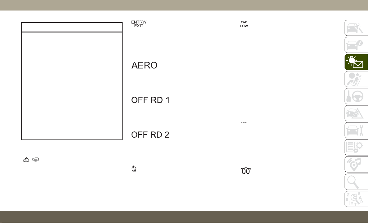
CAUTION!
The TPMS has been optimized for the
original equipment tires and wheels.
TPMS pressures and warning have been
established for the tire size equipped on
your vehicle. Undesirable system opera-
tion or sensor damage may result when
using replacement equipment that is not
of the same size, type, and/or style. After-
market wheels can cause sensor damage.
Using aftermarket tire sealants may cause
the Tire Pressure Monitoring System
(TPMS) sensor to become inoperable.
After using an aftermarket tire sealant it is
recommended that you take your vehicle to
your authorized dealer to have your sensor
function checked.
Yellow Indicator Lights
— Air Suspension Active Indicator
Light — If Equipped
This light will illuminate when the air suspen-
sion system is actively adjusting the ride height.
— Air Suspension Entry/Exit
Indicator Light— If Equipped
T
his light will illuminate when the vehicle is
automatically lowered from ride height position
downward for easy entry and exit of the vehicle.
— Air Suspension Aerody-
namic Height Indicator Light— If Equipped
This light will illuminate when the air suspen-
sion system is set to the Aerodynamic setting.
— Air Suspension Off-
Road 1 Indicator Light — If Equipped
This light will illuminate when the air suspen-
sion system is set to the Off-Road 1 setting.
— Air Suspension Off-
Road 2 Indicator Light — If Equipped
This light will illuminate when the air suspen-
sion system is set to the Off-Road 2 setting.
— Forward Collision Warning Off
Indicator Light — If Equipped
This indicator light illuminates to indicate
that Forward Collision Warning is off.
— 4WD Low Indicator Light —
If Equipped
This light alerts the driver that the vehicle is
in the four-wheel drive LOW mode. The front
and rear driveshafts are mechanically locked
together forcing the front and rear wheels to
rotate at the same speed. Low range provides
a greater gear reduction ratio to provide in-
creased torque at the wheels.
Refer to “Four-Wheel Drive Operation — If
Equipped” in “Starting And Operating” for
further information on four-wheel drive op-
eration and proper use.
— NEUTRAL Indicator Light —
If Equipped
This light alerts the driver that the 4WD
power transfer case is in the NEUTRAL mode
and the front and rear driveshafts are disen-
gaged from the powertrain.
— Wait To Start Light — If Equipped
This indicator light will illuminate for ap-
proximately two seconds when the ignition is
turned to the RUN position. Its duration may
81
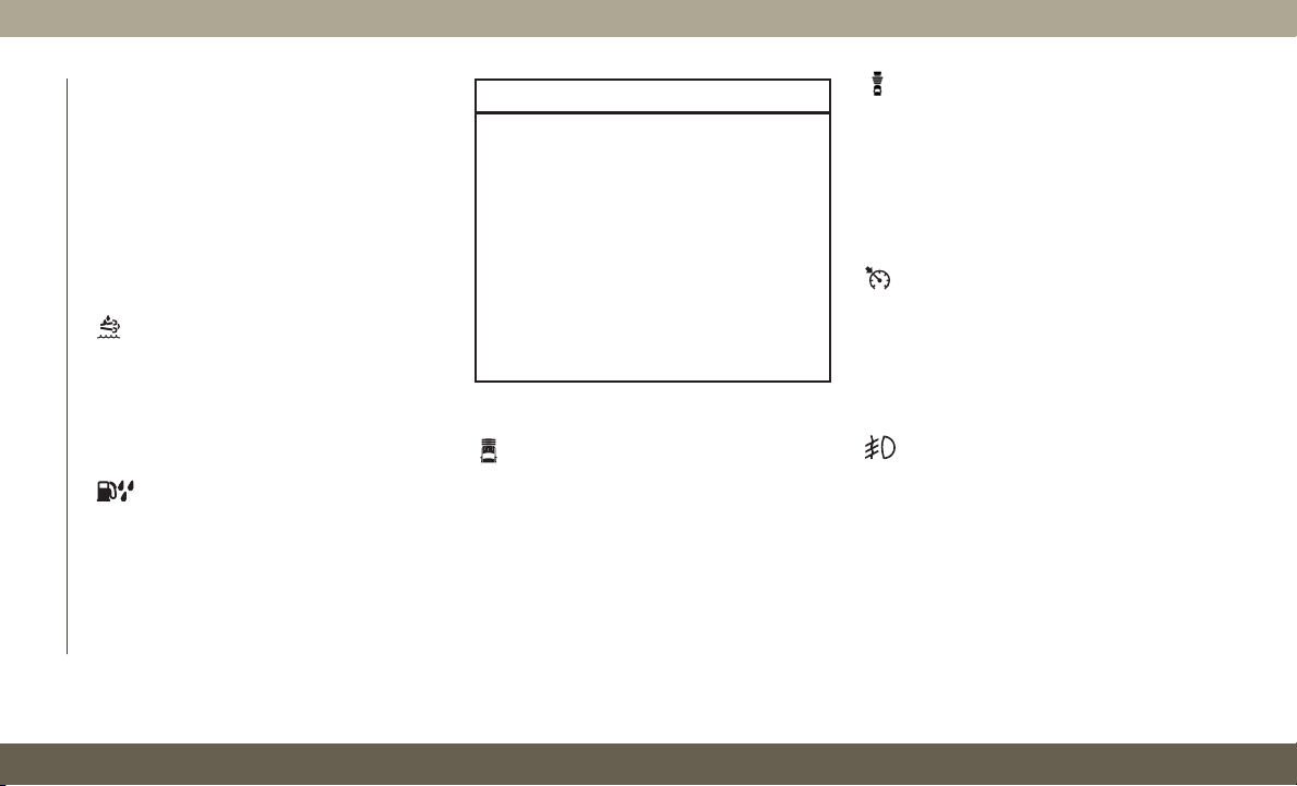
be longer based on colder operating condi-
tions. Vehicle will not initiate start until tell-
tale is no longer displayed.
Refer to “Starting The Engine” in “Starting
And Operating” for further information.
NOTE:
The “Wait To Start” telltale may not illumi-
nate if the intake manifold temperature is
warm enough.
— Low Diesel Exhaust Fluid (DEF) Indi-
cator Light — If Equipped
The Low Diesel Exhaust Fluid (DEF) Indicator
will illuminate if the vehicle is low on Diesel
Exhaust Fluid (DEF). Refer to “Starting And
Operating” for further information.
— Water In Fuel Indicator Light —
If Equipped
The “Water In Fuel Indicator Light” will illu-
minate when there is water detected in the
fuel filter. If this light remains on, DO NOT
start the vehicle before you drain the water
from the fuel filter to prevent engine damage,
and please see an authorized dealer.
CAUTION!
The presence of water in the fuel system
circuit may cause severe damage to the
injection system and irregular engine op-
eration. If the indicator light is illumi-
nated, contact an authorized dealer as
soon as possible to bleed the system. If the
above indications come on immediately
after refuelling, water has probably been
poured into the tank: switch the engine off
immediately and contact an authorized
dealer.
Green Indicator Lights
— Adaptive Cruise Control (ACC) Set
With No Target Detected Indicator Light —
If Equipped
This light will turn on when the Adaptive
Cruise Control is set and there is no target
vehicle detected. Refer to "Adaptive Cruise
Control (ACC) — If Equipped" in "Starting
And Operating" for further information.
— Adaptive Cruise Control (ACC) Set
With Target Light — If Equipped
This will display when the ACC is set and a
target vehicle is detected. Refer to “Adaptive
Cruise Control (ACC) — If Equipped” in
“Starting And Operating” for further informa-
tion.
— Cruise Control Set Indicator Light
— If Equipped
This indicator light will illuminate when the
cruise control is set to the desired speed.
Refer to “Speed Control” in “Starting And
Operating” for further information.
— Front Fog Indicator Light — If
Equipped
This indicator light will illuminate when the
front fog lights are on.
GETTING TO KNOW YOUR INSTRUMENT PANEL
82

— LaneSense Indicator Light — If
Equipped
T
he LaneSense indicator light illuminates solid
green when both lane markings have been
detected and the system is “armed” and ready
to provide visual and torque warnings if an
unintentional lane departure occurs.
Refer to “LaneSense — If Equipped" in “Start-
ing And Operating” for further information.
— Park/Headlight On Indicator Light
This indicator light will illuminate when the
park lights or headlights are turned on.
— Snow Mode SRT Indicator Light
This light will turn on when Snow Mode is
active.
Refer to “Selec-Track” in “Starting And Op-
erating” for further information.
— Sport Mode Indicator Light
This light will turn on when Sport Mode is
active.
— Sport Mode SRT Indicator Light
This light will turn on when Sport Mode is
active.
Refer to “Selec-Track” in “Starting And Op-
erating” for further information.
— Stop/Start Active Indicator Light —
If Equipped
This indicator light will illuminate when the
Stop/Start function is in “Autostop” mode.
— Tow Mode SRT Indicator Light
This light will turn on when Tow Mode is
active.
Refer to “Selec-Track” in “Starting And Op-
erating” for further information.
— Track Mode SRT Indicator Light
This light will turn on when Track Mode is
active.
Refer to “Selec-Track” in “Starting And Op-
erating” for further information.
— Turn Signal Indicator Lights
When the left or right turn signal is activated,
the turn signal indicator will flash indepen-
dently and the corresponding exterior turn
signal lamps will flash. Turn signals can be
activated when the multifunction lever is
moved down (left) or up (right).
NOTE:
• A continuous chime will sound if the ve-
hicle is driven more than 1 mile (1.6 km)
with either turn signal on.
• Check for an inoperative outside light bulb
if either indicator flashes at a rapid rate.
White Indicator Lights
— Adaptive Cruise Control (ACC) Ready
Light — If Equipped
This light will turn on when the vehicle
equipped with Adaptive Cruise Control (ACC)
has been turned on, but not set. Refer to
“Adaptive Cruise Control (ACC) — If
Equipped” in “Starting And Operating” for
further information.
83

— Custom Mode SRT Indicator Light
This light will turn on when Custom Mode
SRT is active.
Refer to “Selec-Track” in “Starting And Op-
erating” for further information.
— Hill Descent Control (HDC) Indicator
Light — If Equipped
This indicator shows when the Hill Descent
Control (HDC) feature is turned on. The lamp
will be on solid when HDC is armed. HDC can
only be armed when the transfer case is in the
“4WD LOW” position and the vehicle speed
is less then 30 mph (48 km/h). If these
conditions are not met while attempting to
use the HDC feature, the HDC indicator light
will flash on/off.
— LaneSense Indicator Light —
If Equipped
When the LaneSense system is ON, but not
armed, the LaneSense indicator light illumi-
nates solid white. This occurs when only left,
right, or neither lane line has been detected.
If a single lane line is detected, the system is
ready to provide only visual warnings if an
unintentional lane departure occurs on the
detected lane line.
Refer to “LaneSense — If Equipped" in
“Starting And Operating” for further informa-
tion.
— SRT Speed Warning Indicator
Light — If Equipped
When Set Speed Warning is turned on, the
speed warning telltale will illuminate in the
instrument cluster with a number matching
the set speed. When the set speed is ex-
ceeded, the indication will light up yellow
and flash along with a continuous chime.
Speed Warning can be turned on and off in
the instrument cluster display.
Refer to “Instrument Cluster Display” in
“Getting To Know Your Instrument Panel” in
the Owner’s Manual for further information.
The number “55” is only an example of a
speed that can be set.
— Cruise Control Ready Indicator
Light
This light will turn on when the speed control
has been turned on, but not set. Refer to
“Speed Control — If Equipped” in “Starting
And Operating” for further information.
— Selec Speed Control Indicator
Light — If Equipped
This light will turn on when “Selec Speed
Control” is activated.
To activate “Selec Speed Control”, assure the
vehicle is Four Wheel Drive Low (4WD) and
push the button on the Instrument Panel.
NOTE:
If the vehicle is not in 4WD Low, “To Enter
Selec-Speed Shift to 4WD Low” will appear
in the instrument cluster display.
— Valet Mode SRT Indicator
Light
This light will turn on when Valet Mode is
active.
GETTING TO KNOW YOUR INSTRUMENT PANEL
84
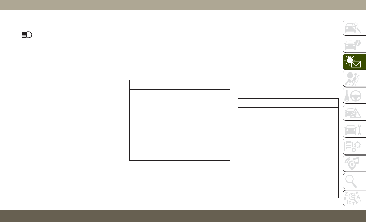
Blue Indicator Lights
— High Beam Indicator Light
This indicator light will illuminate to indicate
that the high beam headlights are on. With
the low beams activated, push the multifunc-
tion lever forward (toward the front of the
vehicle) to turn on the high beams. Pull the
multifunction lever rearward (toward the rear
of the vehicle) to turn off the high beams. If
the high beams are off, pull the lever toward
you for a temporary high beam on, "flash to
pass" scenario.
ONBOARD DIAGNOSTIC
SYSTEM — OBD II
Your vehicle is equipped with a sophisticated
Onboard Diagnostic system called OBD II.
This system monitors the performance of the
emissions, engine, and transmission control
systems. When these systems are operating
properly, your vehicle will provide excellent
performance and fuel economy, as well as
engine emissions well within current govern-
ment regulations.
If any of these systems require service, the
OBD II system will turn on the Malfunction
Indicator Light (MIL). It will also store diag-
nostic codes and other information to assist
your service technician in making repairs.
Although your vehicle will usually be drivable
and not need towing, see an authorized
dealer for service as soon as possible.
CAUTION!
• Prolonged driving with the MIL on could
cause further damage to the emission
control system. It could also affect fuel
economy and driveability. The vehicle
must be serviced before any emissions
tests can be performed.
• If the MIL is flashing while the vehicle is
running, severe catalytic converter dam-
age and power loss will soon occur. Im-
mediate service is required.
Onboard Diagnostic System (OBD II)
Cybersecurity
Your vehicle is required to have an Onboard
Diagnostic system (OBD II) and a connection
port to allow access to information related to
the performance of your emissions controls.
Authorized service technicians may need to
access this information to assist with the
diagnosis and service of your vehicle and
emissions system.
WARNING!
• ONLY an authorized service technician
should connect equipment to the OBD II
connection port in order to read the VIN,
diagnose, or service your vehicle.
• If unauthorized equipment is connected
to the OBD II connection port, such as a
driver-behavior tracking device, it may:
• Be possible that vehicle systems,
including safety related systems,
could be impaired or a loss of ve-
hicle control could occur that may
result in an accident involving seri-
ous injury or death.
85

WARNING!
• Access, or allow others to access,
information stored in your vehicle
systems, including personal infor-
mation.
For further information, refer to “Cybersecu-
rity” in “Multimedia”.
EMISSIONS INSPECTION
AND MAINTENANCE
PROGRAMS
In some localities, it may be a legal require-
ment to pass an inspection of your vehicle's
emissions control system. Failure to pass
could prevent vehicle registration.
For states that require an Inspec-
tion and Maintenance (I/M), this
check verifies the “Malfunction
Indicator Light (MIL)” is functioning and is
not on when the engine is running, and that
the OBD II system is ready for testing.
N
ormally, the OBD II system will be ready. The
OBD II system may
not be ready if your vehicle
was recently serviced, recently had a dead
battery or a battery replacement. If the
OBD II system should be determined not
ready for the I/M test, your vehicle may fail
the test.
Your vehicle has a simple ignition actuated
test, which you can use prior to going to the
test station. To check if your vehicle's OBD II
system is ready, you must do the following:
1. Cycle the ignition switch to the ON posi-
tion, but do not crank or start the engine.
NOTE:
If you crank or start the engine, you will
have to start this test over.
2. As soon as you cycle the ignition switch to
the ON position, you will see the “Mal-
function Indicator Light (MIL)” symbol
come on as part of a normal bulb check.
3. Approximately 15 seconds later, one of
two things will happen:
• The MIL will flash for about ten seconds
and then return to being fully illuminated
until you turn OFF the ignition or start the
engine. This means that your vehicle's
OBD II system is not ready and you should
not proceed to the I/M station.
• The MIL will not flash at all and will remain
fully illuminated until you place the igni-
tion in the off position or start the engine.
This means that your vehicle's OBD II sys-
tem is ready and you can proceed to the I/M
station.
If your OBD II system is not ready, you should
see an authorized dealer or repair facility.
If your vehicle was recently serviced or had a
battery failure or replacement, you may need
to do nothing more than drive your vehicle as
you normally would in order for your OBD II
system to update. A recheck with the above
test routine may then indicate that the sys-
tem is now ready.
Regardless of whether your vehicle's OBD II
system is ready or not, if the MIL is illumi-
nated during normal vehicle operation you
should have your vehicle serviced before go-
ing to the I/M station. The I/M station can fail
your vehicle because the MIL is on with the
engine running.
GETTING TO KNOW YOUR INSTRUMENT PANEL
86
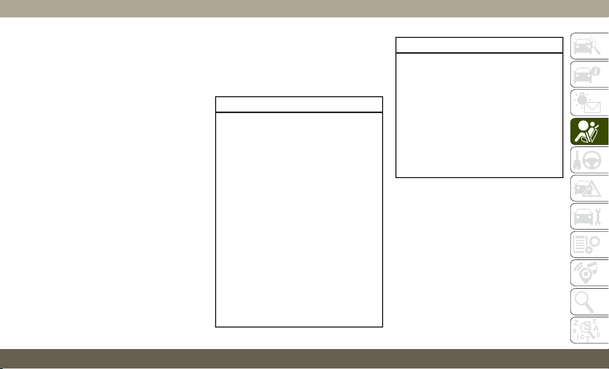
SAFETY FEATURES
Anti-Lock Brake System (ABS)
The Anti-Lock Brake System (ABS) provides
increased vehicle stability and brake perfor-
mance under most braking conditions. The
system automatically prevents wheel lock,
and enhances vehicle control during braking.
The ABS performs a self-check cycle to en-
sure that the ABS is working properly each
time the vehicle is started and driven. During
this self-check, you may hear a slight clicking
sound as well as some related motor noises.
ABS is activated during braking when the
system detects one or more wheels begin to
lock. Road conditions such as ice, snow,
gravel, bumps, railroad tracks, loose debris,
or panic stops may increase the likelihood of
ABS activation(s).
You also may experience the following when
ABS activates:
• The ABS motor noise (it may continue to
run for a short time after the stop).
• The clicking sound of solenoid valves.
• Brake pedal pulsations.
• A slight drop of the brake pedal at the end
of the stop.
These are all normal characteristics of ABS.
WARNING!
• The ABS contains sophisticated elec-
tronic equipment that may be suscep-
tible to interference caused by improp-
erly installed or high output radio
transmitting equipment. This interfer-
ence can cause possible loss of anti-lock
braking capability. Installation of such
equipment should be performed by
qualified professionals.
• Pumping of the Anti-Lock Brakes will
diminish their effectiveness and may
lead to a collision. Pumping makes the
stopping distance longer. Just press
firmly on your brake pedal when you
need to slow down or stop.
• The ABS cannot prevent the natural laws
of physics from acting on the vehicle,
nor can it increase braking or steering
efficiency beyond that afforded by the
WARNING!
condition of the vehicle brakes and tires
or the traction afforded.
• The ABS cannot prevent collisions, in-
cluding those resulting from excessive
speed in turns, following another vehicle
too closely, or hydroplaning.
• The capabilities of an ABS equipped
vehicle must never be exploited in a
reckless or dangerous manner that could
jeopardize the user’s safety or the safety
of others.
ABS is designed to function with the OEM
tires. Modification may result in degraded
ABS performance.
Anti-Lock Brake Warning Light
The yellow “Anti-Lock Brake Warning Light”
will turn on when the ignition is turned to the
ON/RUN mode and may stay on for as long as
four seconds.
If the “Anti-Lock Brake Warning Light” re-
mains on or comes on while driving, it indi-
cates that the anti-lock portion of the brake
87

system is not functioning and that service is
required. However, the conventional brake
system will continue to operate normally if
the “Anti-Lock Brake Warning Light” is on.
If the “Anti-Lock Brake Warning Light” is on,
the brake system should be serviced as soon
as possible to restore the benefits of anti-lock
brakes. If the “Anti-Lock Brake Warning
Light” does not come on when the ignition is
turned to the ON/RUN mode, have the light
repaired as soon as possible.
Electronic Brake Control System
Your vehicle is equipped with an advanced
Electronic Brake Control system (EBC). This
system includes Electronic Brake Force Dis-
tribution (EBD), Anti-Lock Brake System
(ABS), Brake Assist System (BAS), Hill Start
Assist (HSA), Traction Control System (TCS),
Electronic Stability Control (ESC), and Elec-
tronic Roll Mitigation (ERM). These systems
work together to enhance both vehicle stabil-
ity and control in various driving conditions.
Y
our vehicle may also be equipped with Trailer
Sway Control (TSC), Ready Alert Braking
(RAB), Rain Brake Support (RBS), Dynamic
Steering Torque (DST), Hill Descent Control
(HDC), and Selec-Speed Control (SSC).
Your vehicle may also be equipped with
Trailer Sway Control (TSC), Ready Alert Brak-
ing (RAB), Rain Brake Support (RBS), and-
Dynamic Steering Torque (DST).
Electronic Brake Force Distribution (EBD)
This function manages the distribution of the
braking torque between the front and rear
axles by limiting braking pressure to the rear
axle. This is done to prevent overslip of the
rear wheels to avoid vehicle instability, and to
prevent the rear axle from entering ABS be-
fore the front axle.
Brake System Warning Light
The red “Brake System Warning Light” will
turn on when the ignition is turned to the
ON/RUN mode and may stay on for as long as
four seconds.
If the “Brake System Warning Light” remains
on or comes on while driving, it indicates that
the brake system is not functioning properly
and that immediate service is required. If the
“Brake System Warning Light” does not
come on when the ignition is turned to the
ON/RUN mode, have the light repaired as
soon as possible.
Brake Assist System (BAS)
The BAS is designed to optimize the vehicle’s
braking capability during emergency braking
maneuvers. The system detects an emer-
gency braking situation by sensing the rate
and amount of brake application and then
applies optimum pressure to the brakes. This
can help reduce braking distances. The BAS
complements the anti-lock brake system
(ABS). Applying the brakes very quickly re-
sults in the best BAS assistance. To receive
the benefit of the system, you must apply
continuous braking pressure during the stop-
ping sequence, (do not “pump” the brakes).
Do not reduce brake pedal pressure unless
braking is no longer desired. Once the brake
pedal is released, the BAS is deactivated.
SAFETY
88
WARNING!
The Brake Assist System (BAS) cannot
prevent the natural laws of physics from
acting on the vehicle, nor can it increase
the traction afforded by prevailing road
conditions. BAS cannot prevent collisions,
including those resulting from excessive
speed in turns, driving on very slippery
surfaces, or hydroplaning. The capabilities
of a BAS-equipped vehicle must never be
exploited in a reckless or dangerous man-
ner, which could jeopardize the user's
safety or the safety of others.
Hill Start Assist (HSA)
The HSA system is designed to mitigate roll
back from a complete stop while on an in-
cline. If the driver releases the brake while
stopped on an incline, HSA will continue to
hold the brake pressure for a short period. If
the driver does not apply the throttle before
this time expires, the system will release
brake pressure and the vehicle will roll down
the hill as normal.
The following conditions must be met in
order for HSA to activate:
• The feature must be enabled.
• The vehicle must be stopped.
• Park brake must be off.
• Driver door must be closed.
• The vehicle must be on a sufficient grade.
• The gear selection must match vehicle up-
hill direction (i.e., vehicle facing uphill is in
forward gear; vehicle backing uphill is in
REVERSE gear).
• HSA will work in REVERSE gear and all
forward gears. The system will not activate
if the transmission is in PARK or NEU-
TRAL. For vehicles equipped with a manual
transmission, if the clutch is pressed, HSA
will remain active.
WARNING!
There may be situations where the Hill
Start Assist (HSA) will not activate and
slight rolling may occur, such as on minor
hills or with a loaded vehicle, or while
pulling a trailer. HSA is not a substitute for
WARNING!
active driving involvement. It is always the
driver’s responsibility to be attentive to
distance to other vehicles, people, and
objects, and most importantly brake op-
eration to ensure safe operation of the
vehicle under all road conditions. Your
complete attention is always required
while driving to maintain safe control of
your vehicle. Failure to follow these warn-
ings can result in a collision or serious
personal injury.
Disabling And Enabling HSA
This feature can be turned on or turned off. To
change the current setting, proceed as fol-
lows:
• If disabling HSA using your instrument
cluster display, refer to “Instrument Cluster
Display” in “Getting To Know Your Instru-
ment Panel” for further information.
• If disabling HSA using Uconnect Settings,
refer to “Uconnect Settings” in “Multime-
dia” for further information.
89

For vehicles not equipped with an instrument
cluster display, perform the following steps:
1. Center the steering wheel (front wheels
pointing straight forward).
2. Shift the transmission into PARK.
3. Apply the parking brake.
4. Start the engine.
5. Rotate the steering wheel slightly more
than one-half turn to the left.
6. Push the “ESC Off” button located in the
lower switch bank below the climate con-
trol four times within 20 seconds. The
“ESC Off Indicator Light” should turn on
and turn off two times.
7. Rotate the steering wheel back to center
and then an additional slightly more than
one-half turn to the right.
8. Turn the ignition to the OFF mode and
then back to ON. If the sequence was
completed properly, the “ESC Off Indica-
tor Light” will blink several times to con-
firm HSA is disabled.
9. Repeat these steps if you want to return
this feature to its previous setting.
Towing With HSA
HSA will also provide assistance to mitigate
roll back while towing a trailer.
WARNING!
• If you use a trailer brake controller with
your trailer, the trailer brakes may be
activated and deactivated with the brake
switch. If so, there may not be enough
brake pressure to hold both the vehicle
and the trailer on a hill when the brake
pedal is released. In order to avoid roll-
ing down an incline while resuming ac-
celeration, manually activate the trailer
brake or apply more vehicle brake pres-
sure prior to releasing the brake pedal.
• HSA is not a parking brake. Always apply
the parking brake fully when exiting your
vehicle. Also, be certain to place the
transmission in PARK.
• Failure to follow these warnings can re-
sult in a collision or serious personal
injury.
Traction Control System (TCS)
This system monitors the amount of wheel spin
of each of the driven wheels. If wheel spin is
detected, the TCS may apply brake pressure to
the spinning wheel(s) and/or reduce engine
power to provide enhanced acceleration and
stability. A feature of the TCS, Brake Limited
Differential (BLD), functions similar to a lim-
ited slip differential and controls the wheel
spin across a driven axle. If one wheel on a
driven axle is spinning faster than the other,
the system will apply the brake of the spinning
wheel. This will allow more engine power to be
applied to the wheel that is not spinning. BLD
may remain enabled even if TCS and ESC are
in a reduced mode.
Electronic Stability Control (ESC)
This system enhances directional control and
stability of the vehicle under various driving
conditions. ESC corrects for oversteering or
understeering of the vehicle by applying the
brake of the appropriate wheel(s) to assist in
counteracting the oversteer or understeer
condition. Engine power may also be reduced
to help the vehicle maintain the desired path.
SAFETY
90

ESC uses sensors in the vehicle to determine
the vehicle path intended by the driver and
compares it to the actual path of the vehicle.
When the actual path does not match the
intended path, ESC applies the brake of the
appropriate wheel to assist in counteracting
the oversteer or understeer condition.
• Oversteer — when the vehicle is turning
more than appropriate for the steering
wheel position.
• Understeer — when the vehicle is turning
less than appropriate for the steering wheel
position.
The “ESC Activation/Malfunction Indicator
Light” located in the instrument cluster will
start to flash as soon as the ESC system
becomes active. The “ESC Activation/
Malfunction Indicator Light” also flashes
when the TCS is active. If the “ESC
Activation/Malfunction Indicator Light” be-
gins to flash during acceleration, ease up on
the accelerator and apply as little throttle as
possible. Be sure to adapt your speed and
driving to the prevailing road conditions.
WARNING!
• Electronic Stability Control (ESC) can-
not prevent the natural laws of physics
from acting on the vehicle, nor can it
increase the traction afforded by prevail-
ing road conditions. ESC cannot prevent
accidents, including those resulting
from excessive speed in turns, driving on
very slippery surfaces, or hydroplaning.
ESC also cannot prevent accidents re-
sulting from loss of vehicle control due
to inappropriate driver input for the con-
ditions. Only a safe, attentive, and skill-
ful driver can prevent accidents. The
capabilities of an ESC equipped vehicle
must never be exploited in a reckless or
dangerous manner which could jeopar-
dize the user’s safety or the safety of
others.
• Vehicle modifications, or failure to prop-
erly maintain your vehicle, may change
the handling characteristics of your ve-
hicle, and may negatively affect the per-
formance of the ESC system. Changes to
the steering system, suspension, brak-
WARNING!
ing system, tire type and size or wheel
size may adversely affect ESC perfor-
mance. Improperly inflated and un-
evenly worn tires may also degrade ESC
performance. Any vehicle modification
or poor vehicle maintenance that re-
duces the effectiveness of the ESC sys-
tem can increase the risk of loss of
vehicle control, vehicle rollover, per-
sonal injury and death.
ESC Operating Modes
NOTE:
Depending upon model and mode of opera-
tion, the ESC system may have multiple op-
erating modes.
ESC On
This is the normal operating mode for the
ESC. Whenever the vehicle is started, the
ESC system will be in this mode. This mode
91

should be used for most driving conditions.
Alternate ESC modes should only be used for
specific reasons as noted in the following
paragraphs.
Partial Off
The “Partial Off” mode is intended for times
when a more spirited driving experience is
desired. This mode may modify TCS and ESC
thresholds for activation, which allows for
more wheel spin than normally allowed. This
mode may be useful if the vehicle becomes
stuck.
To enter the “Partial Off” mode, momentarily
push the “ESC Off” switch and the “ESC Off
Indicator Light” will illuminate. To turn the
ESC on again, momentarily push the “ESC
Off” switch and the “ESC Off Indicator Light”
will turn off.
NOTE:
For vehicles with multiple partial ESC modes
a momentary button push will toggle the ESC
mode. Multiple momentary button pushed
may be required to return to ESC On.
WARNING!
•
When in “Partial Off” mode, the TCS
functionality of ESC, (except for the lim-
ited slip feature described in the TCS
section), has been disabled and the “ESC
Off Indicator Light” will be illuminated.
When in “Partial Off” mode, the engine
power reduction feature of TCS is dis-
abled, and the enhanced vehicle stability
offered by the ESC system is reduced.
• Trailer Sway control (TSC) is disabled
when the ESC system is in the “Partial
Off” mode.
Full Off — If Equipped
This mode is intended for off-highway or
off-road use only and should not be used on
any public roadways. In this mode, TCS and
ESC features are turned OFF. To enter the
“Full Off” mode, push and hold the “ESC
Off” switch for five seconds while the vehicle
is stopped with the engine running. After five
seconds, a chime will sound, the “ESC Off
Indicator Light” will illuminate, and the
“ESC OFF” message will display in the in-
strument cluster. To turn ESC ON again,
momentarily push the “ESC Off” switch.
NOTE:
System may switch from ESC “Full Off” to
“Partial Off” mode when vehicle exceeds a
predetermined speed. When the vehicle
speed slows below the predetermined speed
the system will return to ESC “Full Off”.
“Full Off” can only be achieved in Track
Mode if so equipped.
ESC modes may also be affected by drive
modes if so equipped.
WARNING!
• In the ESC “Full Off” mode, the engine
torque reduction and stability features
are disabled. Therefore, enhanced ve-
hicle stability offered by the ESC system
is unavailable. In an emergency evasive
maneuver, the ESC system will not en-
gage to assist in maintaining stability.
ESC “Full Off” mode is intended for
off-highway or off-road use only.
SAFETY
92
WARNING!
• The Electronic Stability Control (ESC)
cannot prevent the natural laws of phys-
ics from acting on the vehicle, nor can it
increase the traction afforded by prevail-
ing road conditions. ESC cannot prevent
all accidents, including those resulting
from excessive speed in turns, driving on
very slippery surfaces, or hydroplaning.
ESC also cannot prevent collisions.
ESC Activation/Malfunction Indicator Light
And ESC OFF Indicator Light
The “ESC Activation/Malfunction
Indicator Light” in the instrument
cluster will come on when the
ignition is turned to the ON mode.
It should go out with the engine
running. If the “ESC Activation/Malfunction
Indicator Light” comes on continuously with
the engine running, a malfunction has been
detected in the ESC system. If this light
remains on after several ignition cycles, and
the vehicle has been driven several miles
(kilometers) at speeds greater than 30 mph
(48 km/h), see an authorized dealer as soon
as possible to have the problem diagnosed
and corrected.
The “ESC Activation/Malfunction Indicator
Light” (located in the instrument cluster)
starts to flash as soon as the tires lose trac-
tion and the ESC system becomes active.
The “ESC Activation/Malfunction Indicator
Light” also flashes when TCS is active.
If the “ESC Activation/Malfunction Indicator
Light” begins to flash during acceleration,
ease up on the accelerator and apply as little
throttle as possible. Be sure to adapt your
speed and driving to the prevailing road con-
ditions.
NOTE:
• The “ESC Activation/Malfunction Indicator
Light” and the “ESC OFF Indicator Light”
come on momentarily each time the igni-
tion is turned ON.
• Each time the ignition is turned ON, the
ESC system will be on even if it was turned
off previously.
• The ESC system will make buzzing or click-
ing sounds when it is active. This is normal;
the sounds will stop when ESC becomes
inactive following the maneuver that
caused the ESC activation.
The “ESC OFF Indicator Light” indi-
cates the customer has elected to
have the Electronic Stability Control
(ESC) in a reduced mode.
Electronic Roll Mitigation (ERM)
T
his system anticipates the potential for wheel
lift by monitoring the driver’s steering wheel
input and the speed of the vehicle. When ERM
determines that the rate of change of the
steering wheel angle and vehicle’s speed are
sufficient to potentially cause wheel lift, it then
applies the appropriate brake and may also
reduce engine power to lessen the chance that
wheel lift will occur. ERM can only reduce the
chance of wheel lift occurring during severe or
evasive driving maneuvers; it cannot prevent
wheel lift due to other factors, such as road
conditions, leaving the roadway, or striking
objects or other vehicles.
93

NOTE:
ERM is disabled anytime the ESC is in “Full
Off” mode (if equipped). Refer to “Electronic
Stability Control (ESC)” in this section for a
complete explanation of the available ESC
modes.
WARNING!
Many factors, such as vehicle loading,
road conditions and driving conditions,
influence the chance that wheel lift or
rollover may occur. ERM cannot prevent
all wheel lift or roll overs, especially those
that involve leaving the roadway or striking
objects or other vehicles. The capabilities
of an ERM-equipped vehicle must never
be exploited in a reckless or dangerous
manner which could jeopardize the user's
safety or the safety of others.
Trailer Sway Control (TSC)
T
SC uses sensors in the vehicle to recognize an
excessively swaying trailer and will take the
appropriate actions to attempt to stop the sway.
TSC will become active automatically once an
excessively swaying trailer is recognized.
NOTE:
TSC cannot stop all trailers from swaying.
Always use caution when towing a trailer and
follow the trailer tongue weight recommenda-
tions. Refer to “Trailer Towing” in “Starting
And Operating” for further information.
When TSC is functioning, the “ESC
Activation/Malfunction Indicator Light” will
flash, the engine power may be reduced and
you may feel the brakes being applied to
individual wheels to attempt to stop the
trailer from swaying. TSC is disabled when
the ESC system is in the “Partial Off” or “Full
Off” modes.
WARNING!
If TSC activates while driving, slow the
vehicle down, stop at the nearest safe
location, and adjust the trailer load to
eliminate trailer sway.
Ready Alert Braking (RAB)
Ready Alert Braking may reduce the time
required to reach full braking during emer-
gency braking situations. It anticipates when
an emergency braking situation may occur by
monitoring how fast the throttle is released by
the driver. The EBC will prepare the brake
system for a panic stop.
Rain Brake Support (RBS)
Rain Brake Support may improve braking
performance in wet conditions. It will periodi-
cally apply a small amount of brake pressure
to remove any water buildup on the front
brake rotors. It functions when the wind-
shield wipers are in LO or HI speed. When
Rain Brake Support is active, there is no
notification to the driver and no driver inter-
action is required.
Dynamic Steering Torque (DST)
Dynamic Steering Torque is a feature of the
ESC and Electric Power Steering (EPS) mod-
ules that provides torque at the steering
wheel for certain driving conditions in which
the ESC module is detecting vehicle instabil-
ity. The torque that the steering wheel re-
ceives is only meant to help the driver realize
optimal steering behavior in order to reach/
SAFETY
94

maintain vehicle stability. The only notifica-
tion the driver receives that the feature is
active is the torque applied to the steering
wheel.
NOTE:
T
he DST feature is only meant to help the
driver realize the correct course of action
through small torques on the steering wheel,
which means the effectiveness of the DST
feature is highly dependent on the driver’s
sensitivity and overall reaction to the applied
torque. It is very important to realize that
this feature will not steer the vehicle, meaning
the driver is still responsible for steering the
vehicle.
Hill Descent Control (HDC) — If Equipped
HDC is intended for low speed off road driving
while in 4WD Low Range. HDC maintains
vehicle speed while descending hills during
various driving situations. HDC controls ve-
hicle speed by actively controlling the brakes.
HDC Has Three States:
1. Off (feature is not enabled and will not
activate).
2. Enabled (feature is enabled and ready but
activation conditions are not met, or driver
is actively overriding with brake or throttle
application).
3. Active (feature is enabled and actively
controlling vehicle speed).
Enabling HDC
HDC is enabled by pushing the HDC switch,
but the following conditions must also be met
to enable HDC:
• Driveline is in 4WD Low Range.
• Vehicle speed is below 5 mph (8 km/h).
• Parking brake is released.
• Driver door is closed.
Activating HDC
Once HDC is enabled it will activate auto-
matically if driven down a grade of sufficient
magnitude. The set speed for HDC is select-
able by the driver, and can be adjusted by
using the gear shift +/-. The following sum-
marizes the HDC set speeds:
HDC Target Set Speeds
• P = No set speed. HDC may be enabled but
will not activate.
• R = 0.6 mph (1 km/h)
• N = 1.2 mph (2 km/h)
• D = 0.6 mph (1 km/h)
• 1st = 0.6 mph (1 km/h)
• 2nd = 1.2 mph (2 km/h)
• 3rd = 1.8 mph (3 km/h)
• 4th = 2.5 mph (4 km/h)
• 5th = 3.1 mph (5 km/h)
• 6th = 3.7 mph (6 km/h)
• 7th = 4.3 mph (7 km/h)
• 8th = 5.0 mph (8 km/h)
• 9th = 5.6 mph (9 km/h) – If Equipped
95

NOTE:
During HDC the +/- shifter input is used for
HDC target speed selection, but will not af-
fect the gear chosen by the transmission.
When actively controlling HDC the transmis-
sion will shift appropriately for the driver-
selected set speed and corresponding driving
conditions.
Driver Override
The driver may override HDC activation with
throttle or brake application at anytime.
Deactivating HDC
HDC will be deactivated but remain available
if any of the following conditions occur:
• Driver overrides HDC set speed with throttle
or brake application.
• Vehicle speed exceeds 20 mph (32 km/h)
but remains below 40 mph (64 km/h).
• Vehicle is on a downhill grade of insuffi-
cient magnitude, is on level ground, or is on
an uphill grade.
• Vehicle is shifted to park.
Disabling HDC
HDC will be deactivated and disabled if any
of the following conditions occur:
• The driver pushes the HDC switch.
• The driveline is shifted out of 4WD Low
Range.
• The parking brake is applied.
• Driver door opens.
• The vehicle is driven greater than 20 mph
(32 km/h) for greater than 70 seconds.
• The vehicle is driven greater than 40 mph
(64 km/h) (HDC exits immediately).
• HDC detects excessive brake temperature.
Feedback To The Driver
The instrument cluster has an HDC icon and
the HDC switch has an LED icon, which
offers feedback to the driver about the state
HDC is in.
• The cluster icon and switch lamp will illu-
minate and remain on solid when HDC is
enabled or activated. This is the normal
operating condition for HDC.
• The cluster icon and switch lamp will flash
for several seconds then extinguish when
the driver pushes the HDC switch but en-
able conditions are not met.
• The cluster icon and switch lamp will flash
for several seconds then extinguish when
HDC disables due to excess speed.
• The cluster icon and switch lamp will flash
when HDC deactivates due to overheated
brakes. The flashing will stop and HDC will
activate again once the brakes have cooled
sufficiently.
WARNING!
HDC is only intended to assist the driver in
controlling vehicle speed when descend-
ing hills. The driver must remain attentive
to the driving conditions and is respon-
sible for maintaining a safe vehicle speed.
Selec Speed Control (SSC) — If Equipped
SSC is intended for off road driving in 4WD
Low Range only. SSC maintains vehicle
speed by actively controlling engine torque
and brakes.
SAFETY
96

SSC has three states:
1. Off (feature is not enabled and will not
activate).
2. Enabled (feature is enabled and ready but
activation conditions are not met, or driver
is actively overriding with brake or throttle
application).
3. Active (feature is enabled and actively
controlling vehicle speed).
Enabling SSC
SSC is enabled by pushing the SSC switch,
but the following conditions must also be met
to enable SSC:
• Driveline is in 4WD Low Range.
• Vehicle speed is below 5 mph (8 km/h).
• Parking brake is released.
• Driver door is closed.
• Driver is not applying throttle.
Activating SSC
Once SSC is enabled it will activate automati-
cally once the following conditions are met:
• Driver releases throttle.
• Driver releases brake.
•
Transmission is in any selection other than P.
• Vehicle speed is below 20 mph (32 km/h).
The set speed for SSC is selectable by the
driver, and can be adjusted by using the gear
shift +/-. Additionally, the SSC set speed may
be reduced when climbing a grade and the
level of set speed reduction depends on the
magnitude of grade. The following summa-
rizes the SSC set speeds:
SSC Target Set Speeds
• 1st = .6 mph (1 km/h)
• 2nd = 1.2 mph (2 km/h)
• 3rd = 1.8 mph (3 km/h)
• 4th = 2.5 mph (4 km/h)
• 5th = 3.1 mph (5 km/h)
• 6th = 3.7 mph (6 km/h)
• 7th = 4.3 mph (7 km/h)
• 8th = 5 mph (8 km/h)
• 9th = 5.6 mph (9 km/h) – If Equipped
• REVERSE = .6 mph (1 km/h)
• NEUTRAL = 1.2 mph (2 km/h)
• PARK = SSC remains enabled but not
active
NOTE:
• During SSC the +/- shifter input is used for
SSC target speed selection but will not
affect the gear chosen by the transmission.
While actively controlling SSC the trans-
mission will shift appropriately for the
driver-selected set speed and correspond-
ing driving conditions.
• SSC performance is influenced by the Ter-
rain Select mode. This difference may be
notable to the driver and may be perceived
as a varying level of aggressiveness.
Driver Override:
The driver may override SSC activation with
throttle or brake application at any time.
97

Deactivating SSC
SSC will be deactivated but remain available
if any of the following conditions occur:
• Driver overrides SSC set speed with throttle
or brake application.
• Vehicle speed exceeds 20 mph (32 km/h)
but remains below 40 mph (64 km/h).
• Vehicle is shifted to PARK.
Disabling SSC
SSC will deactivate and be disabled if any of
the following conditions occur:
• The driver pushes the SSC switch.
• The driveline is shifted out of 4WD Low
Range.
• The parking brake is applied.
• Driver door opens.
• The vehicle is driven greater than 20 mph
(32 km/h) for greater than 70 seconds.
• The vehicle is driven greater than 40 mph
(64 km/h) (SSC exits immediately).
Feedback To The Driver:
The instrument cluster has an SSC icon and
the SSC switch has an LED which offer feed-
back to the driver about the state SSC is in.
• The cluster icon and switch lamp will illu-
minate and remain on solid when SSC is
enabled or activated. This is the normal
operating condition for SSC.
• The cluster icon and switch lamp will flash
for several seconds then extinguish when
the driver pushes the SSC switch but en-
able conditions are not met.
• The cluster icon and switch lamp will flash
for several seconds then extinguish when
SSC disables due to excess speed.
• The cluster icon and switch lamp will flash
then extinguish when SSC deactivates due
to overheated brakes.
WARNING!
SSC is only intended to assist the driver in
controlling vehicle speed when driving in
off road conditions. The driver must re-
main attentive to the driving conditions
and is responsible for maintaining a safe
vehicle speed.
AUXILIARY DRIVING
SYSTEMS
Blind Spot Monitoring (BSM) —
If Equipped
The Blind Spot Monitoring (BSM) system
uses two radar sensors, located inside the
rear bumper fascia, to detect highway licens-
able vehicles (automobiles, trucks, motor-
cycles, etc.) that enter the blind spot zones
from the rear/front/side of the vehicle.
SAFETY
98
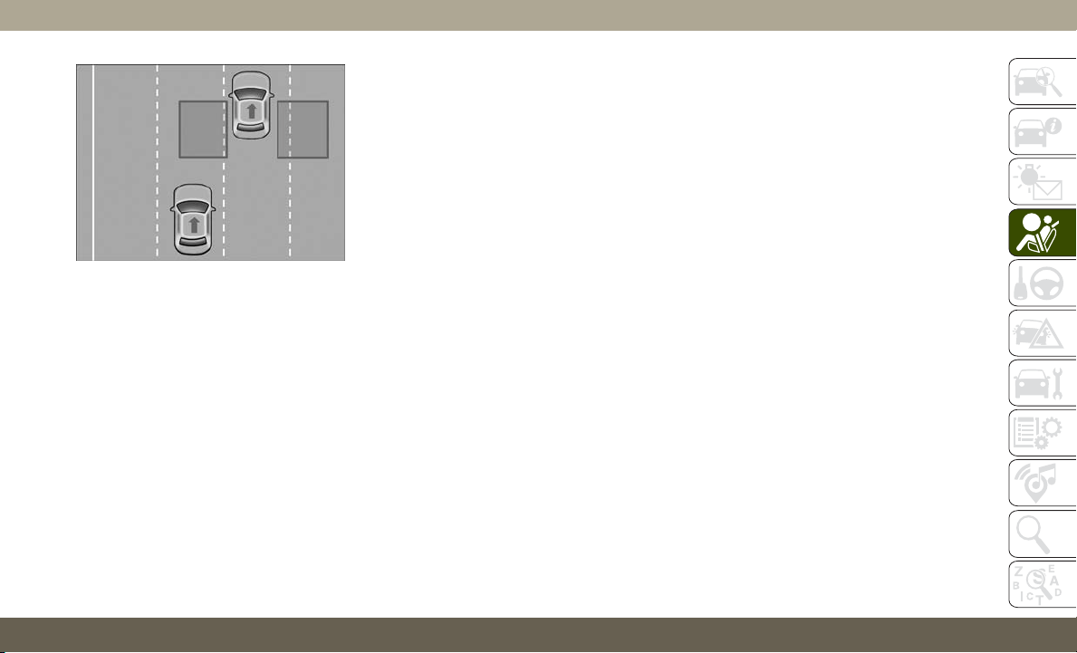
When the vehicle is started, the BSM warning
light will momentarily illuminate in both out-
side rear view mirrors to let the driver know
that the system is operational. The BSM
system sensors operate when the vehicle is in
any forward gear or REVERSE.
The BSM detection zone covers approxi-
mately one lane width on both sides of the
vehicle 12 ft (3.8 m). The zone length starts
at the side of the vehicle, near the B-Pillar,
and extends approximately 10 ft (3 m) be-
yond the rear bumper of the vehicle. The
BSM system monitors the detection zones
on both sides of the vehicle when the ve-
hicle speed reaches approximately 6 mph
(10 km/h) or higher and will alert the driver of
vehicles in these areas.
NOTE:
• The BSM system DOES NOT alert the driver
about rapidly approaching vehicles that are
outside the detection zones.
• The BSM system detection zone DOES NOT
change if your vehicle is towing a trailer.
Therefore, visually verify the adjacent lane
is clear for both your vehicle and trailer
before making a lane change. If the trailer
or other object (i.e., bicycle, sports equip-
ment) extends beyond the side of your ve-
hicle, this may result in random false de-
tections on the trailer, and false chimes
when the turn signal is used.
• The BSM system may experience drop outs
(blinking on and off) of the side mirror
Warning Indicator lamps when a motorcycle
or any small object remains at the side of
the vehicle for extended periods of time
(more than a couple of seconds).
The area on the rear fascia where the radar
sensors are located must remain free of snow,
ice, and dirt/road contamination so that the
BSM system can function properly. Do not
block the area of the rear fascia where the
radar sensors are located with foreign objects
(bumper stickers, bicycle racks, etc.).
The BSM system notifies the driver of objects
in the detection zones by illuminating the
BSM warning light located in the outside
mirrors. In addition, when the turn signal is
activated during the alert on the side of the
vehicle corresponding to the alert, an audible
(chime) alert can be heard. During this au-
dible (chime) alert, the radio volume will be
reduced. Refer to “Modes Of Operation” in
this section for further information.
Rear Detection Zones
99
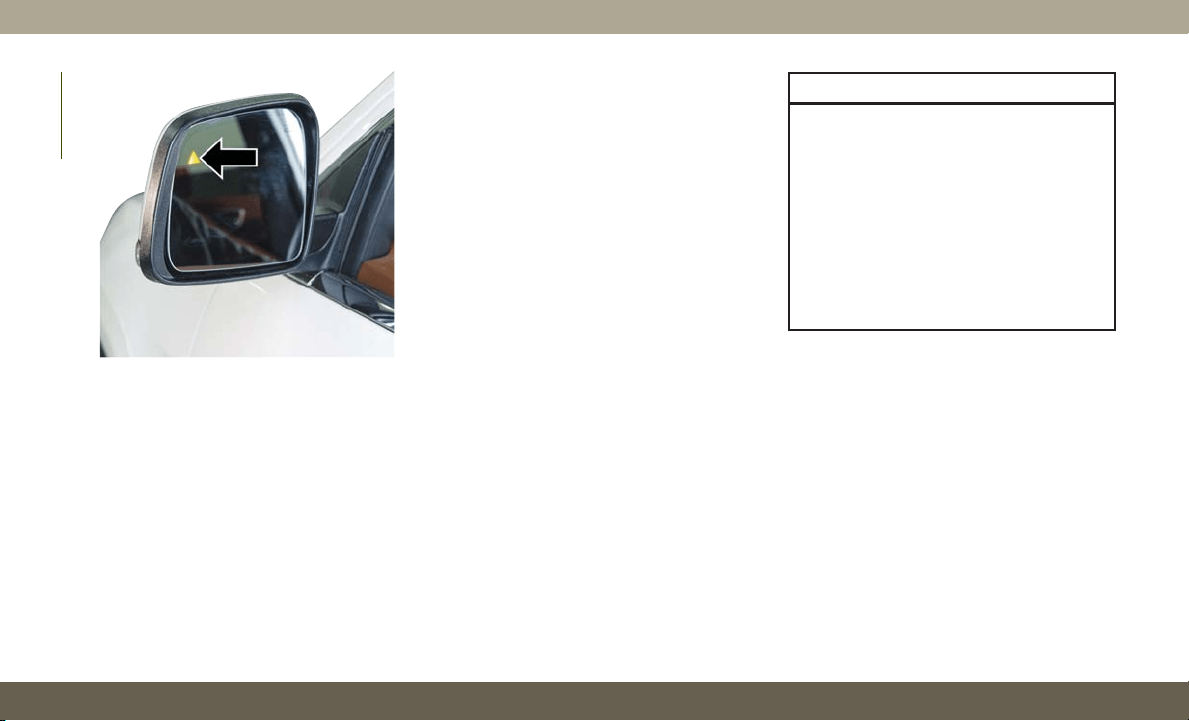
The BSM system monitors the detection zone
from three different entry points (side, rear,
front) while driving to see if an alert is nec-
essary. The BSM system will issue an alert
during these types of zone entries.
Entering From The Side
Vehicles that move into your adjacent lanes
from either side of the vehicle.
Entering From The Rear
Vehicles that come up from behind your ve-
hicle on either side and enter the rear detec-
tion zone with a relative speed of less than
30 mph (48 km/h).
Overtaking Traffic
If you pass another vehicle slowly with a
relative speed less than 15 mph (24 km/h)
and the vehicle remains in the blind spot for
approximately 1.5 seconds, the warning light
will be illuminated. If the difference in speed
between the two vehicles is greater than
15 mph (24 km/h), the warning light will not
illuminate.
The BSM system is designed not to issue an
alert on stationary objects such as guardrails,
posts, walls, foliage, berms, etc. However,
occasionally the system may alert on such
objects. This is normal operation and your
vehicle does not require service.
The BSM system will not alert you of objects
that are traveling in the opposite direction of
the vehicle in adjacent lanes.
WARNING!
The Blind Spot Monitoring system is only
an aid to help detect objects in the blind
spot zones. The BSM system is not de-
signed to detect pedestrians, bicyclists, or
animals. Even if your vehicle is equipped
with the BSM system, always check your
vehicle’s mirrors, glance over your shoul-
der, and use your turn signal before chang-
ing lanes. Failure to do so can result in
serious injury or death.
Rear Cross Path (RCP)
The Rear Cross Path (RCP) feature is in-
tended to aid the driver when backing out of
parking spaces where their vision of oncom-
ing vehicles may be blocked. Proceed slowly
and cautiously out of the parking space until
the rear end of the vehicle is exposed. The
RCP system will then have a clear view of the
cross traffic and if an oncoming vehicle is
detected, alert the driver.
Blind Spot Warning Light
SAFETY
100
RCP monitors the rear detection zones on
both sides of the vehicle, for objects that are
moving toward the side of the vehicle with a
minimum speed of approximately 5 mph
(8 km/h), to objects moving a maximum of
approximately 20 mph (32 km/h), such as in
parking lot situations.
NOTE:
In a parking lot situation, oncoming vehicles
can be obscured by vehicles parked on either
side. If the sensors are blocked by other
structures or vehicles, the system will not be
able to alert the driver.
When RCP is on and the vehicle is in RE-
VERSE, the driver is alerted using both the
visual and audible alarms, including reduc-
ing the radio volume.
WARNING!
Rear Cross Path Detection (RCP) is not a
back up aid system. It is intended to be
used to help a driver detect an oncoming
vehicle in a parking lot situation. Drivers
must be careful when backing up, even
WARNING!
when using RCP. Always check carefully
behind your vehicle, look behind you, and
be sure to check for pedestrians, animals,
other vehicles, obstructions, and blind
spots before backing up. Failure to do so
can result in serious injury or death.
Modes Of Operation
Three selectable modes of operation are
available in the Uconnect System. Refer to
“Uconnect Settings” in “Multimedia” in the
Owner’s Manual for further information.
Blind Spot Alert Lights Only
When operating in Blind Spot Alert mode, the
BSM system will provide a visual alert in the
appropriate side view mirror based on a de-
tected object. However, when the system is
operating in Rear Cross Path (RCP) mode, the
system will respond with both visual and
audible alerts when a detected object is pres-
ent. Whenever an audible alert is requested,
the radio is muted.
Blind Spot Alert Lights/Chime
When operating in Blind Spot Alert Lights/
Chime mode, the BSM system will provide a
visual alert in the appropriate side view mirror
based on a detected object. If the turn signal
is then activated, and it corresponds to an
alert present on that side of the vehicle, an
audible chime will also be sounded. When-
ever a turn signal and detected object are
present on the same side at the same time,
both the visual and audible alerts will be
issued. In addition to the audible alert the
radio (if on) will also be muted.
NOTE:
Whenever an audible alert is requested by the
BSM system, the radio is also muted.
When the system is in RCP, the system shall
respond with both visual and audible alerts
when a detected object is present. Whenever
an audible alert is requested, the radio is also
muted. Turn/hazard signal status is ignored;
the RCP state always requests the chime.
101

Blind Spot Alert Off
When the BSM system is turned off there will
be no visual or audible alerts from either the
BSM or RCP systems.
NOTE:
The BSM system will store the current oper-
ating mode when the vehicle is shut off. Each
time the vehicle is started the previously
stored mode will be recalled and used.
General Information
The following regulatory statement applies to
all Radio Frequency (RF) devices equipped in
this vehicle:
This device complies with Part 15 of the FCC
Rules and with Industry Canada license-
exempt RSS standard(s). Operation is sub-
ject to the following two conditions:
1. This device may not cause harmful inter-
ference.
2. This device must accept any interference
received, including interference that may
cause undesired operation.
NOTE:
Changes or modifications not expressly ap-
proved by the party responsible for compli-
ance could void the user’s authority to oper-
ate the equipment.
Forward Collision Warning (FCW) With
Mitigation
The Forward Collision Warning (FCW) with
Mitigation system provides the driver with
audible warnings, visual warnings (within the
instrument cluster display), and may apply a
brake jerk to warn the driver when it detects a
potential frontal collision. The warnings and
limited braking are intended to provide the
driver with enough time to react, avoid or
mitigate the potential collision.
NOTE:
FCW monitors the information from the for-
ward looking sensors as well as the Electronic
Brake Controller (EBC), to calculate the prob-
ability of a forward collision. When the sys-
tem determines that a forward collision is
probable, the driver will be provided with
audible and visual warnings and may provide
a brake jerk warning. If the driver does not
take action based upon these progressive
warnings, then the system will provide a lim-
ited level of active braking to help slow the
vehicle and mitigate the potential forward
collision. If the driver reacts to the warnings
by braking and the system determines that
the driver intends to avoid the collision by
braking but has not applied sufficient brake
force, the system will compensate and pro-
vide additional brake force as required.
If a Forward Collision Warning with Mitigation
event begins at a speed below 26 mph
(42 km/h), the system may provide the maxi-
mum or partial braking to mitigate the poten-
tial forward collision. If the Forward Collision
Warning with Mitigation event stops the ve-
hicle completely, the system will hold the
vehicle at a standstill for two seconds and
then release the brakes.
When the system determines a collision with
the vehicle in front of you is no longer probable,
the warning message will be deactivated.
SAFETY
102
NOTE:
• The minimum speed for FCW activation is
1 mph (2 km/h).
• The FCW alerts may be triggered on objects
other than vehicles such as guard rails or
sign posts based on the course prediction.
This is expected and is a part of normal
FCW activation and functionality.
• It is unsafe to test the FCW system. To
prevent such misuse of the system, after
four Active Braking events within an igni-
tion cycle, the Active Braking portion of
FCW will be deactivated until the next igni-
tion cycle.
• The FCW system is intended for on-road use
only. If the vehicle is taken off-road, the
FCW system should be deactivated to pre-
vent unnecessary warnings to the surround-
ings. If the vehicle enters 4WD Low Range
or ESC Full-Off Mode is active, the FCW
system will be automatically deactivated.
WARNING!
Forward Collision Warning (FCW) is not
intended to avoid a collision on its own,
WARNING!
nor can FCW detect every type of potential
collision. The driver has the responsibility
to avoid a collision by controlling the ve-
hicle via braking and steering. Failure to
follow this warning could lead to serious
injury or death.
FCW Braking Status And Sensitivity
The FCW Sensitivity and Active Braking sta-
tus are programmable through the Uconnect
System. Refer to “Uconnect Settings” in
“Multimedia” in the Owner’s Manual for fur-
ther information.
The default sensitivity of FCW is the “Me-
dium” setting and the system status is
“Warning & Braking”. This allows the system
to warn the driver of a possible collision with
the vehicle in front using audible/visual warn-
ings and it applies autonomous braking.
Changing the FCW status to “Far” setting
allows the system to warn the driver of a
possible collision with the vehicle in front
using audible/visual warning when the latter
is at a farther distance than "Medium" set-
ting. This provides the most reaction time to
avoid a possible collision.
Changing the FCW status to the “Near” set-
ting, allows the system to warn the driver of a
possible collision with the vehicle in front
when the distance between the vehicle in the
front is much closer. This setting provides
less reaction time than the “Far” and “Me-
dium” settings, which allows for a more dy-
namic driving experience.
NOTE:
• Changing the FCW status to “Only Warn-
ing” prevents the system from providing
limited active braking, or additional brake
support if the driver is not braking ad-
equately in the event of a potential frontal
collision, but maintains the audible and
visual warnings.
• Changing the FCW status to “Off” prevents
the system from providing autonomous
braking, or additional brake support if the
driver is not braking adequately in the event
of a potential frontal collision.
•
The system will retain the last setting se-
lected by the driver after ignition shut down.
103

• FCW may not react to irrelevant objects
such as overhead objects, ground reflec-
tions, objects not in the path of the vehicle,
stationary objects that are far away, oncom-
ing traffic, or leading vehicles with the
same or higher rate of speed.
• FCW will be disabled like ACC, with the
unavailable screens.
FCW Limited Warning
If the instrument cluster displays “ACC/FCW
Limited Functionality” or “ACC/FCW Limited
Functionality Clean Front Windshield” mo-
mentarily, there may be a condition that lim-
its FCW functionality. Although the vehicle is
still drivable under normal conditions, the
active braking may not be fully available.
Once the condition that limited the system
performance is no longer present, the system
will return to its full performance state. If the
problem persists, see your authorized dealer.
Service FCW Warning
If the system turns off, and the instrument
cluster displays:
• ACC/FCW Unavailable Service Required
• Cruise/FCW Unavailable Service Required
This indicates there is an internal system
fault. Although the vehicle is still drivable
under normal conditions, have the system
checked by an authorized dealer.
General Information
The following regulatory statement applies to
all Radio Frequency (RF) devices equipped in
this vehicle:
This device complies with Part 15 of the FCC
Rules and with Industry Canada license-
exempt RSS standard(s). Operation is sub-
ject to the following two conditions:
1. This device may not cause harmful inter-
ference.
2. This device must accept any interference
received, including interference that may
cause undesired operation.
NOTE:
Changes or modifications not expressly ap-
proved by the party responsible for compli-
ance could void the user’s authority to oper-
ate the equipment.
Tire Pressure Monitor System (TPMS)
NOTE:
For vehicles equipped with run flat tires —
when the TPMS indicates a tire pressure of
14 psi (96 kPa) or lower, always check tire
pressure and replace the tire at the first
opportunity. At inflation pressure of/or below
14 psi (96 kPa) the tire is in the run-flat
mode of operation. In this condition, it is
recommended a vehicle maximum speed of
50 mph (80 km/h) for a maximum distance of
50 miles (80 km). The manufacturer does
not recommend using the run flat feature
while driving a vehicle loaded at full capacity
or towing a trailer.
The Tire Pressure Monitoring System (TPMS)
will warn the driver of a low tire pressure
based on the vehicle recommended cold tire
pressure.
The tire pressure will vary with temperature
by about 1 psi (7 kPa) for every 12°F (6.5°C).
This means that when the outside tempera-
ture decreases, the tire pressure will de-
crease. Tire pressure should always be set
based on cold inflation tire pressure. This is
SAFETY
104

defined as the tire pressure after the vehicle
has not been driven for at least three hours, or
driven less than 1 mile (1.6 km) after a
three-hour period. Refer to “Tires” in “Servic-
ing And Maintenance” for information on how to
properly inflate the vehicle’s tires. The tire
pressure will also increase as the vehicle is
driven - this is normal and there should be no
adjustment for this increased pressure.
The TPMS will warn the driver of a low tire
pressure if the tire pressure falls below the
low pressure warning threshold for any rea-
son, including low temperature effects, or
natural pressure loss through the tire.
The TPMS will continue to warn the driver of
low tire pressure as long as the condition
exists, and will not turn off until the tire
pressure is at or above recommended cold
tire pressure. Once the low tire pressure
warning has been illuminated, the tire pres-
sure must be increased to the recommended
cold tire pressure in order for the TPMS
Warning Light to be turned off.
NOTE:
When filling warm tires, the tire pressure may
need to be increased up to an additional 4 psi
(28 kPa) above the recommended cold plac-
ard pressure in order to turn the TPMS Warn-
ing Light off.
The system will automatically update and the
TPMS Warning Light will extinguish once the
updated tire pressures have been received.
The vehicle may need to be driven for up to
20 minutes above 15 mph (24 km/h) to
receive this information.
For example, your vehicle has a recom-
mended cold (parked for more than three
hours) tire pressure of 33 psi (227 kPa). If
the ambient temperature is 68°F (20°C) and
the measured tire pressure is 28 psi
(193 kPa), a temperature drop to 20°F (-7°C)
will decrease the tire pressure to approxi-
mately 24 psi (165 kPa). This tire pressure is
sufficiently low enough to turn on the TPMS
Warning Light. Driving the vehicle may cause
the tire pressure to rise to approximately
28 psi (193 kPa), but the TPMS Warning
Light will still be on. In this situation, the
TPMS Warning Light will turn off only after
the tires have been inflated to the vehicle’s
recommended cold tire pressure value.
CAUTION!
•T
he TPMS has been optimized for the
original equipment tires and wheels.
TPMS pressures and warnings have been
established for the tire size equipped on
your vehicle. Undesirable system opera-
tion or sensor damage may result when
using replacement equipment that is not
of the same size, type, and/or style. The
TPM sensor is not designed for use on
aftermarket wheels and may contribute to
a poor overall system performance or sen-
sor damage. Customers are encouraged to
use OEM wheels to assure proper TPM
feature operation.
• Using aftermarket tire sealants may
cause the Tire Pressure Monitoring Sys-
tem (TPMS) sensor to become inoper-
able. After using an aftermarket tire
sealant it is recommended that you take
your vehicle to an authorized dealership
to have your sensor function checked.
105
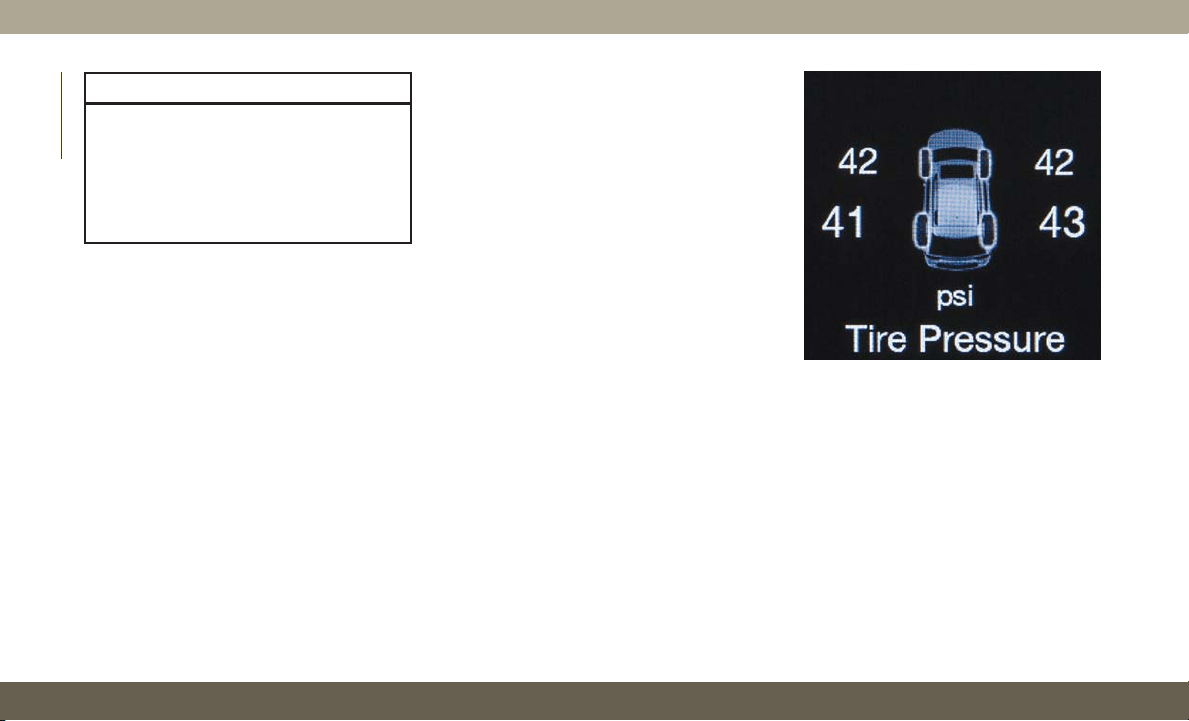
CAUTION!
• After inspecting or adjusting the tire
pressure, always reinstall the valve stem
cap. This will prevent moisture and dirt
from entering the valve stem, which
could damage the Tire Pressure Monitor-
ing Sensor.
NOTE:
• The TPMS is not intended to replace nor-
mal tire care and maintenance, or to pro-
vide warning of a tire failure or condition.
• The TPMS should not be used as a tire
pressure gauge while adjusting your tire
pressure.
• Driving on a significantly under-inflated tire
causes the tire to overheat and can lead to
tire failure. Under-inflation also reduces
fuel efficiency and tire tread life, and may
affect the vehicle’s handling and stopping
ability.
• The TPMS is not a substitute for proper tire
maintenance, and it is the driver’s respon-
sibility to maintain correct tire pressure
using an accurate tire gauge, even if under-
inflation has not reached the level to trigger
illumination of the TPMS Warning Light.
• Seasonal temperature changes will affect
tire pressure, and the TPMS will monitor
the actual tire pressure in the tire.
The Tire Pressure Monitor System (TPMS)
uses wireless technology with wheel rim-
mounted electronic sensors to monitor tire
pressure levels. Sensors, mounted to each
wheel as part of the valve stem, transmit tire
pressure readings to the Receiver Module.
NOTE:
It is particularly important, for you to regu-
larly check the tire pressure in all of your tires
and to maintain the proper pressure.
The Tire Pressure Monitor System (TPMS)
consists of the following components:
• Receiver Module
• Four Tire Pressure Monitoring Sensors
Tire Pressure Monitor Display
SAFETY
106
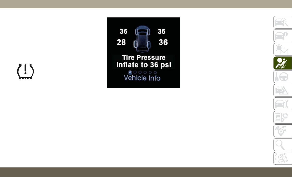
• Various Tire Pressure Monitoring System
Messages, which display in the instrument
cluster, and a graphic displaying tire pres-
sures
• TPMS Warning Light
Tire Pressure Monitoring Low Pressure
Warnings
The TPMS Warning Light will il-
luminate in the instrument clus-
ter, and an audible chime will be
activated, when one or more of
the four active road tire pres-
sures are low. In addition, the instrument
cluster will display an "Inflate to XX" message
and a graphic display of the pressure value(s)
with the low tire(s) in a different color. Refer
to “Instrument Cluster Display” in “Getting
To Know Your Instrument Panel” for further
information.
NOTE:
Your system can be set to display pressure
units in PSI, BAR or kPa.
Should a low tire condition occur on any of
the four active road tire(s), you should stop as
soon as possible, and inflate the low tire(s)
that is in a different color on the graphic
display to the vehicle’s recommended cold
tire pressure displayed in the “Inflate to XX”
message.
NOTE:
When filling warm tires, the tire pressure may
need to be increased up to an additional 4 psi
(28 kPa) above the recommended cold plac-
ard pressure in order to turn the TPMS Warn-
ing Light off.
The system will automatically update, the
graphic display of the pressure value(s) will
return to its original color and the TPMS
Warning Light will extinguish once the up-
dated tire pressure(s) have been received.
The vehicle may need to be driven for up to
20 minutes above 15 mph (24 km/h) to
receive this information.
Service TPM System Warning
The Tire Pressure Monitoring System Warning
Light will flash on and off for 75 seconds, and
remain on solid when a system fault is de-
tected. The system fault will also sound a
chime. The instrument cluster display will
display a “SERVICE TPM SYSTEM” message
for a minimum of five seconds. This message
is then followed by a graphic display, with
“- -“ in place of the pressure value(s), indi-
cating which Tire Pressure Monitoring Sen-
sor(s) is not being received.
Low Tire Pressure Monitor Display
107

If the ignition switch is cycled, this sequence
will repeat, providing the system fault still
exists. If the system fault no longer exists, the
Tire Pressure Monitoring System Warning
Light will no longer flash, the "SERVICE TPM
SYSTEM" message will not be present, and a
pressure value will be displayed instead of
dashes. A system fault can occur by any of
the following:
• Jamming due to electronic devices or driv-
ing next to facilities emitting the same
Radio Frequencies as the TPM sensors.
• Lots of snow or ice around the wheels or
wheel housings.
• Using tire chains on the vehicle.
• Using wheels/tires not equipped with TPM
sensors.
NOTE:
There is no tire pressure monitoring sensor in
the spare tire. The TPMS will not be able to
monitor the tire pressure. If you install the
spare tire in place of a road tire that has a
pressure below the low-pressure warning
limit, upon the next ignition switch cycle, the
Tire Pressure Monitoring System Warning
Light will remain on, a chime will sound, and
the instrument cluster display will still dis-
play a pressure value in the different color
graphic display and an “Inflate to XX” mes-
sage will be displayed. After driving the ve-
hicle for up to 20 minutes above 15 mph
(24 km/h), the Tire Pressure Monitoring Sys-
tem Warning Light will flash on and off for
75 seconds and then remain on solid. In
addition, the instrument cluster display will
display a “SERVICE TPM SYSTEM" message
for five seconds and then display dashes (- -)
in place of the pressure value. For each
subsequent ignition switch cycle, a chime
will sound, the Tire Pressure Monitoring Sys-
tem Warning Light will flash on and off for
75 seconds and then remain on solid, and
the instrument cluster display will display a
"SERVICE TPM SYSTEM" message for five
seconds and then display dashes (- -) in place
of the pressure value. Once you repair or
replace the original road tire, and reinstall it
on the vehicle in place of the spare tire, the
TPMS will update automatically.
In addition, the Tire Pressure Monitoring
System Warning Light will turn off and the
graphic in the instrument cluster display
will display a new pressure value instead of
dashes (- -), as long as no tire pressure is
below the low-pressure warning limit in any of
the four active road tires. The vehicle may
need to be driven for up to 20 minutes above
15 mph (24 km/h) in order for the TPMS to
receive this information.
TPMS Deactivation — If Equipped
The Tire Pressure Monitoring System (TPMS)
can be deactivated if replacing all four wheel
and tire assemblies (road tires) with wheel
and tire assemblies that do not have TPMS
Sensors, such as when installing winter
wheel and tire assemblies on your vehicle.
To deactivate the TPMS, first, replace all four
wheel and tire assemblies (road tires) with
tires not equipped with Tire Pressure Moni-
toring (TPM) Sensors. Then, drive the vehicle
for 20 minutes above 15 mph (24 km/h). The
TPMS will chime, the TPMS Warning Light
will flash on and off for 75 seconds and then
SAFETY
108

remain on. The instrument cluster will dis-
play the “SERVICE TPM SYSTEM” message
and then display dashes (--) in place of the
pressure values.
Beginning with the next ignition cycle, the
TPMS will no longer chime or display the
“SERVICE TPM SYSTEM” message in the
instrument cluster but dashes (--) will remain
in place of the pressure values.
To reactivate the TPMS, replace all four
wheel and tire assemblies (road tires) with
tires equipped with TPM sensors. Then, drive
the vehicle for up to 20 minutes above
15 mph (24 km/h). The TPMS will chime, the
TPMS Warning Light will flash on and off for
75 seconds and then turn off. The instrument
cluster will display the “SERVICE TPM SYS-
TEM” message and then display pressure
values in place of the dashes. On the next
ignition cycle the "SERVICE TPM SYSTEM"
message will no longer be displayed as long
as no system fault exists.
General Information
The following regulatory statement applies to
all radio frequency (RF) devices equipped in
this vehicle:
This device complies with Part 15 of the FCC
Rules and with Industry Canada license-
exempt RSS standard(s). Operation is sub-
ject to the following two conditions:
(1) This device may not cause harmful inter-
ference, and
(2) This device must accept any interference
received, including interference that may
cause undesired operation.
NOTE:
Changes or modifications not expressly ap-
proved by the party responsible for compli-
ance could void the user’s authority to oper-
ate the equipment.
OCCUPANT RESTRAINT
SYSTEMS
Some of the most important safety features in
your vehicle are the restraint systems:
Occupant Restraint Systems Features
• Seat Belt Systems
• Supplemental Restraint Systems (SRS) Air
Bags
• Supplemental Active Head Restraints
• Child Restraints
Some of the safety features described in this
section may be standard equipment on some
models, or may be optional equipment on
others. If you are not sure, ask an authorized
dealer.
Important Safety Precautions
Please pay close attention to the information
in this section. It tells you how to use your
restraint system properly, to keep you and
your passengers as safe as possible.
109

Here are some simple steps you can take to
minimize the risk of harm from a deploying
air bag:
1. Children 12 years old and under should
always ride buckled up in the rear seat of
a vehicle with a rear seat.
2. A child who is not big enough to wear the
vehicle seat belt properly (Refer to “Child
Restraints” in this section for further in-
formation) must be secured in the appro-
priate child restraint or belt-positioning
booster seat in a rear seating position.
3. If
a child from 2 to 12 years old (not in a
rear-facing child restraint) must ride in the
front passenger seat, move the seat as far
back as possible and use the proper child
restraint (Refer to “Child Restraints” in this
section for further information).
4. Never allow children to slide the shoulder
belt behind them or under their arm.
5. You should read the instructions provided
with your child restraint to make sure that
you are using it properly.
6. All occupants should always wear their lap
and shoulder belts properly.
7. The driver and front passenger seats
should be moved back as far as practical
to allow the front air bags room to inflate.
8. Do not lean against the door or window. If
your vehicle has side air bags, and deploy-
ment occurs, the side air bags will inflate
forcefully into the space between occu-
pants and the door and occupants could
be injured.
9. If the air bag system in this vehicle needs
to be modified to accommodate a dis-
abled person, refer to the “Customer As-
sistance” section for customer service
contact information.
WARNING!
• Never place a rear-facing child restraint
in front of an air bag. A deploying pas-
senger front air bag can cause death or
serious injury to a child 12 years or
younger, including a child in a rear-
facing child restraint.
WARNING!
• Never install a rear-facing child restraint
in the front seat of a vehicle. Only use a
rear-facing child restraint in the rear
seat. If the vehicle does not have a rear
seat, do not transport a rear-facing child
restraint in that vehicle.
Seat Belt Systems
Buckle up even though you are an excellent
driver, even on short trips. Someone on the
road may be a poor driver and could cause a
collision that includes you. This can happen
far away from home or on your own street.
Research has shown that seat belts save
lives, and they can reduce the seriousness of
injuries in a collision. Some of the worst
injuries happen when people are thrown from
the vehicle. Seat belts reduce the possibility
of ejection and the risk of injury caused by
striking the inside of the vehicle. Everyone in
a motor vehicle should be belted at all times.
SAFETY
110

Enhanced Seat Belt Use Reminder System
(BeltAlert)
Driver and Passenger BeltAlert (if equipped)
BeltAlert is a feature intended to remind
the driver and outboard front seat passenger
(if equipped with outboard front passenger
seat BeltAlert) to buckle their seat belts. The
Belt Alert feature is active whenever the igni-
tion switch is in the START or ON/RUN posi-
tion.
Initial Indication
If the driver is unbuckled when the ignition
switch is first in the START or ON/RUN posi-
tion, a chime will signal for a few seconds. If
the driver or outboard front seat passenger (if
equipped with outboard front passenger seat
BeltAlert) is unbuckled when the ignition
switch is first in the START or ON/RUN posi-
tion the Seat Belt Reminder Light will turn on
and remain on until both outboard front seat
belts are buckled. The outboard front passen-
ger seat BeltAlert is not active when an out-
board front passenger seat is unoccupied.
BeltAlert Warning Sequence
The BeltAlert warning sequence is activated
when the vehicle is moving above a specified
vehicle speed range and the driver or out-
board front seat passenger is unbuckled (if
equipped with outboard front passenger seat
BeltAlert) (the outboard front passenger seat
BeltAlert is not active when the outboard
front passenger seat is unoccupied). The
BeltAlert warning sequence starts by blinking
the Seat Belt Reminder Light and sounding
an intermittent chime. Once the BeltAlert
warning sequence has completed, the Seat
Belt Reminder Light will remain on until the
seat belts are buckled. The BeltAlert warning
sequence may repeat based on vehicle speed
until the driver and occupied outboard front
seat passenger seat belts are buckled. The
driver should instruct all occupants to buckle
their seat belts.
Change of Status
If the driver or outboard front seat passenger
(if equipped with outboard front passenger
seat BeltAlert) unbuckles their seat belt while
the vehicle is traveling, the BeltAlert warning
sequence will begin until the seat belts are
buckled again.
The outboard front passenger seat BeltAlert
is not active when the outboard front passen-
ger seat is unoccupied. BeltAlert may be
triggered when an animal or other items are
placed on the outboard front passenger seat
or when the seat is folded flat (if equipped). It
is recommended that pets be restrained in
the rear seat (if equipped) in pet harnesses or
pet carriers that are secured by seat belts,
and cargo is properly stowed.
BeltAlert can be activated or deactivated by
an authorized dealer. FCA US LLC does not
recommend deactivating BeltAlert.
NOTE:
If BeltAlert has been deactivated and the
driver or outboard front seat passenger (if
equipped with outboard front passenger seat
BeltAlert) is unbuckled the Seat Belt Re-
minder Light will turn on and remain on until
the driver and outboard front seat passenger
seat belts are buckled.
111
Lap/Shoulder Belts
All seating positions in your vehicle are
equipped with lap/shoulder belts.
The seat belt webbing retractor will lock only
during very sudden stops or collisions. This
feature allows the shoulder part of the seat
belt to move freely with you under normal
conditions. However, in a collision the seat
belt will lock and reduce your risk of striking
the inside of the vehicle or being thrown out
of the vehicle.
WARNING!
• Relying on the air bags alone could lead
to more severe injuries in a collision. The
air bags work with your seat belt to
restrain you properly. In some collisions,
the air bags won’t deploy at all. Always
wear your seat belt even though you have
air bags.
• In a collision, you and your passengers
can suffer much greater injuries if you
are not properly buckled up. You can
strike the interior of your vehicle or other
WARNING!
passengers, or you can be thrown out of
the vehicle. Always be sure you and
others in your vehicle ar
e buckled up
properly.
• It is dangerous to ride in a cargo area,
inside or outside of a vehicle. In a colli-
sion, people riding in these areas are
more likely to be seriously injured or
killed.
• Do not allow people to ride in any area of
your vehicle that is not equipped with
seats and seat belts.
• Be sure everyone in your vehicle is in a
seat and using a seat belt properly. Oc-
cupants, including the driver, should al-
ways wear their seat belts whether or not
an air bag is also provided at their seat-
ing position to minimize the risk of se-
vere injury or death in the event of a
crash.
• Wearing your seat belt incorrectly could
make your injuries in a collision much
worse. You might suffer internal injuries,
or you could even slide out of the seat
belt. Follow these instructions to wear
WARNING!
your seat belt safely and to keep your
passengers safe, too.
• Two people should never be belted into a
single seat belt. People belted together
can crash into one another in a collision,
hurting one another badly. Never use a
lap/shoulder belt or a lap belt for more
than one person, no matter what their
size.
WARNING!
• A lap belt worn too high can increase the
risk of injury in a collision. The seat belt
forces won’t be at the strong hip and
pelvic bones, but across your abdomen.
Always wear the lap part of your seat belt
as low as possible and keep it snug.
• A twisted seat belt may not protect you
properly. In a collision, it could even cut
into you. Be sure the seat belt is flat
against your body, without twists. If you
can’t straighten a seat belt in your ve-
hicle, take it to an authorized dealer
immediately and have it fixed.
SAFETY
112
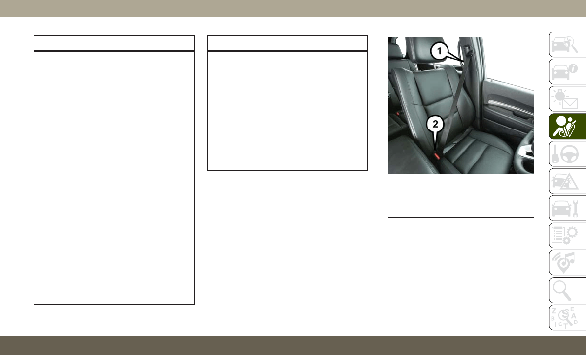
WARNING!
• A seat belt that is buckled into the wrong
buckle will not protect you properly. The
lap portion could ride too high on your
body, possibly causing internal injuries.
Always buckle your seat belt into the
buckle nearest you.
• A seat belt that is too loose will not
protect you properly. In a sudden stop,
you could move too far forward, increas-
ing the possibility of injury. Wear your
seat belt snugly.
• A seat belt that is worn under your arm is
dangerous. Your body could strike the
inside surfaces of the vehicle in a colli-
sion, increasing head and neck injury. A
seat belt worn under the arm can cause
internal injuries. Ribs aren’t as strong as
shoulder bones. Wear the seat belt over
your shoulder so that your strongest
bones will take the force in a collision.
• A shoulder belt placed behind you will
not protect you from injury during a
collision. You are more likely to hit your
head in a collision if you do not wear
WARNING!
your shoulder belt. The lap and shoulder
belt are meant to be used together.
• A frayed or torn seat belt could rip apart
in a collision and leave you with no
protection. Inspect the seat belt system
periodically, checking for cuts, frays, or
loose parts. Damaged parts must be re-
placed immediately. Do not disassemble
or modify the seat belt system. Seat belt
assemblies must be replaced after a
collision.
Lap/Shoulder Belt Operating Instructions
1. Enter the vehicle and close the door. Sit
back and adjust the seat.
2. The seat belt latch plate is above the back
of the front seat, and next to your arm in
the rear seat (for vehicles equipped with a
rear seat). Grasp the latch plate and pull
out the seat belt. Slide the latch plate up
the webbing as far as necessary to allow
the seat belt to go around your lap.
3. When the seat belt is long enough to fit,
insert the latch plate into the buckle until
you hear a “click.”
Pulling Out The Latch Plate
1 — Seat Belt
2 — Seat Belt Buckle
113
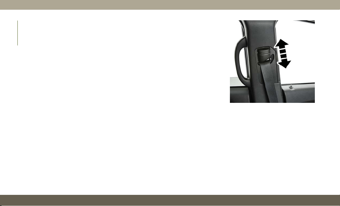
4. Position the lap belt so that it is snug and
lies low across your hips, below your ab-
domen. To remove slack in the lap belt
portion, pull up on the shoulder belt. To
loosen the lap belt if it is too tight, tilt the
latch plate and pull on the lap belt. A snug
seat belt reduces the risk of sliding under
the seat belt in a collision.
5. Position the shoulder belt across the
shoulder and chest with minimal, if any
slack so that it is comfortable and not
resting on your neck. The retractor will
withdraw any slack in the shoulder belt.
6. To release the seat belt, push the red
button on the buckle. The seat belt will
automatically retract to its stowed posi-
tion. If necessary, slide the latch plate
down the webbing to allow the seat belt to
retract fully.
Lap/Shoulder Belt Untwisting Procedure
Use the following procedure to untwist a
twisted lap/shoulder belt.
1. Position the latch plate as close as pos-
sible to the anchor point.
2. At about 6 to 12 inches (15 to 30 cm)
above the latch plate, grasp and twist the
seat belt webbing 180 degrees to create a
fold that begins immediately above the
latch plate.
3. Slide the latch plate upward over the
folded webbing. The folded webbing must
enter the slot at the top of the latch plate.
4. Continue to slide the latch plate up until it
clears the folded webbing and the seat
belt is no longer twisted.
Adjustable Upper Shoulder Belt Anchorage
In the driver and outboard front passenger
seats, the top of the shoulder belt can be
adjusted upward or downward to position
the seat belt away from your neck. Push or
squeeze the anchorage button to release the
anchorage, and move it up or down to the
position that serves you best.
As a guide, if you are shorter than average, you
will prefer the shoulder belt anchorage in a
lower position, and if you are taller than aver-
age, you will prefer the shoulder belt anchorage
in a higher position. After you release the
anchorage button, try to move it up or down to
make sure that it is locked in position.
NOTE:
The adjustable upper shoulder belt anchor-
age is equipped with an Easy Up feature.
Adjustable Anchorage
SAFETY
114
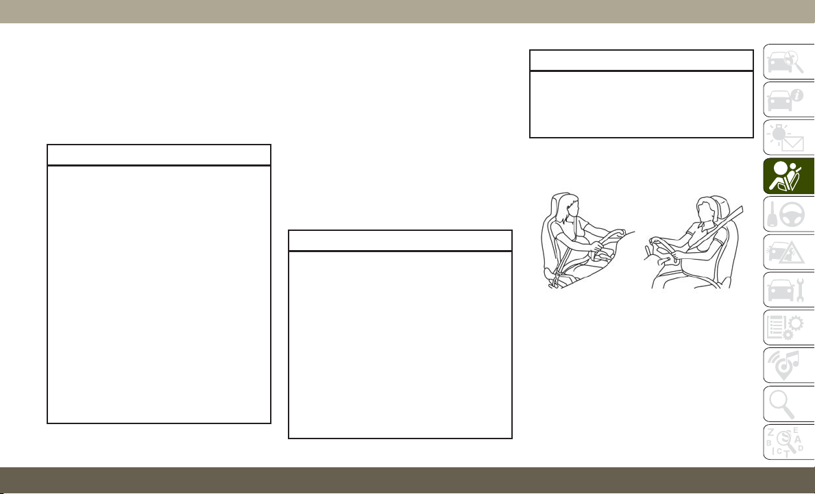
This feature allows the shoulder belt anchor-
age to be adjusted in the upward position
without pushing or squeezing the release but-
ton. To verify the shoulder belt anchorage is
latched, pull downward on the shoulder belt
anchorage until it is locked into position.
WARNING!
• Wearing your seat belt incorrectly could
make your injuries in a collision much
worse. You might suffer internal injuries,
or you could even slide out of the seat
belt. Follow these instructions to wear
your seat belt safely and to keep your
passengers safe, too.
• Position the shoulder belt across the
shoulder and chest with minimal, if any
slack so that it is comfortable and not
resting on your neck. The retractor will
withdraw any slack in the shoulder belt.
• Misadjustment of the seat belt could
reduce the effectiveness of the safety
belt in a crash.
• Always make all seat belt height adjust-
ments when the vehicle is stationary.
Seat Belt Extender
If a seat belt is not long enough to fit properly,
even when the webbing is fully extended and
the adjustable upper shoulder belt anchorage
(if equipped) is in its lowest position, an
authorized dealer can provide you with a Seat
Belt Extender. The Seat Belt Extender should
be used only if the existing seat belt is not
long enough. When the Seat Belt Extender is
not required for a different occupant, it must
be removed.
WARNING!
• ONLY use a Seat Belt Extender if it is
physically required in order to properly
fit the original seat belt system. DO NOT
USE the Seat Belt Extender if, when
worn, the distance between the front
edge of the Seat Belt Extender buckle
and the center of the occupant’s body is
LESS than 6 inches.
• Using a Seat Belt Extender when not
needed can increase the risk of serious
injury or death in a collision. Only use
the Seat Belt Extender when the lap belt
WARNING!
is not long enough and only use in the
recommended seating positions. Re-
move and store the Seat Belt Extender
when not needed.
Seat Belts And Pregnant Women
Seat belts must be worn by all occupants
including pregnant women: the risk of injury
in the event of an accident is reduced for the
mother and the unborn child if they are wear-
ing a seat belt.
Pregnant Women And Seat Belts
115
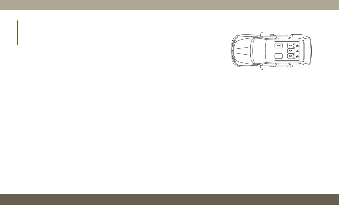
P
osition the lap belt snug and low below the
abdomen and across the strong bones of the
hips. Place the shoulder belt across the chest
and away from the neck. Never place the shoul-
der belt behind the back or under the arm.
Seat Belt Pretensioner
The front outboard seat belt system is
equipped with pretensioning devices that are
designed to remove slack from the seat belt
in the event of a collision. These devices may
improve the performance of the seat belt by
removing slack from the seat belt early in a
collision. Pretensioners work for all size oc-
cupants, including those in child restraints.
NOTE:
These devices are not a substitute for proper
seat belt placement by the occupant. The
seat belt still must be worn snugly and posi-
tioned properly.
The pretensioners are triggered by the Occu-
pant Restraint Controller (ORC). Like the air
bags, the pretensioners are single use items.
A deployed pretensioner or a deployed air bag
must be replaced immediately.
Energy Management Feature
The front outboard seat belt system is
equipped with an Energy Management fea-
ture that may help further reduce the risk of
injury in the event of a collision. The seat belt
system has a retractor assembly that is de-
signed to release webbing in a controlled
manner.
Switchable Automatic Locking Retractor
(ALR)
The seat belts in the passenger seating posi-
tions are equipped with a Switchable Auto-
matic Locking Retractor (ALR) which is used
to secure a child restraint system. For addi-
tional information, refer to “Installing Child
Restraints Using The Vehicle Seat Belt” un-
der the “Child Restraints” section of this
manual. The figure below illustrates the lock-
ing feature for each seating position.
If the passenger seating position is equipped
with an ALR and is being used for normal
usage, only pull the seat belt webbing out far
enough to comfortably wrap around the occu-
pant’s mid-section so as to not activate the
ALR. If the ALR is activated, you will hear a
clicking sound as the seat belt retracts. Allow
the webbing to retract completely in this case
and then carefully pull out only the amount of
webbing necessary to comfortably wrap
around the occupant’s mid-section. Slide the
latch plate into the buckle until you hear a
"click."
Automatic Locking Retractor (ALR)
Locations
SAFETY
116
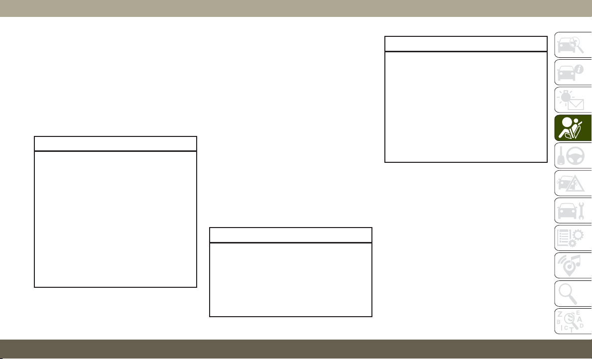
In Automatic Locking Mode, the shoulder
belt is automatically pre-locked. The seat
belt will still retract to remove any slack in the
shoulder belt. Use the Automatic Locking
Mode anytime a child restraint is installed in
a seating position that has a seat belt with
this feature. Children 12 years old and under
should always be properly restrained in the
rear seat of a vehicle with a rear seat.
WARNING!
• Never place a rear-facing child restraint
in front of an air bag. A deploying pas-
senger front air bag can cause death or
serious injury to a child 12 years or
younger, including a child in a rear-
facing child restraint.
• Never install a rear-facing child restraint
in the front seat of a vehicle. Only use a
rear-facing child restraint in the rear
seat. If the vehicle does not have a rear
seat, do not transport a rear-facing child
restraint in that vehicle.
How To Engage The Automatic Locking Mode
1. Buckle the combination lap and shoulder
belt.
2. Grasp the shoulder portion and pull down-
ward until the entire seat belt is extracted.
3. Allow the seat belt to retract. As the seat
belt retracts, you will hear a clicking
sound. This indicates the seat belt is now
in the Automatic Locking Mode.
How To Disengage The Automatic Locking Mode
Unbuckle the combination lap/shoulder belt
and allow it to retract completely to disen-
gage the Automatic Locking Mode and acti-
vate the vehicle sensitive (emergency) lock-
ing mode.
WARNING!
• The seat belt assembly must be replaced
if the switchable Automatic Locking Re-
tractor (ALR) feature or any other seat
belt function is not working properly
when checked according to the proce-
dures in the Service Manual.
WARNING!
• Failure to replace the seat belt assembly
could increase the risk of injury in colli-
sions.
• Do not use the Automatic Locking Mode
to restrain occupants who are wearing
the seat belt or children who are using
booster seats. The locked mode is only
used to install rear-facing or forward-
facing child restraints that have a har-
ness for restraining the child.
Supplemental Active Head Restraints (AHR)
These head restraints are passive, deployable
components, and vehicles with this equip-
ment cannot be readily identified by any
markings, only through visual inspection of
the head restraint. The head restraint will be
split in two halves, with the front half being
soft foam and trim, the back half being deco-
rative plastic.
117
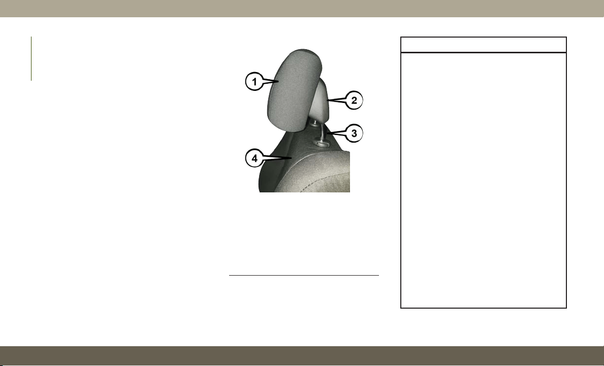
How The Active Head Restraints (AHR) Work
The Occupant Restraint Controller (ORC) de-
termines whether the severity or type of rear
impact will require the Active Head Re-
straints (AHR) to deploy. If a rear impact
requires deployment, both the driver and
front passenger seat AHRs will be deployed.
When AHRs deploy during a rear impact, the
front half of the head restraint extends for-
ward to minimize the gap between the back
of the occupant’s head and the AHR. This
system is designed to help prevent or reduce
the extent of injuries to the driver and front
passenger in certain types of rear impacts.
NOTE:
The Active Head Restraints (AHR) may or
may not deploy in the event of a front or side
impact. However, if during a front impact, a
secondary rear impact occurs, the AHR may
deploy based on the severity and type of the
impact.
Active Head Restraint (AHR) Components:
WARNING!
• All occupants, including the driver,
should not operate a vehicle or sit in a
vehicle’s seat until the head restraints
are placed in their proper positions in
order to minimize the risk of neck injury
in the event of a collision.
• Do not place items over the top of the
Active Head Restraint, such as coats,
seat covers or portable DVD players.
These items may interfere with the op-
eration of the Active Head Restraint in
the event of a collision and could result
in serious injury or death.
• Active Head Restraints may be deployed
if they are struck by an object such as a
hand, foot or loose cargo. To avoid acci-
dental deployment of the Active Head
Restraint, ensure that all cargo is se-
cured, as loose cargo could contact the
Active Head Restraint during sudden
stops. Failure to follow this warning
could cause personal injury if the Active
Head Restraint is deployed.
Active Head Restraint (AHR) Components
1 — Head Restraint Front Half (Soft
Foam And Trim)
2 — Head Restraint Back Half (Decora-
tive Plastic Rear Cover)
3 — Head Restraint Guide Tubes
4 — Seat Back
SAFETY
118
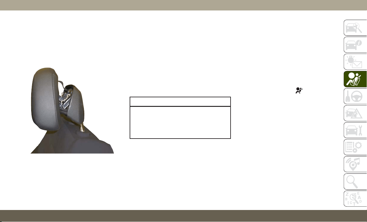
NOTE:
For more information on properly adjusting
and positioning the head restraint, refer to
“Head Restraints” in “Getting To Know Your
Vehicle.”
Resetting Active Head Restraints (AHR)
If the Active Head Restraints are triggered
during a collision, the front half of the head
restraint will be extended forward and sepa-
rated from the rear half of the head restraint
(See Image). Do not drive your vehicle after
the AHRs have deployed. The head restraint
must be reset into the original position to best
protect the occupant for all types of colli-
sions. An authorized FCA US LLC dealer must
reset the AHRs on the driver’s and front
passenger’s seat before driving. Personally
attempting to reset the AHRs may result in
damage to the AHRs that could impair their
function.
WARNING!
Deployed AHRs are not able to best protect
you in all types of collisions. Have de-
ployed AHRs reset by an authorized dealer
immediately.
Supplemental Restraint Systems (SRS )
Some of the safety features described in this
section may be standard equipment on some
models, or may be optional equipment on
others. If you are not sure, ask an authorized
dealer.
The air bag system must be ready to protect
you in a collision. The Occupant Restraint
Controller (ORC) monitors the internal cir-
cuits and interconnecting wiring associated
with the electrical Air Bag System Compo-
nents. Your vehicle may be equipped with the
following Air Bag System Components:
Air Bag System Components
• Occupant Restraint Controller (ORC)
• Air Bag Warning Light
• Steering Wheel and Column
• Instrument Panel
• Knee Impact Bolsters
• Driver and Front Passenger Air Bags
• Seat Belt Buckle Switch
• Supplemental Side Air Bags
• Supplemental Knee Air Bags
• Front and Side Impact Sensors
• Seat Belt Pretensioners
Active Head Restraint (AHR) Deployed
119

Air Bag Warning Light
The ORC monitors the readiness of the
electronic parts of the air bag system when-
ever the ignition switch is in the START or
ON/RUN position. If the ignition switch is in
the OFF position or in the ACC position, the
air bag system is not on and the air bags will
not inflate.
The ORC contains a backup power supply
system that may deploy the air bag system
even if the battery loses power or it becomes
disconnected prior to deployment.
The ORC turns on the Air Bag Warning Light
in the instrument panel for approximately
four to eight seconds for a self-check when
the ignition switch is first in the ON/RUN
position. After the self-check, the Air Bag
Warning Light will turn off. If the ORC detects
a malfunction in any part of the system, it
turns on the Air Bag Warning Light, either
momentarily or continuously. A single chime
will sound to alert you if the light comes on
again after initial startup.
T
he ORC also includes diagnostics that will
illuminate the instrument panel Air Bag Warn-
ing Light if a malfunction is detected that
could affect the air bag system. The diagnos-
tics also record the nature of the malfunction.
While the air bag system is designed to be
maintenance free, if any of the following oc-
curs, have an authorized dealer service the air
bag system immediately.
• The Air Bag Warning Light does not come
on during the four to eight seconds when
the ignition switch is first in the ON/RUN
position.
• The Air Bag Warning Light remains on after
the four to eight-second interval.
• The Air Bag Warning Light comes on inter-
mittently or remains on while driving.
NOTE:
If the speedometer, tachometer, or any en-
gine related gauges are not working, the Oc-
cupant Restraint Controller (ORC) may also
be disabled. In this condition the air bags
may not be ready to inflate for your protec-
tion. Have an authorized dealer service the
air bag system immediately.
WARNING!
Ignoring the Air Bag Warning Light in your
instrument panel could mean you won’t
have the air bag system to protect you in a
collision. If the light does not come on as
a bulb check when the ignition is first
turned on, stays on after you start the
vehicle, or if it comes on as you drive, have
an authorized dealer service the air bag
system immediately.
Redundant Air Bag Warning Light
If a fault with the Air Bag Warning Light is
detected, which could affect the Supplemen-
tal Restraint System (SRS), the Redundant
Air Bag Warning Light will illuminate on the
instrument panel. The Redundant Air Bag
Warning Light will stay on until the fault is
cleared. In addition, a single chime will
sound to alert you that the Redundant Air Bag
Warning Light has come on and a fault has
been detected. If the Redundant Air Bag
SAFETY
120
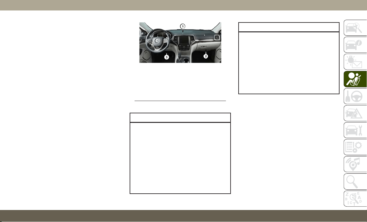
Warning Light comes on intermittently or
remains on while driving have an authorized
dealer service the vehicle immediately.
For additional information regarding the
Redundant Air Bag Warning Light refer to
“Getting To Know Your Instrument Panel”
section of this manual.
Front Air Bags
This vehicle has front air bags and lap/
shoulder belts for both the driver and front
passenger. The front air bags are a supple-
ment to the seat belt restraint systems. The
driver front air bag is mounted in the center of
the steering wheel. The passenger front air
bag is mounted in the instrument panel,
above the glove compartment. The words
“SRS AIRBAG” or “AIRBAG” are embossed
on the air bag covers.
WARNING!
• Being too close to the steering wheel or
instrument panel during front air bag
deployment could cause serious injury,
including death. Air bags need room to
inflate. Sit back, comfortably extending
your arms to reach the steering wheel or
instrument panel.
• Never place a rear-facing child restraint
in front of an air bag. A deploying pas-
senger front air bag can cause death or
WARNING!
serious injury to a child 12 years or
younger, including a child in a rear-
facing child restraint.
• Never install a rear-facing child restraint
in the front seat of a vehicle. Only use a
rear-facing child restraint in the rear
seat. If the vehicle does not have a rear
seat, do not transport a rear-facing child
restraint in that vehicle.
Driver And Passenger Front Air Bag Features
The Advanced Front Air Bag system has mul-
tistage driver and front passenger air bags.
This system provides output appropriate to
the severity and type of collision as deter-
mined by the Occupant Restraint Controller
(ORC), which may receive information from
the front impact sensors (if equipped) or
other system components.
The first stage inflator is triggered immedi-
ately during an impact that requires air bag
deployment. A low energy output is used in
less severe collisions. A higher energy output
is used for more severe collisions.
Front Air Bag/Knee Bolster Locations
1
— Driver And Passenger Front Air Bags
2 — Passenger Knee Impact Bolster
3 — Driver Knee Impact Bolster/
Supplemental Knee Air Bag
121
This vehicle may be equipped with a driver
and/or front passenger seat belt buckle
switch that detects whether the driver or front
passenger seat belt is buckled. The seat belt
buckle switch may adjust the inflation rate of
the Advanced Front Air Bags.
WARNING!
• No objects should be placed over or near
the air bag on the instrument panel or
steering wheel because any such objects
could cause harm if the vehicle is in a
collision severe enough to cause the air
bag to inflate.
• Do not put anything on or around the air
bag covers or attempt to open them
manually. You may damage the air bags
and you could be injured because the air
bags may no longer be functional. The
protective covers for the air bag cush-
ions are designed to open only when the
air bags are inflating.
• Relying on the air bags alone could lead
to more severe injuries in a collision. The
air bags work with your seat belt to
restrain you properly. In some collisions,
WARNING!
air bags won’t deploy at all. Always wear
your seat belts even though you have air
bags.
Front Air Bag Operation
Front Air Bags are designed to provide addi-
tional protection by supplementing the seat
belts. Front air bags are not expected to
reduce the risk of injury in rear, side, or
rollover collisions. The front air bags will not
deploy in all frontal collisions, including
some that may produce substantial vehicle
damage — for example, some pole collisions,
truck underrides, and angle offset collisions.
On the other hand, depending on the type and
location of impact, front air bags may deploy in
crashes with little vehicle front-end damage
but that produce a severe initial deceleration.
Because air bag sensors measure vehicle
deceleration over time, vehicle speed and
damage by themselves are not good indica-
tors of whether or not an air bag should have
deployed.
Seat belts are necessary for your protection in
all collisions, and also are needed to help
keep you in position, away from an inflating
air bag.
When the ORC detects a collision requiring
the front air bags, it signals the inflator units.
A large quantity of non-toxic gas is generated
to inflate the front air bags.
The steering wheel hub trim cover and the
upper passenger side of the instrument panel
separate and fold out of the way as the air
bags inflate to their full size. The front air
bags fully inflate in less time than it takes to
blink your eyes. The front air bags then
quickly deflate while helping to restrain the
driver and front passenger.
Knee Impact Bolsters
The Knee Impact Bolsters help protect the
knees of the driver and front passenger, and
position the front occupants for improved
interaction with the front air bags.
SAFETY
122

WARNING!
• Do not drill, cut, or tamper with the knee
impact bolsters in any way.
• Do not mount any accessories to the
knee impact bolsters such as alarm
lights, stereos, citizen band radios, etc.
Supplemental Driver Knee Air Bag
This vehicle is equipped with a Supplemental
Driver Knee Air Bag mounted in the instru-
ment panel below the steering column. The
Supplemental Driver Knee Air Bag provides
enhanced protection during a frontal impact
by working together with the seat belts, pre-
tensioners, and front air bags.
Supplemental Side Air Bags
Supplemental Seat-Mounted Side Air Bags
(SABs)
This vehicle is equipped with Supplemental
Seat-Mounted Side Air Bags (SABs).
Supplemental Seat-Mounted Side Air Bags
(SABs) are located in the outboard side of the
front seats. The SABs are marked with “SRS
AIRBAG” or “AIRBAG” on a label or on the
seat trim on the outboard side of the seats.
The SABs may help to reduce the risk of
occupant injury during certain side impacts,
in addition to the injury reduction potential
provided by the seat belts and body structure.
When the SAB deploys, it opens the seam on
the outboard side of the seatback’s trim
cover. The inflating SAB deploys through the
seat seam into the space between the occu-
pant and the door. The SAB moves at a very
high speed and with such a high force that it
could injure occupants if they are not seated
properly, or if items are positioned in the area
where the SAB inflates. Children are at an
even greater risk of injury from a deploying
air bag.
WARNING!
Do not use accessory seat covers or place
objects between you and the Side Air
Bags; the performance could be adversely
affected and/or objects could be pushed
into you, causing serious injury.
Front Supplemental Seat-Mounted Side
Air Bag Label
123
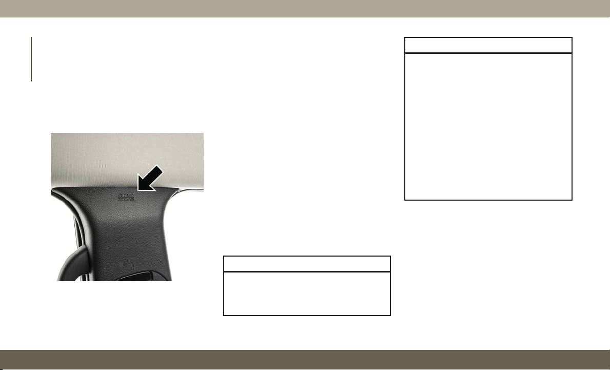
Supplemental Side Air Bag Inflatable Curtains
(SABICs)
This vehicle is equipped with Supplemental
Side Air Bag Inflatable Curtains (SABICs).
Supplemental Side Air Bag Inflatable Cur-
tains (SABICs) are located above the side
windows. The trim covering the SABICs is
labeled “SRS AIRBAG” or “AIRBAG.”
SABICs may help reduce the risk of head and
other injuries to front and rear seat outboard
occupants in certain side impacts, in addi-
tion to the injury reduction potential provided
by the seat belts and body structure.
The SABIC deploys downward, covering the
side windows. An inflating SABIC pushes the
outside edge of the headliner out of the way
and covers the window. The SABICs inflate
with enough force to injure occupants if they
are not belted and seated properly, or if items
are positioned in the area where the SABICs
inflate. Children are at an even greater risk of
injury from a deploying air bag.
The SABICs may help reduce the risk of
partial or complete ejection of vehicle occu-
pants through side windows in certain side
impact events.
WARNING!
• Do not mount equipment, or stack lug-
gage or other cargo up high enough
to block the deployment of the SABICs.
WARNING!
The trim covering above the side win-
dows where the SABIC and its deploy-
ment path are located should remain
free from any obstructions.
• In order for the SABICs to work as in-
tended, do not install any accessory
items in your vehicle which could alter
the roof. Do not add an aftermarket
sunroof to your vehicle. Do not add roof
racks that require permanent attach-
ments (bolts or screws) for installation
on the vehicle roof. Do not drill into the
roof of the vehicle for any reason.
Side Impacts
The Side Air Bags are designed to activate in
certain side impacts. The Occupant Restraint
Controller (ORC) determines whether the de-
ployment of the Side Air Bags in a particular
impact event is appropriate, based on the
severity and type of collision. The side impact
sensors aid the ORC in determining the ap-
propriate response to impact events. The
system is calibrated to deploy the Side Air
Supplemental Side Air Bag Inflatable
Curtain (SABIC) Label Location
SAFETY
124
Bags on the impact side of the vehicle during
impacts that require Side Air Bag occupant
protection. In side impacts, the Side Air Bags
deploy independently; a left side impact de-
ploys the left Side Air Bags only and a right-
side impact deploys the right Side Air Bags
only. Vehicle damage by itself is not a good
indicator of whether or not Side Air Bags
should have deployed.
The Side Air Bags will not deploy in all side
collisions, including some collisions at cer-
tain angles, or some side collisions that do
not impact the area of the passenger com-
partment. The Side Air Bags may deploy
during angled or offset frontal collisions
where the front air bags deploy.
Side Air Bags are a supplement to the seat
belt restraint system. Side Air Bags deploy in
less time than it takes to blink your eyes.
WARNING!
• Occupants, including children, who are
up against or very close to Side Air Bags
can be seriously injured or killed. Occu-
pants, including children, should never
WARNING!
lean on or sleep against the door, side
windows, or area where the side air bags
inflate, even if they are in an infant or
child restraint.
• Seat belts (and child restraints where
appropriate) are necessary for your pro-
tection in all collisions. They also help
keep you in position, away from an in-
flating Side Air Bag. To get the best
protection from the Side Air Bags, occu-
pants must wear their seat belts properly
and sit upright with their backs against
the seats. Children must be properly
restrained in a child restraint or booster
seat that is appropriate for the size of the
child.
WARNING!
• Side Air Bags need room to inflate. Do
not lean against the door or window. Sit
upright in the center of the seat.
• Being too close to the Side Air Bags
during deployment could cause you to
be severely injured or killed.
WARNING!
• Relying on the Side Air Bags alone could
lead to more severe injuries in a colli-
sion. The Side Air Bags work with your
seat belt to restrain you properly. In
some collisions, Side Air Bags won’t
deploy at all. Always wear your seat belt
even though you have Side Air Bags.
NOTE:
Air bag covers may not be obvious in the
interior trim, but they will open during air bag
deployment.
Rollover Events
Side Air Bags are designed to activate in
certain rollover events. The ORC determines
whether the deployment of the Side Air Bags
in a particular rollover event is appropriate,
based on the severity and type of collision.
Vehicle damage by itself is not a good indica-
tor of whether or not Side Air Bags should
have deployed.
125

The Side Air Bags will not deploy in all rollover
events. The rollover sensing system determines
if a rollover event may be in progress and
whether deployment is appropriate. In the
event the vehicle experiences a rollover or near
rollover event, and deployment of the Side Air
Bags is appropriate, the rollover sensing sys-
tem will also deploy the seat belt pretensioners
on both sides of the vehicle.
The SABICs may help reduce the risk of
partial or complete ejection of vehicle occu-
pants through side windows in certain roll-
over or side impact events.
Air Bag System Components
NOTE:
The Occupant Restraint Controller (ORC)
monitors the internal circuits and intercon-
necting wiring associated with electrical Air
Bag System Components listed below:
• Occupant Restraint Controller (ORC)
• Air Bag Warning Light
• Steering Wheel and Column
• Instrument Panel
• Knee Impact Bolsters
• Driver and Front Passenger Air Bags
• Seat Belt Buckle Switch
• Supplemental Side Air Bags
• Supplemental Knee Air Bags
• Front and Side Impact Sensors
• Seat Belt Pretensioners
If A Deployment Occurs
The front air bags are designed to deflate
immediately after deployment.
NOTE:
Front and/or side air bags will not deploy in
all collisions. This does not mean something
is wrong with the air bag system.
If you do have a collision which deploys the
air bags, any or all of the following may occur:
• The air bag material may sometimes cause
abrasions and/or skin reddening to the oc-
cupants as the air bags deploy and unfold.
The abrasions are similar to friction rope
burns or those you might get sliding along a
carpet or gymnasium floor. They are not
caused by contact with chemicals. They are
not permanent and normally heal quickly.
However, if you haven’t healed significantly
within a few days, or if you have any blis-
tering, see your doctor immediately.
• As the air bags deflate, you may see some
smoke-like particles. The particles are a
normal by-product of the process that gen-
erates the non-toxic gas used for air bag
inflation. These airborne particles may irri-
tate the skin, eyes, nose, or throat. If you
have skin or eye irritation, rinse the area
with cool water. For nose or throat irritation,
move to fresh air. If the irritation continues,
see your doctor. If these particles settle on
your clothing, follow the garment manufac-
turer’s instructions for cleaning.
Do not drive your vehicle after the air bags
have deployed. If you are involved in another
collision, the air bags will not be in place to
protect you.
WARNING!
Deployed air bags and seat belt preten-
sioners cannot protect you in another
collision. Have the air bags, seat belt pre-
tensioners, and the seat belt retractor
SAFETY
126
WARNING!
assemblies replaced by an authorized
dealer immediately. Also, have the Occu-
pant Restraint Controller System serviced
as well.
NOTE:
• Air bag covers may not be obvious in the
interior trim, but they will open during air
bag deployment.
• After any collision, the vehicle should be
taken to an authorized dealer immediately.
Enhanced Accident Response System
In the event of an impact, if the communica-
tion network remains intact, and the power
remains intact, depending on the nature of
the event, the ORC will determine whether to
have the Enhanced Accident Response Sys-
tem perform the following functions:
• Cut off fuel to the engine (If Equipped)
• Cut off battery power to the electric motor
(If Equipped)
• Flash hazard lights as long as the battery
has power
• Turn on the interior lights, which remain on
as long as the battery has power or for 15
minutes from the intervention of the En-
hanced Accident Response System.
• Unlock the power door locks.
Your vehicle may also be designed to perform
any of these other functions in response to
the Enhanced Accident Response System:
• Turn off the Fuel Filter Heater, Turn off the
HVAC Blower Motor, Close the HVAC Circu-
lation Door
• Cut off battery power to the:
– Engine
– Electric Motor (if equipped)
– Electric power steering
– Brake booster
– Electric park brake
– Automatic transmission gear selector
– Horn
– Front wiper
– Headlamp washer pump
NOTE:
After an accident, remember to cycle the
ignition to the STOP (OFF/LOCK) position
and remove the key from the ignition switch
to avoid draining the battery. Carefully check
the vehicle for fuel leaks in the engine com-
partment and on the ground near the engine
compartment and fuel tank before resetting
the system and starting the engine. If there
are no fuel leaks or damage to the vehicle
electrical devices (e.g. headlights) after an
accident, reset the system by following the
procedure described below. If you have any
doubt, contact an authorized dealer.
Enhanced Accident Response System Reset
Procedure
In order to reset the Enhanced Accident Re-
sponse System functions after an event, the
ignition switch must be changed from igni-
tion START or ON/RUN to ignition OFF. Care-
fully check the vehicle for fuel leaks in the
engine compartment and on the ground near
the engine compartment and fuel tank before
resetting the system and starting the engine.
127

Maintaining Your Air Bag System
WARNING!
•
Modifications to any part of the air bag
system could cause it to fail when you
need it. You could be injured if the air bag
system is not there to protect you. Do not
modify the components or wiring, includ-
ing adding any kind of badges or stickers
to the steering wheel hub trim cover or the
upper passenger side of the instrument
panel. Do not modify the front bumper,
vehicle body structure, or add aftermarket
side steps or running boards.
• It is dangerous to try to repair any part of
the air bag system yourself. Be sure to
tell anyone who works on your vehicle
that it has an air bag system.
• Do not attempt to modify any part of your
air bag system. The air bag may inflate
accidentally or may not function prop-
erly if modifications are made. Take your
vehicle to an authorized dealer for any
air bag system service. If your seat, in-
cluding your trim cover and cushion,
needs to be serviced in any way (includ-
WARNING!
ing removal or loosening/tightening of
seat attachment bolts), take the vehicle
to an authorized dealer. Only manufac-
turer approved seat accessories may be
used. If it is necessary to modify the air
bag system for persons with disabilities,
contact an authorized dealer.
Event Data Recorder (EDR)
This vehicle is equipped with an event data
recorder (EDR). The main purpose of an EDR
is to record, in certain crash or near crash-
like situations, such as an air bag deployment
or hitting a road obstacle, data that will assist
in understanding how a vehicle’s systems
performed. The EDR is designed to record
data related to vehicle dynamics and safety
systems for a short period of time, typically
30 seconds or less. The EDR in this vehicle is
designed to record such data as:
• How various systems in your vehicle were
operating;
• Whether or not the driver and passenger
safety belts were buckled/fastened;
• How far (if at all) the driver was depressing
the accelerator and/or brake pedal; and,
• How fast the vehicle was traveling.
These data can help provide a better under-
standing of the circumstances in which
crashes and injuries occur.
NOTE:
EDR data are recorded by your vehicle only if
a non-trivial crash situation occurs; no data
are recorded by the EDR under normal driving
conditions and no personal data (e.g., name,
gender, age, and crash location) are re-
corded. However, other parties, such as law
enforcement, could combine the EDR data
with the type of personally identifying data
routinely acquired during a crash investiga-
tion.
To read data recorded by an EDR, special
equipment is required, and access to the
vehicle or the EDR is needed. In addition to
the vehicle manufacturer, other parties, such
as law enforcement, that have the special
equipment, can read the information if they
have access to the vehicle or the EDR.
SAFETY
128
Child Restraints
E
veryone in your vehicle needs to be buckled
up at all times, including babies and children.
Every state in the United States, and every
Canadian province, requires that small chil-
dren ride in proper restraint systems. This is
the law, and you can be prosecuted for ignoring
it.
Children 12 years or younger should ride
properly buckled up in a rear seat, if avail-
able. According to crash statistics, children
are safer when properly restrained in the rear
seats rather than in the front.
WARNING!
In a collision, an unrestrained child can
become a projectile inside the vehicle. The
force required to hold even an infant on
your lap could become so great that you
could not hold the child, no matter how
strong you are. The child and others could
be badly injured or killed. Any child riding
in your vehicle should be in a proper re-
straint for the child’s size.
There are different sizes and types of re-
straints for children from newborn size to the
child almost large enough for an adult safety
belt. Always check the child seat Owner’s
Manual to make sure you have the correct
seat for your child. Carefully read and follow
all the instructions and warnings in the child
restraint Owner’s Manual and on all the labels
attached to the child restraint.
Before buying any restraint system, make
sure that it has a label certifying that it meets
all applicable Safety Standards. You should
also make sure that you can install it in the
vehicle where you will use it.
NOTE:
• For additional information, refer to http://
www.nhtsa.gov/parents-and-caregivers or
call: 1–888–327–4236
•
Canadian residents should refer to Transport
Canada’s website for additional information:
http://www.tc.gc.ca/eng/motorvehiclesafety/
safedrivers-childsafety-index-53.htm
Summary Of Recommendations For Restraining Children In Vehicles
Child Size, Height, Weight Or Age Recommended Type Of Child Restraint
Infants and Toddlers
Children who are two years old or younger and who
have not reached the height or weight limits of their
child restraint
Either an Infant Carrier or a Convertible Child Re-
straint, facing rearward in a rear seat of the vehicle
Small Children
Children who are at least two years old or who have
outgrown the height or weight limit of their rear-facing
child restraint
Forward-Facing Child Restraint with a five-point Har-
ness, facing forward in a rear seat of the vehicle
129
Child Size, Height, Weight Or Age Recommended Type Of Child Restraint
Larger Children
Children who have outgrown their forward-facing child
restraint, but are too small to properly fit the vehicle’s
seat belt
Belt Positioning Booster Seat and the vehicle seat
belt, seated in a rear seat of the vehicle
Children Too Large for Child
Restraints
Children 12 years old or younger, who have outgrown
the height or weight limit of their booster seat
Vehicle Seat Belt, seated in a rear seat of the vehicle
Infant And Child Restraints
Safety experts recommend that children ride
rear-facing in the vehicle until they are two
years old or until they reach either the height
or weight limit of their rear-facing child re-
straint. Two types of child restraints can be
used rear-facing: infant carriers and convert-
ible child seats.
The infant carrier is only used rear-facing in
the vehicle. It is recommended for children
from birth until they reach the weight or
height limit of the infant carrier. Convertible
child seats can be used either rear-facing or
forward-facing in the vehicle. Convertible
child seats often have a higher weight limit in
the rear-facing direction than infant carriers
do, so they can be used rear-facing by chil-
dren who have outgrown their infant carrier
but are still less than at least two years old.
Children should remain rear-facing until they
reach the highest weight or height allowed by
their convertible child seat.
WARNING!
• Never place a rear-facing child restraint
in front of an air bag. A deploying pas-
senger front air bag can cause death or
serious injury to a child 12 years or
younger, including a child in a rear-
facing child restraint.
• Never install a rear-facing child restraint
in the front seat of a vehicle. Only use a
rear-facing child restraint in the rear
seat. If the vehicle does not have a rear
seat, do not transport a rear-facing child
restraint in that vehicle.
Older Children And Child Restraints
Children who are two years old or who have
outgrown their rear-facing convertible child
seat can ride forward-facing in the vehicle.
Forward-facing child seats and convertible
child seats used in the forward-facing direction
are for children who are over two years old or
who have outgrown the rear-facing weight or
height limit of their rear-facing convertible
child seat. Children should remain in a
forward-facing child seat with a harness for as
long as possible, up to the highest weight or
height allowed by the child seat.
All children whose weight or height is above
the forward-facing limit for the child seat
should use a belt-positioning booster seat
until the vehicle’s seat belts fit properly. If
the child cannot sit with knees bent over the
vehicle’s seat cushion while the child’s back
SAFETY
130
is against the seatback, they should use a
belt-positioning booster seat. The child and
belt-positioning booster seat are held in the
vehicle by the seat belt.
WARNING!
• Improper installation can lead to failure
of an infant or child restraint. It could
come loose in a collision. The child
could be badly injured or killed. Follow
the child restraint manufacturer’s direc-
tions exactly when installing an infant or
child restraint.
• After a child restraint is installed in the
vehicle, do not move the vehicle seat
forward or rearward because it can
loosen the child restraint attachments.
Remove the child restraint before ad-
justing the vehicle seat position. When
the vehicle seat has been adjusted, re-
install the child restraint.
• When your child restraint is not in use,
secure it in the vehicle with the seat belt
or LATCH anchorages, or remove it from
the vehicle. Do not leave it loose in the
vehicle. In a sudden stop or accident, it
WARNING!
could strike the occupants or seatbacks
and cause serious personal injury.
Children Too Large For Booster Seats
Children who are large enough to wear the
shoulder belt comfortably, and whose legs are
long enough to bend over the front of the seat
when their back is against the seatback,
should use the seat belt in a rear seat. Use
this simple 5-step test to decide whether the
child can use the vehicle’s seat belt alone:
1. Can the child sit all the way back against
the back of the vehicle seat?
2. Do the child’s knees bend comfortably
over the front of the vehicle seat – while
the child is still sitting all the way back?
3. Does the shoulder belt cross the child’s
shoulder between the neck and arm?
4. Is the lap part of the belt as low as
possible, touching the child’s thighs and
not the stomach?
5. Can the child stay seated like this for the
whole trip?
If the answer to any of these questions was
“no,” then the child still needs to use a
booster seat in this vehicle. If the child is
using the lap/shoulder belt, check seat belt
fit periodically and make sure the seat belt
buckle is latched. A child’s squirming or
slouching can move the belt out of position. If
the shoulder belt contacts the face or neck,
move the child closer to the center of the
vehicle, or use a booster seat to position the
seat belt on the child correctly.
WARNING!
Never allow a child to put the shoulder belt
under an arm or behind their back. In a
crash, the shoulder belt will not protect a
child properly, which may result in serious
injury or death. A child must always wear
both the lap and shoulder portions of the
seat belt correctly.
131

Recommendations For Attaching Child Restraints
Restraint Type Combined Weight of the
Child + Child Restraint
Use Any Attachment Method Shown With An “X” Below
LATCH – Lower Anchors
Only
Seat Belt Only LATCH – Lower Anchors
+ Top Tether Anchor
Seat Belt + Top Tether
Anchor
Rear-Facing Child
Restraint
Up to 65 lbs (29.5 kg)
XX
Rear-Facing Child
Restraint
More than 65 lbs
(29.5 kg)
X
Forward-Facing Child
Restraint
Up to 65 lbs (29.5 kg) X X
Forward-Facing Child
Restraint
More than 65 lbs
(29.5 kg)
X
SAFETY
132
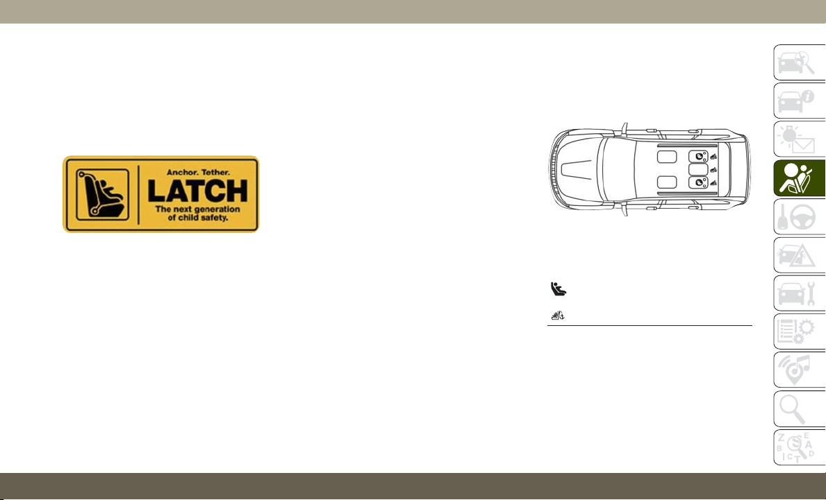
Lower Anchors And Tethers For CHildren
(LATCH) Restraint System
Your vehicle is equipped with the child re-
straint anchorage system called LATCH,
which stands for Lower Anchors and Tethers
for CHildren. The LATCH system has three
vehicle anchor points for installing LATCH-
equipped child seats. There are two lower
anchorages located at the back of the seat
cushion where it meets the seatback and one
top tether anchorage located behind the seat-
ing position. These anchorages are used to
install LATCH-equipped child seats without
using the vehicle’s seat belts. Some seating
positions may have a top tether anchorage
but no lower anchorages. In these seating
positions, the seat belt must be used with the
top tether anchorage to install the child re-
straint. Please see the following table for
more information.
LATCH Positions For Installing Child
Restraints In This Vehicle
LATCH Label
LATCH Positions For Installing Child
Restraints In This Vehicle
Lower Anchorage Symbol
(2 Anchorages Per Seating Position)
Top Tether Anchorage Symbol
133

Frequently Asked Questions About Installing Child Restraints With LATCH
What is the weight limit (child’s weight + weight of
the child restraint) for using the LATCH anchorage
system to attach the child restraint?
65 lbs (29.5 kg)
Use the LATCH anchorage system until the combined weight of
the child and the child restraint is 65 lbs (29.5 kg). Use the
seat belt and tether anchor instead of the LATCH system once
the combined weight is more than 65 lbs (29.5 kg).
Can the LATCH anchorages and the seat belt be
used together to attach a rear-facing or forward-
facing child restraint?
No
Do not use the seat belt when you use the LATCH anchorage
system to attach a rear-facing or forward-facing child restraint.
Booster seats may be attached to the LATCH anchorages if
allowed by the booster seat manufacturer. See your booster seat
owner’s manual for more information.
Can a child seat be installed in the center position
using the inner LATCH lower anchorages?
No
Use the seat belt and tether anchor to install a child seat in the
center seating position.
Can two child restraints be attached using a com-
mon lower LATCH anchorage?
No
Never “share” a LATCH anchorage with two or more child re-
straints. If the center position does not have dedicated LATCH
lower anchorages, use the seat belt to install a child seat in the
center position next to a child seat using the LATCH anchorages
in an outboard position.
Can the rear-facing child restraint touch the back of
the front passenger seat?
Yes
The child seat may touch the back of the front passenger seat if
the child restraint manufacturer also allows contact. See your
child restraint owner’s manual for more information.
Can the rear head restraints be removed? Yes
The head restraint may be removed in only the center seating
position if it interferes with the installation of the child
restraint.
Refer to “Head Restraints” in Getting To Know Your Vehicle
for further information.
SAFETY
134
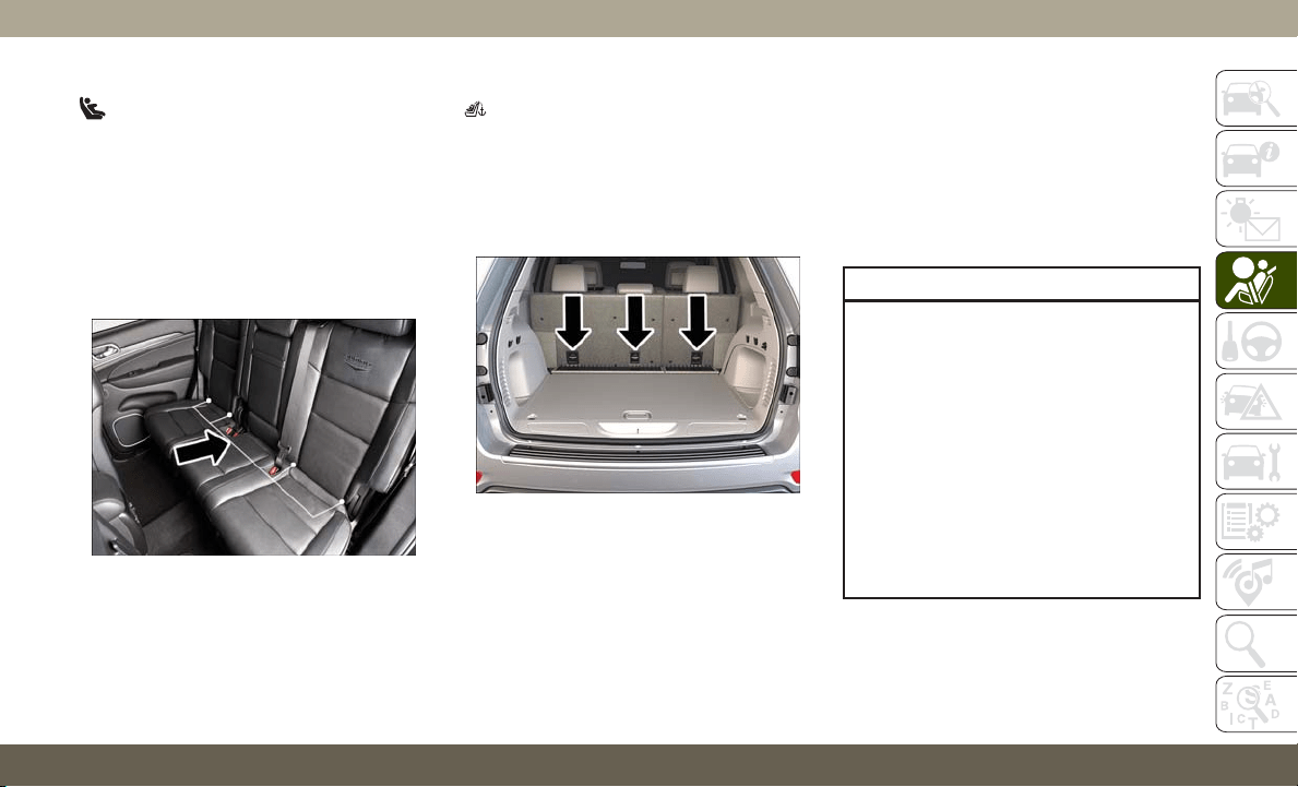
Locating The LATCH Anchorages
The lower anchorages are round bars that are
found at the rear of the seat cushion where it
meets the seatback, below the anchorage
symbols on the seatback. They are just visible
when you lean into the rear seat to install the
child restraint. You will easily feel them if you
run your finger along the gap between the
seatback and seat cushion.
Locating The Upper Tether Anchorages
There are tether strap anchorages behind each
rear seating position located on the back of the
seat. To access them, pull the carpeted floor
panel away from the seat back, this will expose
the top tether strap anchorages.
LATCH-compatible child restraint systems
will be equipped with a rigid bar or a flexible
strap on each side. Each will have a hook or
connector to attach to the lower anchorage
and a way to tighten the connection to the
anchorage. Forward-facing child restraints
and some rear-facing child restraints will also
be equipped with a tether strap. The tether
strap will have a hook at the end to attach to
the top tether anchorage and a way to tighten
the strap after it is attached to the anchorage.
Center Seat LATCH
WARNING!
• Do not install a child restraint in the
center position using the LATCH system.
This position is not approved for install-
ing child seats using the LATCH attach-
ments. You must use the seat belt and
tether anchor to install a child seat in the
center seating position.
• Never use the same lower anchorage to
attach more than one child restraint.
Please refer to “To Install A LATCH-
Compatible Child Restraint” for typical
installation instructions.
LATCH Anchorages
Tether Strap Anchorages
135
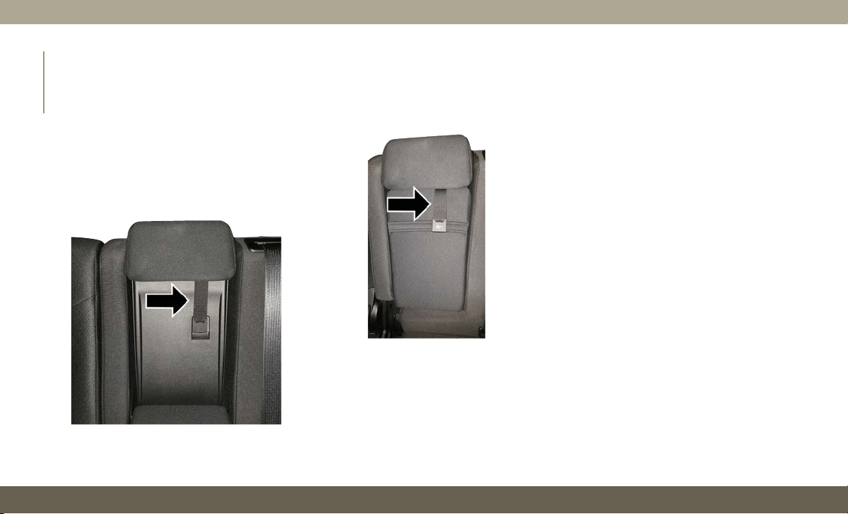
Vehicle With A Center Arm Rest Tether
For rear-facing child restraints secured in the
center seat position with the vehicle seat
belts, the rear center seat position has an
armrest tether that secures the arm rest in
the upward position.
1. To access the center seat arm rest tether,
first lower the arm rest. The tether is
located behind the armrest and hooked
onto the plastic seat backing.
2. Pull down on the tether to unhook it from
the plastic seat backing.
3. Raise the armrest and attach the tether
hook to the strap located on the front of
the arm rest.
Always follow the directions of the child re-
straint manufacturer when installing your child
restraint. Not all child restraint systems will be
installed as described here.
To Install A LATCH-Compatible Child
Restraint
If the selected seating position has a Switch-
able Automatic Locking Retractor (ALR) seat
belt, stow the seat belt, following the instruc-
tions below. See the section “Installing Child
Restraints Using the Vehicle Seat Belt” to
check what type of seat belt each seating
position has.
1. Loosen the adjusters on the lower straps
and on the tether strap of the child seat so
that you can more easily attach the hooks
or connectors to the vehicle anchorages.
2. Place the child seat between the lower
anchorages for that seating position. For
some second row seats, you may need to
recline the seat and / or raise the head
restraint (if adjustable) to get a better fit.
If the rear seat can be moved forward and
rearward in the vehicle, you may wish to
move it to its rear-most position to make
room for the child seat. You may also
move the front seat forward to allow more
room for the child seat.
Center Seat Position Arm Rest Tether
Center Seat Position Arm Rest Tether
SAFETY
136

3. Attach the lower hooks or connectors of
the child restraint to the lower anchorages
in the selected seating position.
4. If the child restraint has a tether strap,
connect it to the top tether anchorage.
See the section “Installing Child Re-
straints Using the Top Tether Anchorage”
for directions to attach a tether anchor.
5. Tighten all of the straps as you push the
child restraint rearward and downward
into the seat. Remove slack in the straps
according to the child restraint manufac-
turer’s instructions.
6. Test that the child restraint is installed
tightly by pulling back and forth on the
child seat at the belt path. It should not
move more than 1 inch (25.4 mm) in any
direction.
How To Stow An Unused Switchable-ALR
(ALR) Seat Belt:
When using the LATCH attaching system to
install a child restraint, stow all ALR seat
belts that are not being used by other occu-
pants or being used to secure child restraints.
An unused belt could injure a child if they
play with it and accidentally lock the seat belt
retractor. Before installing a child restraint
using the LATCH system, buckle the seat belt
behind the child restraint and out of the
child’s reach. If the buckled seat belt inter-
feres with the child restraint installation, in-
stead of buckling it behind the child re-
straint, route the seat belt through the child
restraint belt path and then buckle it. Do not
lock the seat belt. Remind all children in the
vehicle that the seat belts are not toys and
that they should not play with them.
WARNING!
• Improper installation of a child restraint
to the LATCH anchorages can lead to
failure of the restraint. The child could
be badly injured or killed. Follow the
child restraint manufacturer’s directions
exactly when installing an infant or child
restraint.
• Child restraint anchorages are designed
to withstand only those loads imposed
by correctly-fitted child restraints. Un-
der no circumstances are they to be used
for adult seat belts, harnesses, or for
attaching other items or equipment to
the vehicle.
137
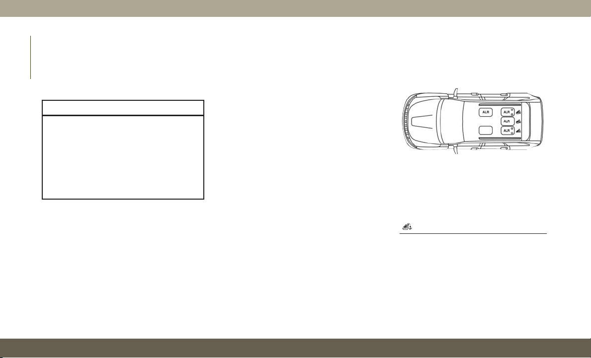
Installing Child Restraints Using The
Vehicle Seat Belt
Child restraint systems are designed to be
secured in vehicle seats by lap belts or the
lap belt portion of a lap/shoulder belt.
WARNING!
• Improper installation or failure to prop-
erly secure a child restraint can lead to
failure of the restraint. The child could
be badly injured or killed.
• Follow the child restraint manufactur-
er’s directions exactly when installing an
infant or child restraint.
The seat belts in the passenger seating posi-
tions are equipped with a Switchable Auto-
matic Locking Retractor (ALR) that is de-
signed to keep the lap portion of the seat belt
tight around the child restraint so that it is
not necessary to use a locking clip. The ALR
retractor can be “switched” into a locked
mode by pulling all of the webbing out of the
retractor and then letting the webbing retract
back into the retractor. If it is locked, the ALR
will make a clicking noise while the webbing
is pulled back into the retractor.
R
efer to the “Automatic Locking Mode” de-
scription in “Switchable Automatic Locking
Retractors (ALR)” under “Occupant Restraint
Systems” for additional information on ALR.
Please see the table below and the following
sections for more information.
Lap/Shoulder Belt Systems For Installing
Child Restraints In This Vehicle
Automatic Locking Retractor (ALR)
Locations
ALR = Switchable Automatic Locking
Retractor
Top Tether Anchorage Symbol
SAFETY
138

Frequently Asked Questions About Installing Child Restraints With Seat Belts
What is the weight limit (child’s weight + weight of the
child restraint) for using the Tether Anchor with the
seat belt to attach a forward facing child restraint?
Weight limit of the
Child Restraint
Always use the tether anchor when using the seat belt
to install a forward facing child restraint, up to the
recommended weight limit of the child restraint.
Can the rear-facing child restraint touch the back of
the front passenger seat?
Yes
Contact between the front passenger seat and the
child restraint is allowed, if the child restraint
manufacturer also allows contact.
Can the rear head restraints be removed? Yes
The head restraint may be removed in only the center
seating position if it interferes with the installation of
the child restraint.
Refer to “Head Restraints” in “Getting To Know Your
Vehicle” for further information.
Can the buckle stalk be twisted to tighten the seat belt
against the belt path of the child restraint?
No
Do not twist the buckle stalk in a seating position with
an ALR retractor.
139

Installing A Child Restraint With A Switch-
able Automatic Locking Retractor (ALR):
Child restraint systems are designed to be
secured in vehicle seats by lap belts or the
lap belt portion of a lap/shoulder belt.
WARNING!
• Improper installation or failure to prop-
erly secure a child restraint can lead to
failure of the restraint. The child could
be badly injured or killed.
• Follow the child restraint manufactur-
er’s directions exactly when installing an
infant or child restraint.
1. Place the child seat in the center of the
seating position. For some second row
seats, you may need to recline the seat
and/or raise the head restraint (if adjust-
able) to get a better fit. If the rear seat can
be moved forward and rearward in the
vehicle, you may wish to move it to its
rear-most position to make room for the
child seat. You may also move the front
seat forward to allow more room for the
child seat.
2. Pull enough of the seat belt webbing from
the retractor to pass it through the belt
path of the child restraint. Do not twist the
belt webbing in the belt path.
3. Slide the latch plate into the buckle until
you hear a “click.”
4. Pull on the webbing to make the lap
portion tight against the child seat.
5. To lock the seat belt, pull down on the
shoulder part of the belt until you have
pulled all the seat belt webbing out of the
retractor. Then, allow the webbing to re-
tract back into the retractor. As the web-
bing retracts, you will hear a clicking
sound. This means the seat belt is now in
the Automatic Locking mode.
6. Try to pull the webbing out of the retractor.
If it is locked, you should not be able to
pull out any webbing. If the retractor is
not locked, repeat step 5.
7. Finally, pull up on any excess webbing to
tighten the lap portion around the child
restraint while you push the child restraint
rearward and downward into the vehicle
seat.
8. If the child restraint has a top tether strap
and the seating position has a top tether
anchorage, connect the tether strap to the
anchorage and tighten the tether strap.
See the section “Installing Child Re-
straints Using the Top Tether Anchorage”
for directions to attach a tether anchor.
9. Test that the child restraint is installed
tightly by pulling back and forth on the
child seat at the belt path. It should not
move more than 1 inch (25.4 mm) in any
direction.
Any seat belt system will loosen with time, so
check the belt occasionally, and pull it tight if
necessary.
SAFETY
140
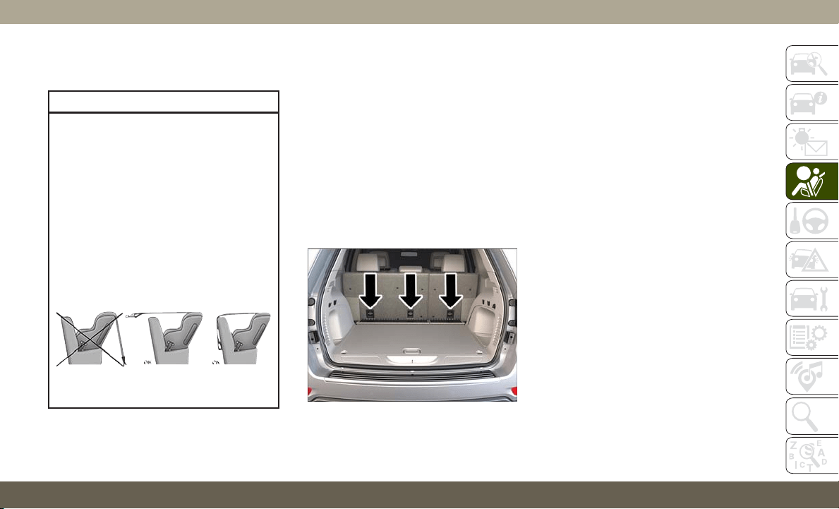
Installing Child Restraints Using The Top
Tether Anchorage:
WARNING!
Do not attach a tether strap for a rear-
facing car seat to any location in front of
the car seat, including the seat frame or a
tether anchorage. Only attach the tether
strap of a rear-facing car seat to the tether
anchorage that is approved for that seating
position, located behind the top of the
vehicle seat. See the section “Lower An-
chors and Tethers for CHildren (LATCH)
Restraint System” for the location of ap-
proved tether anchorages in your vehicle.
1. Look behind the seating position where
you plan to install the child restraint to
find the tether anchorage. You may need
to move the seat forward to provide better
access to the tether anchorage. If there is
no top tether anchorage for that seating
position, move the child restraint to an-
other position in the vehicle if one is
available.
2. T
o access the top tether strap anchorages
behind the rear seat, pull the carpeted floor
panel away from the seat back, this will
expose the top tether strap anchorages.
3. Route the tether strap to provide the most
direct path for the strap between the an-
chor and the child seat. If your vehicle is
equipped with adjustable rear head re-
straints, raise the head restraint, and
where possible, route the tether strap un-
der the head restraint and between the
two posts. If not possible, lower the head
restraint and pass the tether strap around
the outboard side of the head restraint.
4. For the center seating position, route the
tether strap over the seatback and head-
rest then attach the hook to the tether
anchor located on the back of the seat.
Top Tether Strap Anchorage
(Located On Seatback)
141
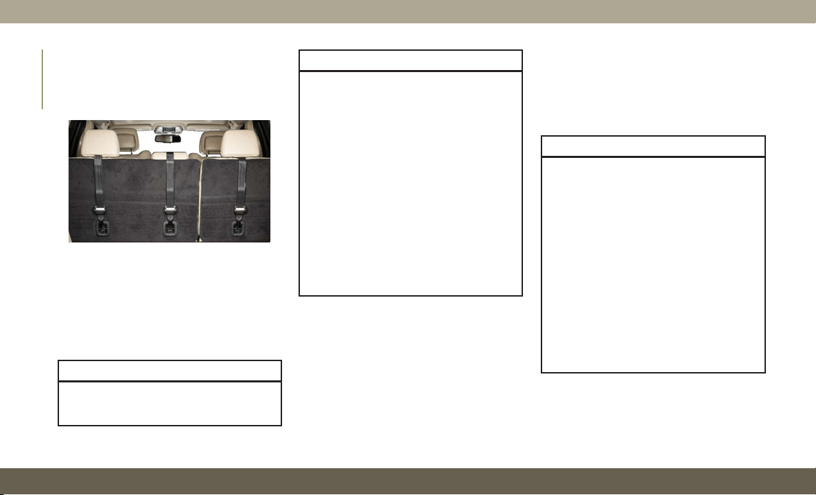
5. Attach the tether strap hook of the child
restraint to the top tether anchorage as
shown in the diagram.
6. Remove slack in the tether strap accord-
ing to the child restraint manufacturer’s
instructions.
WARNING!
• The top tether anchorages are not vis-
ible until the gap panel is folded down.
WARNING!
Do not use the visible cargo tie down
hooks, located on the floor behind the
seats, to attach a child restraint tether
anchor.
• An incorrectly anchored tether strap
could lead to increased head motion and
possible injury to the child. Use only the
anchorage position directly behind the
child seat to secure a child restraint top
tether strap.
• If your vehicle is equipped with a split
rear seat, make sure the tether strap
does not slip into the opening between
the seatbacks as you remove slack in
the strap.
Transporting Pets
Air Bags deploying in the front seat could harm
your pet. An unrestrained pet will be thrown
about and possibly injured, or injure a passen-
ger during panic braking or in a collision.
Pets should be restrained in the rear seat
(if equipped) in pet harnesses or pet carriers
that are secured by seat belts.
SAFETY TIPS
Transporting Passengers
NEVER TRANSPORT PASSENGERS IN THE
CARGO AREA.
WARNING!
• Do not leave children or animals inside
parked vehicles in hot weather. Interior
heat build-up may cause serious injury
or death.
• It is extremely dangerous to ride in a
cargo area, inside or outside of a vehicle.
In a collision, people riding in these
areas are more likely to be seriously
injured or killed.
• Do not allow people to ride in any area of
your vehicle that is not equipped with
seats and seat belts.
• Be sure everyone in your vehicle is in a
seat and using a seat belt properly.
Top Tether Strap Mounting
SAFETY
142
Exhaust Gas
WARNING!
Exhaust gases can injure or kill. They con-
tain carbon monoxide (CO), which is col-
orless and odorless. Breathing it can make
you unconscious and can eventually poi-
son you. To avoid breathing (CO), follow
these safety tips:
• Do not run the engine in a closed garage
or in confined areas any longer than
needed to move your vehicle in or out of
the area.
• If you are required to drive with the
trunk/liftgate/rear doors open, make sure
that all windows are closed and the cli-
mate control BLOWER switch is set at
high speed. DO NOT use the recircula-
tion mode.
• If it is necessary to sit in a parked vehicle
with the engine running, adjust your
heating or cooling controls to force out-
side air into the vehicle. Set the blower
at high speed.
The best protection against carbon monoxide
entry into the vehicle body is a properly main-
tained engine exhaust system.
Whenever a change is noticed in the sound of
the exhaust system, when exhaust fumes can
be detected inside the vehicle, or when the
underside or rear of the vehicle is damaged,
have a competent mechanic inspect the com-
plete exhaust system and adjacent body ar-
eas for broken, damaged, deteriorated, or
mispositioned parts. Open seams or loose
connections could permit exhaust fumes to
seep into the passenger compartment. In
addition, inspect the exhaust system each
time the vehicle is raised for lubrication or oil
change. Replace as required.
Safety Checks You Should Make Inside
The Vehicle
Seat Belts
Inspect the seat belt system periodically,
checking for cuts, frays, and loose parts. Dam-
aged parts must be replaced immediately. Do
not disassemble or modify the system.
Front seat belt assemblies must be replaced
after a collision. Rear seat belt assemblies
must be replaced after a collision if they have
been damaged (i.e., bent retractor, torn web-
bing, etc.). If there is any question regarding
seat belt or retractor condition, replace the
seat belt.
Air Bag Warning Light
The Air Bag warning light will turn on for
four to eight seconds as a bulb check when
the ignition switch is first turned to ON/RUN.
If the light is either not on during starting,
stays on, or turns on while driving, have the
system inspected at an authorized dealer as
soon as possible. After the bulb check, this
light will illuminate with a single chime when
a fault with the Air Bag System has been
detected. It will stay on until the fault is
removed. If the light comes on intermittently
or remains on while driving, have an autho-
rized dealer service the vehicle immediately.
Refer to “Occupant Restraint Systems” in
“Safety” for further information.
143
Defroster
Check operation by selecting the defrost
mode and place the blower control on high
speed. You should be able to feel the air
directed against the windshield. See an au-
thorized dealer for service if your defroster is
inoperable.
Floor Mat Safety Information
Always use floor mats designed to fit your
vehicle. Only use a floor mat that does not
interfere with the operation of the accelera-
tor, brake or clutch pedals. Only use a floor
mat that is securely attached using the floor
mat fasteners so it cannot slip out of position
and interfere with the accelerator, brake or
clutch pedals or impair safe operation of your
vehicle in other ways.
WARNING!
An improperly attached, damaged, folded,
or stacked floor mat, or damaged floor mat
fasteners may cause your floor mat to
interfere with the accelerator, brake, or
WARNING!
clutch pedals and cause a loss of vehicle
control. To prevent SERIOUS INJURY or
DEATH:
• ALWAYS securely attach
your floor
mat using the floor mat fasteners. DO
NOT install your floor mat upside down
or turn your floor mat over. Lightly pull to
confirm mat is secured using the floor
mat fasteners on a regular basis.
• ALWAYS REMOVE THE EXISTING
FLOOR MAT FROM THE VEHICLE
before installing any other floor mat.
NEVER install or stack an additional
floor mat on top of an existing floor mat.
• ONLY install floor mats designed to fit
your vehicle. NEVER install a floor mat
that cannot be properly attached and
secured to your vehicle. If a floor mat
needs to be replaced, only use a FCA
approved floor mat for the specific
make, model, and year of your vehicle.
• ONLY use the driver’s side floor mat on
the driver’s side floor area. To check for
interference, with the vehicle properly
parked with the engine off, fully depress
WARNING!
the accelerator, the brake, and the
clutch pedal (if present) to check for
interference. If your floor mat interferes
with the operation of any pedal, or is not
secure to the floor, remove the floor mat
from the vehicle and place the floor mat
in your trunk.
• ONLY use the passenger’s side floor mat
on the passenger’s side floor area.
• ALWAYS make sure objects cannot fall
or slide into the driver’s side floor area
when the vehicle is moving. Objects can
become trapped under accelerator,
brake, or clutch pedals and could cause
a loss of vehicle control.
• NEVER place any objects under the floor
mat (e.g., towels, keys, etc.). These ob-
jects could change the position of the
floor mat and may cause interference
with the accelerator, brake, or clutch
pedals.
• If the vehicle carpet has been removed
and re-installed, always properly attach
carpet to the floor and check the floor
mat fasteners are secure to the vehicle
SAFETY
144
WARNING!
carpet. Fully depress each pedal to
check for interference with the accelera-
tor, brake, or clutch pedals then re-
install the floor mats.
• It is recommended to only use mild soap
and water to clean your floor mats. After
cleaning, always check your floor mat
has been properly installed and is se-
cured to your vehicle using the floor mat
fasteners by lightly pulling mat.
Periodic Safety Checks You Should Make
Outside The Vehicle
Tires
Examine tires for excessive tread wear and
uneven wear patterns. Check for stones,
nails, glass, or other objects lodged in the
tread or sidewall. Inspect the tread for cuts
and cracks. Inspect sidewalls for cuts,
cracks, and bulges. Check the wheel nuts for
tightness. Check the tires (including spare)
for proper cold inflation pressure.
Lights
Have someone observe the operation of brake
lights and exterior lights while you work the
controls. Check turn signal and high beam
indicator lights on the instrument panel.
Door Latches
Check for proper closing, latching, and locking.
Fluid Leaks
Check area under the vehicle after overnight
parking for fuel, coolant, oil, or other fluid
leaks. Also, if gasoline fumes are detected
or if fuel, or brake fluid leaks are suspected.
The cause should be located and corrected
immediately.
WARNING!
To prevent SERIOUS INJURY or DEATH
when using “Track-Use” parts and equip-
ment:
• NEVER use any “Track-Use” equipment
on public roads. FCA US LLC does not
authorize the use of “Track-Use” equip-
ment on public roads.
WARNING!
• The intended use of “Track-Use” parts is
for race vehicles on race tracks. To help
ensure the safety of the race driver, en-
gineers should supervise the installation
of “Track-Use” parts.
• FCA US LLC does not authorize the in-
stallation or use of any part noted as
“Track-Use” on any new vehicle prior to
its first retail sale.
WARNING!
To prevent SERIOUS INJURY or DEATH:
• ALWAYS remove any “Track-Use” equip-
ment before driving on public roads.
• ALWAYS properly use your three-point
seat belts when driving on public roads.
• In a collision, you and your passengers
can suffer much greater injuries if you
are not properly buckled up. You can
strike the interior of your vehicle or other
passengers, or you can be thrown out of
the vehicle.
145

STARTING THE ENGINE —
GAS
Before starting your vehicle, adjust your seat,
adjust the inside and outside mirrors, fasten
your seat belt, and if present, instruct all
other occupants to buckle their seat belts.
WARNING!
• Before exiting a vehicle, always come to
a complete stop, then shift the auto-
matic transmission into PARK and apply
the parking brake.
• Always make sure the keyless ignition
node is in the OFF mode, key fob is
removed from the vehicle and vehicle is
locked.
• Never leave children alone in a vehicle,
or with access to an unlocked vehicle.
Leaving children in a vehicle unattended
is dangerous for a number of reasons.
A child or others could be seriously or
fatally injured. Children should be
warned not to touch the parking brake,
brake pedal or the gear selector.
WARNING!
• Do not leave the key fob in or near the
vehicle, or in a location accessible to
children, and do not leave the ignition of
a vehicle equipped with Keyless Enter-
N-Go in the ACC or ON/RUN mode. A
child could operate power windows,
other controls, or move the vehicle.
• Do not leave children or animals inside
parked vehicles in hot weather. Interior
heat build-up may cause serious injury
or death.
Automatic Transmission
The gear selector must be in the NEUTRAL or
PARK position before you can start the en-
gine. Apply the brakes before shifting into
any driving gear.
CAUTION!
Damage to the transmission may occur if
the following precautions are not ob-
served:
CAUTION!
• Do not shift from REVERSE, PARK, or
NEUTRAL into any forward gear when
the engine is above idle speed.
• Shift into PARK only after the vehicle
has come to a complete stop.
• Shift into or out of REVERSE only after
the vehicle has come to a complete stop
and the engine is at idle speed.
• Before shifting into any gear, make sure
your foot is firmly on the brake pedal.
Normal Starting
To Turn On The Engine Using The ENGINE
START/STOP Button
1. The transmission must be in PARK or
NEUTRAL.
2. Press and hold the brake pedal while
pushing the ENGINE START/STOP button
once.
3. The system takes over and attempts to
start the vehicle. If the vehicle fails to
start, the starter will disengage automati-
cally after 10 seconds.
STARTING AND OPERATING
146

4. If you wish to stop the cranking of the
engine prior to the engine starting, push
the button again.
NOTE:
Normal starting of either a cold or a warm
engine is obtained without pumping or press-
ing the accelerator pedal.
To Turn Off The Engine Using ENGINE
START/STOP Button
1. Place the gear selector in PARK, then
push and release the ENGINE START/
STOP button.
2. The ignition will return to the OFF mode.
3. If the gear selector is not in PARK (with
vehicle stopped) and the ENGINE START/
STOP button is pushed once, the trans-
mission will automatically select PARK
and the engine will turn off, however the
ignition will remain in the ACC mode (NOT
the OFF mode). Never leave a vehicle out
of the PARK position, or it could roll.
4. If the gear selector is in NEUTRAL, and
the vehicle speed is below 5 mph
(8 km/h), pushing the START/STOP but-
ton once will turn the engine off. The
ignition will remain in the ACC mode.
5. If the vehicle speed is above 5 mph
(8 km/h), the ENGINE START/STOP but-
ton must be held for two seconds (or three
short pushes in a row) to turn the engine
off. The ignition will remain in the ACC
mode (NOT the OFF mode) if the engine is
turned off when the transmission is not in
PARK.
NOTE:
The system will automatically time out and
the ignition will cycle to the OFF mode after
30 minutes of inactivity if the ignition is left
in the ACC or RUN (engine not running) mode
and the transmission is in PARK.
ENGINE START/STOP Button Functions —
With Driver’s Foot OFF The Brake Pedal
(In PARK Or NEUTRAL Position)
The ENGINE START/STOP button operates
similar to an ignition switch. It has three
modes: OFF, ACC, and RUN. To change the
ignition modes without starting the vehicle
and use the accessories, follow these steps:
1.
Starting with the ignition in the OFF mode,
2.
Push the ENGINE START/STOP button
once to place the ignition to the ACC mode
(instrument cluster will display “ACC”),
3. Push the ENGINE START/STOP button a
second time to place the ignition to the
RUN mode (instrument cluster will dis-
play “ON/RUN”),
4. Push the ENGINE START/STOP button a
third time to return the ignition to the OFF
mode (instrument cluster will display
“OFF”).
147

NOTE:
Only press one pedal at a time while driving
the vehicle. Torque performance of the ve-
hicle could be reduced if both pedals are
pressed at the same time. If pressure is
detected on both pedals simultaneously, a
warning message will display in the instru-
ment cluster. For further information, refer to
“Instrument Cluster Display” in “Getting To
Know Your Instrument Panel”.
AutoPark
AutoPark is a supplemental feature to assist
in placing the vehicle in PARK should the
situations on the following pages occur. It is a
back up system and should not be relied
upon as the primary method by which the
driver shifts the vehicle into PARK.
The conditions under which AutoPark will
engage are outlined on the following pages.
WARNING!
• Driver inattention could lead to failure to
place the vehicle in PARK. ALWAYS DO
A VISUAL CHECK that your vehicle is in
PARK by verifying that a solid (not blink-
WARNING!
ing) “P” is indicated in the instrument
cluster display and on the gear selector.
If the "P" indicator is blinking, your ve-
hicle is not in PARK. As an added pre-
caution, always apply the parking brake
when exiting the vehicle.
• AutoPark is a supplemental feature. It is
not designed to replace the need to shift
your vehicle into PARK. It is a back up
system and should not be relied upon as
the primary method by which the driver
shifts the vehicle into PARK.
If the vehicle is not in PARK and the driver turns
off the engine, the vehicle may AutoPark.
AutoPark will engage when all of these con-
ditions are met:
• Vehicle is equipped with an 8-speed trans-
mission
• Vehicle is not in PARK
• Vehicle Speed is 1.2 MPH (1.9 km/h) or
less
• Ignition switched from RUN to ACC
NOTE:
For Keyless Go equipped vehicles, The en-
gine will turn off and the ignition switch will
change to ACC mode. After 30 minutes the
ignition switches to OFF automatically, un-
less the driver turns the ignition switch OFF.
If the vehicle is not in PARK and the driver exits
the vehicle with the engine running, the vehicle
may AutoPark.
AutoPark will engage when all of these con-
ditions are met:
• Vehicle is equipped with an 8-speed trans-
mission
• Vehicle is not in PARK
• Vehicle Speed is 1.2 MPH (1.9 km/h) or
less
• Driver’s seat belt is unbuckled
• Driver’s door is ajar
• Brake Pedal is not depressed
The MESSAGE “AutoPark Engaged Shift to P
then Shift to Gear”will display in the instru-
ment cluster.
STARTING AND OPERATING
148
NOTE:
In some cases the ParkSense graphic will be
displayed in the instrument cluster. In these
cases, the shifter must be returned to “P” to
select desired gear.
If the driver shifts into PARK while moving, the
vehicle may AutoPark.
AutoPark will engage ONLY when vehicle
speed is 1.2 MPH (1.9 km/h) or less.
The MESSAGE “Vehicle Speed is Too High to
Shift to P”will be displayed in the instrument
cluster if vehicle speed is above 1.2 MPH
(1.9 km/h).
WARNING!
If vehicle speed is above 1.2 MPH
(1.9 km/h), the transmission will default to
NEUTRAL until the vehicle speed drops
below 1.2 MPH (1.9 km). A vehicle left in
the NEUTRAL position can roll. As an
added precaution, always apply the park-
ing brake when exiting the vehicle.
4WD LOW — If Equipped
AutoPark will be disabled when operating the
vehicle in 4WD LOW.
The MESSAGE “AutoPark Disabled” will be
displayed in the instrument cluster.
Additional customer warnings will be given
when both of these conditions are met:
• Vehicle is not in PARK
• Driver’s Door is ajar
The MESSAGE “AutoPark Not Engaged” will
be displayed in the instrument cluster. A
warning chime will continue until you shift
the vehicle into PARK or the Driver’s Door is
closed.
ALWAYS DO A VISUAL CHECK that your vehicle
is in PARK by looking for the "P" in the
instrument cluster display and on the shifter.
As an added precaution, always apply the
parking brake when exiting the vehicle.
STARTING THE ENGINE —
3.0L DIESEL ENGINE
Before starting your vehicle, adjust your seat,
both inside and outside mirrors, and fasten
your seat belts.
The starter is allowed to crank for up to
30-second intervals. Waiting a few minutes
between such intervals will protect the starter
from overheating.
WARNING!
• Before exiting a vehicle, always come to
a complete stop, then shift the auto-
matic transmission into PARK and apply
the parking brake.
• Always make sure the keyless ignition
node is in the OFF mode, key fob is
removed from the vehicle and vehicle is
locked.
• Never leave children alone in a vehicle,
or with access to an unlocked vehicle.
Leaving children in a vehicle unattended
is dangerous for a number of reasons.
149

WARNING!
A child or others could be seriously or
fatally injured. Children should be
warned not to touch the parking brake,
brake pedal or the gear selector.
• Do not leave the key fob in or near the
vehicle, or in a location accessible to
children, and do not leave the ignition of
a vehicle equipped with Keyless Enter-
N-Go in the ACC or ON/RUN mode. A
child could operate power windows,
other controls, or move the vehicle.
• Do not leave children or animals inside
parked vehicles in hot weather. Interior
heat build-up may cause serious injury
or death.
NOTE:
Engine start up in very low ambient tempera-
ture could result in evident white smoke. This
condition will disappear as the engine warms
up.
CAUTION!
• The engine is allowed to crank as long as
30 seconds. If the engine fails to start
during this period, please wait at least
two minutes for the starter to cool before
repeating start procedure.
• If the “Water in Fuel Indicator Light”
remains on, DO NOT START engine be-
fore you drain the water from the fuel
filters to avoid engine damage. Refer to
“Draining Fuel/Water Separator Filter”
in “Servicing And Maintenance” in your
Diesel Supplement for further informa-
tion, which can be found with your on-
line Owner’s Information.
Automatic Transmission
Start the engine with the transmission gear
selector in the PARK position. Apply the
brake before shifting to any driving range.
Normal Starting
Observe the instrument panel cluster lights
when starting the engine.
NOTE:
Normal starting of either a cold or a warm
engine is obtained without pumping or press-
ing the accelerator pedal
1. Always apply the parking brake.
2. Press and hold the brake pedal while
pushing the ENGINE START/STOP button
once.
NOTE:
A delay of the start of up to five seconds is
possible under very cold conditions. The
"Wait to Start" telltale will be illuminated
during the pre-heat process, When the
engine Wait To Start light goes off the
engine will automatically crank.
STARTING AND OPERATING
150
CAUTION!
If the “Water in Fuel Indicator Light” re-
mains on, DO NOT START engine before
you drain the water from the fuel filters to
avoid engine damage. Refer to “Draining
Fuel/Water Separator Filter” in “Servicing
And Maintenance” in your Diesel Supple-
ment for further information, which can
be found with your online Owner’s Infor-
mation.
3. The system will automatically engage the
starter to crank the engine. If the vehicle
fails to start, the starter will disengage
automatically after 25 seconds.
4. If you wish to stop the cranking of the
engine prior to the engine starting, push
the button again.
5. Check that the oil pressure warning light
has turned off.
6. Release the parking brake.
NOTE:
Only press one pedal at a time while driving
the vehicle. Torque performance of the ve-
hicle could be reduced if both pedals are
pressed at the same time. If pressure is
detected on both pedals simultaneously, a
warning message will display in the instru-
ment cluster. For further information, refer to
“Instrument Cluster Display” in “Getting To
Know Your Instrument Panel”.
ENGINE BREAK-IN
RECOMMENDATIONS
3.6L & 5.7L Engines
A long break-in period is not required for the
drivetrain (engine, transmission, clutch, and
rear axle) in your new vehicle.
Drive moderately during the first 300 miles
(500 km). After the initial 60 miles (100 km),
speeds up to 50 or 55 mph (80 or 90 km/h) are
desirable.
While cruising, brief full-throttle acceleration
within the limits of local traffic laws contrib-
utes to a good break-in. However, wide-open
throttle acceleration in low gear can be det-
rimental and should be avoided.
The engine oil, transmission fluid, and axle
lubricant installed at the factory is high-
quality and energy-conserving. Oil, fluid, and
lubricant changes should be consistent with
anticipated climate and conditions under
which vehicle operations will occur. For the
recommended viscosity and quality grades,
refer to “Fluids And Lubricants” in "Techni-
cal Specifications”.
CAUTION!
Never use Non-Detergent Oil or Straight
Mineral Oil in the engine or damage may
result.
NOTE:
A new engine may consume some oil during
its first few thousand miles (kilometers) of
operation. This should be considered a nor-
151

mal part of the break-in and not interpreted
as an indication of difficulty. Please check
your oil level with the engine oil indicator
often during the break in period. Add oil as
required.
Diesel Engine
The diesel engine does not require a break-in
period due to its construction. Normal opera-
tion is allowed, providing the following rec-
ommendations are followed:
• Warm up the engine before placing it under
load.
• Do not operate the engine at idle for pro-
longed periods.
• Use the appropriate transmission gear to
prevent engine lugging.
• Observe vehicle oil pressure and tempera-
ture indicators.
• Check the coolant and oil levels frequently.
• Vary throttle position at highway speeds
when carrying or towing significant weight.
NOTE:
Light duty operation such as light trailer
towing or no load operation will extend the
time before the engine is at full efficiency.
Reduced fuel economy and power may be
seen at this time.
The engine oil installed in the engine at the
factory is a high-quality energy conserving
type lubricant. Oil changes should be consis-
tent with anticipated climate conditions un-
der which vehicle operations will occur. The
recommended viscosity and quality grades
are shown under “Fluids And Lubricants” in
"Technical Specifications” in this manual.
NON-DETERGENT OR STRAIGHT MINERAL
OILS MUST NEVER BE USED.
SRT Engines
The following tips will be helpful in obtaining
optimum performance and maximum dura-
bility for your new SRT Vehicle.
Despite modern technology and World Class
manufacturing methods, the moving parts of
the vehicle must still wear in with each other.
This wearing in occurs mainly during the first
500 miles (805 km) and continues through
the first oil change interval.
It is recommended for the operator to observe
the following driving behaviors during the
new vehicle break-in period:
0 to 100 miles (0 to 161 km):
• Do not allow the engine to operate at idle
for an extended period of time.
• Depress the accelerator pedal slowly and
not more than halfway to avoid rapid accel-
eration.
• Avoid aggressive braking.
• Drive with the engine speed less than
3,500 RPM.
• Maintain vehicle speed below 55 mph
(88 km/h) and observe local speed limits.
100 to 300 miles (161 to 483 km):
• Depress the accelerator pedal slowly and
not more than halfway to avoid rapid accel-
eration in lower gears (1st to 3rd gears).
• Avoid aggressive braking.
STARTING AND OPERATING
152
• Drive with the engine speed less than
5,000 RPM.
• Maintain vehicle speed below 70 mph
(112 km/h) and observe local speed limits.
300 to 500 miles (483 to 805 km):
• Exercise the full engine rpm range, shifting
manually (paddles or gear shift) at higher
rpms when possible.
• Do not perform sustained operation with
the accelerator pedal at wide open throttle.
• Maintain vehicle speed below 85 mph
(136 km/h) and observe local speed limits.
For the first 1500 miles (2414 km):
• Do not participate in track events, sport
driving schools, or similar activities during
the first 1500 mi (2414 km).
NOTE:
Check engine oil with every refueling and add if
necessary. Oil and fuel consumption may be
higher through the first oil change interval.
Running the engine with an oil level below the
add mark can cause severe engine damage.
STOP/START SYSTEM —
IF EQUIPPED
The Stop/Start function is developed to re-
duce fuel consumption. The system will stop
the engine automatically during a vehicle
stop if the required conditions are met. Re-
leasing the brake pedal or pressing the accel-
erator pedal will automatically re-start the
engine.
This vehicle has been upgraded with a heavy
duty starter, enhanced battery, and other up-
graded engine parts, to handle the additional
engine starts.
Automatic Mode
The Stop/Start feature is enabled
after every normal customer en-
gine start. At that time, the sys-
tem will go into STOP/START
READY and if all other conditions are met,
can go into a STOP/START AUTOSTOP AC-
TIVE “Autostop” mode.
To Activate The Autostop Mode, The Following
Must Occur:
• The system must be in STOP/START
READY state. A STOP/START READY mes-
sage will be displayed in the instrument
cluster display within the Stop/Start sec-
tion. Refer to “Instrument Cluster” in “Get-
ting To Know Your Instrument Panel” in
your Owner’s Manual for further informa-
tion.
• The vehicle must be completely stopped.
• The shifter must be in a forward gear and
the brake pedal depressed.
The engine will shut down, the tachometer
will move to the zero position and the Stop/
Start telltale will illuminate indicating you
are in Autostop. Customer settings will be
maintained upon return to an engine running
condition.
Refer to the “Stop/Start System” in the
“Starting And Operating” section located in
your Owner’s Manual for further information.
153

Possible Reasons The Engine Does Not
Autostop
Prior to engine shut down, the system will
check many safety and comfort conditions to
see if they are fulfilled. Detailed information
about the operation of the Stop/Start system
may be viewed in the instrument cluster
display Stop/Start Screen. In the following
situations, the engine will not stop:
• Driver’s seat belt is not buckled.
• Driver’s door is not closed.
• Battery temperature is too warm or cold.
• Battery charge is low.
• The vehicle is on a steep grade.
• Cabin heating or cooling is in process and
an acceptable cabin temperature has not
been achieved.
• HVAC is set to full defrost mode at a high
blower speed.
• HVAC set to MAX A/C.
• Engine has not reached normal operating
temperature.
• The transmission is not in a forward gear.
• Hood is open.
• Vehicle is in 4LO transfer case mode.
• Brake pedal is not pressed with sufficient
pressure.
Other Factors Which Can Inhibit Autostop
Include:
• Accelerator pedal input.
• Engine temp too high.
• 5 mph (8 km/h) threshold not achieved
from previous AUTOSTOP.
• Steering angle beyond threshold.
• ACC is on and speed is set.
It may be possible for the vehicle to be driven
several times without the STOP/START sys-
tem going into a STOP/START READY state
under more extreme conditions of the items
listed above.
T
o Start The Engine While In Autostop
Mode
W
hile in a forward gear, the engine will start
when the brake pedal is released or the throttle
pedal is depressed. The transmission will au-
tomatically re-engage upon engine restart.
Conditions That Will Cause The Engine To Start
Automatically While In Autostop Mode:
• The transmission selector is moved out of
DRIVE.
• To maintain cabin temperature comfort.
• HVAC is set to full defrost mode.
• HVAC system temperature or fan speed is
manually adjusted.
• Battery voltage drops too low.
• Low brake vacuum (e.g. after several brake
pedal applications).
• STOP/START OFF switch is pushed.
• A STOP/START system error occurs.
• 4WD system is put into 4LO mode.
STARTING AND OPERATING
154
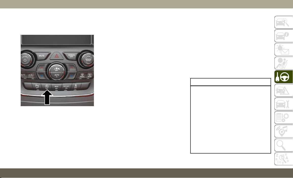
To Manually Turn Off The Stop/Start
System
1. Push the STOP/START OFF switch (lo-
cated on the switch bank). The light on
the switch will illuminate.
2. The “STOP/START OFF” message will ap-
pear in instrument cluster display within
the Stop/Start section. Refer to “Instru-
ment Cluster” in “Getting To Know Your
Instrument Panel” in your Owner’s
Manual for further information.
3. At the next vehicle stop (after turning off
the STOP/START system), the engine will
not be stopped.
4. The STOP/START system will reset itself
back to an ON condition every time the
ignition is turned off and back on.
To Manually Turn On The Stop/Start
System
Push the STOP/START OFF switch (located
on the switch bank). The light on the switch
will turn off.
For complete details on the Stop/Start Sys-
tem refer to the “Stop/Start System” in the
“Starting And Operating” section located in
your Owner’s Manual for further information.
System Malfunction
If there is a malfunction in the STOP/START
system, the system will not shut down the
engine. A “SERVICE STOP/START SYSTEM”
message will appear in the instrument cluster
display. Refer to “Instrument Cluster Dis-
play“ in “Getting to Know Your Instrument
Panel” for further information.
If the “SERVICE STOP/START SYSTEM”
message appears in the instrument cluster
display, have the system checked by an au-
thorized dealer.
AUTOMATIC TRANSMISSION
WARNING!
•
Never use the PARK position as a substi-
tute for the parking brake. Always apply
the parking brake fully when exiting the
vehicle to guard against vehicle move-
ment and possible injury or damage.
• Your vehicle could move and injure you
and others if it is not in PARK. Check by
trying to move the transmission gear
selector out of PARK with the brake
pedal released. Make sure the transmis-
sion is in PARK before exiting the ve-
hicle.
STOP/START Off Switch
155

WARNING!
• The transmission may not engage PARK
if the vehicle is moving. Always bring the
vehicle to a complete stop before shift-
ing to PARK, and verify that the trans-
mission gear position indicator solidly
indicates PARK (P) without blinking. En-
sure that the vehicle is completely
stopped, and the PARK position is prop-
erly indicated, before exiting the ve-
hicle.
• It is dangerous to shift out of PARK or
NEUTRAL if the engine speed is higher
than idle speed. If your foot is not firmly
pressing the brake pedal, the vehicle
could accelerate quickly forward or in
reverse. You could lose control of the
vehicle and hit someone or something.
Only shift into gear when the engine is
idling normally and your foot is firmly
pressing the brake pedal.
•
Unintended movement of a vehicle could
injure those in or near the vehicle. As with
all vehicles, you should never exit a ve-
hicle while the engine is running. Before
exiting a vehicle, always come to a com-
WARNING!
plete stop, then apply the parking brake,
shift the transmission into PARK, and
turn the ignition OFF. When the ignition is
in the OFF mode, the transmission is
locked in PARK, securing the vehicle
against unwanted movement.
• When exiting the vehicle, always make
sure the ignition is in the OFF mode,
remove the key fob from the vehicle, and
lock the vehicle.
• Never leave children alone in a vehicle,
or with access to an unlocked vehicle.
Allowing children to be in a vehicle un-
attended is dangerous for a number of
reasons. A child or others could be seri-
ously or fatally injured. Children should
be warned not to touch the parking
brake, brake pedal or the transmission
gear selector.
• Do not leave the key fob in or near the
vehicle (or in a location accessible to
children), and do not leave the ignition
in the ACC or ON/RUN mode. A child
could operate power windows, other con-
trols, or move the vehicle.
CAUTION!
Damage to the transmission may occur if
the following precautions are not observed:
• Shift into or out of PARK or REVERSE
only after the vehicle has come to a
complete stop.
• Do not shift between PARK, REVERSE,
NEUTRAL, or DRIVE when the engine is
above idle speed.
• Before shifting into any gear, make sure
your foot is firmly pressing the brake
pedal.
NOTE:
You must press and hold the brake pedal
while shifting out of PARK.
Ignition Park Interlock
This vehicle is equipped with an Ignition Park
Interlock which requires the transmission to
be in PARK before the ignition can be turned
to the OFF mode. This helps the driver avoid
inadvertently leaving the vehicle without
placing the transmission in PARK. This sys-
tem also locks the transmission in PARK
whenever the ignition is in the OFF mode.
STARTING AND OPERATING
156
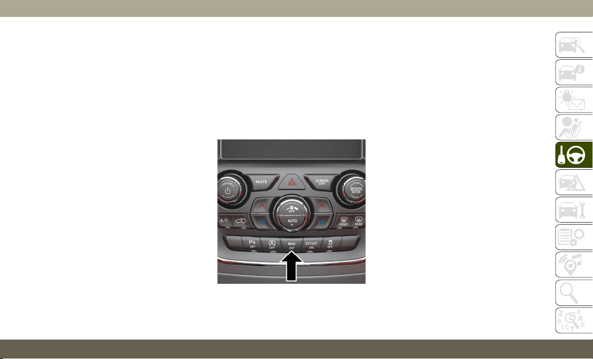
NOTE:
The transmission is NOT locked in PARK
when the ignition is in the ACC mode (even
though the engine will be off). Ensure that
the transmission is in PARK, and the ignition
is OFF (not in ACC mode) before exiting the
vehicle.
Brake/Transmission Shift Interlock
System
This vehicle is equipped with a Brake Trans-
mission Shift Interlock system (BTSI) that
holds the transmission gear selector in PARK
unless the brakes are applied. To shift the
transmission out of PARK, the engine must
be running and the brake pedal must be
pressed. The brake pedal must also be
pressed to shift from NEUTRAL into DRIVE
or REVERSE when the vehicle is stopped or
moving at low speeds.
Fuel Economy (ECO) Mode
The Fuel Economy (ECO) mode can improve
the vehicle's overall fuel economy during nor-
mal driving conditions. Push the “ECO”
switch in the center stack of the instrument
panel to activate or disable ECO mode. A light
on the switch indicates when ECO mode is
disabled (for regular models) or enabled
(for SRT models).
When the Fuel Economy (ECO) Mode is en-
gaged, the vehicle control systems will change
the following:
• The transmission will upshift sooner and
downshift later.
• The overall driving performance will be
more conservative.
• Vehicles with Quadra-Lift air suspension
will operate in "Aero" mode over a broader
speed range. Refer to the section on
Quadra-Lift for further information.
• In SRT models, the transmission will
launch (from a stop) in second gear, and the
torque converter clutch may engage at
lower engine speeds and remain on longer.
• Some ECO mode functions may be tempo-
rarily inhibited based on temperature and
other factors.
Active Noise Cancellation — If Equipped
Your vehicle is equipped with an Active Noise
Cancellation System. This system uses four
microphones embedded in the headliner to
detect undesirable exhaust noise, which
sometimes occurs when operating in specific
driving conditions such as ECO and Tow
ECO Switch
157
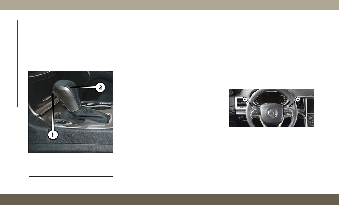
mode. An onboard frequency generator cre-
ates counteracting sound waves through the
audio system to help keep the vehicle quiet.
Eight–Speed Automatic Transmission
Your vehicle is equipped with a fuel efficient
8 speed transmission. The gear selector is
located in the center console.
The transmission gear selector provides
PARK, REVERSE, NEUTRAL, and MANUAL
or SPORT (AutoStick) shift positions. Manual
shifts can be made using the AutoStick
shift control. Toggling the gear selector for-
ward (-) or rearward (+) while in the MANUAL
or SPORT (AutoStick) position (beside the
DRIVE position), or tapping the shift paddles
(+/-), if equipped, will manually select the
transmission gear, and will display the cur-
rent gear in the instrument cluster. Refer to
"AutoStick" in this section for further infor-
mation.
NOTE:
If the gear selector cannot be moved to the
PARK, REVERSE, or NEUTRAL position
(when pushed forward), it is probably in the
AutoStick (+/-) position (beside the DRIVE
position). In AutoStick mode, the transmis-
sion gear (1, 2, 3, etc.) is displayed in the
instrument cluster. Move the gear selector to
the right (into the DRIVE [D] position) for
access to PARK, REVERSE, and NEUTRAL.
AutoStick
AutoStick is a driver-interactive transmission
feature providing manual shift control, giving
you more control of the vehicle. AutoStick
allows you to maximize engine braking, elimi-
nate undesirable upshifts and downshifts,
and improve overall vehicle performance.
This system can also provide you with more
control during passing, city driving, cold slip-
pery conditions, mountain driving, trailer
towing, and many other situations.
Operation
To activate AutoStick mode, move the gear
selector into the MANUAL (M) or SPORT (S)
position (beside the DRIVE position), or tap
one of the shift paddles on the steering wheel
Transmission Gear Selector
1 — Lock Button
2 — Transmission Gear Selector
Shift Paddles
STARTING AND OPERATING
158

(if equipped). Tapping the (-) shift paddle
(if equipped) to enter AutoStick mode will
downshift the transmission to the next lower
gear, while tapping (+) to enter AutoStick
mode will retain the current gear. The current
transmission gear will be displayed in the
instrument cluster. In AutoStick mode, you
can use the gear selector (in the MANUAL
or SPORT position), or the shift paddles
(if equipped), to manually shift the transmis-
sion. Tapping the gear selector forward (-)
while in the MANUAL (M) or SPORT (S)
position, or tapping the (-) shift paddle
(if equipped), will downshift the transmission
to the next lower gear. Tapping the selector
rearward (+) (or tapping the (+) shift paddle,
if equipped) will command an upshift.
NOTE:
The shift paddles (if equipped) may be dis-
abled (or re-enabled, as desired) using the
Uconnect Personal Settings or, in SRT mod-
els, using Drive Modes.
In AutoStick mode, the transmission will
shift up or down when (+/-) is manually se-
lected by the driver (using the gear selector,
or the shift paddles, if equipped), unless an
engine lugging or overspeed condition would
result. It will remain in the selected gear until
another upshift or downshift is chosen, ex-
cept as described below.
• The transmission will automatically down-
shift as the vehicle slows (to prevent engine
lugging) and will display the current gear.
• The transmission will automatically down-
shift to first gear when coming to a stop.
After a stop, the driver should manually
upshift (+) the transmission as the vehicle
is accelerated.
• You can start out, from a stop, in first or
second gear (or third gear, in 4LO range,
Snow mode, or Sand mode). Tapping (+) (at
a stop) will allow starting in second gear.
Starting out in second or third gear can be
helpful in snowy or icy conditions.
•If
a requested downshift would cause the
engine to over-speed, that shift will not occur.
• The system will ignore attempts to upshift
at too low of a vehicle speed.
• Holding the (-) paddle depressed (if
equipped), or holding the gear selector in
the (-) position, will downshift the transmis-
sion to the lowest gear possible at the
current speed.
• Transmission shifting will be more notice-
able when AutoStick is enabled.
• The system may revert to automatic shift
mode if a fault or overheat condition is
detected.
NOTE:
When Selec-Speed or Hill Descent Control is
enabled, AutoStick is not active.
To disengage AutoStick, return the gear se-
lector to the DRIVE position, or press and
hold the (+) shift paddle (if equipped, and
the gear selector is already in DRIVE) until
"D" is once again indicated in the instrument
cluster. You can shift in or out of AutoStick at
any time without taking your foot off the
accelerator pedal.
159
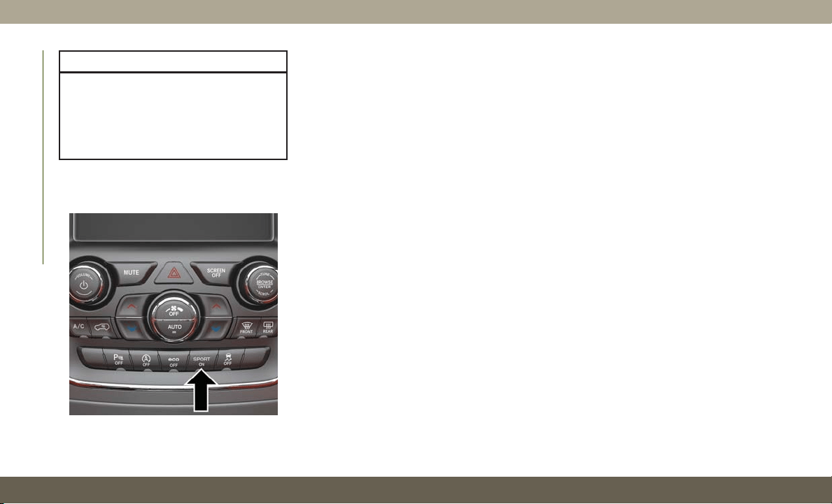
WARNING!
Do not downshift for additional engine
braking on a slippery surface. The drive
wheels could lose their grip and the ve-
hicle could skid, causing a collision or
personal injury.
SPORT MODE — IF EQUIPPED
Your vehicle is equipped with a Sport Mode
feature. This mode is a configuration set up
for typical enthusiast driving. The engine,
transmission, and steering systems are all set
to their SPORT settings. Sport Mode will
provide improved throttle response and modi-
fied shifting for an enhanced driving experi-
ence, as well the greatest amount of steering
feel. This mode may be activated and deac-
tivated by pushing the Sport button on the
instrument panel switch bank.
FOUR WHEEL DRIVE
OPERATION
Quadra-Trac I Operating Instructions/
Precautions — If Equipped
The Quadra-Trac I is a single-speed (HI range
only) transfer case, which provides conve-
nient full-time four-wheel drive. No driver
interaction is required. The Brake Traction
Control (BTC) System, which combines stan-
dard ABS and Traction Control, provides re-
sistance to any wheel that is slipping to allow
additional torque transfer to wheels with trac-
tion.
NOTE:
The Quadra-Trac I system is not appropriate
for conditions where 4WD LOW range is rec-
ommended. Refer to “Off-Road Driving Tips”
in “Starting And Operating” in the Owner’s
Manual.
Quadra-Trac II Operating Instructions/
Precautions — If Equipped
The Quadra-Trac II transfer case is fully au-
tomatic in the normal driving 4WD AUTO
mode. The Quadra-Trac II transfer case pro-
vides three mode positions:
• 4WD HI
• NEUTRAL
• 4WD LOW
This transfer case is fully automatic in the
4WD HI mode.
When additional traction is required, the
4WD LOW position can be used to lock the
front and rear driveshafts together and force
the front and rear wheels to rotate at the
same speed. The 4WD LOW position is in-
tended for loose, slippery road surfaces only.
Sport Mode Button
STARTING AND OPERATING
160
Driving in the 4WD LOW position on dry,
hard-surfaced roads may cause increased tire
wear and damage to driveline components.
When operating your vehicle in 4WD LOW,
the engine speed is approximately three
times that of the 4WD HI position at a given
road speed. Take care not to overspeed the
engine and do not exceed 25 mph (40 km/h).
Proper operation of four-wheel drive vehicles
depends on tires of equal size, type, and
circumference on each wheel. Any difference
will adversely affect shifting and cause dam-
age to the transfer case.
Because four-wheel drive provides improved
traction, there is a tendency to exceed safe
turning and stopping speeds. Do not go faster
than road conditions permit.
WARNING!
You or others could be injured or killed if
you leave the vehicle unattended with the
transfer case in the NEUTRAL position
without first fully engaging the parking
WARNING!
brake. The transfer case NEUTRAL posi-
tion disengages both the front and rear
drive shafts from the powertrain and will
allow the vehicle to roll, even if the trans-
mission is in PARK. The parking brake
should always be applied when the driver
is not in the vehicle.
Shift Positions
For additional information on the appropriate
use of each 4WD system mode position, see
the information below:
4WD AUTO
This range is used on surfaces such as ice,
snow, gravel, sand, and dry hard pavement.
NOTE:
Refer to “Selec-Terrain — If Equipped” fur-
ther on in this section for further information
on the various positions and their intended
usages.
NEUTRAL
This range disengages the driveline from the
powertrain. It is to be used for flat towing
behind another vehicle. Refer to “Recre-
ational Towing” in “Starting And Operating”
for further information.
WARNING!
You or others could be injured or killed if
you leave the vehicle unattended with the
transfer case in the NEUTRAL position
without first fully engaging the parking
brake. The transfer case NEUTRAL posi-
tion disengages both the front and rear
drive shafts from the powertrain and will
allow the vehicle to roll, even if the trans-
mission is in PARK. The parking brake
should always be applied when the driver
is not in the vehicle.
161
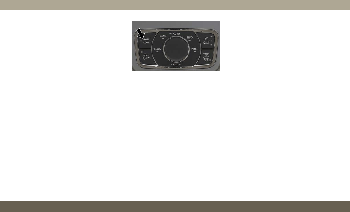
4WD LOW
This range is for low speed four-wheel drive.
It provides an additional gear reduction
which allows for increased torque to be deliv-
ered to both the front and rear wheels while
providing maximum pulling power for loose,
slippery road surfaces only. Do not exceed
25 mph (40 km/h).
NOTE:
Refer to “Selec-Terrain — If Equipped” for
further information on the various positions
and their intended usages.
Shifting Procedures
4WD HI To 4WD LOW
With the vehicle at speeds of 0 to 3 mph (0 to
5 km/h), the ignition switch in the ON posi-
tion or the engine running, shift the transmis-
sion into “N”, and push the “4WD LOW”
button once on the transfer case switch. The
“4WD LOW” indicator light in the instrument
cluster will begin to flash and remain on solid
when the shift is complete.
NOTE:
If shift conditions/interlocks are not met, or a
transfer case motor temperature protection
condition exists, a “For 4x4 Low Slow Below
3 mph (5 km/h) Put Trans in “N” Press
4 Low” message will flash from the instru-
ment cluster display. Refer to “Instrument
Cluster Display” in “Getting To Know Your
Instrument Panel” for further information.
4WD LOW To 4WD HI
With the vehicle at speeds of 0 to 3 mph (0 to
5 km/h), the ignition switch in the ON posi-
tion or the engine running, shift the transmis-
sion into NEUTRAL, and push the “4WD
LOW” button once on the transfer case
switch. The “4WD LOW” indicator light in the
instrument cluster will flash and go out when
the shift is complete.
NOTE:
• If shift conditions/interlocks are not met, or
a transfer case motor temperature protec-
tion condition exists, a “For 4x4 High Slow
Below 3 mph (5 km/h) Put Trans in N push
4 Low” message will flash from the instru-
ment cluster display. Refer to “Instrument
Cluster Display” in “Getting To Know Your
Instrument Panel” for further information.
• Shifting into or out of 4WD LOW is possible
with the vehicle completely stopped; how-
ever, difficulty may occur due to the mating
clutch teeth not being properly aligned.
Several attempts may be required for
clutch teeth alignment and shift comple-
tion to occur. The preferred method is with
the vehicle rolling 0 to 3 mph (0 to 5 km/h).
If the vehicle is moving faster than 3 mph
(5 km/h), the transfer case will not allow
the shift.
Transfer Case Switch
STARTING AND OPERATING
162
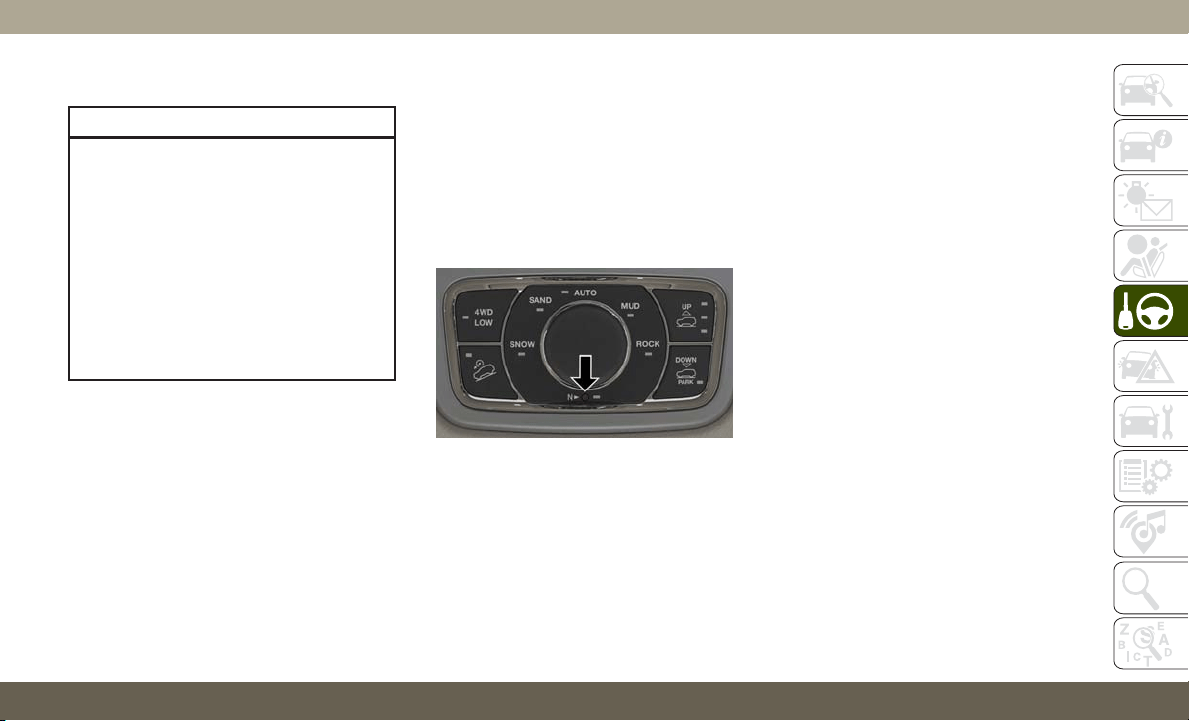
Shifting Into NEUTRAL (N)
WARNING!
You or others could be injured or killed if
you leave the vehicle unattended with the
transfer case in the NEUTRAL (N) position
without first fully engaging the parking
brake. The NEUTRAL (N) position disen-
gages both the front and rear drive shafts
from the powertrain and will allow the
vehicle to roll, even if the transmission is
in PARK. The parking brake should always
be applied when the driver is not in the
vehicle.
1. Bring the vehicle to a complete stop, with
the engine running.
2. Press and hold the brake pedal.
3. Shift the transmission into NEUTRAL.
4. If vehicle is equipped with Quadra-Lift air
suspension, ensure the vehicle is set to
Normal Ride Height.
5. Using a ballpoint pen or similar object,
push and hold the recessed transfer case
NEUTRAL (N) button (located by the se-
lector switch) for four seconds. The light
behind the NEUTRAL (N) symbol will
blink, indicating shift in progress. The
light will stop blinking (stay on solid)
when the shift to NEUTRAL (N) is com-
plete. A “NEUTRAL” message will appear
in the instrument cluster display. Refer to
“Instrument Cluster Display” in “Getting
To Know Your Instrument Panel” for fur-
ther information.
6. After the shift is completed and the NEU-
TRAL (N) light stays on, release the NEU-
TRAL (N) button.
7. Shift the transmission into REVERSE.
8. Release the brake pedal for five seconds
and ensure that there is no vehicle
movement.
9. Press and hold the brake pedal. Shift the
transmission back into NEUTRAL.
10. Firmly apply the parking brake.
11. With the transmission and transfer case
in NEUTRAL, push and hold the EN-
GINE START/STOP button until the en-
gine turns off.
12. Place the transmission gear selector in
PARK. Release the brake pedal.
13. Push the ENGINE STOP/START button
twice (without pressing the brake pedal),
to turn the ignition to the OFF mode.
14. Release the parking brake only when the
vehicle is securely attached to a tow
vehicle.
NOTE:
If shift conditions/interlocks are not met, a
“To Tow Vehicle Safely, Read Neutral Shift
Procedure in Owner’s Manual” message will
flash from the instrument cluster display.
Refer to “Instrument Cluster Display” in
“Getting To Know Your Instrument Panel” for
further information.
NEUTRAL (N) Switch
163

Shifting Out Of NEUTRAL (N)
Use the following procedure to prepare your
vehicle for normal usage.
1. Bring the vehicle to a complete stop.
2. Firmly apply the parking brake.
3. Start the engine.
4. Press and hold the brake pedal.
5. Shift the transmission into NEUTRAL.
6. Using a ballpoint pen or similar object,
push and hold the recessed transfer case
NEUTRAL (N) button (located by the se-
lector switch) for one second.
7.
When the NEUTRAL (N) indicator light
turns off, release the NEUTRAL (N) button.
8. After the NEUTRAL (N) button has been
released, the transfer case will shift to the
position indicated by the selector switch.
Quadra-Drive II System — If Equipped
The optional Quadra-Drive II System features
two torque transfer couplings. The couplings
include an Electronic Limited-Slip Differen-
tial (ELSD) rear axle and the Quadra-Trac II
transfer case. The optional ELSD axle is fully
automatic and requires no driver input to
operate. Under normal driving conditions,
the unit functions as a standard axle, balanc-
ing torque evenly between left and right
wheels. With a traction difference between
left and right wheels, the coupling will sense
a speed difference. As one wheel begins to
spin faster than the other, torque will auto-
matically transfer from the wheel that has
less traction, to the wheel that has traction.
While the transfer case and axle coupling
differ in design, their operation is similar.
Follow the Quadra-Trac II transfer case shift-
ing information, preceding this section, for
shifting this system.
QUADRA-LIFT — IF EQUIPPED
Description
The Quadra-Lift air suspension system pro-
vides full time load leveling capability along
with the benefit of vehicle height adjustment
by the push of a button. The vehicle will
automatically raise and lower the ride height
to adapt to the appropriate driving condi-
tions. At higher speeds, the vehicle will lower
to an aerodynamic ride height and when
operating in off-road modes, the vehicle will
raise the ride height accordingly. The buttons
near the terrain switch in the center console
area can be used to set preferred ride height
to match the appropriate conditions.
NEUTRAL (N) Switch
STARTING AND OPERATING
164
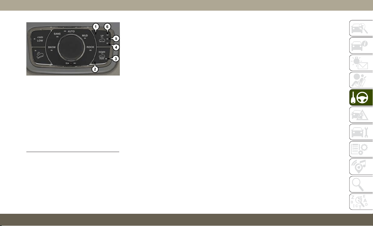
• Normal Ride Height (NRH) – This is the stan-
dard position of the suspension and is
meant for normal driving.
• Off-Road 1 (OR1) (Raises the vehicle approxi-
mately 1.1 inches (28 mm))
–Thisisthe
primary position for all off-road driving until
OR2 is needed. A smoother and more com-
fortable ride will result. Push the “UP” but-
ton once from the NRH position while the
vehicle speed is below 38 mph (61 km/h).
When in the OR1 position, if the vehicle
speed remains between 40 mph (64 km/h)
and 50 mph (80 km/h) for greater than
20 seconds or if the vehicle speed exceeds
50 mph (80 km/h), the vehicle will be auto-
matically lowered to NRH.
• Off-Road 2 (OR2) (Raises the vehicle approxi-
mately 2.2 inches (55 mm)) – This position is
intended for off-roading use only where
maximum ground clearance is required. To
enter OR2, push the “UP” button twice
from the NRH position or once from the
OR1 position while vehicle speed is below
20 mph (32 km/h). While in OR2, if the
vehicle speed exceeds 25 mph (40 km/h)
the vehicle height will be automatically
lowered to OR1.
• Aero Mode (Lowers the vehicle approximately
0.6 inches (15 mm)) – This position provides
improved aerodynamics by lowering the ve-
hicle. The vehicle will automatically enter
Aero Mode when the vehicle speed remains
between 52 mph (83 km/h) and 56 mph
(90 km/h) for greater than 20 seconds or if
the vehicle speed exceeds 56 mph
(90 km/h). The vehicle will return to NRH
from Aero Mode if the vehicle speed re-
mains between 20 mph (32 km/h) and
25 mph (40 km/h) for greater than 20 sec-
onds or if the vehicle speed falls below
20 mph (32 km/h). The vehicle will enter
Aero Mode, regardless of vehicle speed if
the vehicle is in “SPORT” mode.
• Entry/Exit Mode (Lowers the vehicle approxi-
mately 1.6 inches (40 mm) – This position
lowers the vehicle for easier passenger en-
try and exit as well as lowering the rear of
the vehicle for easier loading and unloading
of cargo. To enter Entry/Exit Mode, push the
“DOWN” button once from (NRH) while the
vehicle speed is below 25 mph (40 km/h).
Selec-Terrain Switch
1 — UP Button
2 — DOWN Button
3 — Entry/Exit Mode Indicator Lamp
(Customer Selectable)
4 — Normal Ride Height Indicator
Lamp (Customer Selectable)
5 — Off-Road 1 Indicator Lamp
(Customer Selectable)
6 — Off-Road 2 Indicator Lamp
(Customer Selectable)
165

Once the vehicle speed goes below 15 mph
(24 km/h) the vehicle height will begin to
lower. If the vehicle speed remains between
15 mph (24 km/h) and 25 mph (40 km/h)
for greater than 60 seconds, or the vehicle
speed exceeds 25 mph (40 km/h) the
Entry/Exit Mode change will be cancelled.
To exit Entry/Exit Mode, press the “Up”
button once while in Entry/Exit Mode or
drive the vehicle over 15 mph (24 km/h).
NOTE:
Automatic lowering of the vehicle into Entry/
Exit Mode can be enabled through the
Uconnect Touch-Screen Radio. If this feature
is enabled, the vehicle will only lower if the
gear selector is in "PARK", the terrain switch
is in "AUTO", the transfer-case is in "AUTO”
and the vehicle level should be either in
Normal or Aero Mode. The Vehicle will not
automatically lower if the air suspension level
is in Off Rd 2 or Off Rd 1. If the vehicle is
equipped with Intrusion Theft Module (ITM),
the lowering will be suppressed when the
ignition is switched OFF and the door is open
to prevent setting the alarm off.
T
he Selec-Terrain switch will automatically
change the vehicle to the proper height based
on the position of the Selec-Terrain switch. The
height can be changed from the default Selec-
Terrain setting by normal use of the air suspen-
sion buttons. Refer to “Selec-Terrain” in “Start-
ing And Operating” for further information.
The system requires that the engine be run-
ning for all changes. When lowering the ve-
hicle all of the doors, including the liftgate,
must be closed. If a door is opened at any
time while the vehicle is lowering the change
will not be completed until the open door(s)
is/are closed.
The Quadra-Lift air suspension system uses a
lifting and lowering pattern which keeps the
headlights from incorrectly shining into on-
coming traffic. When raising the vehicle, the
rear of the vehicle will move up first and then
the front. When lowering the vehicle, the
front will move down first and then the rear.
After the engine is turned off, it may be
noticed that the air suspension system oper-
ates briefly, this is normal. The system is
correcting the position of the vehicle to en-
sure a proper appearance.
To assist with changing a spare tire, the
Quadra-Lift air suspension system has a fea-
ture which allows the automatic leveling to
be disabled. Refer to “Uconnect Settings” in
“Multimedia” for further information.
For further information refer to “Driving Tips”
in “Starting And Operating” in the Owner’s
Manual.
NOTE:
If equipped with a touch screen radio all
enabling/disabling of air suspension features
must be done through the radio. Refer to
“Uconnect Settings” in “Multimedia” for fur-
ther information.
WARNING!
The air suspension system uses a high
pressure volume of air to operate the sys-
tem. To avoid personal injury or damage to
the system, see your authorized dealer for
service.
STARTING AND OPERATING
166

Air Suspension Modes
The Air Suspension system has multiple
modes to protect the system in unique situa-
tions:
Tire/Jack Mode
To assist with changing a spare tire, the air
suspension system has a feature which allows
the automatic leveling to be disabled. Refer
to “Uconnect Settings” in “Multimedia” for
further information.
NOTE:
This mode is intended to be enabled with
engine running.
Auto Entry/Exit Mode
T
o assist in entering and exiting the vehicle,
the air suspension system has a feature which
automatically lowers the vehicle to entry/exit
ride height. Refer to “Uconnect Settings” in
“Multimedia” for further information.
NOTE:
This mode is intended to be enabled with
engine running.
Transport Mode
To assist with flat bed towing, the air suspen-
sion system has a feature which will put the
vehicle into Entry/Exit height and disable the
automatic load leveling system. Refer to
“Uconnect Settings” in “Multimedia” for fur-
ther information.
NOTE:
This mode is intended to be enabled with
engine running.
Suspension Display Messages Mode
The “Suspension Display Messages” setting
allows you to only display suspension warn-
ings. Refer to “Uconnect Settings” in “Mul-
timedia” for further information.
NOTE:
This mode is intended to be enabled with
engine running.
Wheel Alignment Mode
Before performing a wheel alignment this mode
must be enabled. Refer to “Uconnect Settings”
in “Multimedia” for further information.
NOTE:
This mode is intended to be enabled with
engine running.
If equipped with a touch screen radio all
enabling/disabling of air suspension features
must be done through the radio. Refer to
“Uconnect Settings” in “Multimedia” for fur-
ther information.
Instrument Cluster Display Messages
When the appropriate conditions exist, a
message will appear in the instrument clus-
ter. Refer to “Instrument Cluster Display” in
“Getting To Know Your Instrument Panel” for
further information.
Operation
The indicator lamps 3 through 6 will illumi-
nate to show the current position of the ve-
hicle. Flashing indicator lamps will show a
position which the system is working to
achieve. When raising, if multiple indicator
lamps are flashing on the “UP” button, the
highest flashing indicator lamp is the posi-
tion the system is working to achieve. When
167

lowering, if multiple indicators are flashing
on the "DOWN" button the lowest solid indi-
cator lamp is the position the system is work-
ing to achieve.
Pushing the “UP” button once will move the
suspension one position higher from the cur-
rent position, assuming all conditions are
met (i.e. engine running, speed below thresh-
old, etc). The “UP” button can be pushed
multiple times, each push will raise the re-
quested level by one position up to a maxi-
mum position of OR2 or the highest position
allowed based on current conditions (i.e. ve-
hicle speed, etc).
Pushing the “DOWN” button once will move
the suspension one position lower from the
current level, assuming all conditions are met
(i.e. engine running, doors closed, speed be-
low threshold, etc). The “DOWN” button can
be pressed multiple times. Each push will
lower the requested level by one position
down to a minimum of Park Mode or the
lowest position allowed based on current con-
ditions (i.e. vehicle speed, etc.)
Automatic height changes will occur based
on vehicle speed and the current vehicle
height. The indicator lamps and instrument
cluster display messages will operate the
same for automatic changes and user re-
quested changes.
• Off-Road 2 (OR2) – Indicator lamps 4, 5,
and 6 will be illuminated when the vehicle
is in OR2.
• Off-Road 1 (OR1) – Indicator lamps 4 and
5 will be illuminated when the vehicle is in
OR1.
• Normal Ride Height (NRH) – Indicator
lamp 4 will be illuminated when the vehicle
is in this position.
• Entry/Exit Mode – Indicator lamp 3 will be
illuminated when the vehicle is in Entry/
Exit Mode. If Entry/Exit Mode is requested
while vehicle speed is between 15 mph
(24 km/h) and 25 mph (40 km/h), indicator
lamp 4 will remain on solid and indicator
lamp 3 will flash as the system waits for the
vehicle to reduce speed. If vehicle speed
is reduced to, and kept below, 15 mph
(24 km/h) indicator lamp 4 will turn off and
indicator lamp 3 will flash until Entry/Exit
Mode is achieved at which point indicator
lamp 3 will go solid. If during the height
change to Entry/Exit Mode, the vehicle
speed exceeds 15 mph (24 km/h), the
height change will be paused until the
vehicle speed either goes below 15 mph
(24 km/h) and the height change continues
to Entry/Exit Mode, or exceeds 25 mph
(40 km/h) and the vehicle height will return
to NRH. Entry/Exit Mode may be selected
while the vehicle is not moving provided
that the engine is still running and all doors
remain closed.
• Transport Mode - No indicator lamps will be
illuminated. Customer driving will disable
Transport Mode.
• Tire/Jack Mode - Indicator lamps 3 and
6 will be illuminated. Customer driving will
disable Tire/Jack Mode.
• Wheel Alignment Mode - Indicator lamps
3 and 4 will be illuminated. Customer driv-
ing will disable Wheel Alignment Mode.
STARTING AND OPERATING
168
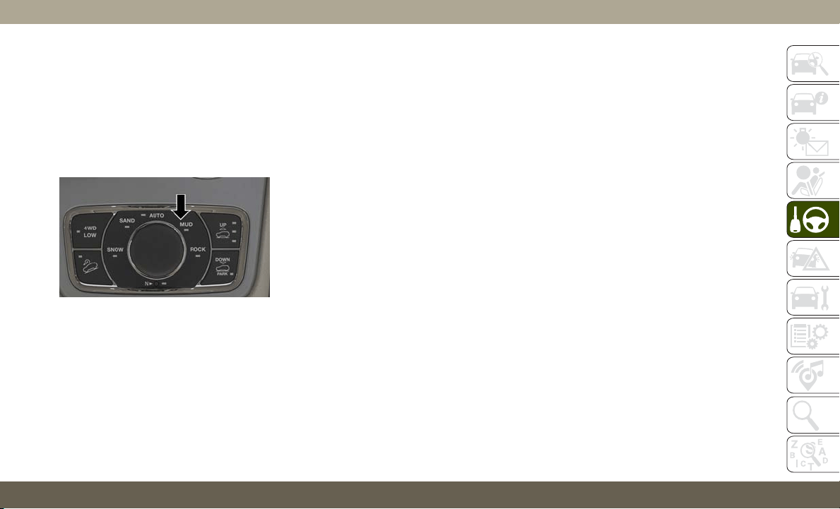
SELEC-TERRAIN —
IF EQUIPPED
Selec-Terrain Mode Selection
Selec-Terrain combines the capabilities of
the vehicle control systems, along with driver
input, to provide the best performance for all
terrains.
Selec-Terrain consists of the following posi-
tions:
• Snow – Tuning set for additional stability in
inclement weather. Use on and off road on
loose traction surfaces such as snow. When
in Snow mode (depending on certain oper-
ating conditions), the transmission may use
second gear (rather than first gear) during
launches, to minimize wheel slippage. If
equipped with air suspension, the default
ride height for Snow is Normal Ride Height
(NRH).
• Auto – Fully automatic full time four-wheel
drive operation can be used on and off road.
Balances traction with seamless steering
feel to provide improved handling and ac-
celeration over two-wheel drive vehicles. If
equipped with air suspension, the level will
change to Normal Ride Height (NRH).
• Sand – Off road calibration for use on low
traction surfaces such as sand or wet grass.
Driveline is maximized for traction. Some
binding may be felt on less forgiving sur-
faces. The electronic brake controls are set
to limit traction control management of
throttle and wheel spin. If equipped with air
suspension, the default ride height for
Sand is Normal Ride Height (NRH).
• Mud – Off road calibration for use on low
traction surfaces such as mud. Driveline is
maximized for traction. Some binding may
be felt on less forgiving surfaces. The elec-
tronic brake controls are set to limit traction
control management of throttle and wheel
spin. If equipped with air suspension, the
level will change to Off Road 1.
• Rock – Off road calibration only available
in 4WD Low range. The vehicle is raised (if
equipped with Air Suspension) for im-
proved ground clearance. Traction based
tuning with improved steer-ability for use
on high traction off-road surfaces. Use for
low speed obstacles such as large rocks,
deep ruts, etc. If equipped with air suspen-
sion, the vehicle level will change to Off-
Road 2. If the Selec-Terrain switch is in
ROCK mode, and the transfer case is
switched from 4WD Low to 4WD High, the
Selec-Terrain system will return to AUTO.
NOTE:
Activate the Hill Descent Control or Selec
Speed Control for steep downhill control. See
“Electronic Brake Control System” in this
section for further information.
Instrument Cluster Display Messages
When the appropriate conditions exist, a
message will appear in the instrument clus-
ter. Refer to “Instrument Cluster Display” in
“Getting To Know Your Instrument Panel” for
further information.
Selec-Terrain Switch
169
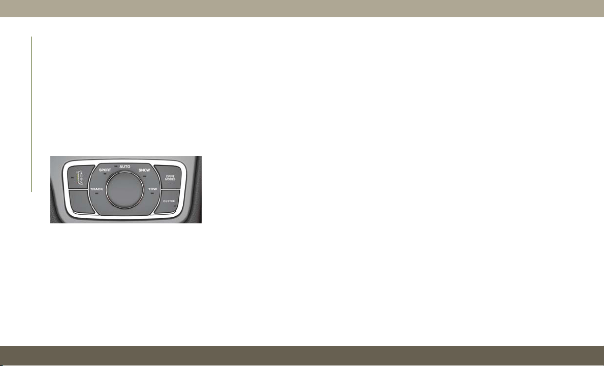
SELEC-TRACK —
IF EQUIPPED (SRT)
Description
Selec-Track combines the capabilities of the
vehicle control systems, along with driver
input, to provide the best performance for all
terrains.
Rotate the Selec-Track knob to select the
desired mode.
Refer to “SRT Drive Modes” in the “Multi-
media” section in your Owner’s Manual for
further information.
Selec-Track consists of the following posi-
tions:
• Sport – Dry weather, on-road calibration.
Performance based tuning that provides a
rear wheel drive feel but with improved
handling and acceleration over a two-wheel
drive vehicle. This feature will reset to
AUTO on an ignition cycle.
• Snow – Tuning set for additional stability in
inclement weather. Use on and off road on
loose traction surfaces such as snow. This
feature will reset to AUTO upon an ignition
cycle.
• Auto – Fully automatic full time four-wheel
drive operation can be used on and off road.
Balances traction with seamless steering
feel to provide improved handling and ac-
celeration over two-wheel drive vehicles.
• Track – Track road calibration for use on
high traction surfaces. Driveline is maxi-
mized for traction. Some binding may be
felt on less forgiving surfaces. This feature
will reset to AUTO on an ignition cycle.
• Tow – Use this mode for towing and hauling
heavy loads. Vehicle suspension will go to
sport mode. Trailer sway control is enabled
in the ESC system. This feature will reset to
AUTO upon an ignition cycle.
Custom
This mode allows the driver to create a cus-
tom vehicle configuration that is saved for
quick selection of favorite settings. The sys-
tem will return to AUTO mode when the
ignition switch is cycled from RUN to OFF to
RUN, if this mode is selected. While in Cus-
tom Mode the Stability, Transmission, Steer-
ing, Suspension, all-wheel drive set up, and
Paddle shifter settings may be configured
through the custom mode set-up.
NOTE:
Refer to “SRT Drive Modes” in the “Multime-
dia” section in your Owner’s Manual for fur-
ther information.
Selec-Track Switch
STARTING AND OPERATING
170

Active Damping System
This vehicle is equipped with an electronic
controlled damping system. This system re-
duces body roll and pitch in many driving
situations including cornering, acceleration
and braking. There are 3 modes:
• Street Mode (Available in terrain positions
AUTO, SNOW and CUSTOM.) — Used dur-
ing highway speeds where a touring sus-
pension feel is desired.
• Sport Mode (Available in terrain positions
AUTO, SPORT, CUSTOM and TOW.) — Pro-
vides a firm suspension for better handling.
• Track Mode (Available in terrain positions
AUTO, TRACK and CUSTOM.) — Provides
a full firm suspension for an aggressive
track experience.
Refer to “SRT Drive Modes” in the “Multime-
dia” section in your Owner’s Manual for fur-
ther information.
Launch Control— If Equipped
This vehicle is equipped with a Launch Con-
trol system that is designed to allow the driver
to achieve maximum vehicle acceleration in a
straight line. Launch Control is a form of
traction control that manages tire slip while
launching the vehicle. This feature is in-
tended for use during race events on a closed
course where consistent quarter mile and
zero to sixty times are desired. The system is
not intended to compensate for lack of driver
experience or familiarity with the race track.
Use of this feature in low traction (cold, wet,
gravel, etc.) conditions may results in excess
wheel slip outside this systems control result-
ing in an aborted launch.
Preconditions:
• Launch Control should not be used on pub-
lic roads. Always check track conditions
and the surrounding area.
• Launch Control is not available within the
first 500 miles (805 km) of engine break-
in.
• Launch Control should only be used when
the engine and transmission are at operat-
ing temperature.
• Launch Control is intended to be used on
dry, paved road surfaces only.
CAUTION!
Use on slippery or loose surfaces may
cause damage to vehicle components and
is not recommended.
Launch Control is only available when the
following procedure is followed:
NOTE:
Pushing the SRT button on the Select-Track
switch or pressing the “Apps” button on the
touchscreen are the two options to access
launch control features. Please refer to “SRT
Drive Modes” in “Multimedia” in your Own-
er’s Manual for further information.
1. Press the “Race Options” button on the
touchscreen or push the LAUNCH button
on the Select-Track switch.
171

2. Press the “Launch RPM Set-Up” button
on the touchscreen. This screen will allow
you to adjust your launch RPM’s for opti-
mum launch/traction.
3. Press the “Activate Launch Control” but-
ton on the touchscreen, follow instruc-
tions in the instrument cluster display.
• Make sure the vehicle is not moving.
• Put vehicle in first gear.
• Steering wheel must be pointing
straight.
• Vehicle must be on level ground.
• Apply brake pressure.
• While holding the brake, rapidly apply
and hold the accelerator pedal to wide
open throttle. The engine speed will
hold at the RPM that was set in the
“Launch RPM Set-up” screen.
NOTE:
Messages will appear in the instrument
cluster display to inform the driver if one
or more of the above conditions have not
been met.
4. When the above conditions have been
met, the instrument cluster display will
read “Release Brake”.
5. Keep the vehicle pointed straight.
Launch control will be active until the vehicle
reaches 62 mph (100 km/h), at which point
the Electronic Stability Control (ESC) system
will return to its current ESC mode.
Launch control will abort before launch
completion, display “Launch Aborted” in the
cluster under any the following conditions:
• The accelerator pedal is released during
launch.
• The ESC system detects that the vehicle is
no longer moving in a straight line.
• The “ESC OFF” button is pressed to change
the system to another mode.
NOTE:
After launch control has been aborted, ESC
will return to its current ESC mode.
CAUTION!
Do not attempt to shift when the drive
wheels are spinning and do not have
traction. Damage to the transmission may
occur.
Guidelines For Track Use
NOTE:
Because of the extreme conditions encoun-
tered during track use, any damage or wear
associated with track use may not be covered
by warranty.
• If your SRT vehicle is equipped with Drive
Modes they will alter the vehicle’s perfor-
mance in various driving situations. It is
recommended that your vehicle operates in
SPORT or TRACK modes during the track
event.
• Prior to each track event/day, verify all
fluids are at the correct levels. Refer to
“Fluid Capacities” in “Technical Specifica-
tions” for further information.
STARTING AND OPERATING
172

• Prior to each track event, verify the front
and rear brake pads have more than ½ pad
thickness remaining. If the brake pads re-
quire changing, please burnish prior to
track outing at full pace.
NOTE:
Use of DOT 4 brake fluid is suggested for
extended track usage due to increased ther-
mal capacity.
• At the conclusion of each track event, it is
recommended that a brake bleed procedure
is performed to maintain the pedal feel and
stopping capability of your Brembo High
Performance brake system.
• It is recommended that each track outing
should end with a minimum of one cool
down lap using minimal braking.
• If equipped with a removable lower front
fascia grille, it is recommended to remove it
for track use during warm/hot weather to
improve cooling airflow to critical pow-
ertrain and cooling system components.
• All SRT vehicles are track tested for
24 hours of endurance, however, it is rec-
ommended that suspension system, brake
system, prop shaft, and ½ shaft boots
should be checked for wear or damage after
every track event.
• Track usage results in increased operating
temperatures of the engine, transmission,
driveline and brake system. This may affect
noise vibrations and harshness (NVH)
countermeasures designed into your ve-
hicle. New components may need to be
installed to return the system to the original
NVH performance.
• Tire pressure:
–
40 psi (276 kpa) hot, recommend 32 psi
(221 kpa) front, 30 psi (207 kpa) rear
cold
NOTE:
It is recommended that you target 40 psi
(276 kpa) Hot Tire Pressure at the conclusion
of each track session. Starting at 32 psi
(221 kpa) Front & 30 psi (207 kpa) Rear Cold
and adjusting based on ambient & track con-
ditions is recommended. Tire pressure can be
monitored via the instrument cluster display
and can assist with adjustments.
Track burnishing your brakes:
To avoid “green lining fade” during track use,
the brake pads and rotors must have a ther-
mal burnish for factory installed components
or when new brake friction components are
installed:
1. Use one track session to burnish brakes by
driving at 75% speed. Brake at approxi-
mately 0.60-0.80g maximum without
ABS intervention.
2. Lap the track in this manner until you
start smelling the brakes. Continue for
another ½ lap at speed, then do a two lap
cool down with minimal brake applies.
Make sure the brakes are not smoking. If
they are, do another cool down lap.
173
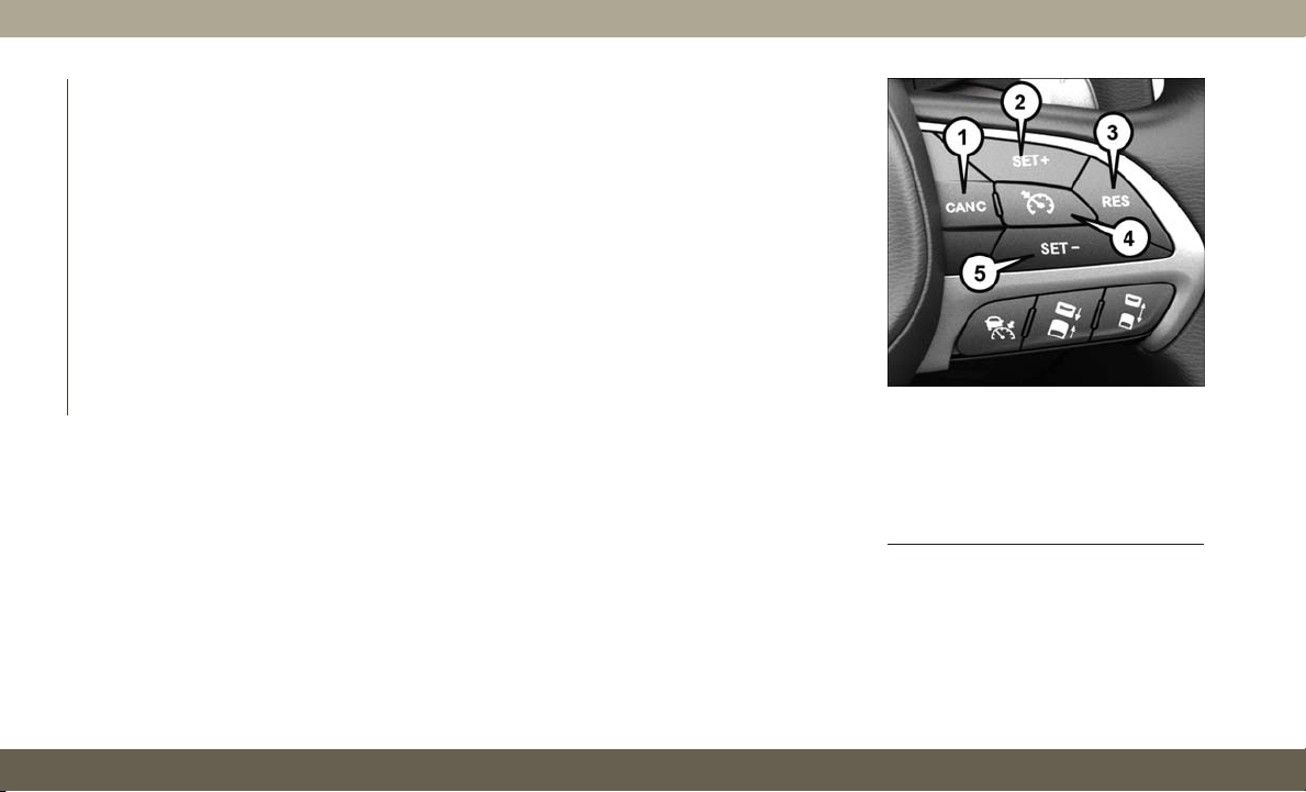
3. Do not continue for more than one full
burnishing lap after you start smelling the
brakes. Do not get them smoking heavily.
This will get them too hot and affect their
life negatively in future track use.
4. Allow vehicle to sit and cool in the pad-
dock for at least 30 min. If an infrared
thermal gun is available, allow rotors to
cool to 200°F (93.3°C) before going back
out.
5. There should be a thin, ash layer when
inspecting the pads installed in the cali-
per. Having the ash layer go more than
half the thickness of the pad material
indicates too aggressive of a burnish.
6. Sometimes, a second burnish session is
required. If the pads start smelling in the
next track session, reduce speed and
braking decel to burnish targets and fol-
low step 2-4.
7. New pads installed on old rotors still need
to be burnished. New rotors installed with
old pads should be burnished at the track
or street driven for 300 city miles to
develop an adequate lining transfer layer
on the rotor surface prior to track use.
8. Rotors that pulsate during track use
should be replaced. Resurfacing of the
rotors is not recommended, as it removes
mass from the rotor, reducing its thermal
capacity. Resurfacing also thins the rotor
cheek, making it less robust and increas-
ing the likelihood of pulsation in further
track use.
SPEED CONTROL —
IF EQUIPPED
When engaged, the Speed Control takes over
accelerator operations at speeds greater than
20 mph (32 km/h).
The Speed Control buttons are located on the
right side of the steering wheel.
Speed Control Switches
1 — CANC/Cancel
2 — SET (+)/Accel
3 — RES/Resume
4 — On/Off
5 — SET (-)/Decel
STARTING AND OPERATING
174
NOTE:
In order to ensure proper operation, the Speed
Control System has been designed to shut
down if multiple Speed Control functions are
operated at the same time. If this occurs, the
Speed Control System can be reactivated by
pushing the Speed Control on/off button and
resetting the desired vehicle set speed.
WARNING!
Speed Control can be dangerous where the
system cannot maintain a constant speed.
Your vehicle could go too fast for the con-
ditions, and you could lose control and
have an accident. Do not use Speed Con-
trol in heavy traffic or on roads that are
winding, icy, snow-covered or slippery.
To Activate
Push the on/off button to activate the Speed
Control. “CRUISE CONTROL READY” will
appear in the instrument cluster display to
indicate the Speed Control is on. To turn the
system off, push the on/off button a second
time. “CRUISE CONTROL OFF” will appear
in the instrument cluster display to indicate
the Speed Control is off. The system should
be turned off when not in use.
WARNING!
Leaving the Speed Control system on when
not in use is dangerous. You could acci-
dentally set the system or cause it to go
faster than you want. You could lose con-
trol and have an accident. Always leave the
system OFF when you are not using it.
To Set A Desired Speed
Turn the Speed Control on. When the vehicle
has reached the desired speed, push the SET
(+) or SET (-) button and release. Release the
accelerator and the vehicle will operate at the
selected speed. Once a speed has been set, a
message “CRUISE CONTROL SET TO MPH
(km/h)” will appear indicating what speed
was set. A cruise indicator lamp, along with
set speed will also appear and stay on in the
instrument cluster when the speed is set.
To Resume Speed
To resume a previously set speed, push the
RES button and release. Resume can be used
at any speed above 20 mph (32 km/h).
To Deactivate
A soft tap on the brake pedal, pushing the
CANC button, or normal brake pressure while
slowing the vehicle will deactivate the Speed
Control without erasing the set speed from
memory.
Pushing the on/off button or turning the igni-
tion switch OFF erases the set speed from
memory.
175
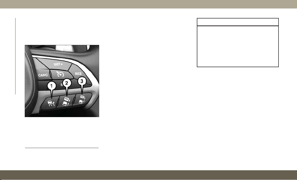
ADAPTIVE CRUISE
CONTROL (ACC) —
IF EQUIPPED
If your vehicle is equipped with Adaptive
Cruise Control, the controls operate exactly
the same as Speed Control with only a couple
of differences. With this option, you can set a
specified distance you would like to maintain
between you and the vehicle in front of you.
If the ACC sensor detects a vehicle ahead,
ACC will apply limited braking or acceleration
automatically to maintain a preset following
distance, while matching the speed of the
vehicle ahead.
If the sensor does not detect a vehicle ahead
of you, ACC will maintain a fixed set speed.
To Activate/Deactivate
Push and release the Adaptive Cruise Control
(ACC) on/off button. The ACC menu in the
instrument cluster displays “ACC Ready.”
To turn the system off, push and release the
Adaptive Cruise Control (ACC) on/off button
again. At this time, the system will turn off
and the instrument cluster displays “Adap-
tive Cruise Control (ACC) Off.”
WARNING!
Leaving the Adaptive Cruise Control (ACC)
system on when not in use is dangerous.
You could accidentally set the system or
cause it to go faster than you want. You
could lose control and have a collision.
Always leave the system off when you are
not using it.
To Set A Desired ACC Speed
When the vehicle reaches the speed desired,
push the SET (+) button or the SET (-) button
and release. The instrument cluster display
will display the set speed.
If the system is set when the vehicle speed is
below 20 mph (32 km/h), the set speed shall
be defaulted to 20 mph (32 km/h). If the
system is set when the vehicle speed is above
20 mph (32 km/h), the set speed shall be the
current speed of the vehicle.
Adaptive Cruise Switches
1 — Adaptive Cruise Control (ACC)
On/Off
2 — Distance Setting – Decrease
3 — Distance Setting – Increase
STARTING AND OPERATING
176
NOTE:
ACC cannot be set if there is a stationary
vehicle in front of your vehicle in close prox-
imity.
Remove your foot from the accelerator pedal.
If you do not, the vehicle may continue to
accelerate beyond the set speed. If this occurs:
• The message “DRIVER OVERRIDE” will
display in the instrument cluster display.
• The system will not be controlling the dis-
tance between your vehicle and the vehicle
ahead. The vehicle speed will only be de-
termined by the position of the accelerator
pedal.
To Resume
If there is a set speed in memory push the
RES (resume) button and then remove your
foot from the accelerator pedal. The instru-
ment cluster display will display the last set
speed.
NOTE:
• If your vehicle stays at standstill for longer
than two seconds, then the system will
cancel and the brake force will be ramped-
out. The driver will have to apply the brakes
to keep the vehicle at a standstill.
• ACC cannot be resumed if there is a station-
ary vehicle in-front of your vehicle in close
proximity.
WARNING!
The Resume function should only be used
if traffic and road conditions permit. Re-
suming a set speed that is too high or too
low for prevailing traffic and road condi-
tions could cause the vehicle to accelerate
or decelerate too sharply for safe opera-
tion. Failure to follow these warnings can
result in a collision and death or serious
personal injury.
To Vary The Speed Setting
To Increase Speed
While ACC is set, you can increase the set
speed by pushing the SET (+) button.
The driver's preferred units can be selected
through the instrument panel settings. Refer
to “Getting To Know Your Instrument Panel”
in the Owner’s Manual for more information.
The speed increment shown is dependant on
the chosen speed unit of U.S. (mph) or Metric
(km/h):
U.S. Speed (mph)
• Pushing the SET (+) button once will result
in a 1 mph increase in set speed. Each
subsequent tap of the button results in an
increase of 1 mph.
• If the button is continually pushed, the set
speed will continue to increase in 5 mph
increments until the button is released. The
increase in set speed is reflected in the
instrument cluster display.
177

Metric Speed (km/h)
• Pushing the SET (+) button once will result
in a 1 km/h increase in set speed. Each
subsequent tap of the button results in an
increase of 1 km/h.
• If the button is continually pushed, the set
speed will continue to increase in 10 km/h
increments until the button is released.
The increase in set speed is reflected in the
instrument cluster display.
To Decrease Speed
While ACC is set, the set speed can be de-
creased by pushing the SET (-) button.
The driver's preferred units can be selected
through the instrument panel settings. Refer
to “Getting To Know Your Instrument Panel”
in the Owner’s Manual for more information.
The speed increment shown is dependant on
the chosen speed unit of U.S. (mph) or Met-
ric (km/h):
U.S. Speed (mph)
• Pushing the SET (-) button once will result
in a 1 mph decrease in set speed. Each
subsequent tap of the button results in a
decrease of 1 mph.
• If the button is continually pushed, the set
speed will continue to decrease in 5 mph
decrements until the button is released.
The decrease in set speed is reflected in
the instrument cluster display.
Metric Speed (km/h)
• Pushing the SET (-) button once will result
in a 1 km/h decrease in set speed. Each
subsequent tap of the button results in a
decrease of 1 km/h.
• If the button is continually pushed, the set
speed will continue to decrease in 10 km/h
decrements until the button is released.
The decrease in set speed is reflected in
the instrument cluster display.
NOTE:
• When you override and push the SET (+)
button or SET (-) buttons, the new set
speed will be the current speed of the
vehicle.
• When you use the SET (-) button to decel-
erate, if the engine’s braking power does
not slow the vehicle sufficiently to reach
the set speed, the brake system will auto-
matically slow the vehicle.
• The ACC system applies the brake down to
a full stop when following a target vehicle.
If an ACC host vehicle follows a target
vehicle to a standstill, the host vehicle will
release the vehicle brakes two seconds af-
ter coming to a full stop.
• The ACC system maintains set speed when
driving up hill and down hill. However, a
slight speed change on moderate hills
is normal. In addition, downshifting may
occur while climbing uphill or descending
downhill. This is normal operation and nec-
essary to maintain set speed. When driving
up hill and down hill, the ACC system will
cancel if the braking temperature exceeds
normal range (overheated).
Setting The Following Distance In ACC
The specified following distance for ACC can
be set by varying the distance setting be-
tween four bars (longest), three bars (long),
two bars (medium) and one bar (short). Using
this distance setting and the vehicle speed,
ACC calculates and sets the distance to the
vehicle ahead. This distance setting displays
in the instrument cluster display.
STARTING AND OPERATING
178

To increase the distance setting, push the Dis-
tance Setting — Increase button and release.
Each time the button is pushed, the distance
setting increases by one bar (longer).
To decrease the distance setting, push the
Distance Setting — Decrease button and re-
lease. Each time the button is pushed, the
distance setting decreases by one bar (shorter).
General Information
The following regulatory statement applies to
all Radio Frequency (RF) devices equipped in
this vehicle:
This device complies with Part 15 of the FCC
Rules and with Industry Canada license-
exempt RSS standard(s). Operation is sub-
ject to the following two conditions:
1. This device may not cause harmful inter-
ference.
2. This device must accept any interference
received, including interference that may
cause undesired operation.
NOTE:
Changes or modifications not expressly ap-
proved by the party responsible for compli-
ance could void the user’s authority to oper-
ate the equipment.
PARKSENSE REAR PARK
ASSIST — IF EQUIPPED
The ParkSense Rear Park Assist system pro-
vides visual and audible indications of the
distance between the rear fascia and a de-
tected obstacle when backing up, e.g. during
a parking maneuver. If your vehicle is
equipped with an automatic transmission,
the vehicle brakes may be automatically ap-
plied and released when performing a reverse
parking maneuver if the system detects a
possible collision with an obstacle.
Refer to “ParkSense System Usage Precau-
tions” in this section for limitations of this
system and recommendations.
ParkSense will retain the last system state
(enabled or disabled) from the last ignition
cycle when the ignition is changed to the
ON/RUN position.
ParkSense Sensors
The four ParkSense sensors, located in the
rear fascia/bumper, monitor the area behind
the vehicle that is within the sensors’ field of
view. The sensors can detect obstacles from
approximately 12 inches (30 cm) up to
79 inches (200 cm) from the rear fascia/
bumper in the horizontal direction, depend-
ing on the location, type and orientation of
the obstacle.
ParkSense Warning Display
The ParkSense Warning screen will only be
displayed if Sound and Display is selected
from the Customer - Programmable Features
section of the Uconnect System.
Refer to "Uconnect Settings” in “Multime-
dia” in your Owner’s Manual for further infor-
mation.
The ParkSense Warning screen is located
within the instrument cluster display. It pro-
vides visual warnings to indicate the distance
between the rear fascia/bumper and the de-
tected obstacle.
179

Refer to “Instrument Cluster Display” in
“Getting To Know Your Instrument Panel” in
your Owner’s Manual for further information.
Enabling And Disabling ParkSense
ParkSense can be enabled and disabled with
the ParkSense switch.
When the ParkSense switch is
pushed to disable the system, the
instrument cluster will display the
“PARKSENSE OFF” message for
approximately five seconds. When the gear
selector is moved to REVERSE and the sys-
tem is disabled, the instrument cluster dis-
play will display the “PARKSENSE OFF”
message for as long as the vehicle is in
REVERSE.
Refer to “Instrument Cluster Display” in
“Getting To Know Your Instrument Panel” in
your Owner’s Manual for further information.
The ParkSense switch LED will be on when
ParkSense is disabled or requires service.
The ParkSense switch LED will be off when
the system is enabled. If the ParkSense
switch is pushed, and the system requires
service, the ParkSense switch LED will blink
momentarily, and then the LED will be on.
ParkSense System Usage Precautions
NOTE:
• Ensure that the rear bumper is free of snow,
ice, mud, dirt and debris to keep the
ParkSense system operating properly.
• Jackhammers, large trucks, and other vi-
brations could affect the performance of
ParkSense.
• When you turn ParkSense off, the instru-
ment cluster will display “PARKSENSE
OFF.” Furthermore, once you turn
ParkSense off, it remains off until you turn
it on again, even if you cycle the ignition.
• When you move the gear selector to the
REVERSE position and ParkSense is
turned off, the instrument cluster display
will display “PARKSENSE OFF” message
for as long as the vehicle is in REVERSE.
• ParkSense, when on, will reduce the vol-
ume of the radio when it is sounding a tone.
• Clean the ParkSense sensors regularly, tak-
ing care not to scratch or damage them.
The sensors must not be covered with ice,
snow, slush, mud, dirt or debris. Failure to
do so can result in the system not working
properly. The ParkSense system might not
detect an obstacle behind the fascia/
bumper, or it could provide a false indica-
tion that an obstacle is behind the fascia/
bumper.
• Use the ParkSense switch to turn the
ParkSense system off if objects such as
bicycle carriers, trailer hitches, etc. are
placed within 12 inches (30 cm) from the
rear fascia/bumper. Failure to do so can
result in the system misinterpreting a close
object as a sensor problem, causing the
“PARKSENSE UNAVAILABLE SERVICE
REQUIRED” message to be displayed in
the instrument cluster display.
• ParkSense should be disabled when the
liftgate is in the open position and the
vehicle is in REVERSE. An open liftgate
could provide a false indication that an
obstacle is behind the vehicle.
STARTING AND OPERATING
180
WARNING!
• Drivers must be careful when backing up
even when using ParkSense. Always
check carefully behind your vehicle, look
behind you, and be sure to check for
pedestrians, animals, other vehicles, ob-
structions, and blind spots before back-
ing up. You are responsible for safety
and must continue to pay attention to
your surroundings. Failure to do so can
result in serious injury or death.
• Before using ParkSense, it is strongly
recommended that the ball mount and
hitch ball assembly is disconnected
from the vehicle when the vehicle is not
used for towing. Failure to do so can
result in injury or damage to vehicles or
obstacles because the hitch ball will be
much closer to the obstacle than the rear
fascia when the loudspeaker sounds the
continuous tone. Also, the sensors could
detect the ball mount and hitch ball
assembly, depending on its size and
shape, giving a false indication that an
obstacle is behind the vehicle.
CAUTION!
• ParkSense is only a parking aid and it is
unable to recognize every obstacle, in-
cluding small obstacles. Parking curbs
might be temporarily detected or not
detected at all. Obstacles located above
or below the sensors will not be detected
when they are in close proximity.
• The vehicle must be driven slowly when
using ParkSense in order to be able to
stop in time when an obstacle is de-
tected. It is recommended that the
driver looks over his/her shoulder when
using ParkSense.
PARKSENSE FRONT AND
REAR PARK ASSIST —
IF EQUIPPED
The ParkSense Park Assist system provides
visual and audible indications of the distance
between the rear and/or front fascia and a
detected obstacle when backing up or moving
forward, e.g. during a parking maneuver.
If your vehicle is equipped with an automatic
transmission, the vehicle brakes may be au-
tomatically applied and released when per-
forming a reverse parking maneuver if the
system detects a possible collision with an
obstacle.
Refer to “ParkSense System Usage Precau-
tions” in “Starting And Operating” in your
Owner’s Manual for limitations of this system
and recommendations.
ParkSense will retain the last system state
(enabled or disabled) from the last ignition
cycle when the ignition is changed to the
ON/RUN position.
ParkSense Sensors
The four ParkSense sensors (or six, if equipped
with Active Park Assist), located in the rear
fascia/bumper, monitor the area behind the
vehicle that is within the sensors’ field of view.
The sensors can detect obstacles from approxi-
mately 12 inches (30 cm) up to 79 inches
(200 cm) from the rear fascia/bumper in the
horizontal direction, depending on the loca-
tion, type and orientation of the obstacle.
181

The six ParkSense sensors, located in the
front fascia/bumper, monitor the area in front
of the vehicle that is within the sensors’ field
of view. The sensors can detect obstacles
from approximately 12 inches (30 cm) up to
47 inches (120 cm) from the front fascia/
bumper in the horizontal direction, depend-
ing on the location, type and orientation of
the obstacle.
When an object is detected within 79 inches
(200 cm) behind the rear bumper while the
vehicle is in REVERSE, a warning will appear
in the instrument cluster display. In addition
a chime will sound (when Sound and Display
is selected from the Customer Programmable
Features section of the Uconnect System
screen). As the vehicle moves closer to the
object, the chime rate will change from single
1/2 second tone (for rear only), to slow (for
rear only), to fast, to continuous.
Enabling And Disabling ParkSense
ParkSense can be enabled and disabled with
the ParkSense switch.
When the ParkSense switch is
pushed to disable the system, the
instrument cluster will display the
“PARKSENSE OFF” message for
approximately five seconds. When the gear
selector is moved to REVERSE and the sys-
tem is disabled, the instrument cluster dis-
play will display the “PARKSENSE OFF”
message for as long as the vehicle is in
REVERSE.
Refer to “Instrument Cluster Display” in
“Getting To Know Your Instrument Panel” in
your Owner’s Manual for further information.
NOTE:
When ParkSense is disabled and the gear
selector is moved to the DRIVE position, no
warning message will be displayed.
The ParkSense switch LED will be on when
ParkSense is disabled or requires service.
The ParkSense switch LED will be off when
the system is enabled. If the ParkSense
switch is pushed, and the system requires
service, the ParkSense switch LED will blink
momentarily, and then the LED will be on.
PARKSENSE ACTIVE PARK
ASSIST SYSTEM — IF
EQUIPPED
The ParkSense Active Park Assist system is
intended to assist the driver during parallel
and perpendicular parking maneuvers by
identifying a proper parking space, providing
audible/visual instructions, and controlling
the steering wheel. The ParkSense Active
Park Assist system is defined as “semi-
automatic” since the driver maintains control
of the accelerator, gear selector and brakes.
Depending on the driver's parking maneuver
selection, the ParkSense Active Park Assist
system is capable of maneuvering a vehicle
into a parallel or a perpendicular parking
space on either side (i.e., driver side or pas-
senger side).
STARTING AND OPERATING
182
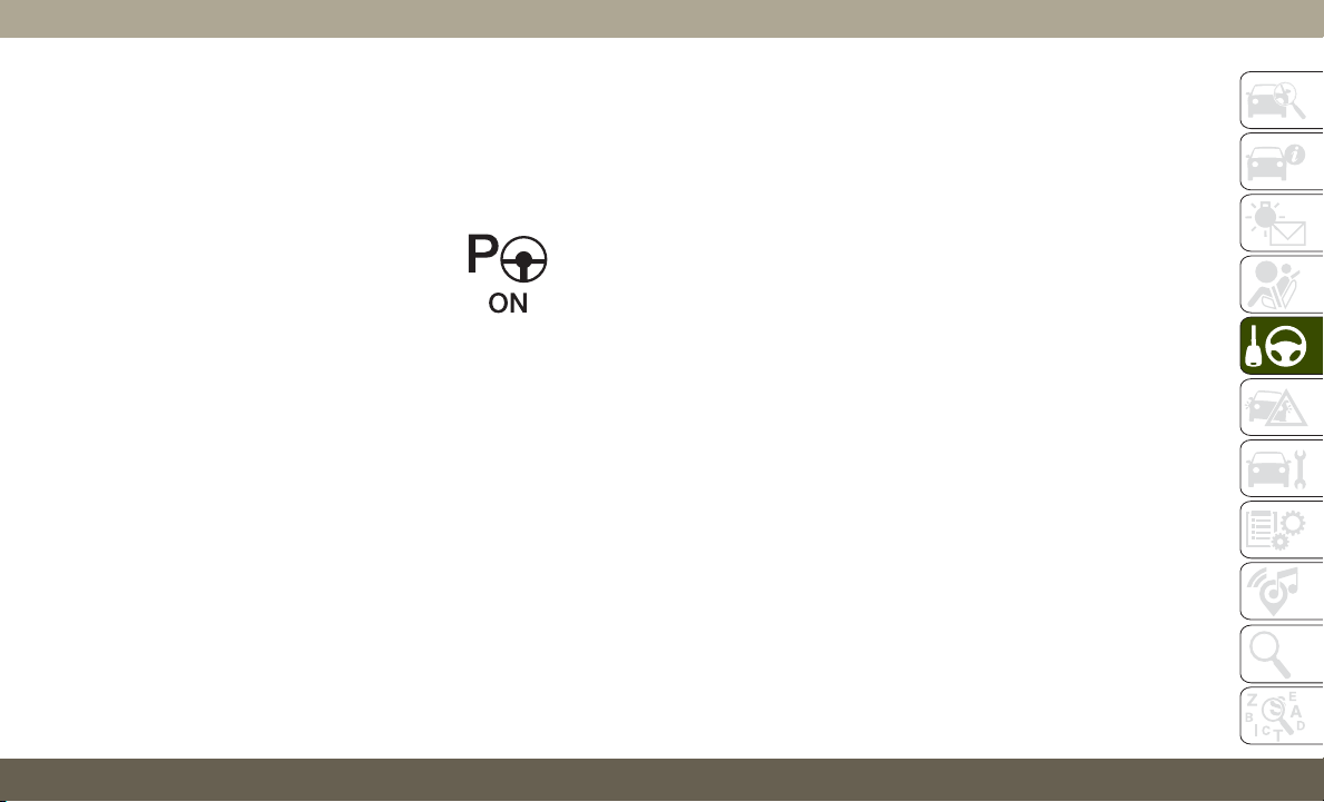
NOTE:
•
The driver is always responsible for control-
ling the vehicle, responsible for any surround-
ing objects, and must intervene as required.
• The system is provided to assist the driver
and not to substitute the driver.
• During a semi-automatic maneuver, if the
driver touches the steering wheel after be-
ing instructed to remove their hands from
the steering wheel, the system will cancel,
and the driver will be required to manually
complete the parking maneuver.
• The system may not work in all conditions
(e.g. environmental conditions such as
heavy rain, snow, etc., or if searching for a
parking space that has surfaces that will
absorb the ultrasonic sensor waves).
• New vehicles from the dealership must
have at least 30 miles (48 km) accumu-
lated before the ParkSense Active Park
Assist system is fully calibrated and per-
forms accurately. This is due to the sys-
tem’s dynamic vehicle calibration to im-
prove the performance of the feature.
The system will also continuously perform
the dynamic vehicle calibration to account
for differences such as over or under in-
flated tires and new tires.
Enabling And Disabling The ParkSense
Active Park Assist System
The ParkSense Active Park As-
sist system can be enabled and
disabled with the ParkSense Ac-
tive Park Assist switch, located
on the switch panel below the
Uconnect display.
To enable the ParkSense Active Park Assist
system, push the ParkSense Active Park As-
sist switch once (LED turns on).
To disable the ParkSense Active Park Assist
system, push the ParkSense Active Park As-
sist switch again (LED turns off).
When the ParkSense Active Park Assist system
is enabled the “Active ParkSense Searching -
Push OK to Switch to Perpendicular” message
will appear in the instrument cluster display.
You may switch to perpendicular parking if you
desire. Push the OK button on the left side
steering wheel switch to change your parking
space setting. You may switch back to parallel
parking if you desire.
When searching for a parking space, use the
turn signal indicator to select which side of
the vehicle you want to perform the parking
maneuver.
NOTE:
If the turn signal is not activated, the
ParkSense Active Park Assist system will au-
tomatically search for a parking space on the
passenger's side of the vehicle.
Refer to your Owner's Manual for further
information.
LANESENSE — IF EQUIPPED
LaneSense Operation
The LaneSense system is operational at
speeds above 37 mph (60 km/h) and below
112 mph (180 km/h). The LaneSense system
uses a forward looking camera to detect lane
markings and measure vehicle position
within the lane boundaries.
183
When both lane markings are detected and
the driver unintentionally drifts out of the
lane (no turn signal applied), the LaneSense
system provides a haptic warning in the form
of torque applied to the steering wheel to
prompt the driver to remain within the lane
boundaries. If the driver continues to unin-
tentionally drift out of the lane, the Lane-
Sense system provides a visual warning
through the instrument cluster display to
prompt the driver to remain within the lane
boundaries.
The driver may manually override the haptic
warning by applying torque into the steering
wheel at any time.
When only a single lane marking is detected
and the driver unintentionally drifts across
the lane marking (no turn signal applied), the
LaneSense system provides visual warnings
through the instrument cluster display to
prompt the driver to remain within the lane.
When only a single lane marking is detected,
a haptic (torque) warning will not be pro-
vided.
NOTE:
When operating conditions have been met,
the LaneSense system will monitor if the
driver’s hands are on the steering wheel and
provides an audible warning to the driver
when the driver’s hands are not detected on
the steering wheel. The system will cancel if
the driver does not return their hands to the
wheel.
Turning LaneSense On Or Off
The default status of LaneSense is off. The
LED in LaneSense button will be illuminated
while the system is deactivated.
The LaneSense button is located
on the switch panel below the
Uconnect display.
To turn the LaneSense system
on, push the LaneSense button (LED turns
off). A “LaneSense On” message is shown in
the instrument cluster display.
To turn the LaneSense system off, push the
LaneSense button once (LED turns on).
NOTE:
The LaneSense system will retain the last
system state on or off from the last ignition
cycle when the ignition is changed to the
ON/RUN position.
LaneSense Warning Message
The LaneSense system will indicate the cur-
rent lane drift condition through the instru-
ment cluster display.
Premium Instrument Cluster Display
When the LaneSense system is on; the lane
lines are gray when both of the lane bound-
aries have not been detected and the Lane-
Sense telltale
is solid white.
Left Lane Departure — Only Left Lane Detected
• When the LaneSense system is on, the
LaneSense telltale
is solid white when
only the left lane marking has been de-
tected and the system is ready to provide
visual warnings in the instrument cluster
display if an unintentional lane departure
occurs.
STARTING AND OPERATING
184
• When the LaneSense system senses the
lane has been approached and is in a lane
departure situation, the left thick lane line
flashes yellow (on/off), the left thin line
remains solid yellow and the LaneSense
telltale
changes from solid white to
flashing yellow.
NOTE:
The LaneSense system operates with the
similar behavior for a right lane departure
when only the right lane marking has been
detected.
Left Lane Departure — Both Lanes Detected
• When the LaneSense system is on, the lane
lines turn from gray to white to indicate that
both of the lane markings have been de-
tected. The LaneSense telltale
is solid
green when both lane markings have been
detected and the system is on to provide
visual warnings in the instrument cluster
display and a torque warning in the steering
wheel if an unintentional lane departure
occurs.
• When the LaneSense system senses a lane
drift situation, the left thick lane line and
left thin line turn solid yellow. The Lane-
Sense telltale
changes from solid green
to solid yellow. At this time torque is ap-
plied to the steering wheel in the opposite
direction of the lane boundary.
For example: If approaching the left side of
the lane the steering wheel will turn to the
right.
• When the LaneSense system senses the
lane has been approached and is in a lane
departure situation, the left thick lane line
flashes yellow (on/off) and the left thin line
remains solid yellow. The LaneSense tell-
tale
changes from solid yellow to flash-
ing yellow. At this time torque is applied to
the steering wheel in the opposite direction
of the lane boundary.
For example: If approaching the left side of
the lane the steering wheel will turn to the
right.
NOTE:
The LaneSense system operates with the
similar behavior for a right lane departure.
Changing LaneSense Status
The LaneSense system has settings to adjust
the intensity of the torque warning and the
warning zone sensitivity (early/late) that you
can configure through the Uconnect system
screen. Refer to “Uconnect Settings” in
“Multimedia” in your Owner’s Manual for
further information.
NOTE:
• When enabled the system operates above
37 mph (60 km/h) and below 112 mph
(180 km/h).
• Use of the turn signal suppresses the warn-
ings.
• The system will not apply torque to the
steering wheel whenever a safety system
engages (anti-lock brakes, traction control
system, electronic stability control, forward
collision warning, etc.).
185

PARKVIEW REAR BACK UP
CAMERA
The ParkView Rear Back Up Camera allows
you to see an on-screen image of the rear
surroundings of your vehicle whenever the
gear selector is put into REVERSE. The im-
age will be displayed on the Navigation/
Multimedia radio display screen along with a
caution note to “check entire surroundings”
across the top of the screen. After five sec-
onds this note will disappear. The ParkView
camera is located on the rear of the vehicle
above the rear license plate.
When the vehicle is shifted out of REVERSE
(with camera delay turned off), the rear cam-
era mode is exited and the navigation or
audio screen appears again.
Manual Activation Of The Rear View Camera
1. Press the “Controls” button located on
the bottom of the Uconnect display.
2. Press the “Backup Camera” button to
turn the Rear View Camera system on.
NOTE:
The ParkView Rear Back Up Camera has
programmable modes of operation that may
be selected through the Uconnect System.
Refer to “Uconnect Settings” in “Multimedia”
in your Owner’s Manual for further information.
When the vehicle is shifted out of REVERSE
(with camera delay turned off), the rear cam-
era mode is exited and the previous screen
appears again. When the vehicle is shifted
out of REVERSE (with camera delay turned
on), the camera image will continue to be
displayed for up to ten seconds after shifting
out of REVERSE unless the vehicle speed
exceeds 8 mph (13 km/h), the vehicle is
shifted into PARK, the vehicle’s ignition is
cycled to the OFF position, or the user
presses image defeat [X] to exit out of the
camera video display.
When enabled, active guide lines are overlaid
on the image to illustrate the width of the
vehicle and its projected backup path based
on the steering wheel position. A dashed
center line overlay indicates the center of the
vehicle to assist with parking or aligning to a
hitch/receiver. Different colored zones indi-
cate the distance to the rear of the vehicle.
The following table shows the approximate
distances for each zone:
Zone
Distance To The Rear Of
The Vehicle
Red 0-1ft(0-30cm)
Yellow
1 ft - 6.5 ft
(30cm-2m)
Green
6.5 ft or greater
(2 m or greater)
WARNING!
Drivers must be careful when backing up
even when using the ParkView Rear Back
Up Camera. Always check carefully behind
your vehicle, and be sure to check for
pedestrians, animals, other vehicles, ob-
structions, or blind spots before backing
up. You are responsible for the safety of
your surroundings and must continue to
pay attention while backing up. Failure to
do so can result in serious injury or death.
STARTING AND OPERATING
186
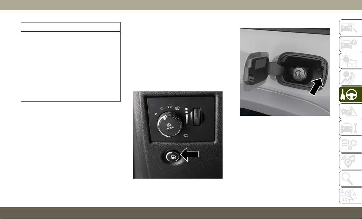
CAUTION!
•
To avoid vehicle damage, ParkView should
only be used as a parking aid. The
ParkView camera is unable to view every
obstacle or object in your drive path.
• To avoid vehicle damage, the vehicle
must be driven slowly when using
ParkView to be able to stop in time when
an obstacle is seen. It is recommended
that the driver look frequently over his/
her shoulder when using ParkView.
NOTE:
If snow, ice, mud, or any foreign substance
builds up on the camera lens, clean the lens,
rinse with water, and dry with a soft cloth. Do
not cover the lens.
Rear Camera — Viewing At Speed
When the vehicle is in park, neutral or drive,
the Rear View Camera can be activated with
the “Rear View Camera” button in the Con-
trols menu. This feature allows the customer
to monitor the area directly behind the ve-
hicle (or trailer, if equipped) for up to ten
seconds while at speed. If the vehicle speed
remains below 8 mph (13 km/h), the Rear
View Camera image will be displayed con-
tinuously until deactivated via the “X” button
on the touchscreen.
REFUELING THE VEHICLE —
GASOLINE ENGINE
1. Push the fuel filler door release switch
(located under the headlamp switch).
2. Open the fuel filler door.
NOTE:
In certain cold conditions, ice may prevent
the fuel door from opening. If this occurs,
lightly push on the fuel door to break the ice
buildup and re-release the fuel door using the
inside release button. Do not pry on the door.
3. There is no fuel filler cap. Two flapper
doors inside the pipe seals the system.
Fuel Filler Door Release Switch
Fuel Filler Door Latch
187
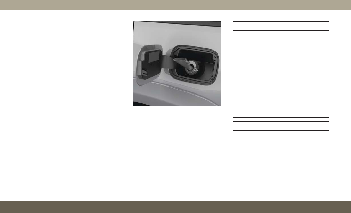
4. Insert the fuel nozzle fully into the filler
pipe, the nozzle opens and holds the flap-
per doors while refueling.
5. Fill the vehicle with fuel, when the fuel
nozzle “clicks” or shuts off the fuel tank is
full.
6. Wait five seconds before removing the
fuel nozzle to allow fuel to drain from
nozzle.
7. Remove the fuel nozzle and close the fuel
door.
Emergency Gas Can Refueling
Most gas cans will not open the flapper doors.
A funnel is provided to open the flapper doors
to allow emergency refueling with a gas can.
1. Retrieve funnel from the spare tire storage
area.
2. Insert funnel into same filler pipe opening
as the fuel nozzle.
3. Ensure funnel is inserted fully to hold
flapper doors open.
4. Pour fuel into funnel opening.
5. Remove funnel from filler pipe, clean off
prior to putting back in the spare tire
storage area.
WARNING!
• Never have any smoking materials lit in
or near the vehicle when the fuel door is
open or the tank is being filled.
• Never add fuel when the engine is run-
ning. This is in violation of most state
and federal fire regulations and may
cause the “Malfunction Indicator Light”
to turn on.
• A fire may result if fuel is pumped into a
portable container that is inside of a
vehicle. You could be burned. Always
place fuel containers on the ground
while filling.
CAUTION!
To avoid fuel spillage and overfilling, do
not “top off” the fuel tank after filling.
Fuel Filler
STARTING AND OPERATING
188
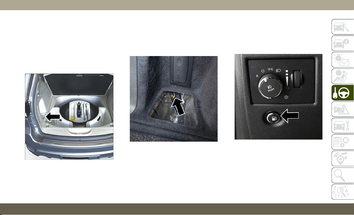
Emergency Fuel Filler Door Release
If you are unable to open the fuel filler door,
use the fuel filler door emergency release.
1. Open the liftgate.
2. Push the inboard edge of the left storage
bin to the center, this will pop up the
outboard edge.
3. Grab popped up outboard edge with other
hand to disengage snaps.
4. Remove the storage bin.
5. Pull the release cable to open the fuel
door, push the release cable back to the
home position to re-seat the fuel door
latch to the closed position.
NOTE:
If the fuel door does not latch after the
manual release cable has been activated, the
actuator latch should be manually returned to
the closed position.
REFUELING THE VEHICLE —
DIESEL ENGINE
1. Press the fuel filler door release switch
(located under the headlamp switch).
2. Open the fuel filler door.
Storage Bin Location
Release Cable
Fuel Filler Door Release Switch
189
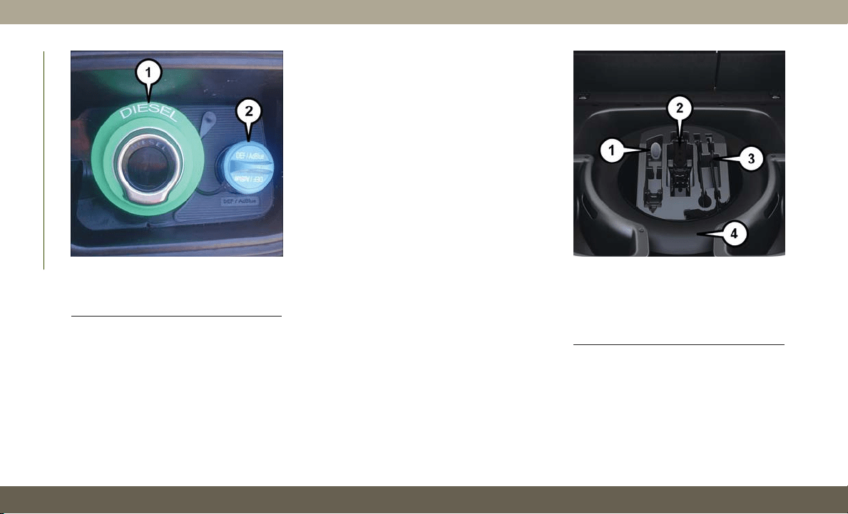
NOTE:
There is no fuel filler cap. A flapper door
inside the filler pipe seals the system.
3. Insert the fuel nozzle fully into the filler
pipe – the nozzle opens and holds the
flapper door while refueling.
4. Fill the vehicle with fuel – when the fuel
nozzle “clicks” or shuts off the fuel tank is
full.
5. Wait five seconds before removing the
nozzle to allow fuel to drain from the
nozzle.
6. Remove the fuel nozzle and close the fuel
door.
Emergency Fuel Can Refueling
Most fuel cans will not open the flapper door.
A funnel is provided to open the flapper door
to allow emergency refueling with a fuel can.
1. Retrieve funnel from the spare tire kit.
2. Insert funnel into same filler pipe opening
as the fuel nozzle.
Fuel and Diesel Exhaust Fluid Fill Location
1 — Fuel Fill Location
2 — Diesel Exhaust Fluid Fill Location
Fuel Fill Funnel/Spare Tire/Jack And Tools
1 — Cap-Less Fuel Fill Funnel
2 — Jack
3 — Tire Changing Tools
4 — Spare Tire
STARTING AND OPERATING
190

NOTE:
Ensure funnel is inserted fully to hold
flapper door open.
3. Pour fuel into funnel opening.
4. Remove funnel from filler pipe, clean off
prior to putting back in the spare tire kit.
WARNING!
• Never have any smoking materials lit in
or near the vehicle when the fuel door is
open or the tank is being filled.
• Never add fuel when the engine is run-
ning. This is in violation of most state
and federal fire regulations and may
cause the “Malfunction Indicator Light”
to turn on.
• A fire may result if fuel is pumped into a
portable container that is inside of a
vehicle. You could be burned. Always
place fuel containers on the ground
while filling.
CAUTION!
To avoid fuel spillage and overfilling, do
not “top off” the fuel tank after filling.
Avoid Using Contaminated Fuel
Fuel that is contaminated by water or dirt can
cause severe damage to the engine fuel sys-
tem. Proper maintenance of the engine fuel
filter and fuel tank is essential. Refer to
“Dealer Service” in “Servicing And Mainte-
nance” in your Diesel Supplement for further
information, which can be found with your
online Owner’s Information.
Bulk Fuel Storage — Diesel Fuel
If you store quantities of fuel, good mainte-
nance of the stored fuel is also essential. Fuel
contaminated with water will promote the
growth of “microbes.” These microbes form
“slime” that will clog the fuel filtration sys-
tem and lines. Drain condensation from the
supply tank and change the line filter on a
regular basis.
NOTE:
When a diesel engine is allowed to run out of
fuel, air is pulled into the fuel system.
Emergency Fuel Fill Location
191

If the vehicle will not start, refer to “Dealer
Service / Priming If The Engine Has Run Out
Of Fuel” in “Servicing And Maintenance” in
your Diesel Supplement for further informa-
tion, which can be found with your online
Owner’s Information.
WARNING!
Do not open the high pressure fuel system
with the engine running. Engine operation
causes high fuel pressure. High pressure
fuel spray can cause serious injury or
death.
Diesel Exhaust Fluid
Y
our vehicle is equipped with a Selective Cata-
lytic Reduction system to meet the very strin-
gent diesel emissions standards required by
the Environmental Protection Agency.
The purpose of the SCR system is to reduce
levels of NOx (oxides of nitrogen emitted from
engines) that are harmful to our health and
the environment to a near-zero level. A small
quantity of Diesel Exhaust Fluid (DEF) is
injected into the exhaust upstream of a cata-
lyst where, when vaporized, it converts smog-
forming nitrogen oxides (NOx) into harmless
nitrogen (N2) and water vapor (H2O), two
natural components of the air we breathe.
You can operate with the comfort that your
vehicle is contributing to a cleaner, healthier
world environment for this and generations to
come.
System Overview
This vehicle is equipped with a Diesel Ex-
haust Fluid (DEF) injection system and a
Selective Catalytic Reduction (SCR) catalyst
to meet the emission requirements.
The DEF injection system consists of the
following components:
• DEF tank
• DEF pump
• DEF injector
• Electronically-heated DEF Lines
• NOx sensors
• Temperature sensors
• SCR catalyst
The DEF injection system and SCR catalyst
enable the achievement of diesel emissions
requirements; while maintaining outstanding
fuel economy, drivability, torque and power
ratings.
Refer to “Instrument Cluster Display” in
“Getting To Know Your Instrument Panel” for
system messages and warnings.
NOTE:
• Your vehicle is equipped with a DEF injec-
tion system. You may occasionally hear an
audible clicking noise from under the ve-
hicle at a stop. This is normal operation.
• The DEF pump will run for a period of time
after engine shutdown to purge the DEF
system. This is normal operation and may
be audible from the rear of the vehicle.
STARTING AND OPERATING
192
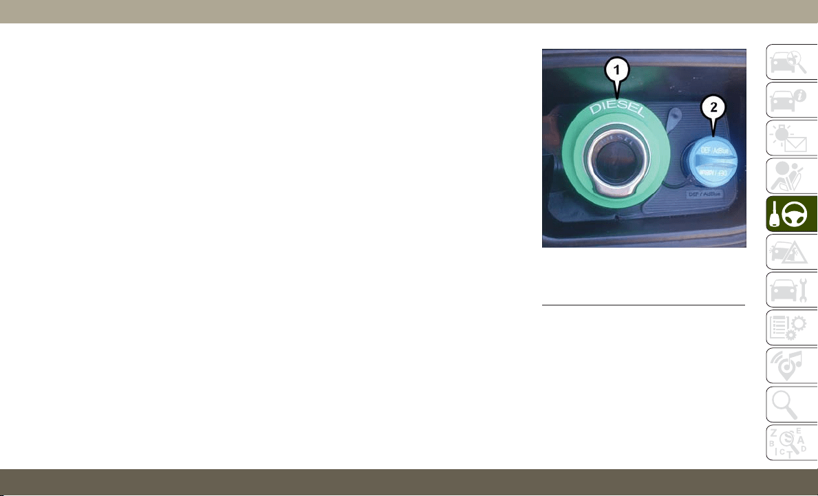
Diesel Exhaust Fluid Storage
Diesel Exhaust Fluid (DEF) is considered a
very stable product with a long shelf life.
If DEF is kept in temperatures between
10° and 90°F (-12° and 32°C), it will last a
minimum of one year.
DEF is subject to freezing at the lowest tem-
peratures. For example, DEF may freeze at
temperatures at or below 12° F (-11° C). The
system has been designed to operate in this
environment.
NOTE:
When working with DEF, it is important to
know that:
• Any containers or parts that come into con-
tact with DEF must be DEF compatible
(plastic or stainless steel). Copper, brass,
aluminum, iron or non-stainless steel
should be avoided as they are subject to
corrosion by DEF.
• If DEF is spilled, it should be wiped up
completely.
Adding Diesel Exhaust Fluid
The DEF gauge (located on the instrument
cluster display) will display the level of DEF
remaining in the tank. Refer to “Instrument
Cluster Display” in “Getting To Know Your
Instrument Panel” for further information.
NOTE:
Driving conditions (altitude, vehicle speed,
load, etc.) will effect the amount of DEF that
is used in your vehicle.
DEF Fill Procedure
NOTE:
Refer to “Fluids And Lubricants” in the
“Technical Specifications” section for the
correct fluid type.
1. Remove cap from DEF fill inlet (located in
fuel door).
2. Insert DEF fill adapter/nozzle into DEF fill
inlet.
DEF Filler Cap And Fuel Fill
1 — Diesel Fuel Filler
2 — Diesel Exhaust Fluid Filler
193

NOTE:
• The DEF gauge may take up to five
seconds to update after adding a gallon
or more of Diesel Exhaust Fluid (DEF)
to the DEF tank. If you have a fault
related to the DEF system, the gauge
may not update to the new level. See an
authorized dealer for service.
• The DEF gauge may also not immedi-
ately update after a refill if the tem-
perature of the DEF fluid is below 12F
(-11C). The DEF line heater will possi-
bly warm up the DEF fluid and allow the
gauge to update after a period of run
time. Under very cold conditions, it is
possible that the gauge may not reflect
the new fill level for several drives.
CAUTION!
•
To avoid DEF spillage, and possible dam-
age to the DEF tank from overfilling, do
not “top off” the DEF tank after filling.
• DO NOT OVERFILL. DEF will freeze be-
low 12ºF (-11ºC). The DEF system is
designed to work in temperatures below
the DEF freezing point, however, if the
tank is overfilled and freezes, the system
could be damaged.
• When DEF is spilled, clean the area
immediately with water and use an ab-
sorbent material to soak up the spills on
the ground.
• Do not attempt to start your engine if
DEF is accidentally added to the diesel
fuel tank as it can result in severe dam-
age to your engine, including but not
limited to failure of the fuel pump and
injectors.
CAUTION!
• Never add anything other than DEF to
the tank – especially any form of hydro-
carbon such as diesel fuel, fuel system
additives, gasoline, or any other
petroleum-based product. Even a very
small amount of these, less than
100 parts per million or less than 1 oz.
(30 ml) per 78 gallons (295 liters) will
contaminate the entire DEF system and
will require replacement. If owners use a
container, funnel or nozzle when refilling
the tank, it should either be new or one
that is has only been used for adding
DEF. Mopar provides an attachable
nozzle with its DEF for this purpose.
3. Stop filling the DEF tank immediately
when any of the following happen: DEF
stops flowing from the fill bottle into the
DEF fill inlet, DEF splashes out the fill
inlet, or a DEF pump nozzle automatically
shuts off.
4. Reinstall cap onto DEF fill inlet.
STARTING AND OPERATING
194

TRAILER TOWING
Trailer Towing Weights (Maximum Trailer
Weight Ratings) — Non SRT
The following chart provides the maximum
trailer weight ratings towable for your given
drivetrain:
Engine Model Frontal Area Max. GTW (Gross Trailer Wt.)
Max. Trailer Tongue Wt.
(See Note)
3.6L (Std Cooling) 4x2 55 sq ft (5.11 sq m) 3,500 lbs (1,587 kg) 350 lbs (158 kg)
3.6L (Std Cooling) 4x4 55 sq ft (5.11 sq m) 3,500 lbs (1,587 kg) 350 lbs (158 kg)
3.6L (HD Cooling) 4x2 55 sq ft (5.11 sq m) 6,200 lbs (2,812 kg) 620 lbs (281 kg)
3.6L (HD Cooling) 4x4 55 sq ft (5.11 sq m) 6,200 lbs (2,812 kg) 620 lbs (281 kg)
5.7L (Std Cooling) 4x4 55 sq ft (5.11 sq m) 5,000 lbs (2,267 kg) 500 lbs (226 kg)
5.7L (HD Cooling) 4x4 55 sq ft (5.11 sq m) 7,200 lbs (3,265 kg) 720 lbs (326 kg)
Refer to local laws for maximum trailer towing speeds.
NOTE:
The trailer tongue weight must be considered
as part of the combined weight of occupants
and cargo, and should never exceed the
weight referenced on the Tire and Loading
Information placard. Refer to “Tires” in “Ser-
vicing And Maintenance” for further informa-
tion. The addition of passengers and cargo
may require reducing trailer tongue load and
Gross Trailer Weight (GTW). Redistributing
cargo (to the trailer) may be necessary to
avoid exceeding Rear Gross Axle Weight Rat-
ing (GAWR) of 3,700 lbs (1,678 kg).
195

Trailer Towing Weights (Maximum Trailer
Weight Ratings) — Diesel
The following chart provides the maximum
trailer weight ratings towable for your given
drivetrain:
Engine Model Frontal Area Max. GTW (Gross Trailer Wt.)
Max. Trailer Tongue Wt.
(See Note)
3.0L Diesel 4x2 55 sq ft (5.11 sq m) 7,400 lbs (3,356 kg) 740 lbs (335 kg)
3.0L Diesel 4x4 55 sq ft (5.11 sq m) 7,200 lbs (3,265 kg) 720 lbs (326 kg)
Refer to local laws for maximum trailer towing speeds.
NOTE:
The trailer tongue weight must be considered
as part of the combined weight of occupants
and cargo, and should never exceed the
weight referenced on the Tire and Loading
Information placard. Refer to “Tires” in “Ser-
vicing And Maintenance” for further informa-
tion. The addition of passengers and cargo
may require reducing trailer tongue load and
Gross Trailer Weight (GTW). Redistributing
cargo (to the trailer) may be necessary to
avoid exceeding Rear Gross Axle Weight Rat-
ing (GAWR) of 3,700 lbs (1 678 kg).
STARTING AND OPERATING
196

Trailer Towing Weights (Maximum Trailer Weight Ratings) — SRT
Engine/Transmission
GCWR (Gross Combined Wt.
Rating)
Frontal Area Max. GTW (Gross Trailer Wt.)
Max. Trailer Tongue Wt.
(See Note)
6.2L Supercharged
Automatic
12,600 lbs (5,715 kg) 55 sq ft (5.11 sq m) 7,200 lbs (3,265 kg) 720 lbs (327 kg)
6.4L Automatic 12,600 lbs (5,715 kg) 55 sq ft (5.11 sq m) 7,200 lbs (3,265 kg) 720 lbs (327 kg)
Refer to local laws for maximum trailer towing speeds.
NOTE:
• The trailer tongue weight must be consid-
ered as part of the combined weight of
occupants and cargo, and should never
exceed the weight referenced on the Tire
and Loading Information placard. Refer to
“Tires” in “Servicing And Maintenance” for
further information.
• The manufacturer does not recommend us-
ing the run flat feature while driving a
vehicle loaded at full capacity or towing a
trailer.
197
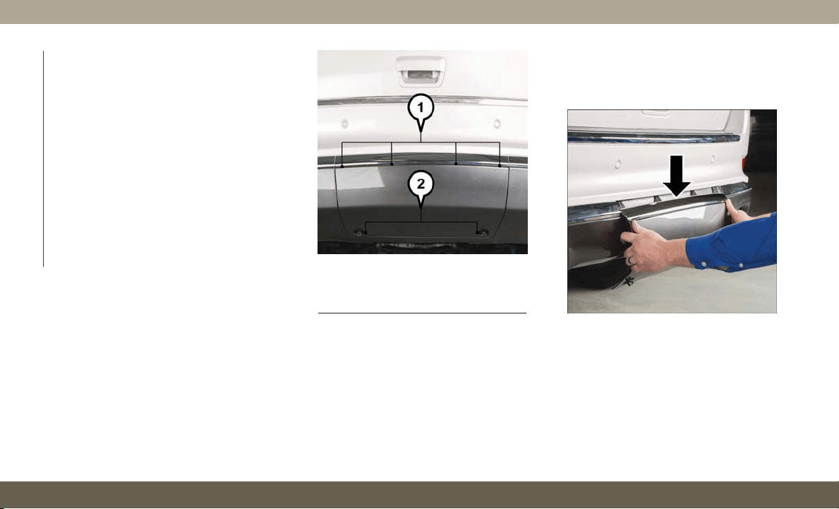
Trailer Hitch Receiver Cover Removal
(Summit Models) — If Equipped
Your vehicle may be equipped with a trailer
hitch receiver cover, this must be removed to
access the trailer hitch receiver (if equipped).
This hitch receiver cover is located at the
bottom center of the rear fascia.
1. Turn the two locking retainers located at
the bottom of the hitch receiver cover a
1/4 turn counterclockwise.
NOTE:
Use a suitable tool such as a coin in the
slot of the locking retainer if needed for
added leverage.
2. Pull the bottom of the cover outward (to-
wards you), pull downwards to disengage
the tabs located at the top of the hitch
receiver cover.
To reinstall the hitch receiver cover after
towing repeat the procedure in reverse order.
Hitch Receiver Cover
1
— Hitch Receiver Cover Tab Locations
2 — Locking Retainers
Hitch Receiver Cover
STARTING AND OPERATING
198
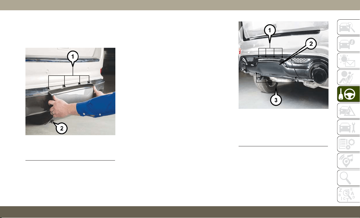
NOTE:
Be sure to engage all tabs of the hitch re-
ceiver cover in the bumper fascia prior to
installation.
Trailer Hitch Receiver Cover Removal
(SRT Models) — If Equipped
Your vehicle may be equipped with a trailer
hitch receiver cover, this must be removed to
access the trailer hitch receiver (if equipped).
This hitch receiver cover is located at the
bottom center of the rear fascia.
1. Turn the two locking retainers located at
the bottom of the hitch receiver cover a
1/4 turn counterclockwise.
NOTE:
Use a suitable tool such as a coin in the
slot of the locking retainer if needed for
added leverage.
Hitch Receiver Cover
1
— Hitch Receiver Cover Tab Locations
2 — Locking Retainers
Hitch Receiver Cover
1 — Hitch Receiver Cover Retaining
Tabs
2 — Hitch Receiver Cover
3 — Locking Retainers
199
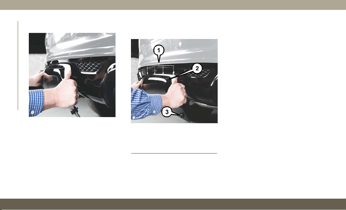
2. Pull the bottom of the cover outward (to-
wards you).
3. Lower back down to disengage the tabs
located at the top of the hitch receiver
cover and then pull outwards to remove.
To reinstall the hitch receiver cover after
towing repeat the procedure in reverse order.
NOTE:
Be sure to engage all tabs of the hitch re-
ceiver cover in the bumper fascia prior to
installation.
Hitch Receiver Cover
Hitch Receiver Cover
1
— Hitch Receiver Cover Retaining Tabs
2 — Hitch Receiver Cover
3 — Locking Retainer
STARTING AND OPERATING
200

RECREATIONAL TOWING (BEHIND MOTORHOME, ETC.)
Towing This Vehicle Behind Another Vehicle
Towing Condition Wheels OFF The Ground Two-Wheel Drive Models Four-Wheel Drive Models
Without 4-LO Range
Four-Wheel Drive Models With 4-LO
Range
Flat Tow NONE NOT ALLOWED NOT ALLOWED
See Instructions
•
Transmission in PARK
• Transfer case in NEUTRAL (N)
• Tow in forward direction
Dolly Tow Front
NOT ALLOWED NOT ALLOWED NOT ALLOWED
Rear OK
NOT ALLOWED NOT ALLOWED
On Trailer ALL OK OK OK
NOTE:
Recreational towing is not allowed on SRT ve-
hicles.
These vehicles may be towed on a flatbed or
vehicle trailer provided all four wheels are OFF
the ground.
NOTE:
• When towing your vehicle, always follow
applicable state and provincial laws. Con-
tact state and provincial Highway Safety
offices for additional details.
• Vehicles equipped with Quadra-Lift must
be placed in Transport Mode before tying
them down (from the body) on a trailer or
flatbed truck. Refer to “Quadra-Lift” in
“Starting and Operating” for more informa-
tion. If the vehicle cannot be placed in
Transport mode (for example, engine will
not run), tie-downs should be fastened over
the tires using specific straps (not to the
body). Failure to follow these instructions
may cause fault codes to be set and/or
cause loss of proper tie-down tension.
201

Recreational Towing — Two Wheel Drive
Models
DO NOT flat tow this vehicle. Damage to the
drivetrain will result.
Recreational towing (for two-wheel drive
models) is allowed ONLY if the rear wheels
are OFF the ground. This may be accom-
plished using a tow dolly or vehicle trailer.
If using a tow dolly, follow this procedure:
1. Properly secure the dolly to the tow ve-
hicle, following the dolly manufacturer's
instructions.
NOTE:
If vehicle is equipped with Quadra-Lift air
suspension, ensure the vehicle is set to
Normal Ride Height.
2. Drive the rear wheels onto the tow dolly.
3. Firmly apply the parking brake. Shift the
transmission into PARK.
4. Turn the ignition OFF.
5. Properly secure the rear wheels to the
dolly, following the dolly manufacturer’s
instructions.
6. Install a suitable clamping device, de-
signed for towing, to secure the front
wheels in the straight position.
CAUTION!
Towing with the rear wheels on the ground
will cause severe transmission damage.
Damage from improper towing is not cov-
ered under the New Vehicle Limited War-
ranty.
Recreational Towing — Quadra-Trac I
(Single-Speed Transfer Case) Four-Wheel
Drive Models
Recreational towing is not allowed. These
models do not have a NEUTRAL (N) position
in the transfer case.
NOTE:
This vehicle may be towed on a flatbed or
vehicle trailer provided all four wheels are OFF
the ground.
CAUTION!
Towing this vehicle in violation of the
above requirements can cause severe
transmission and/or transfer case damage.
Damage from improper towing is not cov-
ered under the New Vehicle Limited War-
ranty.
Recreational Towing — Quadra–Trac II/
Quadra–Drive II Four-Wheel Drive
Models
The transfer case must be shifted into NEU-
TRAL (N) and the transmission must be in
PARK for recreational towing. The NEUTRAL
(N) selection button is adjacent to the trans-
fer case selector switch. Shifts into and out of
transfer case NEUTRAL (N) can take place
with the selector switch in any mode position.
CAUTION!
• DO NOT dolly tow any 4WD vehicle.
Towing with only one set of wheels on
the ground (front or rear) will cause
STARTING AND OPERATING
202
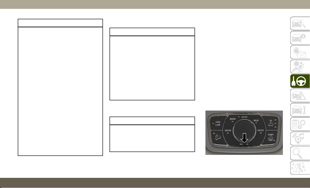
CAUTION!
severe transmission and/or transfer case
damage. Tow with all four wheels either
ON the ground, or OFF the ground (using
a vehicle trailer).
• Tow only in a forward direction. Towing
this vehicle backwards can cause severe
damage to the transfer case.
• The transmission must be in PARK for
recreational towing.
• Before recreational towing, perform the
procedure outlined under “Shifting into
NEUTRAL (N)” to be certain that the
transfer case is fully in NEUTRAL (N).
Otherwise, internal damage will result.
• Towing this vehicle in violation of the
above requirements can cause severe
transmission and/or transfer case dam-
age. Damage from improper towing is
not covered under the New Vehicle Lim-
ited Warranty.
• Do not use a bumper-mounted clamp-on
tow bar on your vehicle. The bumper
face bar will be damaged.
Shifting Into NEUTRAL (N)
WARNING!
You or others could be injured or killed if
you leave the vehicle unattended with the
transfer case in the NEUTRAL (N) position
without first fully engaging the parking
brake. The transfer case NEUTRAL (N)
position disengages both the front and rear
driveshafts from the powertrain and will
allow the vehicle to roll, even if the trans-
mission is in PARK. The parking brake
should always be applied when the driver
is not in the vehicle.
Use the following procedure to prepare your
vehicle for recreational towing.
CAUTION!
It is necessary to follow these steps to be
certain that the transfer case is fully in
NEUTRAL (N) before recreational towing
to prevent damage to internal parts.
1. Bring the vehicle to a complete stop on
level ground, with the engine running.
2. Press and hold the brake pedal.
3. Shift the transmission into NEUTRAL.
4. If vehicle is equipped with Quadra-Lift air
suspension, ensure the vehicle is set to
Normal Ride Height.
5. Using a ballpoint pen or similar object,
push and hold the recessed transfer case
NEUTRAL (N) button (located by the se-
lector switch) for four seconds. The light
behind the N symbol will blink, indicating
shift in progress. The light will stop blink-
ing (stay on solid) when the shift to NEU-
TRAL (N) is complete. A “FOUR WHEEL
DRIVE SYSTEM IN NEUTRAL” message
will appear in the instrument cluster.
NEUTRAL (N) Switch
203

6. After the shift is completed and the NEU-
TRAL (N) light stays on, release the NEU-
TRAL (N) button.
7. Shift the transmission into REVERSE.
8. Release the brake pedal for five seconds
and ensure that there is no vehicle
movement.
9. Press and hold the brake pedal. Shift the
transmission back into NEUTRAL.
10. Firmly apply the parking brake.
11. With the transmission and transfer case
in NEUTRAL, push and hold the EN-
GINE START/STOP button until the en-
gine turns off.
12. Place the transmission gear selector in
PARK. Release the brake pedal.
13. Push the ENGINE STOP/START button
twice (without pressing the brake pedal),
to turn the ignition to the OFF mode.
14. Attach the vehicle to the tow vehicle
using a suitable tow bar.
15. Release the parking brake.
NOTE:
• Steps 1 through 4 are requirements that
must be met before pushing the NEUTRAL
(N) button, and must continue to be met
until the shift has been completed. If any of
these requirements are not met before
pushing the NEUTRAL (N) button or are no
longer met during the shift, then the NEU-
TRAL (N) indicator light will flash continu-
ously until all requirements are met or until
the NEUTRAL (N) button is released.
• The ignition must be in the ON/RUN mode
for a shift to take place and for the position
indicator lights to be operable. If the igni-
tion is not in the ON/RUN mode, the shift
will not take place and no position indicator
lights will be on or flashing.
• A flashing NEUTRAL (N) position indicator
light indicates that shift requirements have
not been met.
• If the vehicle is equipped with Quadra-Lift
air suspension, the engine should be
started and left running for a minimum of
60 seconds (with all the doors closed) at
least once every 24 hours. This process
allows the air suspension to adjust the
vehicle’s ride height to compensate for
temperature effects.
Shifting Out Of NEUTRAL (N)
Use the following procedure to prepare your
vehicle for normal usage.
1. Bring the vehicle to a complete stop,
leaving it connected to the tow vehicle.
2. Firmly apply the parking brake.
3. Start the engine.
4. Press and hold the brake pedal.
5. Shift the transmission into NEUTRAL.
6. Using a ballpoint pen or similar object,
push and hold the recessed transfer case
NEUTRAL (N) button (located by the se-
lector switch) for one second.
STARTING AND OPERATING
204
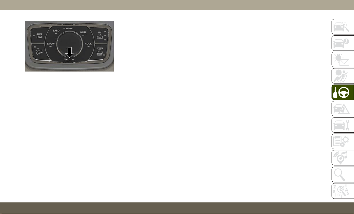
7. When the NEUTRAL (N) indicator light
turns off, release the NEUTRAL (N) but-
ton. After the NEUTRAL (N) button has
been released, the transfer case will shift
to the position indicated by the selector
switch.
8. Shift the transmission into PARK. Turn
the engine OFF.
9. Release the brake pedal.
10. Disconnect vehicle from the tow vehicle.
11. Start the engine.
12. Press and hold the brake pedal.
13. Release the parking brake.
14. Shift the transmission into DRIVE, re-
lease the brake pedal, and check that
the vehicle operates normally.
NOTE:
• Steps 1 through 5 are requirements that
must be met before pushing the NEUTRAL
(N) button, and must continue to be met
until the shift has been completed. If any of
these requirements are not met before
pushing the NEUTRAL (N) button or are no
longer met during the shift, the NEUTRAL
(N) indicator light will flash continuously
until all requirements are met or until the
NEUTRAL (N) button is released.
• The ignition must be in the ON/RUN mode
for a shift to take place and for the position
indicator lights to be operable. If the igni-
tion is not in the ON/RUN mode, the shift
will not take place and no position indicator
lights will be on or flashing.
• A flashing NEUTRAL (N) position indicator
light indicates that shift requirements have
not been met.
NEUTRAL (N) Switch
205

HAZARD WARNING
FLASHERS
The Hazard Warning flasher switch is located on
the switch bank just above the climate controls.
Push the switch to turn on the
Hazard Warning flasher. When the
switch is activated, all directional
turn signals will flash on and off to
warn oncoming traffic of an emer-
gency. Push the switch a second time to turn
off the Hazard Warning flashers.
This is an emergency warning system and it
should not be used when the vehicle is in
motion. Use it when your vehicle is disabled
and it is creating a safety hazard for other
motorists.
When you must leave the vehicle to seek
assistance, the Hazard Warning flashers will
continue to operate even though the ignition
is placed in the OFF position.
NOTE:
With extended use, the Hazard Warning
flashers may discharge the battery.
BULB REPLACEMENT
Replacement Bulbs
Interior Bulbs
Bulb Number
Glove Compartment
Lamp
194
Grab Handle Lamp L002825W5W
Overhead Console
Reading Lamps
VT4976
Rear Cargo Lamp 214–2
Visor Vanity Lamp V26377
Underpanel Courtesy
Lamps
906
Instrument Cluster
(General Illumination)
103
Telltale/Hazard Lamp 74
Exterior Bulbs
Bulb Number
Headlamps
(Low Beam) — If
Equipped
H11
Premium Headlamps
(Low/High Beam)
D3S (Service At
Authorized Dealer)
Headlamps (High
Beam) — If Equipped
H9
Premium Park/Turn
Signal Lamp
LED - (Service At
Authorized Dealer)
Premium Daytime
Running Lamp (DRL)
LED - (Service At
Authorized Dealer)
Front Fog Lamps
H11
LED - (Service At
Authorized Dealer)
Front Side Marker —
If Equipped
W5W
Premium Front Side
Marker — If Equipped
LED - (Service At
Authorized Dealer)
Front Park/Turn
Lamp — If Equipped
7444NA (WY28/8W)
Rear Body Side
Backup Lamp
7440 (W21W)
IN CASE OF EMERGENCY
206
Bulb Number
Auxiliary Liftgate
Tail Lamps
LED - (Service At
Authorized Dealer)
Liftgate Backup
Lamps
921 (W16W)
Rear License Lamps
LED - (Service At
Authorized Dealer)
Rear Body Side
Stop/Turn Lamps
3157KRD LCP
(P27/7W)
Rear Body Side
Tail Lamps
LED - (Service At
Authorized Dealer)
CHMSL - Center
High Mounted
Stop Lamp
LED - (Service At
Authorized Dealer)
NOTE:
Numbers refer to commercial bulb types that
can be purchased from your authorized dealer.
If a bulb needs to be replaced, visit your
authorized dealer or refer to the applicable
Service Manual.
Bulb Replacement
High Intensity Discharge Headlamps (HID) —
If Equipped
The headlamps are a type of high voltage
discharge tube. High voltage can remain in
the circuit even with the headlamp switch off
and the key removed. Because of this, you
should not attempt to service a headlamp bulb
yourself. If a headlamp bulb fails, take your
vehicle to an authorized dealer for service.
WARNING!
A transient high voltage occurs at the bulb
sockets of High Intensity Discharge (HID)
headlamps when the headlamp switch is
turned ON. It may cause serious electrical
shock or electrocution if not serviced prop-
erly. See your authorized dealer for service.
NOTE:
On vehicles equipped with High Intensity
Discharge (HID) headlamps, when the head-
lamps are turned on, there is a blue hue to the
lamps. This diminishes and becomes more
white after approximately 10 seconds, as the
system charges.
Halogen Headlamps — If Equipped
NOTE:
Lens fogging can occur under certain atmo-
spheric conditions. This will usually clear as
atmospheric conditions change to allow the
condensation to change back to vapor. Turn-
ing the lamps on will usually accelerate the
clearing process.
1. Open the hood.
2. Access the back of the headlamp.
NOTE:
• The air filter housing must be removed.
• The windshield washer reservoir may
need to be rotated out of the way by
removing the fastener.
• Coolant reservoir (if equipped) will
need to be repositioned by removing the
fasteners, and moving the unit out of
the way.
3. To access the low beam bulb you must
remove the rubber boot seal from back-
side of the lamp housing.
207
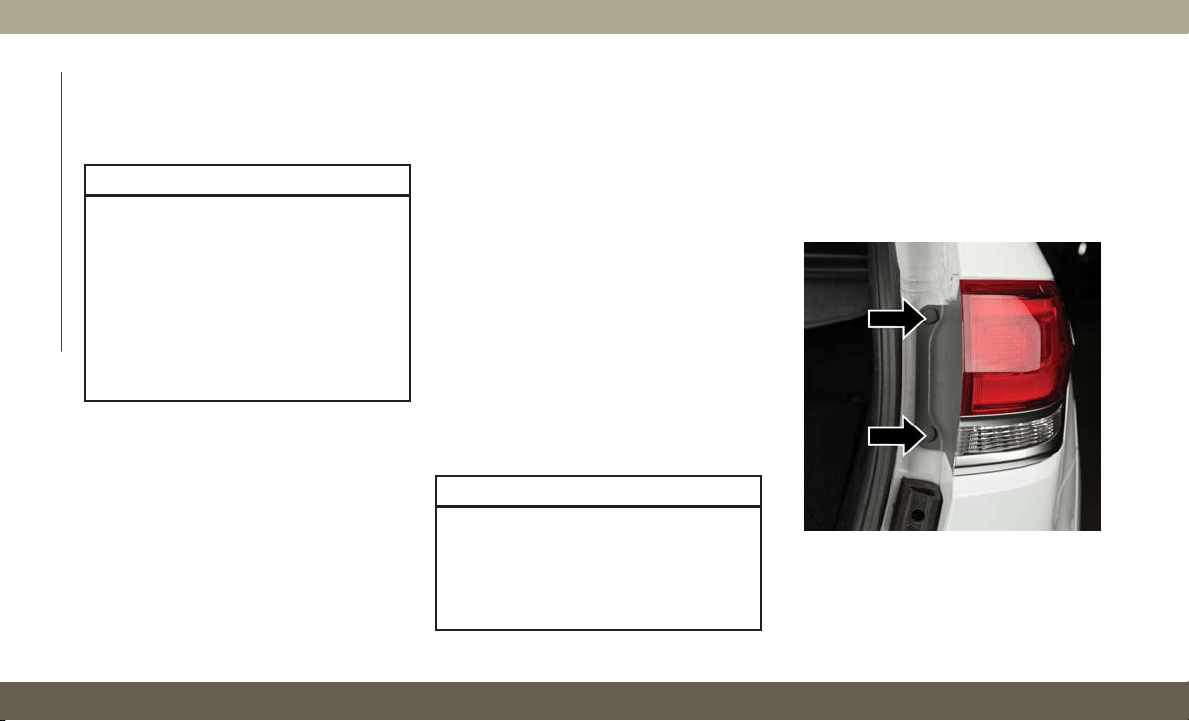
NOTE:
Ensure the rubber boot is properly rein-
stalled to prevent water and moisture from
entering the lamp.
CAUTION!
•
Do not contaminate the bulb glass by
touching it with your fingers or by allow-
ing it to contact other oily surfaces.
Shortened bulb life will result.
• Always use the correct bulb size and type
for replacement. An incorrect bulb size
or type may overheat and cause damage
to the lamp, the bulb socket, or the lamp
wiring.
4. T
urn the low or high beam bulb one–quarter
turn counterclockwise to remove from
housing.
5. Disconnect the electrical connector and
replace the bulb.
Front Turn Signal Lamp
SRT vehicles are equipped with front turn
signal lamps are LEDs. See your authorized
dealer for service.
1. Open the hood.
2. Access the back of the headlamp.
NOTE:
• The air filter housing must be removed.
• The windshield washer reservoir may
need to be rotated out of the way by
removing the fastener.
• Coolant reservoir (if equipped) will
need to be repositioned by removing
the fasteners, and moving the unit out
of the way.
3.
Turn the turn signal bulb one–quarter turn
counterclockwise to remove from housing.
4. Disconnect the electrical connector and
replace the bulb.
CAUTION!
Do not touch the new bulb with your fin-
gers. Oil contamination will severely
shorten bulb life. If the bulb comes in
contact with any oily surface, clean the
bulb with rubbing alcohol.
Front Fog Lamps
Please see your authorized dealer for service.
Rear Tail, Stop, and Turn Signal Lamps
1. Raise the liftgate.
2. Remove the two push-pins from the tail
lamp housing.
3. Grasp the tail lamp and pull firmly rear-
ward to disengage the lamp from the ap-
erture panel.
Tail Lamp Push Pins
IN CASE OF EMERGENCY
208
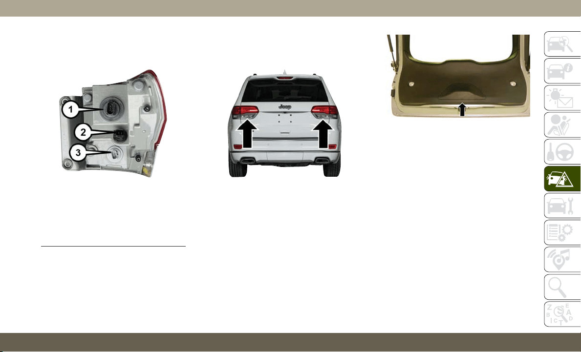
4.
Twist socket counter clockwise and remove
from lamp.
5. Pull the bulb to remove it from the socket.
6. Replace the bulb, reinstall the socket,
and reattach the lamp assembly.
Rear Liftgate Mounted Tail Lamp
1. Raise the liftgate.
2. Use a suitable tool to pry the lower trim
from the liftgate.
3. Continue removing the trim.
4. Disconnect the two trim panel lights.
5. Tail lamps are now visible. Rotate sock-
et(s) counter clockwise.
Rear Of Tail Lamp
1 — Rear Turn/Stop Bulb Socket
2
— LED Tail Connector – Do Not Remove
3 — Backup Bulb Socket
Rear Liftgate Tail Lamps
Liftgate Lower Trim
209
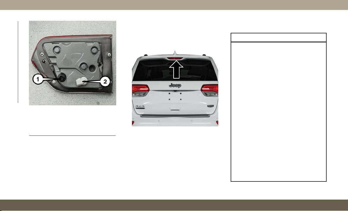
6. Remove/replace bulb(s).
7. Reinstall the socket(s).
8. Reverse process to reinstall the liftgate
trim.
Center High-Mounted Stop Lamp (CHMSL)
The center high mounted stop lamp is an
LED. Service at an authorized dealer.
Rear License Lamp
The rear license lamps are LEDs. See your
authorized dealer for service.
FUSES
WARNING!
• When replacing a blown fuse, always use
an appropriate replacement fuse with
the same amp rating as the original fuse.
Never replace a fuse with another fuse of
higher amp rating. Never replace a
blown fuse with metal wires or any other
material. Do not place a fuse inside a
circuit breaker cavity or vice versa. Fail-
ure to use proper fuses may result in
serious personal injury, fire and/or prop-
erty damage.
• Before replacing a fuse, make sure that
the ignition is off and that all the other
services are switched off and/or disen-
gaged.
• If the replaced fuse blows again, contact
an authorized dealer.
•
If a general protection fuse for safety
systems (air bag system, braking system),
power unit systems (engine system, trans-
mission system) or steering system blows,
contact an authorized dealer.
Rear Of Liftgate Tail Lamp
1 — Auxiliary LED Tail Connector –
Do Not Remove
2 — Backup Bulb Socket
Center High-Mounted Stop Lamp
IN CASE OF EMERGENCY
210
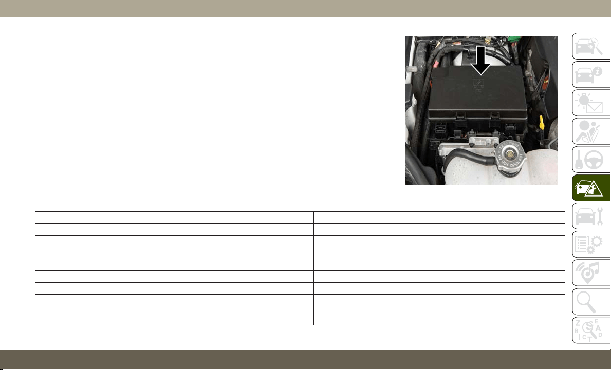
General Information
The fuses protect electrical systems against
excessive current.
When a device does not work, you must check
the fuse element inside the blade fuse for a
break/melt.
Also, please be aware that when using power
outlets for extended periods of time with the
engine off may result in vehicle battery dis-
charge.
Underhood Fuses
The Power Distribution Center is located in
the engine compartment near the battery.
This center contains cartridge fuses, micro
fuses, relays, and circuit breakers. A descrip-
tion of each fuse and component may be
stamped on the inside cover, otherwise the
cavity number of each fuse is stamped on the
inside cover that corresponds to the following
chart.
Cavity Cartridge Fuse Micro Fuse Description
F03 60 Amp Yellow – Radiator Fan — If Equipped
F05 40 Amp Green – Compressor for Air Suspension — If Equipped
F06 40 Amp Green – Anti-lock Brakes/Electronic Stability Control Pump
F07 30 Amp Pink – Starter Solenoid
F09 30 Amp Pink – Diesel Fuel Heater (Diesel Engine Only)/Brake Vacuum Pump
F10 40 Amp Green – Body Controller/Exterior Lighting #2
F11 30 Amp Pink – Trailer Tow Electric Brake — If Equipped
F12 40 Amp Green – Body Controller #3/Power Locks
Power Distribution Center
211

Cavity Cartridge Fuse Micro Fuse Description
F13 40 Amp Green – Blower Motor Front
F14 40 Amp Green – Body Controller #4/Exterior Lighting #1
F15 40 Amp Green – LTR (Low Temperature Radiator) Engine Cooling Pump —
If Equipped
F17 30 Amp Pink – Headlamp Washer — If Equipped
F19 20 Amp Blue – Headrest Solenoid — If Equipped
F20 30 Amp Pink – Passenger Door Module
F22 20 Amp Blue – Engine Control Module
F23 30 Amp Pink – Interior Lights #1
F24 30 Amp Pink – Driver Door Module
F25 30 Amp Pink – Front Wipers
F26 30 Amp Pink – Anti-lock Brakes/Stability Control Module, ECU and Valves
F28 20 Amp Blue – Trailer Tow Backup Lights — If Equipped
F29 20 Amp Blue – Trailer Tow Parking Lights — If Equipped
F30 30 Amp Pink – Trailer Tow (Receptacle) / Trailer Tow (Separate E-Brake) / Trailer
Tow (BUX) — If Equipped
F32 30 Amp Pink – Drive Train Control Module
F34 30 Amp Pink – Slip Differential Control — If Equipped
F35 30 Amp Pink – Sunroof - If Equipped
F36 30 Amp Pink – Rear Defroster
F37 25 Amp Clear – Rear Blower Motor — If Equipped
F38 30 Amp Pink – Power Inverter 115V AC — If Equipped
F39 30 Amp Pink – Power Liftgate — If Equipped
IN CASE OF EMERGENCY
212

Cavity Cartridge Fuse Micro Fuse Description
F40 – 10 Amp Red Daytime Running Lights/Headlamp Leveling
F42 – 20 Amp Yellow Horn
F44 – 10 Amp Red Diagnostic Port
F45 – 5 Amp Tan Cyber Security Gateway
F49 – 10 Amp Red Integrated Central Stack/Climate Control
F50 – 20 Amp Yellow Air Suspension Control Module/Slip Differential - If Equipped
F51 – 15 Amp Blue KIN/RF HUB/Steering Column Lock — If Equipped
F53 – 20 Amp Yellow Trailer Tow – Left Turn/Stop Lights — If Equipped
F56 – 15 Amp Blue Additional Content (Diesel Engine Only)
F57 – 20 Amp Yellow NOX Sensor — If Equipped
F58 – 15 Amp Blue HID Headlamps LH — If Equipped
F59 – 10 Amp Red Purging Pump (Diesel Engine Only)
F60 – 15 Amp Blue Transmission Control Module
F61 – 10 Amp Red Transmission Control Module/PM Sensor (Diesel Engine Only)
F62 – 10 Amp Red Air Conditioning Clutch
F63 – 20 Amp Yellow Ignition Coils / Ignition Coil Capacitors / Short Runner Valve
Actuator — If Equipped (Gas) Urea Heater (Diesel)
F64 – 25 Amp Clear Fuel Injectors/Powertrain
F66 – 10 Amp Red Sunroof/Rain Sensor/Inside Rear View Mirror / USB Port / DSCR /
DTV — If Equipped
F67 – 15 Amp Blue CD/DVD/UCI Port/USB Charging Port
F68 – 20 Amp Yellow Rear Wiper Motor
213

Cavity Cartridge Fuse Micro Fuse Description
F69 – 15 Amp Blue Spotlight Feed — If Equipped
F70 – 20 Amp Yellow Fuel Pump Motor
F71 – 30 Amp Green Amplifier/ANCM — If Equipped
F72 – 10 Amp Red ECM
F73 – 15 Amp Blue HID Headlamp RH — If Equipped
F75 – 10 Amp Red Dual Batt Control — If Equipped
F76 – 10 Amp Red Anti-lock Brakes/Electronic Stability Control
F77 – 10 Amp Red Drivetrain Control Module/Front Axle Disconnect Module —
If Equipped
F78 – 10 Amp Red Engine Control Module/Electric Power Steering
F80 – 10 Amp Red Universal Garage Door Opener/Anti-Intrusion Module —
If Equipped/Siren — If Equipped
F81 – 20 Amp Yellow Trailer Tow Right Turn/Stop Lights — If Equipped
F82 – 10 Amp Red Steering Column Control Module/Cruise Control/DTV — If Equipped
F83 – 10 Amp Red Fuel Door
F84 – 15 Amp Blue Instrument Cluster
F85 – 10 Amp Red Airbag Module
F86 – 10 Amp Red Airbag Module
F87 – 10 Amp Red Air Suspension — If Equipped
F88 – 15 Amp Blue Instrument Panel Cluster/SGW/ITBM — If Equipped
F90/F91 – 20 Amp Yellow Power Outlet (Rear Seats) Selectable
F92 – 10 Amp Red Rear Console Lamp — If Equipped
F93 – 20 Amp Yellow Cigar Lighter
IN CASE OF EMERGENCY
214
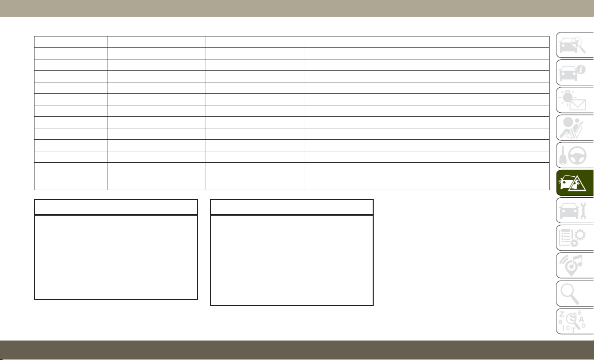
Cavity Cartridge Fuse Micro Fuse Description
F94 – 10 Amp Red Shifter/Transfer Case Module
F95 – 10 Amp Red Rear Camera / Blind Spot Sensor — If Equipped
F96 – 10 Amp Red Rear Seat Heater Switch/Flashlamp Charger — If Equipped
F97 – 20 Amp Yellow Rear Heated Seats & Heated Steering Wheel — If Equipped
F98 – 20 Amp Yellow Ventilated Seats/Front Heated Seats — If Equipped
F99 – 10 Amp Red Climate Control/Driver Assistance Systems Module/HALF/Park Assist
F100 – 10 Amp Red Active Damping — If Equipped
F101 – 15 Amp Blue In Car Temperature Sensor/Humidity Sensor
F102 – 15 Amp Blue Spare
F103 – 10 Amp Red Cabin Heater (Diesel Engine Only)/Rear HVAC — If Equipped
F104 – 20 Amp Yellow Power Outlets (Instrument Panel/Center Console/Rear Cargo —
If Equipped)
CAUTION!
• When installing the power distribution
center cover, it is important to ensure
the cover is properly positioned and fully
latched. Failure to do so may allow water
to get into the power distribution center
and possibly result in an electrical sys-
tem failure.
CAUTION!
• When replacing a blown fuse, it is impor-
tant to use only a fuse having the correct
amperage rating. The use of a fuse with a
rating other than indicated may result in
a dangerous electrical system overload.
If a properly rated fuse continues to
blow, it indicates a problem in the circuit
that must be corrected.
215
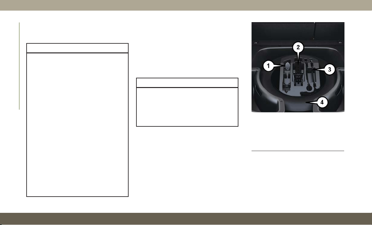
JACKING AND TIRE
CHANGING
WARNING!
• Do not attempt to change a tire on the
side of the vehicle close to moving traf-
fic. Pull far enough off the road to avoid
the danger of being hit when operating
the jack or changing the wheel.
• Being under a jacked-up vehicle is dan-
gerous. The vehicle could slip off the
jack and fall on you. You could be
crushed. Never put any part of your body
under a vehicle that is on a jack. If you
need to get under a raised vehicle, take
it to a service center where it can be
raised on a lift.
• Never start or run the engine while the
vehicle is on a jack.
• The jack is designed to be used as a tool
for changing tires only. The jack should
not be used to lift the vehicle for service
purposes. The vehicle should be jacked
on a firm level surface only. Avoid ice or
slippery areas.
Run Flat Tires — SRT Models
SRT models are equipped with “run flat”
tires. Run flat tires allow the vehicle to be
driven approximately 50 miles (80 km) at
55 mph (88 km/h). Tire service should be
obtained to avoid prolonged run flat feature
usage.
WARNING!
Do not exceed 50 mph (80 km/h) if the
“Tire Pressure Monitoring Telltale Light” is
illuminated. Vehicle handling and braking
may be reduced. You could have a collision
and be severely or fatally injured.
Jack Location
The scissor-type jack and tire changing tools
are located in the rear cargo area, below the
load floor.
Spare Tire Stowage
The spare tire is stowed under the load floor
in the rear cargo area and is secured to the
body with a special wing nut.
Spare Tire/Jack And Tools
1 — Cap-Less Fuel Fill Funnel
2 — Jack
3 — Tire Changing Tools
4 — Spare Tire
IN CASE OF EMERGENCY
216
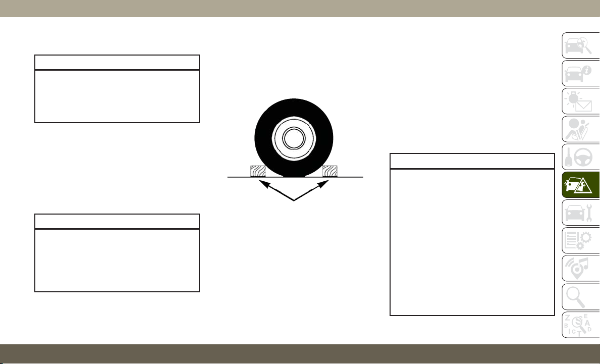
Preparations For Jacking
CAUTION!
Always lift or jack the vehicle from the
correct jacking points. Failure to follow
this information could cause damage to
the vehicle or underbody components.
NOTE:
To assist with changing a spare tire, the air
suspension system (if equipped) has a fea-
ture which allows the automatic leveling to be
disabled.
1. Park the vehicle on a firm, level surface.
Avoid ice or slippery surfaces.
WARNING!
Do not attempt to change a tire on the side
of the vehicle close to moving traffic. Pull
far enough off the road to avoid being hit
when operating the jack or changing the
wheel.
2. Turn on the Hazard Warning flasher.
3. Apply the parking brake.
4. Place the gear selector into PARK.
5. Turn the ignition OFF.
6. Block both the front and rear of the wheel
diagonally opposite of the jacking posi-
tion. For example, if changing the right
front tire, block the left rear wheel.
NOTE:
Passengers should not remain in the ve-
hicle when the vehicle is being jacked.
7. For vehicles equipped with Quadra-Lift,
refer to “Quadra-Lift — If Equipped” in
“Starting And Operating” in the Owner’s
Manual for further information on dis-
abling automatic leveling.
Jacking Instructions
WARNING!
Carefully follow these tire changing warn-
ings to help prevent personal injury or
damage to your vehicle:
• Always park on a firm, level surface as
far from the edge of the roadway as
possible before raising the vehicle.
• Turn on the Hazard Warning flasher.
• Block the wheel diagonally opposite the
wheel to be raised.
• Apply the parking brake firmly and set
the transmission in PARK.
• Never start or run the engine with the
vehicle on a jack.
Wheel Blocked
217
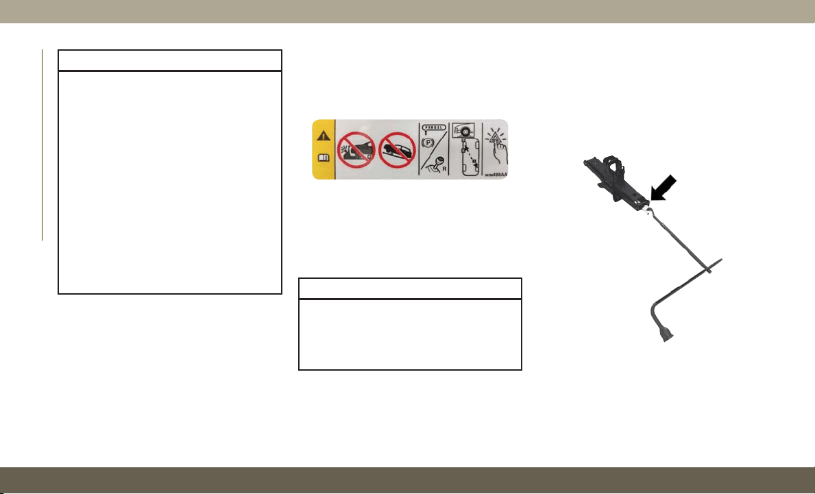
WARNING!
• Do not let anyone sit in the vehicle when
it is on a jack.
• Do not get under the vehicle when it is
on a jack. If you need to get under a
raised vehicle, take it to a service center
where it can be raised on a lift.
• Only use the jack in the positions indi-
cated and for lifting this vehicle during a
tire change.
• If working on or near a roadway, be
extremely careful of motor traffic.
• To assure that spare tires, flat or in-
flated, are securely stowed, spares must
be stowed with the valve stem facing the
ground.
CAUTION!
Do not attempt to raise the vehicle by
jacking on locations other than those indi-
cated in the Jacking Instructions for this
vehicle.
1. Remove the spare tire, jack, and tools
from storage.
2. Loosen (but do not remove) the wheel lug
nuts by turning them to the left, one turn,
while the wheel is still on the ground.
3. Assemble the jack and jacking tools.
Warning Label
Jack And Tools Assembled
IN CASE OF EMERGENCY
218
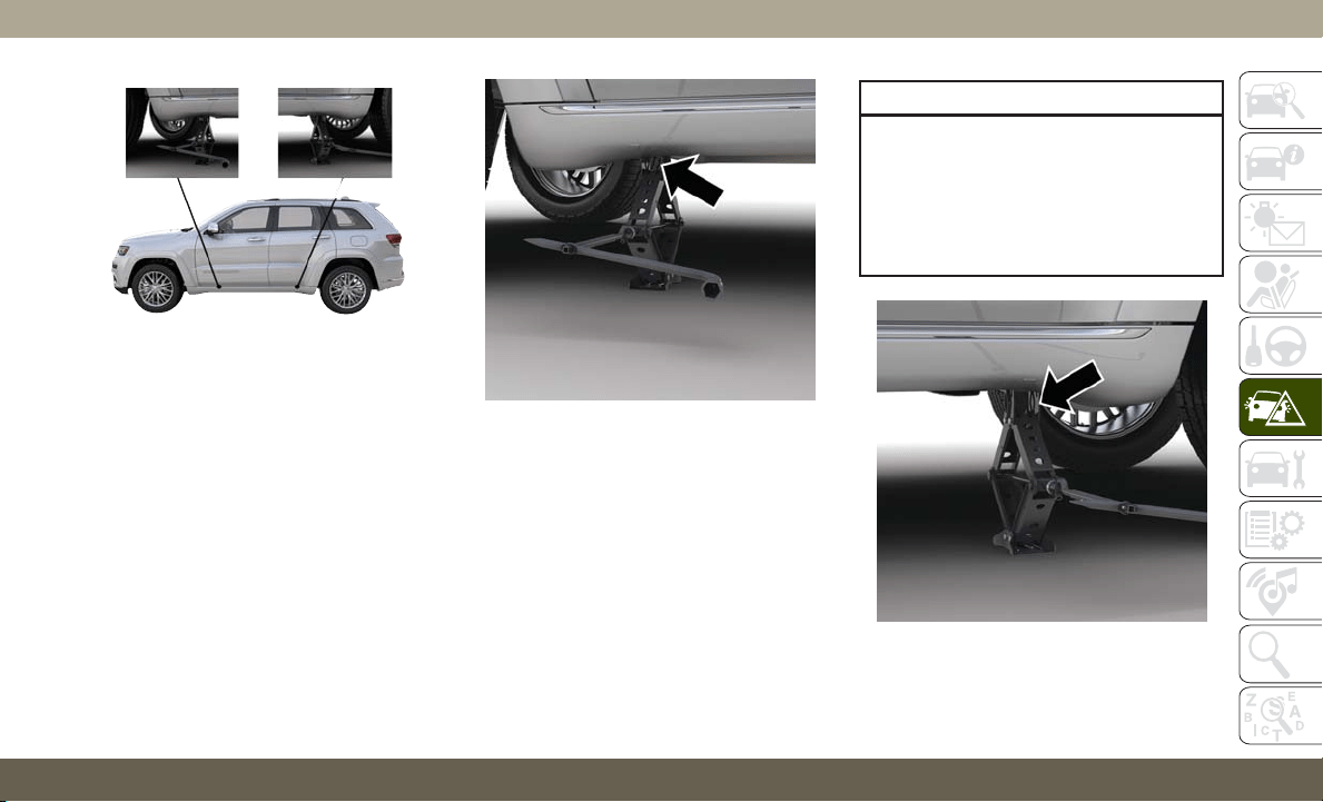
4. For the front axle, place the jack on the
body flange just behind the front tire as
indicated by the triangular lift point sym-
bol on the sill molding. Do not raise the
vehicle until you are sure the jack is fully
engaged.
5. For a rear tire, place the jack in the slot on
the rear tie-down bracket, just forward of
the rear tire (as indicated by the triangular
lift point symbol on the sill molding). Do
not raise the vehicle until you are sure the
jack is fully engaged.
CAUTION!
Do NOT raise the vehicle by the body side
sill molding. Be sure the jack is placed in
the proper engagement location on the
inside of the panel. Damage of the vehicle
may occur if the procedure is not properly
followed.
Jacking Locations
Front Jacking Location
Rear Jacking Location
219
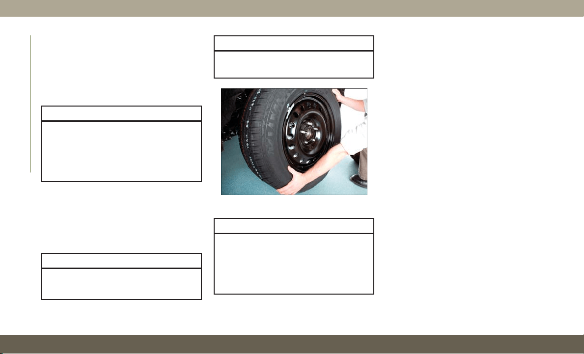
6. Raise the vehicle by turning the jack
screw clockwise. Raise the vehicle only
until the tire just clears the surface and
enough clearance is obtained to install
the spare tire. Minimum tire lift provides
maximum stability.
WARNING!
Raising the vehicle higher than necessary
can make the vehicle less stable. It could
slip off the jack and hurt someone near it.
Raise the vehicle only enough to remove
the tire.
7. Remove the lug nuts and wheel.
8. Position the spare wheel/tire on the ve-
hicle and install the lug nuts with the
cone-shaped end toward the wheel.
Lightly tighten the nuts.
CAUTION!
Be sure to mount the spare tire with the
valve stem facing outward. The vehicle
CAUTION!
could be damaged if the inflatable spare
tire is mounted incorrectly.
WARNING!
To avoid the risk of forcing the vehicle off
the jack, do not tighten the wheel nuts
fully until the vehicle has been lowered.
Failure to follow this warning may result in
serious injury.
9. Lower the vehicle by turning the jack
screw counterclockwise, and remove the
jack and wheel blocks.
10. Finish tightening the lug nuts. Push
down on the wrench while at the end of
the handle for increased leverage.
Tighten the lug nuts in a star pattern
until each nut has been tightened twice.
For correct lug nut torque, refer to
“Torque Specifications” in “Technical
Specifications”. If in doubt about the
correct tightness, have them checked
with a torque wrench by an authorized
dealer or at a service station.
11. Lower the jack to the fully closed posi-
tion and return it and the tools to the
proper positions in the foam tray.
12. Remove the small center cap and se-
curely store the road wheel in the cargo
area.
Installing Spare Wheel/Tire
IN CASE OF EMERGENCY
220
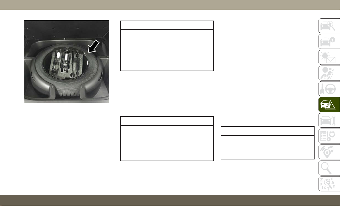
13. Have the aluminum road wheel and tire
repaired as soon as possible, properly
secure the spare tire with the special
wing nut torqued to 3.7 ft-lbs (5 N·m),
reinstall the jack and tool kit foam tray,
and latch the rear load floor cover.
NOTE:
Do not drive with the spare tire installed for
more than 50 miles (80 km) at a max speed
of 50 mph (80 km/h).
WARNING!
A loose tire or jack thrown forward in a
collision or hard stop could endanger the
occupants of the vehicle. Always stow the
jack parts and the spare tire in the places
provided. Have the deflated (flat) tire re-
paired or replaced immediately.
Road Tire Installation
1. Mount the road tire on the axle.
2. Install the remaining lug nuts with the
cone shaped end of the nut toward the
wheel. Lightly tighten the lug nuts.
WARNING!
To avoid the risk of forcing the vehicle off
the jack, do not tighten the wheel nuts
fully until the vehicle has been lowered.
Failure to follow this warning may result in
serious injury.
3. Lower the vehicle to the ground by turning
the jack handle counterclockwise.
4.
Refer to “Torque Specifications” in “Tech-
nical Specifications” for proper lug nut
torque.
5. After 25 miles (40 km), check the lug nut
torque with a torque wrench to ensure that
all lug nuts are properly seated against the
wheel.
JUMP STARTING
If your vehicle has a discharged battery, it can
be jump started using a set of jumper cables
and a battery in another vehicle, or by using a
portable battery booster pack. Jump starting
can be dangerous if done improperly, so
please follow the procedures in this section
carefully.
WARNING!
Do not attempt jump starting if the battery
is frozen. It could rupture or explode and
cause personal injury.
Spare Tire
221
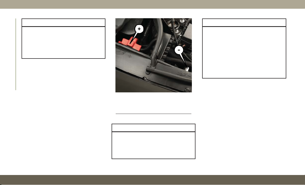
CAUTION!
Do not use a portable battery booster pack
or any other booster source with a system
voltage greater than 12 Volts or damage to
the battery, starter motor, alternator or
electrical system may occur.
NOTE:
When using a portable battery booster pack,
follow the manufacturer's operating instruc-
tions and precautions.
Preparations For Jump Start
The battery in your vehicle is located under
the passenger's front seat. There are remote
terminals located under the hood to assist in
jump starting.
WARNING!
•T
ake care to avoid the radiator cooling fan
whenever the hood is raised. It can start
anytime the ignition switch is ON. You can
be injured by moving fan blades.
WARNING!
• Remove any metal jewelry such as rings,
watch bands and bracelets that could
make an inadvertent electrical contact.
You could be seriously injured.
• Batteries contain sulfuric acid that can
burn your skin or eyes and generate
hydrogen gas which is flammable and
explosive. Keep open flames or sparks
away from the battery.
NOTE:
Be sure that the disconnected cable ends do
not touch each other, or either vehicle, until
properly connected for jump starting.
1. Apply the parking brake, shift the auto-
matic transmission into PARK and turn
the ignition OFF.
2. Turn off the heater, radio, and all unnec-
essary electrical accessories.
3. Remove the protective cover over the re-
mote positive (+) battery post. Pull up-
ward on the cover to remove it.
Jump Starting Locations
(+) — Remote Positive Post
(-) — Remote Negative Post
IN CASE OF EMERGENCY
222
4. If using another vehicle to jump start the
battery, park the vehicle within the jumper
cables reach, apply the parking brake and
make sure the ignition is OFF.
WARNING!
Do not allow vehicles to touch each other
as this could establish a ground connec-
tion and personal injury could result.
Jump Starting Procedure
WARNING!
Failure to follow this jump starting proce-
dure could result in personal injury or
property damage due to battery explosion.
CAUTION!
Failure to follow these procedures could
result in damage to the charging system of
the booster vehicle or the discharged ve-
hicle.
NOTE:
Make sure at all times that unused ends of
jumper cables are not contacting each other
or either vehicle while making connections.
Connecting The Jumper Cables
1. Connect the positive (+) end of the jumper
cable to the remote positive (+) post of the
discharged vehicle.
2. Connect the opposite end of the positive
(+) jumper cable to the positive (+) post of
the booster battery.
3. Connect the negative end (-) of the jumper
cable to the negative (-) post of the
booster battery.
4.
Connect the opposite end of the negative
(-)
jumper cable to the remote negative (-)
post of the vehicle with the discharged
battery.
WARNING!
Do not connect the jumper cable to the
negative (-) post of the discharged battery.
The resulting electrical spark could cause
the battery to explode and could result in
WARNING!
personal injury. Only use the specific
ground point, do not use any other exposed
metal parts.
5. Start the engine in the vehicle that has the
booster battery, let the engine idle a few
minutes, and then start the engine in the
vehicle with the discharged battery.
CAUTION!
Do not run the booster vehicle engine
above 2,000 rpm since it provides no
charging benefit, wastes fuel, and can
damage booster vehicle engine.
6. Once the engine is started, remove the
jumper cables in the reverse sequence:
Disconnecting The Jumper Cables
1. Disconnect the negative (-) end of the
jumper cable from the remote negative (-)
post of the discharged vehicle.
2. Disconnect the opposite end of the nega-
tive (-) jumper cable from the negative (-)
post of the booster battery.
223

3. Disconnect the positive (+) end of the
jumper cable from the positive (+) post of
the booster battery.
4.
Disconnect the opposite end of the positive
(+) jumper cable from the remote positive
(+) post of the discharged vehicle.
5. Reinstall the protective cover over the
remote positive (+) post of the discharged
vehicle.
If
frequent jump starting is required to start
your vehicle you should have the battery and
charging system tested at an authorized dealer.
CAUTION!
Accessories plugged into the vehicle
power outlets draw power from the vehi-
cle’s battery, even when not in use (i.e.,
cellular devices, etc.). Eventually, if
plugged in long enough without engine
operation, the vehicle’s battery will dis-
charge sufficiently to degrade battery life
and/or prevent the engine from starting.
REFUELING IN EMERGENCY
The funnel for the Cap-Less Fuel System is
located in the spare tire storage area. If your
vehicle is out of fuel and an auxiliary fuel can
is needed, insert the funnel into the filler
neck and proceed to fill the vehicle.
For more information on the Cap-Less Fuel
System refer to “Refueling The Vehicle” in
“Starting And Operating”.
IF YOUR ENGINE
OVERHEATS
In any of the following situations, you can
reduce the potential for overheating by taking
the appropriate action.
• On the highways — slow down.
• In city traffic — while stopped, place the
transmission in NEUTRAL, but do not in-
crease the engine idle speed while prevent-
ing vehicle motion with the brakes.
NOTE:
There are steps that you can take to slow
down an impending overheat condition:
• If your air conditioner (A/C) is on, turn it off.
The A/C system adds heat to the engine
cooling system and turning the A/C off can
help remove this heat.
• You can also turn the temperature control
to maximum heat, the mode control to floor
and the blower control to high. This allows
the heater core to act as a supplement to
the radiator and aids in removing heat from
the engine cooling system.
WARNING!
You or others can be badly burned by hot
engine coolant (antifreeze) or steam from
your radiator. If you see or hear steam
coming from under the hood, do not open
the hood until the radiator has had time to
cool. Never try to open a cooling system
pressure cap when the radiator or coolant
bottle is hot.
IN CASE OF EMERGENCY
224
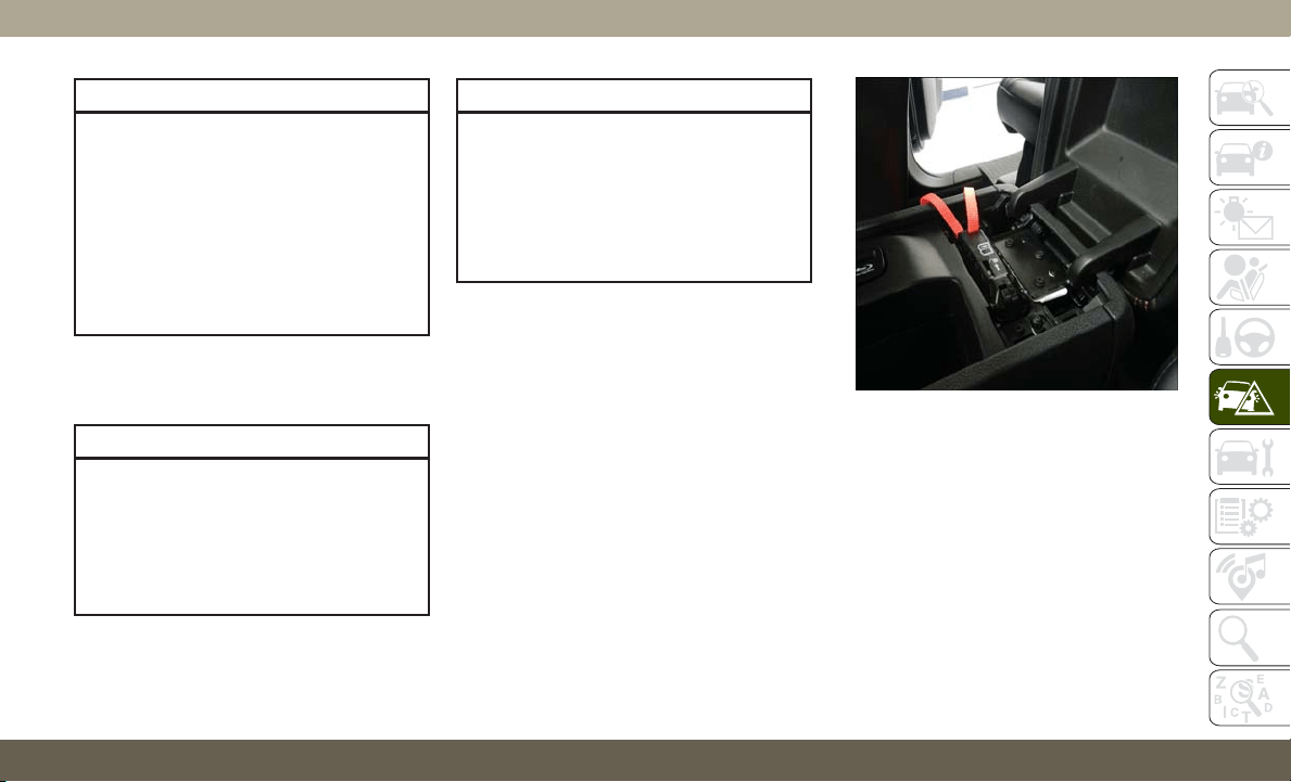
CAUTION!
Driving with a hot cooling system could
damage your vehicle. If the temperature
gauge reads HOT (H), pull over and stop
the vehicle. Idle the vehicle with the air
conditioner turned off until the pointer
drops back into the normal range. If the
pointer remains on HOT (H), and you hear
continuous chimes, turn the engine off
immediately and call for service.
MANUAL PARK RELEASE
WARNING!
Always secure your vehicle by fully apply-
ing the parking brake before activating the
Manual Park Release. In addition, you
should be seated in the driver’s seat with
your foot firmly on the brake pedal when
activating the Manual Park Release. Acti-
WARNING!
vating the Manual Park Release will allow
your vehicle to roll away if it is not secured
by the parking brake, or by proper connec-
tion to a tow vehicle. Activating the
Manual Park Release on an unsecured
vehicle could lead to serious injury or
death for those in or around the vehicle.
In order to move the vehicle in cases where
the transmission will not shift out of PARK
(such as a dead battery), a Manual Park
Release is available.
Follow these steps to use the Manual Park
Release:
1. Firmly apply the parking brake.
2. Open the center console and locate the
Manual Park Release cover, remove it by
snapping the cover away from the console
hinges.
3. Press and maintain firm pressure on the
brake pedal.
4. Using a screwdriver or similar tool, push
the metal latch in towards the tether
strap.
Manual Park Release Cover Removed
225
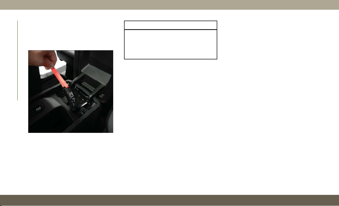
5.
While the metal latch is in the open posi-
tion, pull upward on the tether strap until
the lever clicks and latches in the released
position. The transmission is now out of
PARK and the vehicle can be moved.
CAUTION!
Closing the armrest while the Manual Park
Release is activated may damage the
Manual Park Release mechanism, the
transmission, and/or the armrest.
NOTE:
To prevent the vehicle from rolling uninten-
tionally, firmly apply the parking brake.
T
o Disengage The Manual Park Release Lever:
1. To disengage the Manual Park Release,
apply tension upward while pushing the
release latch towards the tether to unlock
the lever.
2. Once the tension has been released and
the lever has been unlocked, be sure it is
stowed properly and locks into position.
NOTE:
Be sure to replace the cover by snapping it
back in place.
FREEING A STUCK VEHICLE
If your vehicle becomes stuck in mud, sand
or snow, it can often be moved using a rock-
ing motion. Turn the steering wheel right and
left to clear the area around the front wheels.
Push and hold the lock button on the gear
selector. Then, shift back and forth between
DRIVE and REVERSE while gently pressing
the accelerator.
NOTE:
Shifts between DRIVE and REVERSE can
only be achieved at wheel speeds of 5 mph
(8 km/h) or less. Whenever the transmission
remains in NEUTRAL for more than two sec-
onds, you must press the brake pedal to
engage DRIVE or REVERSE.
Use the least amount of accelerator pedal
pressure that will maintain the rocking mo-
tion without spinning the wheels or racing the
engine.
Released Position
IN CASE OF EMERGENCY
226
NOTE:
Push the "ESC Off" switch, to place the Elec-
tronic Stability Control (ESC) system in "Par-
tial Off" mode, before rocking the vehicle.
Refer to “Electronic Brake Control” in
“Safety” in your Owner’s Manual for further
information. Once the vehicle has been freed,
push the "ESC Off" switch again to restore
"ESC On" mode.
WARNING!
Fast spinning tires can be dangerous.
Forces generated by excessive wheel
speeds may cause damage, or even failure,
of the axle and tires. A tire could explode
and injure someone. Do not spin your ve-
hicle's wheels faster than 30 mph
(48 km/h) or for longer than 30 seconds
continuously without stopping when you
are stuck and do not let anyone near a
spinning wheel, no matter what the speed.
CAUTION!
• Racing the engine or spinning the
wheels may lead to transmission over-
heating and failure. Allow the engine to
idle with the transmission in NEUTRAL
for at least one minute after every five
rocking-motion cycles. This will mini-
mize overheating and reduce the risk of
transmission failure during prolonged
efforts to free a stuck vehicle.
• When “rocking” a stuck vehicle by shift-
ing between DRIVE and REVERSE, do
not spin the wheels faster than 15 mph
(24 km/h), or drivetrain damage may
result.
• Revving the engine or spinning the
wheels too fast may lead to transmission
overheating and failure. It can also dam-
age the tires. Do not spin the wheels
above 30 mph (48 km/h) while in gear
(no transmission shifting occurring).
TOWING A DISABLED
VEHICLE
This section describes procedures for towing
a disabled vehicle using a commercial towing
service. If the transmission and drivetrain are
operable, disabled vehicles may also be
towed as described under “Recreational Tow-
ing” in the “Starting And Operating” section
of the Owner’s Manual.
NOTE:
Vehicles equipped with Quadra-Lift must be
placed in Transport mode, before tying them
down (from the body) on a trailer or flatbed
truck. Refer to the section on Quadra-Lift
for more information. If the vehicle cannot
be placed in Transport mode (for example,
engine will not run), tie-downs should be
fastened over the tires using specific tire
tie-down nets. Failure to follow these instruc-
tions may cause fault codes to be set and/or
cause loss of proper tie-down tension.
227
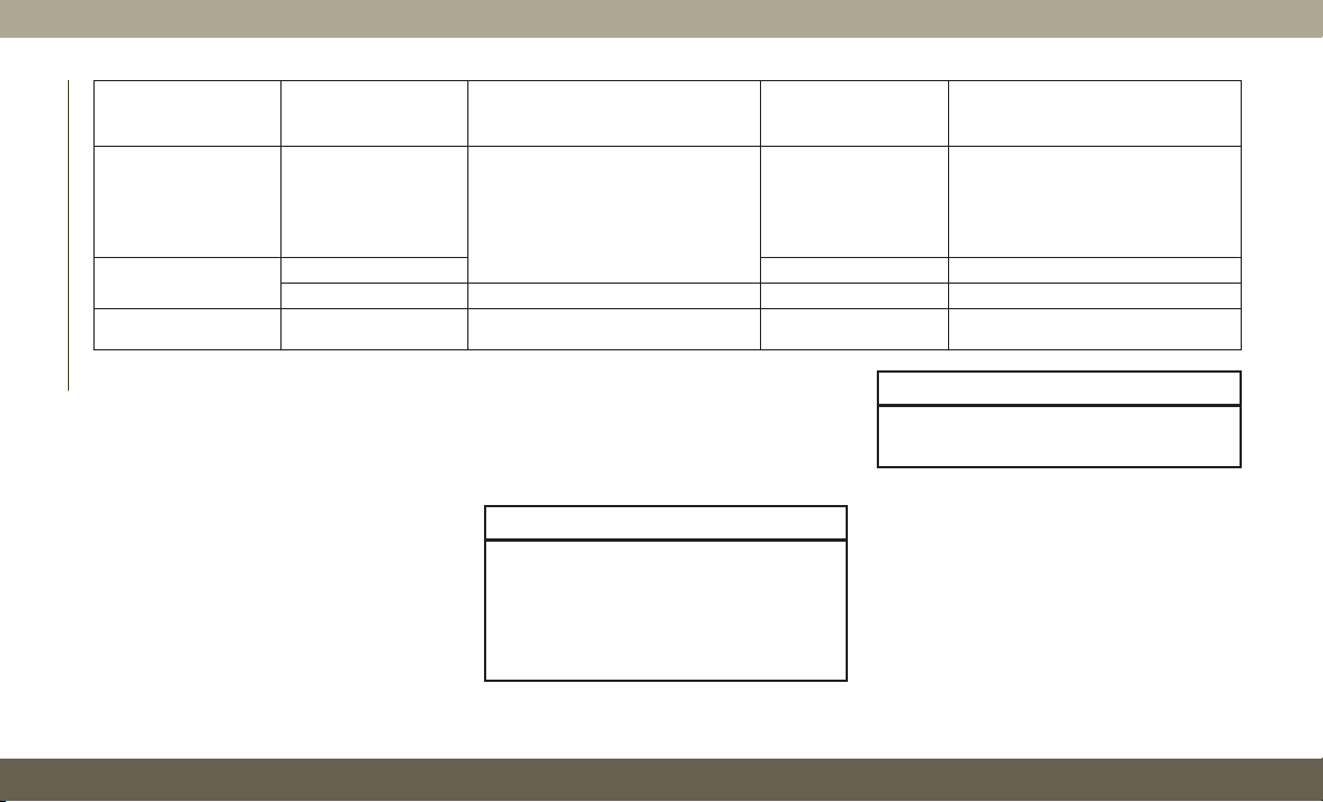
Towing Condition Wheels OFF The Ground Two-Wheel Drive Models
Four-Wheel Drive
Models Without
4WD LOW Range
Four-Wheel Drive Models With
4WD LOW Range
Flat Tow NONE
If transmission is operable:
•
Transmission in NEUTRAL
• 30 mph (48 km/h) max speed
• 30 miles (48 km) max distance
NOT ALLOWED
See instructions in “Recreational
Towing”
•
Transmission in PARK
• Transfer case in NEUTRAL (N)
• Tow in forward direction
Wheel Lift Or
Dolly Tow
Front
NOT ALLOWED NOT ALLOWED
Rear OK
NOT ALLOWED NOT ALLOWED
On Trailer ALL BEST METHOD OK BEST METHOD
Proper towing or lifting equipment is required
to prevent damage to your vehicle. Use only
tow bars and other equipment designed for
this purpose, following equipment manufac-
turer’s instructions. Use of safety chains is
mandatory. Attach a tow bar or other towing
device to main structural members of the
vehicle, not to bumpers or associated brack-
ets. State and local laws regarding vehicles
under tow must be observed.
If you must use the accessories (wipers, de-
frosters, etc.) while being towed, the ignition
must be in the ON/RUN mode, not the ACC
mode.
If the key fob is unavailable, or the vehicle's
battery is discharged, refer to “Manual Park
Release” in this section for instructions on
shifting the transmission out of PARK for
towing.
CAUTION!
• Do not use sling type equipment when
towing. Vehicle damage may occur.
• When securing the vehicle to a flat bed
truck, do not attach to front or rear
suspension components. Damage to
CAUTION!
your vehicle may result from improper
towing.
NOTE:
SRT vehicles and 4WD models without 4WD
LOW range should only be towed with all four
wheels OFF the ground.
IN CASE OF EMERGENCY
228
Two-Wheel Drive Models
The manufacturer recommends towing your
vehicle with all four wheels OFF the ground
using a flatbed.
If flatbed equipment is not available, and the
transmission is operable, the vehicle may be
towed (with rear wheels on the ground) under
the following conditions:
• The transmission must be in NEUTRAL.
Refer to "Manual Park Release" in this sec-
tion for instructions on shifting the trans-
mission to NEUTRAL when the engine is
off.
• The towing speed must not exceed 30 mph
(48 km/h).
• The towing distance must not exceed
30 miles (48 km).
If the transmission is not operable, or the
vehicle must be towed faster than 30 mph
(48 km/h) or farther than 30 miles (48 km),
tow with the rear wheels OFF the ground.
Acceptable methods are to tow the vehicle on
a flatbed, or with the front wheels raised and
the rear wheels on a towing dolly, or (when
using a suitable steering wheel stabilizer to
hold the front wheels in the straight position)
with the rear wheels raised and the front
wheels on the ground.
CAUTION!
• Towing faster than 30 mph (48 km/h) or
farther than 30 miles (48 km) with rear
wheels on the ground can cause severe
transmission damage. Damage from im-
proper towing is not covered under the
New Vehicle Limited Warranty.
Four-Wheel Drive Models
The manufacturer recommends towing with
all wheels OFF the ground. Acceptable meth-
ods are to tow the vehicle on a flatbed or with
one end of vehicle raised and the opposite
end on a towing dolly.
If flatbed equipment is not available, and the
transfer case is operable, vehicles may be
towed (in the forward direction, with ALL
wheels on the ground), IF the transfer case is
in NEUTRAL (N) and the transmission is in
PARK. Refer to “Recreational Towing” in
“Starting And Operating” in the Owner’s
Manual for detailed instructions.
Vehicles equipped with a single-speed trans-
fer case have no NEUTRAL position, and
therefore must be towed with all four wheels
OFF the ground.
CAUTION!
• Front or rear wheel lifts must not be used
(if the remaining wheels are on the
ground). Internal damage to the trans-
mission or transfer case will occur if a
front or rear wheel lift is used when
towing.
• Towing this vehicle in violation of the
above requirements can cause severe
transmission and/or transfer case dam-
age. Damage from improper towing is
not covered under the New Vehicle Lim-
ited Warranty.
229

Emergency Tow Hooks — If Equipped
If your vehicle is equipped with tow hooks,
there will be one in the rear and two mounted
on the front of the vehicle. The rear hook will
be located on the driver's side of the vehicle.
NOTE:
For off-road recovery, it is recommended to
use both of the front tow hooks to minimize
the risk of damage to the vehicle.
WARNING!
• Do not use a chain for freeing a stuck
vehicle. Chains may break, causing seri-
ous injury or death.
• Stand clear of vehicles when pulling
with tow hooks. Tow straps may become
disengaged, causing serious injury.
CAUTION!
Tow hooks are for emergency use only, to
rescue a vehicle stranded off road. Do not
use tow hooks for tow truck hookup or
highway towing. You could damage your
vehicle.
ENHANCED ACCIDENT
RESPONSE SYSTEM (EARS)
This vehicle is equipped with an Enhanced
Accident Response System.
Please refer to “Occupant Restraint Sys-
tems” in “Safety” for further information on
the Enhanced Accident Response System
(EARS) function.
EVENT DATA RECORDER
(EDR)
This vehicle is equipped with an Event Data
Recorder (EDR). The main purpose of an EDR
is to record data that will assist in under-
standing how a vehicle’s systems performed
under certain crash or near crash-like situa-
tions, such as an air bag deployment or hit-
ting a road obstacle.
Please refer to “Occupant Restraint Sys-
tems” in “Safety” for further information on
the Event Data Recorder (EDR).
IN CASE OF EMERGENCY
230

SCHEDULED SERVICING
Scheduled Servicing — Non-SRT
Your vehicle is equipped with an automatic
oil change indicator system. The oil change
indicator system will remind you that it is
time to take your vehicle in for scheduled
maintenance.
Based on engine operation conditions, the oil
change indicator message will illuminate.
This means that service is required for your
vehicle. Operating conditions such as fre-
quent short-trips, trailer tow, extremely hot or
cold ambient temperatures, and E85 fuel
usage will influence when the “Oil Change
Required” message is displayed. Severe
operating conditions can cause the change
oil message to illuminate as early as
3,500 miles (5,600 km) since last reset.
Have your vehicle serviced as soon as pos-
sible, within the next 500 miles (805 km).
Your authorized dealer will reset the oil
change indicator message after completing
the scheduled oil change.
NOTE:
Under no circumstances should oil change
intervals exceed 10,000 miles (16,000 km),
twelve months or 350 hours of engine run
time, whichever comes first. The 350 hours
of engine run or idle time is generally only a
concern for fleet customers.
Severe Duty All Models
Change Engine Oil at 4,000 miles (6,500 km)
or 350 hours of engine run time if the vehicle is
operated in a dusty and off-road environment,
or is operated predominantly at idle or only very
low engine RPM’s. This type of vehicle use is
considered Severe Duty.
Once A Month Or Before A Long Trip:
• Check engine oil level.
• Check windshield washer fluid level.
• Check the tire inflation pressures and look
for unusual wear or damage.
• Check the fluid levels of the coolant reser-
voir, brake master cylinder and fill as
needed.
• Check function of all interior and exterior
lights
231

Maintenance Plan
Required Maintenance
Refer to the Maintenance Plans on the fol-
lowing pages for required maintenance.
At Every Oil Change Interval As Indicated By Oil Change Indicator System:
•
Change oil and filter.
•
Rotate the tires. Rotate at the first sign of irregular wear, even if it occurs before the oil indicator system turns on.
•
Inspect battery and clean and tighten terminals as required.
•
Inspect brake pads, shoes, rotors, drums, hoses and park brake.
•
Inspect engine cooling system protection and hoses.
•
Inspect exhaust system.
•
Inspect engine air cleaner if using in dusty or off-road conditions.
Mileage or time passed (whichever comes first)
20,000
30,000
40,000
50,000
60,000
70,000
80,000
90,000
100,000
110,000
120,000
130,000
140,000
150,000
Or Years: 2 3 4 5 6 7 8 9 10 11 12 13 14 15
Or Kilometers:
32,000
48,000
64,000
80,000
96,000
112,000
128,000
144,000
160,000
176,000
192,000
208,000
224,000
240,000
Additional Inspections
Inspect the CV joints. X X X X X
Inspect front suspension, tie rod ends, and replace if necessary. X X X X X X X
SERVICING AND MAINTENANCE
232
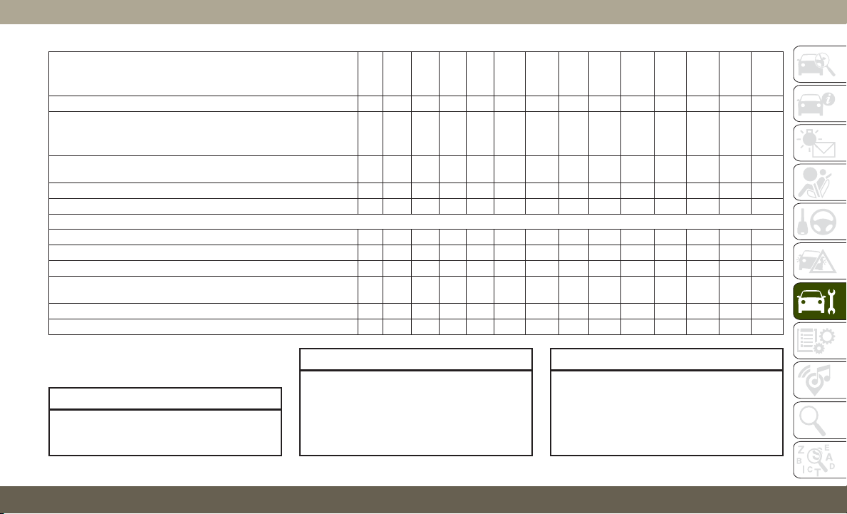
Mileage or time passed (whichever comes first)
20,000
30,000
40,000
50,000
60,000
70,000
80,000
90,000
100,000
110,000
120,000
130,000
140,000
150,000
Or Years: 2 3 4 5 6 7 8 9 10 11 12 13 14 15
Or Kilometers:
32,000
48,000
64,000
80,000
96,000
112,000
128,000
144,000
160,000
176,000
192,000
208,000
224,000
240,000
Inspect the front and rear axle fluid, change if using your vehicle for
police, taxi, fleet, off-road or frequent trailer towing.
XXX X X X X
Inspect the brake linings, parking brake function. X X X X X X X
Inspect transfer case fluid. X X X X
Additional Maintenance
Replace engine air filter. X X X X X
Replace the air conditioning filter. X X X X X X X
Replace spark plugs.** X
Flush and replace the engine coolant at 10 years or 150,000 miles
(240,000 km) whichever comes first.
XX
Change transfer case fluid. X
Inspect and replace PCV valve if necessary. X
**
The spark plug change interval is mileage
based only, yearly intervals do not apply.
WARNING!
• You can be badly injured working on or
around a motor vehicle. Do only service
WARNING!
work for which you have the knowledge
and the right equipment. If you have any
doubt about your ability to perform a
service job, take your vehicle to a com-
petent mechanic.
WARNING!
• Failure to properly inspect and maintain
your vehicle could result in a component
malfunction and effect vehicle handling
and performance. This could cause an
accident.
233

Heavy Duty Use Of The Vehicle
Change engine oil at 4,000 miles (6,500 km)
or 350 hours of engine run time if the vehicle
is operated in a dusty and off road environ-
ment or is operated predominately at idle or
only very low engine RPM’s. This type of
vehicle use is considered Severe Duty.
Scheduled Servicing — SRT
The Scheduled Maintenance services listed
in this manual must be done at the times or
mileages specified to protect your vehicle
warranty and ensure the best vehicle perfor-
mance and reliability. More frequent mainte-
nance may be needed for vehicles in severe
operating conditions, such as dusty areas and
very short trip driving. Inspection and service
should also be done anytime a malfunction is
suspected.
The oil change indicator system will remind
you that it is time to take your vehicle in for
scheduled maintenance.
The instrument cluster display will display an
“Oil Change Required” message and a single
chime will sound, indicating that an oil
change is necessary.
B
ased on engine operation conditions, the oil
change indicator message will illuminate. This
means that service is required for your vehicle.
Have your vehicle serviced as soon as possible,
within the next 500 miles (805 km).
NOTE:
• The oil change indicator message will not
monitor the time since the last oil change.
Change your vehicle's oil if it has been six
months since your last oil change, even if
the oil change indicator message is NOT
illuminated.
• Change your engine oil more often if you
drive your vehicle off-road for an extended
period of time.
• Under no circumstances should oil change
intervals exceed 6,000 miles (10,000 km)
or six months, whichever comes first.
Your authorized dealer will reset the oil change
indicator message after completing the sched-
uled oil change. If a scheduled oil change is
performed by someone other than your autho-
rized dealer, the message can be reset by
referring to the steps described under “Instru-
ment Cluster Display” in “Getting To Know
Your Instrument Panel” in this guide.
At Each Stop For Fuel
• Check the engine oil level. Refer to “Engine
Compartment” in this section for further
information.
• Check the windshield washer solvent and
add if required.
Once A Month
• Check tire pressure and look for unusual
wear or damage.
• Inspect the battery, and clean and tighten
the terminals as required.
• Check the fluid levels of the coolant reser-
voir, engine oil, brake master cylinder, and
add as needed.
• Check all lights and other electrical items
for correct operation.
At Each Oil Change
• Change the engine oil filter.
• Inspect the brake hoses and lines.
SERVICING AND MAINTENANCE
234
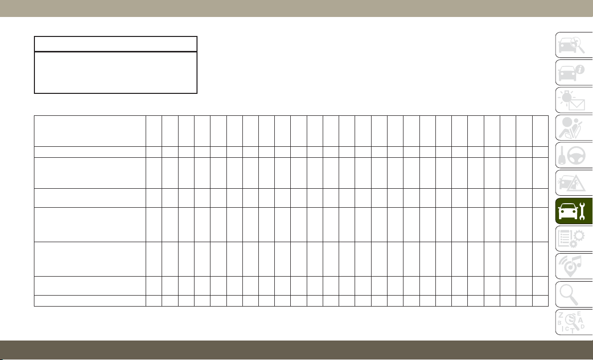
CAUTION!
Failure to perform the required mainte-
nance items may result in damage to the
vehicle.
Maintenance Plan
Miles:
6,000
12,000
18,000
24,000
30,000
36,000
42,000
48,000
54,000
60,000
66,000
72,000
78,000
84,000
90,000
96,000
102,000
108,000
114,000
120,000
126,000
132,000
138,000
144,000
150,000
Or Months: 6 12 18 24 30 36 42 48 54 60 66 72 78 84 90 96 102 108 114 120 126 132 138 144 150
Or Kilometers:
10,000
20,000
30,000
40,000
50,000
60,000
70,000
80,000
90,000
100,000
110,000
120,000
130,000
140,000
150,000
160,000
170,000
180,000
190,000
200,000
210,000
220,000
230,000
240,000
250,000
Change the engine oil and engine
oil filter.
XXXXXXXXXXXXXXXXXXXXXXXXX
Rotate the tires, rotate at the first
sign of irregular wear, even if it
occurs before scheduled mainte-
nance.
XXXXXXXXXXXXXXXXXXXXXXXXX
If using your vehicle for any of the
following: dusty or off-road condi-
tions. Inspect the engine air
cleaner filter; replace if necessary.
XXXXXXXXXXXX
Inspect the brake linings; replace
if necessary.
XXXXXXXXXXXX
Inspect the CV joints. X X X X X X X X X X X X
235

Miles:
6,000
12,000
18,000
24,000
30,000
36,000
42,000
48,000
54,000
60,000
66,000
72,000
78,000
84,000
90,000
96,000
102,000
108,000
114,000
120,000
126,000
132,000
138,000
144,000
150,000
Or Months: 6 12 18 24 30 36 42 48 54 60 66 72 78 84 90 96 102 108 114 120 126 132 138 144 150
Or Kilometers:
10,000
20,000
30,000
40,000
50,000
60,000
70,000
80,000
90,000
100,000
110,000
120,000
130,000
140,000
150,000
160,000
170,000
180,000
190,000
200,000
210,000
220,000
230,000
240,000
250,000
Inspect the exhaust system. X X X X X X X X X X X X
Adjust the parking brake on
vehicles equipped with four wheel
disc brakes.
XXXXX
Drain the transfer case and refill. X X X X X
Inspect the accessory drive belts
replace if necessary.
XX
Inspect the front and rear axle
fluid. Change if using your vehicle
for any of the following: police,
taxi, fleet, sustained high speed
driving, off-road or frequent trailer
towing.
XXXXXX
Inspect front suspension, tie rod
ends, and boot seals, for cracks or
leaks and all parts for damage,
wear, improper looseness or end
play; replace if necessary.
XXXXXXXXXXXX
Replace the engine air cleaner
filter.
XXXXX
Replace the air conditioning filter. X X X X X X
SERVICING AND MAINTENANCE
236
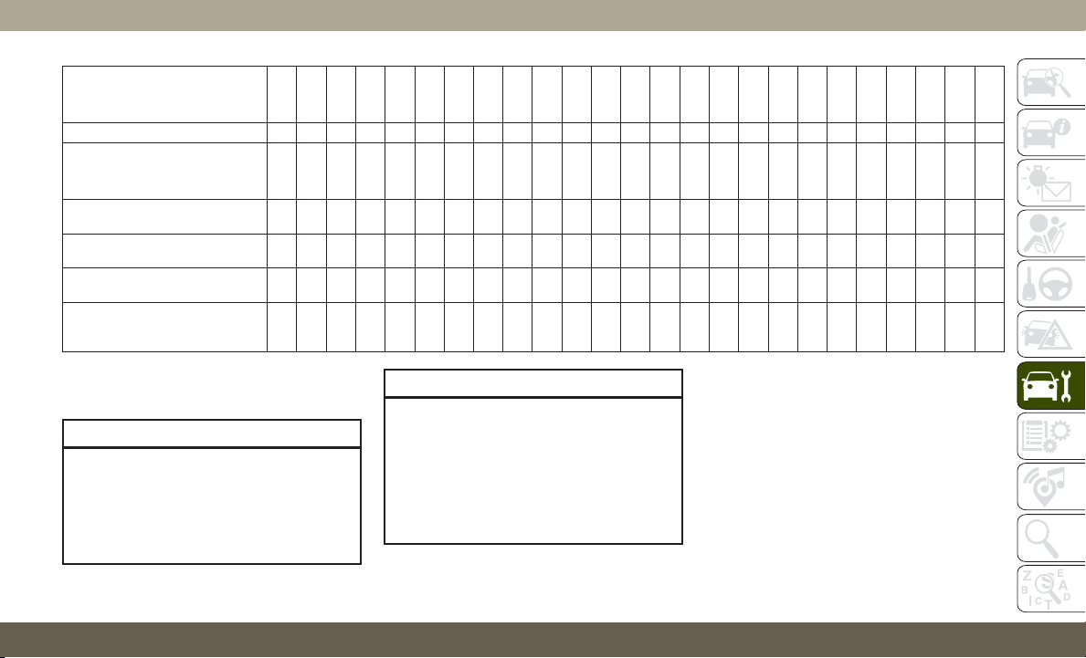
Miles:
6,000
12,000
18,000
24,000
30,000
36,000
42,000
48,000
54,000
60,000
66,000
72,000
78,000
84,000
90,000
96,000
102,000
108,000
114,000
120,000
126,000
132,000
138,000
144,000
150,000
Or Months: 6 12 18 24 30 36 42 48 54 60 66 72 78 84 90 96 102 108 114 120 126 132 138 144 150
Or Kilometers:
10,000
20,000
30,000
40,000
50,000
60,000
70,000
80,000
90,000
100,000
110,000
120,000
130,000
140,000
150,000
160,000
170,000
180,000
190,000
200,000
210,000
220,000
230,000
240,000
250,000
Inspect and replace the PCV Valve
if necessary
X
Replace the spark plugs – 6.2L
Supercharged Engine. **
XX
Replace the spark plugs – 6.4L
Engine. **
X
Flush and replace the engine cool-
ant at 120 months if not done at
150,000 miles (240,000 km).
XX
**
The spark plug change interval is mileage
based only, monthly intervals do not apply.
WARNING!
• You can be badly injured working on or
around a motor vehicle. Do only service
work for which you have the knowledge
and the right equipment. If you have any
doubt about your ability to perform a
WARNING!
service job, take your vehicle to a com-
petent mechanic.
• Failure to properly inspect and maintain
your vehicle could result in a component
malfunction and effect vehicle handling
and performance. This could cause an
accident.
237

Scheduled Servicing — Diesel Engine
Your vehicle is equipped with an automatic
oil change indicator system. The oil change
indicator system will remind you that it is
time to take your vehicle in for scheduled
maintenance.
Based on engine operation conditions, the oil
change indicator message will illuminate.
This means that service is required for your
vehicle. Operating conditions such as fre-
quent short-trips, trailer tow, extremely hot or
cold ambient temperatures will influence
when the “Oil Change Required” message is
displayed. Severe Operating Conditions
will cause the change oil message to illumi-
nate more frequently. Have your vehicle ser-
viced as soon as possible, within the next
500 miles (805 km).
Your authorized dealer will reset the oil
change indicator message after completing
the scheduled oil change. If a scheduled oil
change is performed by someone other than
your authorized dealer, the message can be
reset by referring to the steps described un-
der “Instrument Cluster Display” in “Getting
To Know Your Instrument Panel” for further
information.
NOTE:
Under no circumstances should oil change
intervals exceed 10,000 miles (16,000 km)
or twelve months, whichever comes first.
Engine Oil Filter Replacement
Residual oil in the housing may spill from the
housing when the new filter is installed if the
residual oil is not either removed from the
housing or enough time has not elapsed to
allow the oil to drain back into the engine.
When servicing the oil filter on this engine,
carefully remove the filter and use a suction
gun to remove any residual oil left in the
housing or wait about 30 minutes for the oil
to drain back into the engine.
Once A Month Or Before A Long Trip:
• Check engine oil level
• Check windshield washer fluid level
• Check the tire inflation pressures and look
for unusual wear or damage
• Check the fluid levels of the coolant reser-
voir, brake master cylinder, and fill as
needed
• Check function of all interior and exterior
lights
SERVICING AND MAINTENANCE
238

Maintenance Plan — Diesel Fuel Up To
B5 Biodiesel
Required Maintenance
Refer to the Maintenance Plans on the follow-
ing pages for required maintenance.
At Every Oil Change Interval As Indicated By Oil Change Indicator System:
•
Change oil and filter.
•
Completely fill the Diesel Exhaust Fluid tank.
•
Drain water from fuel filter assembly.
•
Rotate the tires. Rotate at the first sign of irregular wear, even if it occurs before the oil indicator system turns on.
•
Inspect battery and clean and tighten terminals as required.
•
Inspect brake pads, shoes, rotors, drums, hoses and park brake.
•
Inspect engine cooling system protection and hoses.
•
Inspect exhaust system.
•
Inspect engine air cleaner if using in dusty or off-road conditions.
At Every Second Oil Change Interval As Indicated By Oil Change Indicator System:
•
Change fuel filter.
239

Mileage or time passed (whichever comes first)
10,000
20,000
30,000
40,000
50,000
60,000
70,000
80,000
90,000
100,000
110,000
120,000
130,000
140,000
150,000
Or Years: 1 2 3 4 5 6 7 8 9 10 11 12 13 14 15
Or Kilometers:
16,000
32,000
48,000
64,000
80,000
96,000
112,000
128,000
144,000
160,000
176,000
192,000
208,000
224,000
240,000
Additional Inspections
Completely fill the Diesel Exhaust Fluid tank. X X X X X X X X X X X X X X X
Inspect the CV joints. X X X X X
Inspect front suspension, tie rod ends, and replace if necessary. X X X X X X X
Inspect the front and rear axle fluid, change if using your vehicle
for police, taxi, fleet, off-road or frequent trailer towing.
XXX X X X X
Inspect the brake linings, parking brake function. X X X X X X X
Inspect transfer case fluid. X X X X
Additional Maintenance
Drain water from fuel filter assembly. X X X X X X X X X X X X X X X
Replace fuel filters and drain water from the fuel filter assembly.
Fuel filter replacement intervals should be every second oil change and must not exceed
20,000 miles (32 000 km) if using diesel fuel up to B5.
Replace engine air filter. X X X X X
Replace the air conditioning filter. X X X X X X X
Flush and replace the engine coolant at 10 years or
150,000 miles (240,000 km) whichever comes first.
XX
Replace accessory drive belt(s). X
Change transfer case fluid. X
SERVICING AND MAINTENANCE
240
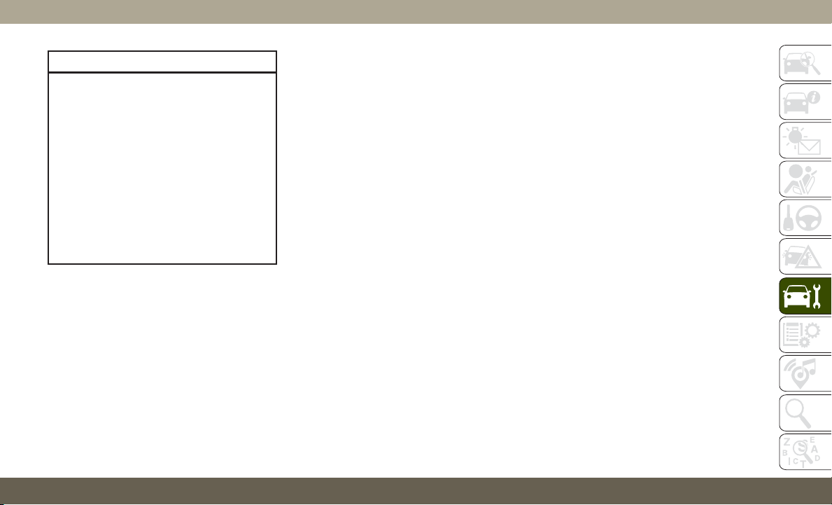
WARNING!
• You can be badly injured working on or
around a motor vehicle. Do only service
work for which you have the knowledge
and the right equipment. If you have any
doubt about your ability to perform a
service job, take your vehicle to a com-
petent mechanic.
• Failure to properly inspect and maintain
your vehicle could result in a component
malfunction and effect vehicle handling
and performance. This could cause an
accident.
Additional Maintenance — B6 To B20
Biodiesel
NOTE:
• Under no circumstances should oil change
intervals exceed 8,000 miles (12 875 km)
or six months, whichever comes first when
using Biodiesel blends greater than 5%
(B5).
• The owner is required to monitor mileage
for B6-B20 biodiesel, the automatic oil
change indicator system does not reflect
the use of biofuels.
• Fuel filter change interval is maintained at
every second oil change. This is especially
important with biodiesel usage.
241
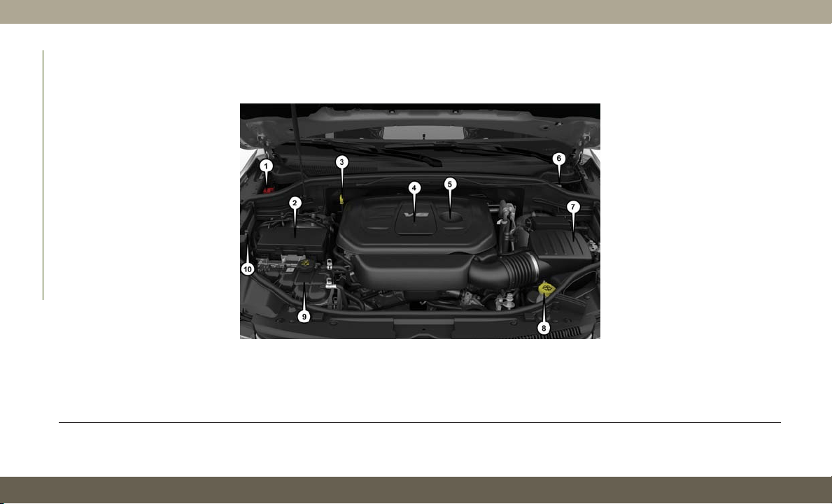
ENGINE COMPARTMENT
3.6L Engine
1 — Remote Jump Start Positive Terminal 6 — Brake Fluid Reservoir
2 — Power Distribution Center (Fuses) 7 — Air Cleaner Filter
3 — Engine Oil Dipstick 8 — Washer Fluid Reservoir
4 — Engine Oil Filter Access 9 — Engine Coolant Reservoir
5 — Engine Oil Fill 10 — Remote Jump Start Negative Terminal
SERVICING AND MAINTENANCE
242
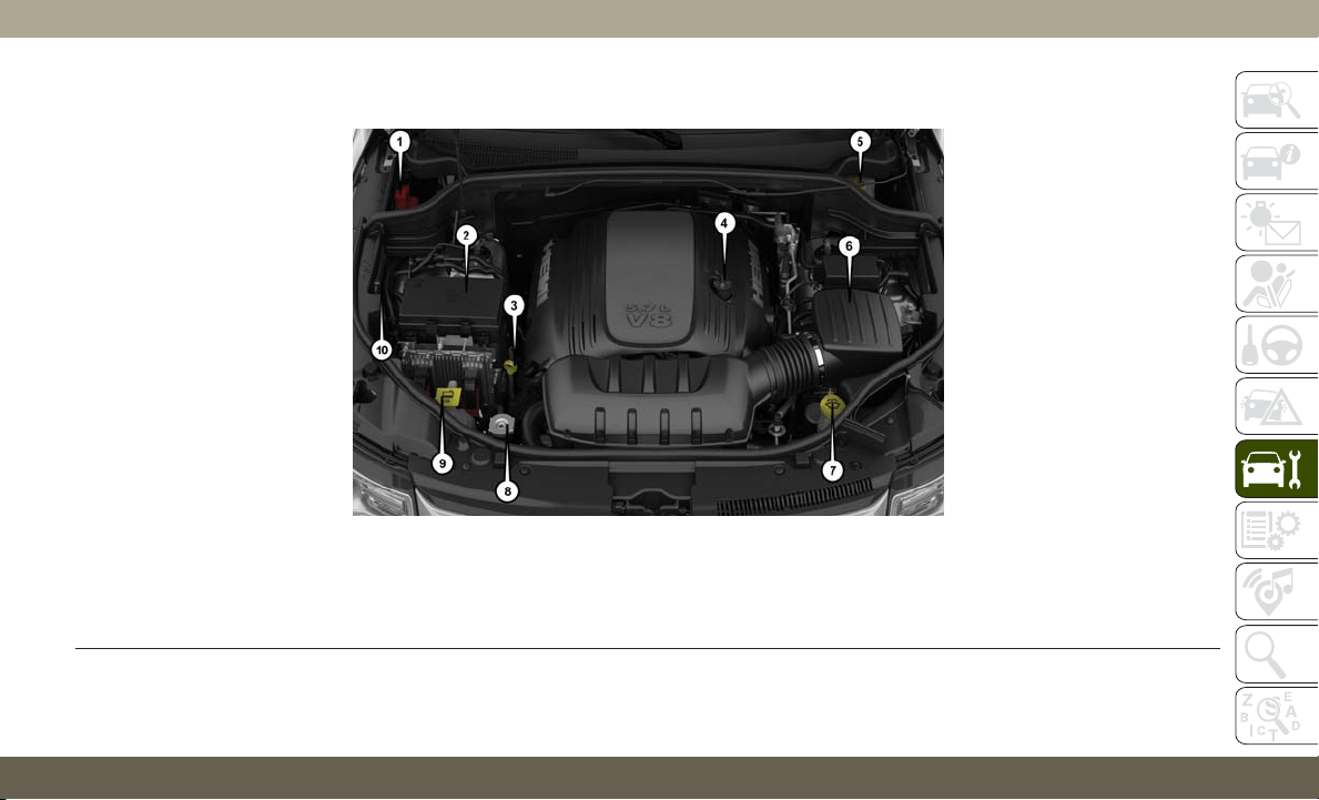
5.7L Engine
1 — Remote Jump Start Positive Terminal 6 — Air Cleaner Filter
2 — Power Distribution Center (Fuses) 7 — Washer Fluid Reservoir
3 — Engine Oil Dipstick 8 — Coolant Pressure Cap (Radiator)
4 — Engine Oil Fill 9 — Engine Coolant Reservoir
5 — Brake Fluid Reservoir 10 — Remote Jump Start Negative Terminal
243

6.2L Supercharged Engine
1 — Remote Jump Start Positive Terminal
2 — Power Distribution Center (Fuses)
3 — Intercooler Coolant Reservoir
4 — Engine Oil Fill
5 — Brake Fluid Reservoir
6 — Air Cleaner Filter
7 — Washer Fluid Reservoir
8 — Engine Oil Dipstick
9 — Coolant Pressure Cap (Radiator)
10 — Engine Coolant Reservoir
11 — Remote Jump Start Negative Terminal
SERVICING AND MAINTENANCE
244
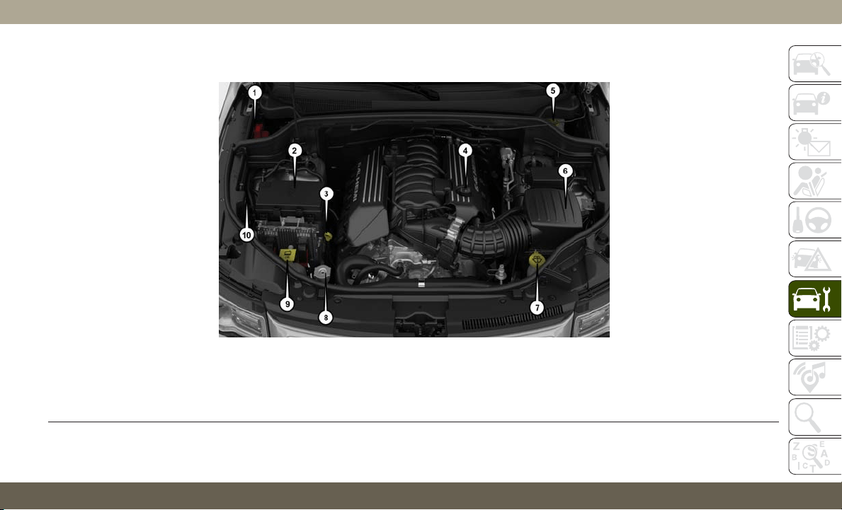
6.4L Engine
1 — Remote Jump Start Positive Terminal 6 — Air Cleaner Filter
2 — Power Distribution Center (Fuses) 7 — Washer Fluid Reservoir
3 — Engine Oil Dipstick 8 — Coolant Pressure Cap (Radiator)
4 — Engine Oil Fill 9 — Engine Coolant Reservoir
5 — Brake Fluid Reservoir 10 — Remote Jump Start Negative Terminal
245
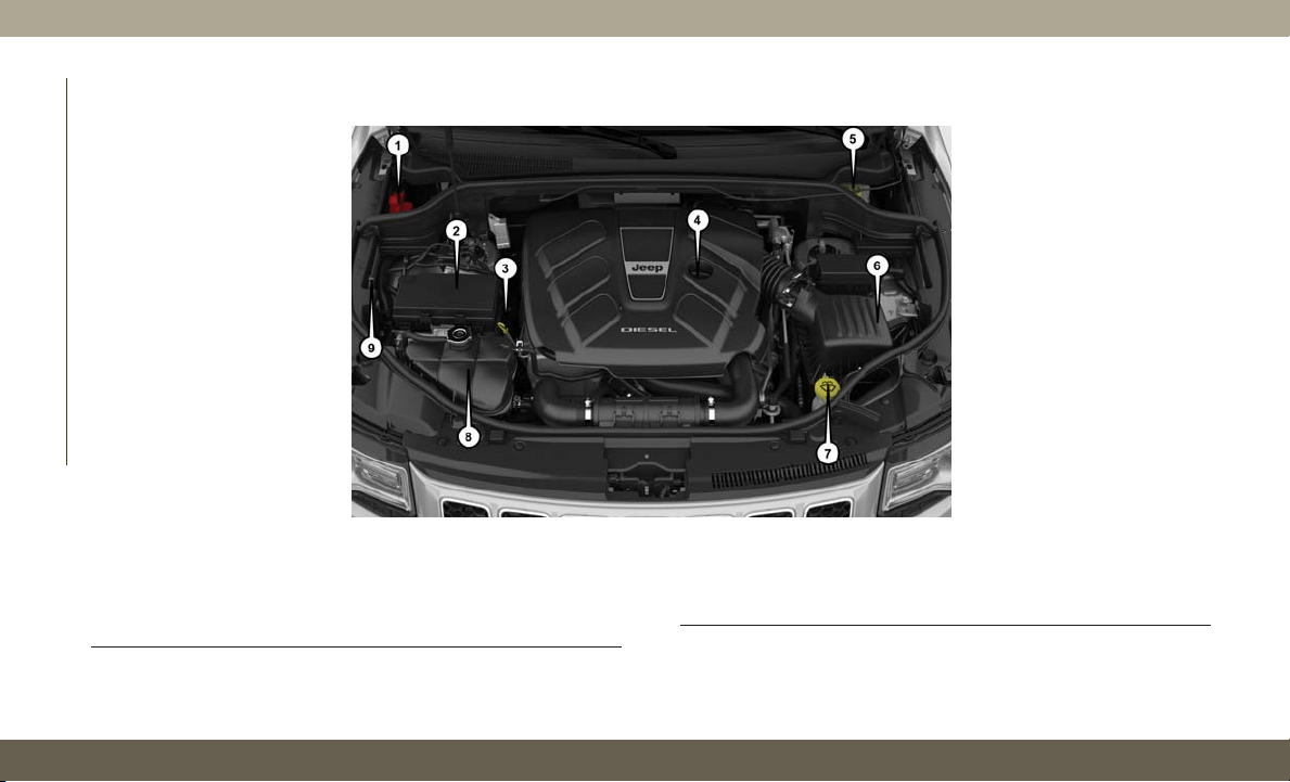
3.0L Diesel Engine
1 — Remote Jump Start Positive Terminal
2 — Power Distribution Center (Fuses)
3 — Engine Oil Dipstick
4 — Engine Oil Fill
5 — Brake Fluid Reservoir
6 — Air Cleaner Filter
7 — Washer Fluid Reservoir
8 — Coolant Pressure Reservoir
9 — Remote Jump Start Negative Terminal
SERVICING AND MAINTENANCE
246
Checking Oil Level — Gasoline Engine
To assure proper lubrication of your vehicle’s
engine, the engine oil must be maintained at
the correct level. Check the oil level at regular
intervals, such as every fuel stop. The best
time to check the engine oil level is about five
minutes after a fully warmed up engine is
shut off.
Checking the oil while the vehicle is on level
ground will improve the accuracy of the oil
level readings. Always maintain the oil level
within the SAFE zone on the dipstick. Adding
one quart of oil when the reading is at the
bottom of the SAFE zone will result in a
reading at the top of the safe zone on these
engines.
CAUTION!
Overfilling or underfilling the crankcase
will cause aeration or loss of oil pressure.
This could damage your engine.
Checking Oil Level — 3.0 Diesel Engine
To assure proper lubrication of your vehicle's
engine, the engine oil must be maintained at
the correct level. Check the oil level at regular
intervals. The best time to check the oil level
is before starting the engine after it has been
parked overnight. When checking oil after
operating the engine, first ensure the engine
is at full operating temperature, then wait for
five minutes after engine shutdown to check
the oil.
Checking the oil while the vehicle is on level
ground will improve the accuracy of the oil
level readings. Add oil only when the level on
the dipstick is below the “MIN” mark. The
total capacity from the MIN mark to the MAX
mark is 1 qt (1 L).
CAUTION!
Overfilling or underfilling the crankcase
will cause oil aeration or loss of oil pres-
sure. This could damage your engine.
NOTE:
I
t is possible for your oil level to be slightly
higher than a previous check. This would be
due to diesel fuel that may temporarily be in
the crankcase due to operation of the diesel
particulate filter regeneration strategy. This
fuel will evaporate out under normal operation.
Never operate the engine with oil level below
the “MIN” mark or above the upper “MAX”
mark.
Adding Washer Fluid
The instrument cluster display will indicate
when the washer fluid level is low. When the
sensor detects a low fluid level, the wind-
shield will light on the vehicle graphic outline
and the “WASHER FLUID LOW” message
will be displayed.
The fluid reservoir for the windshield washers
and the rear window washer is shared. The
fluid reservoir is located in the engine com-
partment, be sure to check the fluid level at
regular intervals. Fill the reservoir with wind-
shield washer solvent only (not radiator anti-
247

freeze). When refilling the washer fluid reser-
voir, take some washer fluid and apply it to a
cloth or towel and wipe clean the wiper
blades, this will help blade performance. To
prevent freeze-up of your windshield washer
system in cold weather, select a solution or
mixture that meets or exceeds the tempera-
ture range of your climate. This rating infor-
mation can be found on most washer fluid
containers.
WARNING!
Commercially available windshield washer
solvents are flammable. They could ignite
and burn you. Care must be exercised
when filling or working around the washer
solution.
Maintenance-Free Battery
Your vehicle is equipped with a maintenance-
free battery. You will never have to add water,
nor is periodic maintenance required.
WARNING!
• Battery fluid is a corrosive acid solution
and can burn or even blind you. Do not
allow battery fluid to contact your eyes,
skin, or clothing. Do not lean over a
battery when attaching clamps. If acid
splashes in eyes or on skin, flush the
area immediately with large amounts of
water. Refer to “Jump Starting Proce-
dure” in “In Case Of Emergency” for
further information.
• Battery gas is flammable and explosive.
Keep flame or sparks away from the
battery. Do not use a booster battery or
any other booster source with an output
greater than 12 Volts. Do not allow cable
clamps to touch each other.
• Battery posts, terminals, and related ac-
cessories contain lead and lead com-
pounds. Wash hands after handling.
CAUTION!
• It is essential when replacing the cables
on the battery that the positive cable is
attached to the positive post and the
negative cable is attached to the nega-
tive post. Battery posts are marked posi-
tive (+) and negative (-) and are identi-
fied on the battery case. Cable clamps
should be tight on the terminal posts
and free of corrosion.
•If
a “fast charger” is used while the bat-
tery is in the vehicle, disconnect both
vehicle battery cables before connecting
the charger to the battery. Do not use a
“fast charger” to provide starting voltage.
SERVICING AND MAINTENANCE
248
DEALER SERVICE
An authorized dealer has the qualified service
personnel, special tools, and equipment to
perform all service operations in an expert
manner. Service Manuals are available which
include detailed service information for your
vehicle. Refer to these Service Manuals be-
fore attempting any procedure yourself.
NOTE:
I
ntentional tampering with emissions control
systems may void your warranty and could
result in civil penalties being assessed against
you.
WARNING!
You can be badly injured working on or
around a motor vehicle. Only do service
work for which you have the knowledge
and the proper equipment. If you have any
doubt about your ability to perform a ser-
vice job, take your vehicle to a competent
mechanic.
Air Conditioner Maintenance
For best possible performance, your air con-
ditioner should be checked and serviced by
an authorized dealer at the start of each warm
season. This service should include cleaning
of the condenser fins and a performance test.
Drive belt tension should also be checked at
this time.
WARNING!
• Use only refrigerants and compressor
lubricants approved by the manufac-
turer for your air conditioning system.
Some unapproved refrigerants are flam-
mable and can explode, injuring you.
Other unapproved refrigerants or lubri-
cants can cause the system to fail, re-
quiring costly repairs. Refer to Warranty
Information Book, for further warranty
information.
WARNING!
•T
he air conditioning system contains re-
frigerant under high pressure. To avoid
risk of personal injury or damage to the
system, adding refrigerant or any repair
requiring lines to be disconnected should
be done by an experienced technician.
CAUTION!
Do not use chemical flushes in your air
conditioning system as the chemicals can
damage your air conditioning components.
Such damage is not covered by the New
Vehicle Limited Warranty.
249
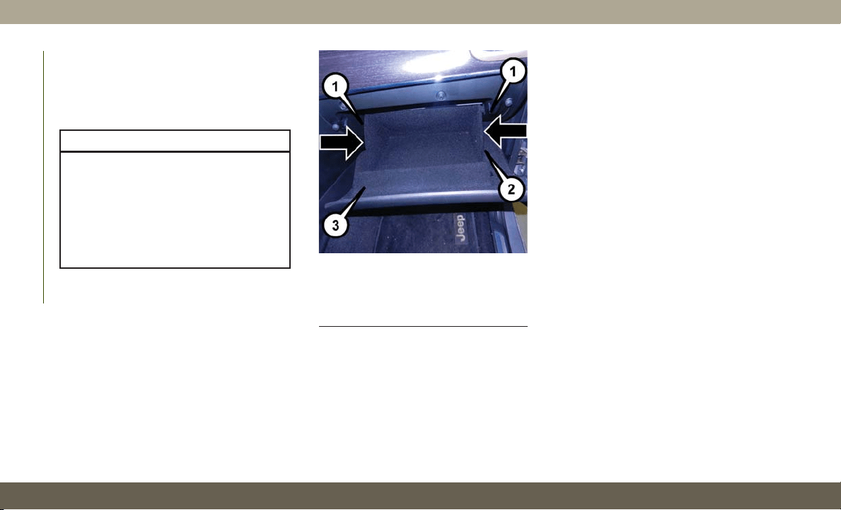
Air Conditioning Filter Replacement
(A/C Air Filter)
Refer to “Scheduled Servicing” in this sec-
tion for the proper maintenance intervals.
WARNING!
Do not remove the cabin air filter while the
vehicle is running, or while the ignition is
in the ACC or ON/RUN mode. With the
cabin air filter removed and the blower
operating, the blower can contact hands
and may propel dirt and debris into your
eyes, resulting in personal injury.
The A/C air filter is located in the fresh air
inlet behind the glove compartment. Perform
the following procedure to replace the filter:
1. Open the glove compartment and remove
all contents.
2. There are glove compartment travel stops
on both sides of the glove compartment
door, partially close the glove compart-
ment door and push inward to release the
glove compartment travel stop on one side
and repeat this procedure for the opposite
side.
3. Pull the right hand side of the glove com-
partment door toward the rear of the ve-
hicle to disengage the glove compartment
door from its hinges.
NOTE:
When disengaging the glove compartment
door from its hinges, there will be some
resistance.
4. With the glove compartment door loose,
remove the glove compartment tension
tether and tether clip by sliding the clip
toward the face of the glove compartment
door and lifting the clip out of glove com-
partment door.
5. Remove the filter cover by disengaging
the retaining tab and mid way snap that
secures the filter cover to the HVAC hous-
ing. Disengage the mid way snap by pull-
ing the door outward. Unhinge the filter
cover on the right side to fully remove the
cover.
Glove Compartment
1 — Glove Compartment Travel Stops
2 — Glove Compartment Tension Tether
3 — Glove Compartment Door
SERVICING AND MAINTENANCE
250
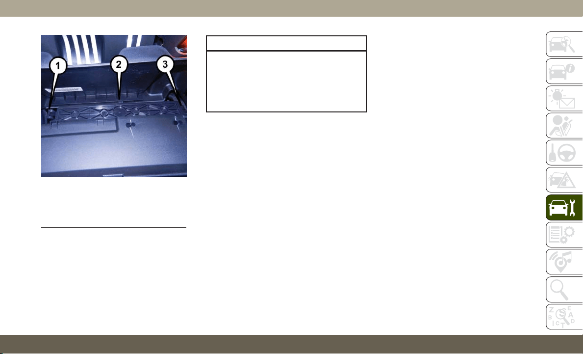
6. Remove the A/C air filter by pulling it
straight out of the housing.
7. Install the A/C air filter with the arrow on
the filter pointing toward the floor. When
installing the filter cover, make sure the
retaining tabs fully engage the cover.
CAUTION!
The cabin air filter is identified with an
arrow to indicate airflow direction through
the filter. Failure to properly install the
filter will result in the need to replace it
more often.
8. Reinstall the glove compartment door on
the door hinge and reattach the tension
tether by inserting the tether clip in the
glove compartment and sliding the clip
away from the face of the glove compart-
ment door.
9. Push the door to the near closed position
to reengage the glove compartment travel
stops.
NOTE:
Ensure the glove compartment door
hinges and glove compartment travel
stops are fully engaged.
Windshield Wiper Blades
Clean the rubber edges of the wiper blades
and the windshield periodically with a sponge
or soft cloth and a mild nonabrasive cleaner.
This will remove accumulations of salt or road
film.
Operation of the wipers on dry glass for long
periods may cause deterioration of the wiper
blades. Always use washer fluid when using
the wipers to remove salt or dirt from a dry
windshield.
Avoid using the wiper blades to remove frost
or ice from the windshield. Keep the blade
rubber out of contact with petroleum prod-
ucts such as engine oil, gasoline, etc.
NOTE:
Life expectancy of wiper blades varies de-
pending on geographical area and frequency
of use. Poor performance of blades may be
present with chattering, marks, water lines or
wet spots. If any of these conditions are
present, clean the wiper blades or replace as
necessary.
A/C Air Filter Cover
1 — Retaining Tab
2 — Mid Way Snap
3 — Filter Cover Hinge
251
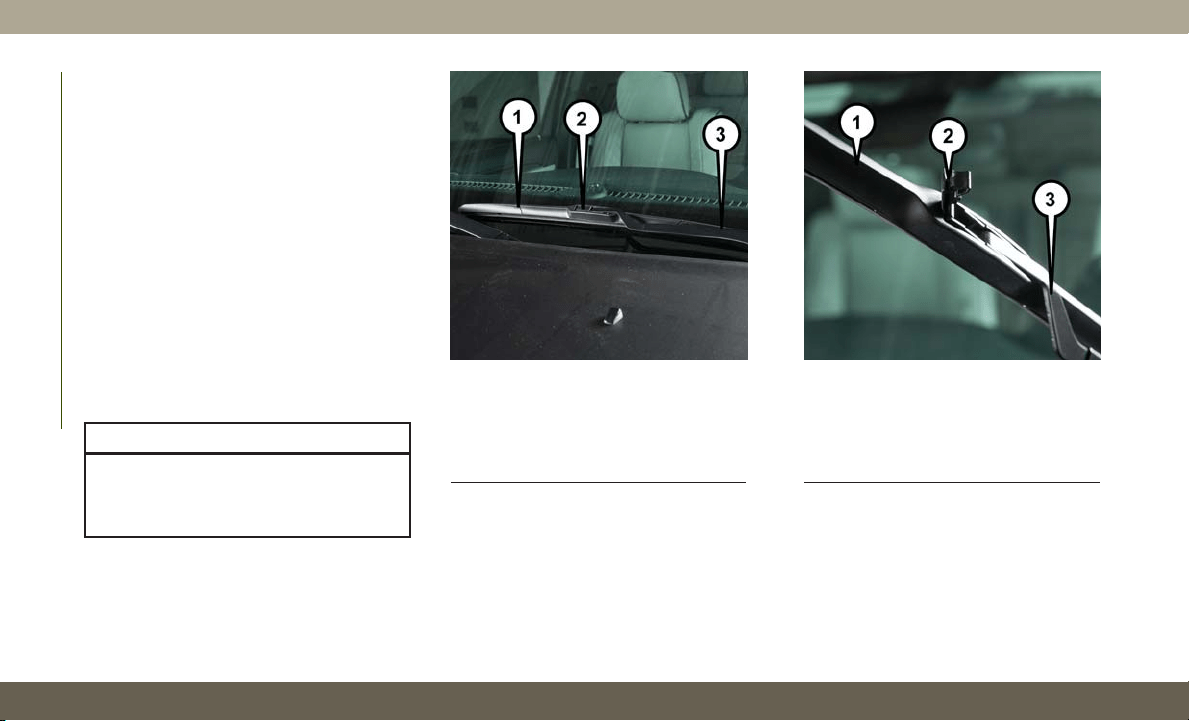
T
he wiper blades and wiper arms should be
inspected periodically, not just when wiper
performance problems are experienced. This
inspection should include the following points:
• Wear or uneven edges
• Foreign material
• Hardening or cracking
• Deformation or fatigue
If a wiper blade or wiper arm is damaged,
replace the affected wiper arm or blade with
a new unit. Do not attempt to repair a wiper
arm or blade that is damaged.
Front Wiper Blade Removal/Installation
CAUTION!
Do not allow the wiper arm to spring back
against the glass without the wiper blade
in place or the glass may be damaged.
1. Lift the wiper arm to raise the wiper blade
off of the glass, until the wiper arm is in
the full up position.
2. To disengage the wiper blade from the
wiper arm, flip up the release tab on the
wiper blade and while holding the wiper
arm with one hand, slide the wiper blade
down towards the base of the wiper arm.
3. With the wiper blade disengaged, remove
the wiper blade from the wiper arm by
holding the wiper arm with one hand and
separating the wiper blade from the wiper
Wiper Blade With Release Tab In Locked
Position
1 — Wiper
2 — Release Tab
3 — Wiper Arm
Wiper Blade With Release Tab In
Unlocked Position
1 — Wiper Blade
2 — Release Tab
3 — Wiper Arm
SERVICING AND MAINTENANCE
252
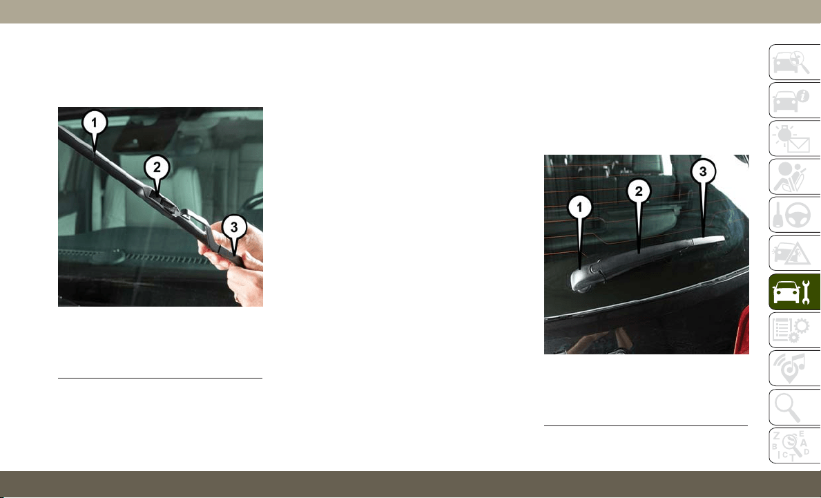
arm with the other hand (move the wiper
blade toward the right side of the vehicle
to separate the wiper blade from the wiper
arm).
4. Gently lower the wiper arm onto the glass.
Installing The Front Wipers
1. Lift the wiper arm off of the glass, until
the wiper arm is in the full up position.
2. P
osition the wiper blade near the hook on the
tip of the wiper arm with the wiper release
tab open and the blade side of the wiper
facing up and away from the windshield.
3. Insert the hook on the tip of the arm
through the opening in the wiper blade
under the release tab.
4. Slide the wiper blade up into the hook on
the wiper arm and rotate the wiper blade
until it is flush against the wiper arm. Fold
down the latch release tab and snap it into
its locked position. Latch engagement will
be accompanied by an audible click.
5. Gently lower the wiper blade onto the
glass.
Rear Wiper Blade Removal/Installation
1. Lift the rear wiper arm pivot cap away
from the glass to allow the rear wiper
blade to be raised off of the glass.
NOTE:
The rear wiper arm cannot be fully raised
off the glass unless the wiper arm pivot
cap is unsnapped first. Attempting to fully
raise the rear wiper arm without unsnap-
ping the wiper arm pivot cap may damage
the vehicle.
Wiper Blade Removed From Wiper Arm
1 — Wiper Blade
2 — Release Tab
3 — Wiper Arm
Rear Wiper
1 — Wiper Arm Pivot Cap
2 — Wiper Arm
3 — Wiper Blade
253
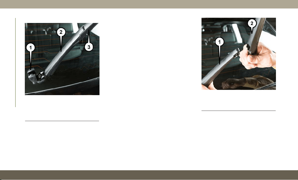
2. Lift the rear wiper arm fully off the glass. 3. To remove the wiper blade from the wiper
arm, grasp the bottom end of the wiper
blade nearest to wiper arm with your right
hand. With your left hand hold the wiper
arm as you pull the wiper blade away from
the wiper arm past its stop far enough to
unsnap the wiper blade pivot pin from the
receptacle on the end of the wiper arm.
NOTE:
Resistance will be accompanied by an
audible snap.
4. Still grasping the bottom end of the wiper
blade, move the wiper blade upward and
away from the wiper arm to disengage.
5. Gently lower the tip of the wiper arm onto
the glass.
Wiper Blade In Folded Out Position
1 — Wiper Arm Pivot Cap
2 — Wiper Arm
3 — Wiper Blade
Wiper Blade Removed From Wiper Arm
1 — Wiper Arm
2 — Wiper Blade
SERVICING AND MAINTENANCE
254
Installing The Rear Wiper
1. Lift the rear wiper arm pivot cap away
from the glass to allow the rear wiper
blade to be raised off of the glass.
NOTE:
The rear wiper arm cannot be fully raised
off the glass unless the wiper arm pivot
cap is unsnapped first. Attempting to fully
raise the rear wiper arm without unsnap-
ping the wiper arm pivot cap may damage
the vehicle.
2. Lift the rear wiper arm fully off the glass.
3. Insert the wiper blade pivot pin into the
opening on the end of the wiper arm. Grab
the bottom end of the wiper arm with one
hand, and press the wiper blade flush with
the wiper arm until it snaps into place.
4. Lower the wiper blade onto the glass and
snap the wiper arm pivot cap back into
place.
Cooling System
WARNING!
• You or others can be badly burned by hot
engine coolant (antifreeze) or steam
from your radiator. If you see or hear
steam coming from under the hood, do
not open the hood until the radiator has
had time to cool. Never open a cooling
system pressure cap when the radiator or
coolant bottle is hot.
• Keep hands, tools, clothing, and jewelry
away from the radiator cooling fan when
the hood is raised. The fan starts auto-
matically and may start at any time,
whether the engine is running or not.
• When working near the radiator cooling
fan, disconnect the fan motor lead or
turn the ignition to the OFF mode. The
fan is temperature controlled and can
start at any time the ignition is in the ON
mode.
Engine Coolant Checks
Check the engine coolant (antifreeze) protec-
tion every 12 months (before the onset of
freezing weather, where applicable). If the
engine coolant (antifreeze) is dirty, the sys-
tem should be drained, flushed, and refilled
with fresh OAT coolant (conforming to
MS.90032) by an authorized dealer. Check
the front of the A/C condenser for any accu-
mulation of bugs, leaves, etc. If dirty, clean
by gently spraying water from a garden hose
vertically down the face of the condenser.
Check the engine cooling system hoses for
brittle rubber, cracking, tears, cuts, and
tightness of the connection at the coolant
recovery bottle and radiator. Inspect the en-
tire system for leaks. DO NOT REMOVE THE
COOLANT PRESSURE CAP WHEN THE
COOLING SYSTEM IS HOT.
255

Brake System
In order to assure brake system performance,
all brake system components should be in-
spected periodically. Refer to the “Mainte-
nance Plan” in this section for the proper
maintenance intervals.
WARNING!
Riding the brakes can lead to brake failure
and possibly a collision. Driving with your
foot resting or riding on the brake pedal
can result in abnormally high brake tem-
peratures, excessive lining wear, and pos-
sible brake damage. You would not have
your full braking capacity in an emergency.
Fluid Level Check — Brake Master Cylinder
The fluid level of the master cylinder should
be checked whenever the vehicle is serviced,
or immediately if the brake system warning
light is on. If necessary, add fluid to bring
level within the designated marks on the side
of the reservoir of the brake master cylinder.
Be sure to clean the top of the master cylin-
der area before removing cap. With disc
brakes, fluid level can be expected to fall as
the brake pads wear. Brake fluid level should
be checked when pads are replaced. If the
brake fluid is abnormally low, check the sys-
tem for leaks.
Refer to “Fluids And Lubricants” in “Techni-
cal Specifications” for further information.
WARNING!
• Use only manufacturer's recommended
brake fluid. Refer to “Fluids And Lubri-
cants” in “Technical Specifications” for
further information. Using the wrong
type of brake fluid can severely damage
your brake system and/or impair its per-
formance. The proper type of brake fluid
for your vehicle is also identified on the
original factory installed hydraulic mas-
ter cylinder reservoir.
• To avoid contamination from foreign
matter or moisture, use only new brake
fluid or fluid that has been in a tightly
WARNING!
closed container. Keep the master cylin-
der reservoir cap secured at all times.
Brake fluid in a open container absorbs
moisture from the air resulting in a lower
boiling point. This may cause it to boil
unexpectedly during hard or prolonged
braking, resulting in sudden brake fail-
ure. This could result in a collision.
• Overfilling the brake fluid reservoir can
result in spilling brake fluid on hot en-
gine parts, causing the brake fluid to
catch fire. Brake fluid can also damage
painted and vinyl surfaces, care should
be taken to avoid its contact with these
surfaces.
• Do not allow petroleum based fluid to
contaminate the brake fluid. Brake seal
components could be damaged, causing
partial or complete brake failure. This
could result in a collision.
SERVICING AND MAINTENANCE
256
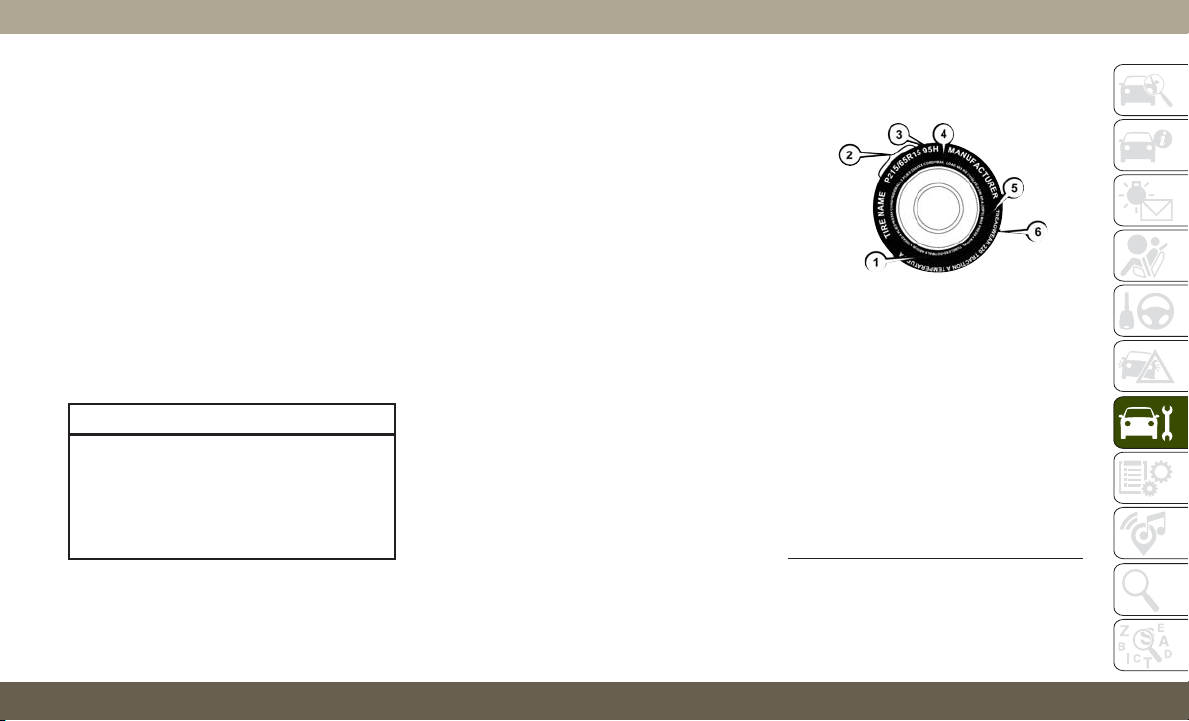
Automatic Transmission
Fluid Level Check
The fluid level is preset at the factory and
does not require adjustment under normal
operating conditions. Routine fluid level
checks are not required; therefore the trans-
mission has no dipstick. An authorized dealer
can check your transmission fluid level using
special service tools. If you notice fluid leak-
age or transmission malfunction, visit an au-
thorized dealer immediately to have the
transmission fluid level checked. Operating
the vehicle with an improper fluid level can
cause severe transmission damage.
CAUTION!
If a transmission fluid leak occurs, visit an
authorized dealer immediately. Severe
transmission damage may occur. An au-
thorized dealer has the proper tools to
adjust the fluid level accurately.
RAISING THE VEHICLE
In the case where it is necessary to raise the
vehicle, go to an authorized dealer or service
station.
TIRES
Tire Safety Information
Tire safety information will cover aspects of
the following information: Tire Markings, Tire
Identification Numbers, Tire Terminology and
Definitions, Tire Pressures, and Tire Loading.
Tire Markings
Tire Markings
1 — U.S. DOT
Safety Stan-
dards Code
(TIN)
4 — Maximum
Load
2 — Size
Designation
5 — Maximum
Pressure
3 — Service
Description
6 — Treadwear,
Traction and
Temperature
Grades
257

NOTE:
• P (Passenger) — Metric tire sizing is based
on U.S. design standards. P-Metric tires
have the letter “P” molded into the sidewall
preceding the size designation. Example:
P215/65R15 95H.
• European — Metric tire sizing is based on
European design standards. Tires designed
to this standard have the tire size molded
into the sidewall beginning with the sec-
tion width. The letter "P" is absent from
this tire size designation. Example: 215/
65R15 96H.
• LT (Light Truck) — Metric tire sizing is
based on U.S. design standards. The size
designation for LT-Metric tires is the same
as for P-Metric tires except for the letters
“LT” that are molded into the sidewall
preceding the size designation. Example:
LT235/85R16.
• Temporary spare tires are designed for tem-
porary emergency use only. Temporary high
pressure compact spare tires have the letter
“T” or “S” molded into the sidewall preced-
ing the size designation. Example: T145/
80D18 103M.
• High flotation tire sizing is based on U.S.
design standards and it begins with the
tire diameter molded into the sidewall.
Example: 31x10.5 R15 LT.
Tire Sizing Chart
EXAMPLE:
Example Size Designation: P215/65R15XL 95H, 215/65R15 96H, LT235/85R16C, T145/80D18 103M, 31x10.5 R15 LT
P = Passenger car tire size based on U.S. design standards, or
"....blank...." = Passenger car tire based on European design standards, or
LT = Light truck tire based on U.S. design standards, or
TorS= Temporary spare tire or
31 = Overall diameter in inches (in)
215, 235, 145 = Section width in millimeters (mm)
SERVICING AND MAINTENANCE
258
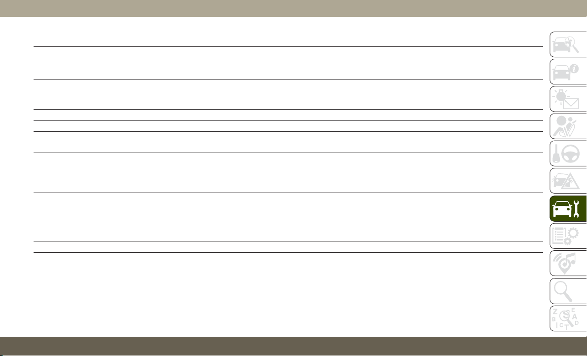
EXAMPLE:
65, 85, 80 = Aspect ratio in percent (%)
•
Ratio of section height to section width of tire, or
10.5 = Section width in inches (in)
R = Construction code
•
"R" means radial construction, or
• "D" means diagonal or bias construction
15, 16, 18 = Rim diameter in inches (in)
Service Description:
95 = Load Index
•
A numerical code associated with the maximum load a tire can carry
H = Speed Symbol
•
A symbol indicating the range of speeds at which a tire can carry a load corresponding to its load index under certain operating conditions
• The maximum speed corresponding to the speed symbol should only be achieved under specified operating conditions (i.e., tire pressure, vehicle
loading, road conditions, and posted speed limits)
Load Identification:
Absence of the following load identification symbols on the sidewall of the tire indicates a Standard Load (SL) tire:
•
XL = Extra load (or reinforced) tire, or
• LL = Light load tire or
• C, D, E, F, G = Load range associated with the maximum load a tire can carry at a specified pressure
Maximum Load – Maximum load indicates the maximum load this tire is designed to carry
Maximum Pressure – Maximum pressure indicates the maximum permissible cold tire inflation pressure for this tire
259

Tire Identification Number (TIN)
The TIN may be found on one or both sides of
the tire; however, the date code may only be
on one side. Tires with white sidewalls will
have the full TIN, including the date code,
located on the white sidewall side of the tire.
Look for the TIN on the outboard side of black
sidewall tires as mounted on the vehicle.
If the TIN is not found on the outboard side,
then you will find it on the inboard side of the
tire.
EXAMPLE:
DOT MA L9 ABCD 0301
DOT = Department of Transportation
• This symbol certifies that the tire is in compliance with the U.S. Department of Transportation tire safety standards and is approved for highway
use
MA = Code representing the tire manufacturing location (two digits)
L9 = Code representing the tire size (two digits)
ABCD = Code used by the tire manufacturer (one to four digits)
03 = Number representing the week in which the tire was manufactured (two digits)
•
03 means the 3rd week
01 = Number representing the year in which the tire was manufactured (two digits)
•
01 means the year 2001
• Prior to July 2000, tire manufacturers were only required to have one number to represent the year in which the tire was manufactured. Example:
031 could represent the 3rd week of 1981 or 1991
SERVICING AND MAINTENANCE
260

Tire Terminology And Definitions
Term Definition
B-Pillar
The vehicle B-Pillar is the structural member of the body located behind the front
door.
Cold Tire Inflation Pressure
Cold tire inflation pressure is defined as the tire pressure after the vehicle has not
been driven for at least three hours, or driven less than 1 mile (1.6 km) after sitting
for a minimum of three hours. Inflation pressure is measured in units of PSI (pounds
per square inch) or kPa (kilopascals).
Maximum Inflation Pressure
The maximum inflation pressure is the maximum permissible cold tire inflation pres-
sure for this tire. The maximum inflation pressure is molded into the sidewall.
Recommended Cold Tire Inflation Pressure
Vehicle manufacturer's recommended cold tire inflation pressure as shown on the tire
placard.
Tire Placard
A label permanently attached to the vehicle describing the vehicle’s loading capacity,
the original equipment tire sizes and the recommended cold tire inflation pressures.
261
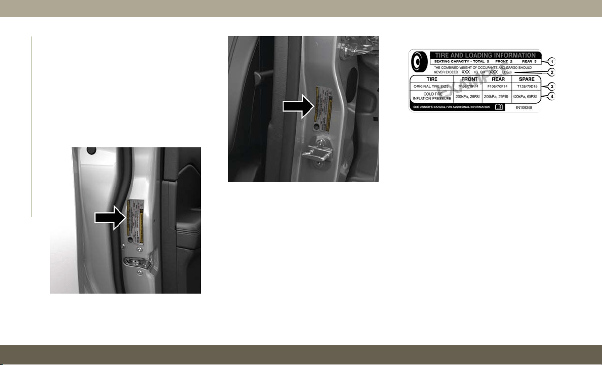
Tire Loading And Tire Pressure
NOTE:
The proper cold tire inflation pressure is
listed on the driver’s side B-Pillar or the rear
edge of the driver's side door.
Check the inflation pressure of each tire,
including the spare tire (if equipped), at least
monthly and inflate to the recommended
pressure for your vehicle.
Tire And Loading Information Placard
This placard tells you important information
about the:
1. Number of people that can be carried in
the vehicle.
2. Total weight your vehicle can carry.
3. Tire size designed for your vehicle.
4. Cold tire inflation pressures for the front,
rear, and spare tires.
Example Tire Placard Location (Door)
Example Tire Placard Location (B-Pillar)
Tire And Loading Information Placard
SERVICING AND MAINTENANCE
262
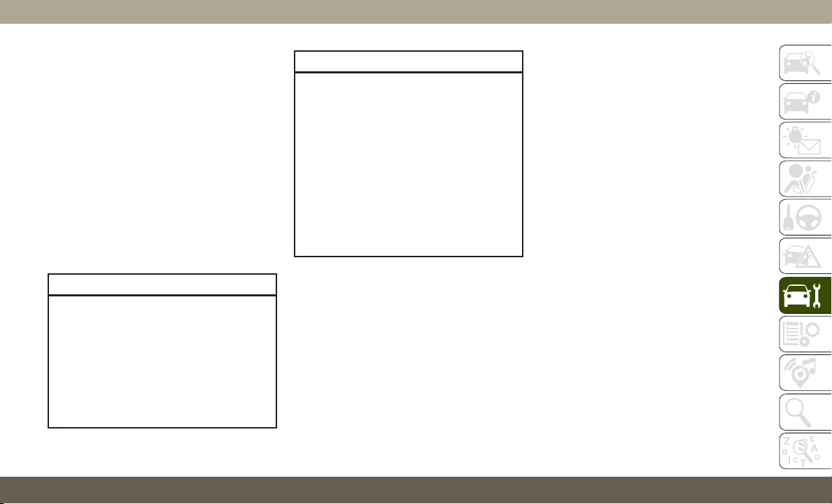
Tires — General Information
Tire Pressure
Proper tire inflation pressure is essential to
the safe and satisfactory operation of your
vehicle. Four primary areas are affected by
improper tire pressure:
• Safety and Vehicle Stability
• Economy
• Tread Wear
• Ride Comfort
Safety
WARNING!
• Improperly inflated tires are dangerous
and can cause collisions.
• Underinflation increases tire flexing and
can result in overheating and tire failure.
• Overinflation reduces a tire's ability to
cushion shock. Objects on the road and
chuckholes can cause damage that re-
sult in tire failure.
WARNING!
• Overinflated or underinflated tires can
affect vehicle handling and can fail sud-
denly, resulting in loss of vehicle control.
• Unequal tire pressures can cause steer-
ing problems. You could lose control of
your vehicle.
• Unequal tire pressures from one side of
the vehicle to the other can cause the
vehicle to drift to the right or left.
• Always drive with each tire inflated to
the recommended cold tire inflation
pressure.
Both under-inflation and over-inflation affect
the stability of the vehicle and can produce a
feeling of sluggish response or over respon-
siveness in the steering.
NOTE:
• Unequal tire pressures from side to side
may cause erratic and unpredictable steer-
ing response.
• Unequal tire pressure from side to side may
cause the vehicle to drift left or right.
Fuel Economy
Underinflated tires will increase tire rolling
resistance resulting in higher fuel consump-
tion.
Tread Wear
Improper cold tire inflation pressures can
cause abnormal wear patterns and reduced
tread life, resulting in the need for earlier tire
replacement.
Ride Comfort And Vehicle Stability
Proper tire inflation contributes to a comfort-
able ride. Over-inflation produces a jarring
and uncomfortable ride.
Tire Inflation Pressures
The proper cold tire inflation pressure is
listed on the driver's side B-Pillar or rear edge
of the driver's side door.
263

At least once a month:
• Check and adjust tire pressure with a good
quality pocket-type pressure gauge. Do not
make a visual judgement when determining
proper inflation. Tires may look properly
inflated even when they are under-inflated.
• Inspect tires for signs of tire wear or visible
damage.
CAUTION!
After inspecting or adjusting the tire pres-
sure, always reinstall the valve stem cap.
This will prevent moisture and dirt from
entering the valve stem, which could dam-
age the valve stem.
Inflation pressures specified on the placard
are always “cold tire inflation pressure”. Cold
tire inflation pressure is defined as the tire
pressure after the vehicle has not been driven
for at least three hours, or driven less than
1 mile (1.6 km) after sitting for a minimum of
three hours. The cold tire inflation pressure
must not exceed the maximum inflation pres-
sure molded into the tire sidewall.
Check tire pressures more often if subject to
a wide range of outdoor temperatures, as tire
pressures vary with temperature changes.
Tire pressures change by approximately 1 psi
(7 kPa) per 12°F (7°C) of air temperature
change. Keep this in mind when checking
tire pressure inside a garage, especially in the
Winter.
Example: If garage temperature = 68°F
(20°C) and the outside temperature = 32°F
(0°C) then the cold tire inflation pressure
should be increased by 3 psi (21 kPa), which
equals 1 psi (7 kPa) for every 12°F (7°C) for
this outside temperature condition.
Tire pressure may increase from 2 to 6 psi
(13 to 40 kPa) during operation. DO NOT
reduce this normal pressure build up or your
tire pressure will be too low.
Tire Pressures For High Speed Operation
The manufacturer advocates driving at safe
speeds and within posted speed limits.
Where speed limits or conditions are such
that the vehicle can be driven at high speeds,
maintaining correct tire inflation pressure is
very important. Increased tire pressure and
reduced vehicle loading may be required for
high-speed vehicle operation. Refer to an
authorized tire dealer or original equipment
vehicle dealer for recommended safe operat-
ing speeds, loading and cold tire inflation
pressures.
WARNING!
High speed driving with your vehicle under
maximum load is dangerous. The added
strain on your tires could cause them to
fail. You could have a serious collision. Do
not drive a vehicle loaded to the maximum
capacity at continuous speeds above
75 mph (120 km/h).
Radial Ply Tires
WARNING!
Combining radial ply tires with other types
of tires on your vehicle will cause your
vehicle to handle poorly. The instability
SERVICING AND MAINTENANCE
264
WARNING!
could cause a collision. Always use radial
ply tires in sets of four. Never combine
them with other types of tires.
Tire Repair
If your tire becomes damaged, it may be
repaired if it meets the following criteria:
• The tire has not been driven on when flat.
•T
he damage is only on the tread section of
your tire (sidewall damage is not repairable).
• The puncture is no greater thana¼ofan
inch (6 mm).
Consult an authorized tire dealer for tire re-
pairs and additional information.
Damaged Run Flat tires, or Run Flat tires that
have experienced a loss of pressure should be
replaced immediately with another Run Flat
tire of identical size and service description
(Load Index and Speed Symbol). Replace the
tire pressure sensor as well as it is not de-
signed to be reused.
Run Flat Tires — If Equipped
Run Flat tires allow you the capability to drive
50 miles (80 km) at 50 mph (80 km/h) after
a rapid loss of inflation pressure. This rapid
loss of inflation is referred to as the Run Flat
mode. A Run Flat mode occurs when the tire
inflation pressure is of/or below 14 psi
(96 kPa). Once a Run Flat tire reaches the
run flat mode it has limited driving capabili-
ties and needs to be replaced immediately.
A Run Flat tire is not repairable. When a run
flat tire is changed after driving with under-
inflated tire condition, please replace the
TPM sensor as it is not designed to be reused
when driven under run flat mode (14 psi
(96 kPa)) condition.
NOTE:
TPM Sensor must be replaced after driving
the vehicle on a flat tire condition.
It is not recommended driving a vehicle
loaded at full capacity or to tow a trailer while
a tire is in the run flat mode.
See the tire pressure monitoring section for
more information.
Tire Spinning
When stuck in mud, sand, snow, or ice con-
ditions, do not spin your vehicle's wheels
above 30 mph (48 km/h) or for longer than
30 seconds continuously without stopping.
Refer to “Freeing A Stuck Vehicle” in “In
Case Of Emergency” for further information.
WARNING!
Fast spinning tires can be dangerous.
Forces generated by excessive wheel
speeds may cause tire damage or failure.
A tire could explode and injure someone.
Do not spin your vehicle's wheels faster
than 30 mph (48 km/h) for more than
30 seconds continuously when you are
stuck, and do not let anyone near a spin-
ning wheel, no matter what the speed.
265
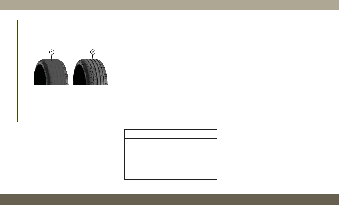
Tread Wear Indicators
Tread wear indicators are in the original
equipment tires to help you in determining
when your tires should be replaced.
These indicators are molded into the bottom
of the tread grooves. They will appear as
bands when the tread depth becomes a
1/16 of an inch (1.6 mm). When the tread is
worn to the tread wear indicators, the tire
should be replaced.
Refer to “Replacement Tires” in this section
for further information.
Life Of Tire
The service life of a tire is dependent upon
varying factors including, but not limited to:
• Driving style.
• Tire pressure - Improper cold tire inflation
pressures can cause uneven wear patterns
to develop across the tire tread. These ab-
normal wear patterns will reduce tread life,
resulting in the need for earlier tire replace-
ment.
• Distance driven.
• Performance tires, tires with a speed rating
of V or higher, and Summer tires typically
have a reduced tread life. Rotation of these
tires per the vehicle scheduled mainte-
nance is highly recommended.
WARNING!
Tires and the spare tire should be replaced
after six years, regardless of the remaining
tread. Failure to follow this warning can
result in sudden tire failure. You could lose
control and have a collision resulting in
serious injury or death.
NOTE:
Wheel Valve Stem must be replaced as well
when installing new tires due to wear and tear
in existing tires.
Keep dismounted tires in a cool, dry place
with as little exposure to light as possible.
Protect tires from contact with oil, grease,
and gasoline.
Replacement Tires
The tires on your new vehicle provide a bal-
ance of many characteristics. They should be
inspected regularly for wear and correct cold
tire inflation pressures. The manufacturer
strongly recommends that you use tires
equivalent to the originals in size, quality and
performance when replacement is needed.
Refer to the paragraph on “Tread Wear Indi-
cators” in this section. Refer to the Tire and
Loading Information placard or the Vehicle
Certification Label for the size designation of
your tire. The Load Index and Speed Symbol
for your tire will be found on the original
equipment tire sidewall.
Tire Tread
1 — Worn Tire
2 — New Tire
SERVICING AND MAINTENANCE
266
See the Tire Sizing Chart example found in
the “Tire Safety Information” section of this
manual for more information relating to the
Load Index and Speed Symbol of a tire.
It is recommended to replace the two front
tires or two rear tires as a pair. Replacing just
one tire can seriously affect your vehicle’s
handling. If you ever replace a wheel, make
sure that the wheel’s specifications match
those of the original wheels.
It is recommended you contact an authorized
tire dealer or original equipment dealer with
any questions you may have on tire specifica-
tions or capability. Failure to use equivalent
replacement tires may adversely affect the
safety, handling, and ride of your vehicle.
WARNING!
• Do not use a tire, wheel size, load rating,
or speed rating other than that specified
for your vehicle. Some combinations of
unapproved tires and wheels may
change suspension dimensions and per-
formance characteristics, resulting in
WARNING!
changes to steering, handling, and brak-
ing of your vehicle. This can cause un-
predictable handling and stress to steer-
ing and suspension components. You
could lose control and have a collision
resulting in serious injury or death. Use
only the tire and wheel sizes with load
ratings approved for your vehicle.
• Never use a tire with a smaller load index
or capacity, other than what was origi-
nally equipped on your vehicle. Using a
tire with a smaller load index could re-
sult in tire overloading and failure. You
could lose control and have a collision.
• Failure to equip your vehicle with tires
having adequate speed capability can
result in sudden tire failure and loss of
vehicle control.
CAUTION!
Replacing original tires with tires of a
different size may result in false speedom-
eter and odometer readings.
Tire Types
All Season Tires — If Equipped
All Season tires provide traction for all sea-
sons (Spring, Summer, Fall, and Winter).
Traction levels may vary between different all
season tires. All season tires can be identified
by the M+S, M&S, M/S or MS designation on
the tire sidewall. Use all season tires only in
sets of four; failure to do so may adversely
affect the safety and handling of your vehicle.
Summer Or Three Season Tires —
If Equipped
Summer tires provide traction in both wet
and dry conditions, and are not intended to
be driven in snow or on ice. If your vehicle is
equipped with Summer tires, be aware these
tires are not designed for Winter or cold
driving conditions. Install Winter tires on your
vehicle when ambient temperatures are less
than 40°F (5°C) or if roads are covered with
ice or snow. For more information, contact an
authorized dealer.
Summer tires do not contain the all season
designation or mountain/snowflake symbol
on the tire sidewall. Use Summer tires only in
267

sets of four; failure to do so may adversely
affect the safety and handling of your vehicle.
WARNING!
Do not use Summer tires in snow/ice con-
ditions. You could lose vehicle control,
resulting in severe injury or death. Driving
too fast for conditions also creates the
possibility of loss of vehicle control.
Snow Tires
Some areas of the country require the use of
snow tires during the Winter. Snow tires can
be identified by a “mountain/snowflake”
symbol on the tire sidewall.
If you need snow tires,
select tires equivalent
in size and type to the
original equipment
tires. Use snow tires
only in sets of four;
failure to do so may
adversely affect the
safety and handling of your vehicle.
S
now tires generally have lower speed ratings
than what was originally equipped with your
vehicle and should not be operated at sus-
tained speeds over 75 mph (120 km/h). For
speeds above 75 mph (120 km/h) refer to
original equipment or an authorized tire dealer
for recommended safe operating speeds, load-
ing and cold tire inflation pressures.
While studded tires improve performance on
ice, skid and traction capability on wet or dry
surfaces may be poorer than that of non-
studded tires. Some states prohibit studded
tires; therefore, local laws should be checked
before using these tire types.
Spare Tires — If Equipped
NOTE:
For vehicles equipped with Tire Service Kit
instead of a spare tire, please refer to “Tire
Service Kit” in “In Case Of Emergency” in
the Owner’s Manual for further information.
CAUTION!
Because of the reduced ground clearance,
do not take your vehicle through an auto-
matic car wash with a compact or limited
use temporary spare installed. Damage to
the vehicle may result.
Refer to the “Towing Requirements - Tires” in
“Starting And Operating” in the Owner’s
Manual for restrictions when towing with a
spare tire designated for temporary emer-
gency use.
Spare Tire Matching Original Equipped Tire
And Wheel — If Equipped
Your vehicle may be equipped with a spare
tire and wheel equivalent in look and func-
tion to the original equipment tire and wheel
found on the front or rear axle of your vehicle.
This spare tire may be used in the tire rota-
tion for your vehicle. If your vehicle has this
option, refer to an authorized tire dealer for
the recommended tire rotation pattern.
SERVICING AND MAINTENANCE
268
Compact Spare Tire — If Equipped
The compact spare is for temporary emer-
gency use only. You can identify if your ve-
hicle is equipped with a compact spare by
looking at the spare tire description on the
Tire and Loading Information Placard located
on the driver’s side door opening or on the
sidewall of the tire. Compact spare tire de-
scriptions begin with the letter “T” or “S”
preceding the size designation. Example:
T145/80D18 103M.
T,S=Temporary Spare Tire
Since this tire has limited tread life, the
original equipment tire should be repaired (or
replaced) and reinstalled on your vehicle at
the first opportunity.
Do not install a wheel cover or attempt to
mount a conventional tire on the compact
spare wheel, since the wheel is designed
specifically for the compact spare tire. Do not
install more than one compact spare tire and
wheel on the vehicle at any given time.
WARNING!
Compact and collapsible spares are for
temporary emergency use only. With these
spares, do not drive more than 50 mph
(80 km/h). Temporary use spares have lim-
ited tread life. When the tread is worn to
the tread wear indicators, the temporary
use spare tire needs to be replaced. Be
sure to follow the warnings, which apply
to your spare. Failure to do so could result
in spare tire failure and loss of vehicle
control.
Collapsible Spare Tire — If Equipped
The collapsible spare is for temporary emer-
gency use only. You can identify if your ve-
hicle is equipped with a collapsible spare by
looking at the spare tire description on the
Tire and Loading Information Placard located
on the driver’s side door opening or on the
sidewall of the tire.
Collapsible spare tire description example:
165/80-17 101P.
Since this tire has limited tread life, the
original equipment tire should be repaired (or
replaced) and reinstalled on your vehicle at
the first opportunity.
Inflate collapsible tire only after the wheel is
properly installed to the vehicle. Inflate the
collapsible tire using the electric air pump
before lowering the vehicle.
Do not install a wheel cover or attempt to
mount a conventional tire on the collapsible
spare wheel, since the wheel is designed
specifically for the collapsible spare tire.
WARNING!
Compact and Collapsible spares are for
temporary emergency use only. With these
spares, do not drive more than 50 mph
(80 km/h). Temporary use spares have lim-
ited tread life. When the tread is worn to the
tread wear indicators, the temporary use
spare tire needs to be replaced. Be sure to
follow the warnings, which apply to your
spare. Failure to do so could result in spare
tire failure and loss of vehicle control.
269

Full Size Spare — If Equipped
The full size spare is for temporary emer-
gency use only. This tire may look like the
originally equipped tire on the front or rear
axle of your vehicle, but it is not. This spare
tire may have limited tread life. When the
tread is worn to the tread wear indicators, the
temporary use full size spare tire needs to be
replaced. Since it is not the same as your
original equipment tire, replace (or repair)
the original equipment tire and reinstall on
the vehicle at the first opportunity.
Limited Use Spare — If Equipped
The limited use spare tire is for temporary
emergency use only. This tire is identified by
a label located on the limited use spare
wheel. This label contains the driving limita-
tions for this spare. This tire may look like the
original equipped tire on the front or rear axle
of your vehicle, but it is not. Installation of
this limited use spare tire affects vehicle
handling. Since it is not the same as your
original equipment tire, replace (or repair)
the original equipment tire and reinstall on
the vehicle at the first opportunity.
WARNING!
Limited use spares are for emergency use
only. Installation of this limited use spare
tire affects vehicle handling. With this tire,
do not drive more than the speed listed on
the limited use spare wheel. Keep inflated
to the cold tire inflation pressures listed on
your Tire and Loading Information Placard
located on the driver’s side B-Pillar or the
rear edge of the driver’s side door. Replace
(or repair) the original equipment tire at
the first opportunity and reinstall it on your
vehicle. Failure to do so could result in
loss of vehicle control.
Wheel And Wheel Trim Care
All wheels and wheel trim, especially alumi-
num and chrome plated wheels, should be
cleaned regularly using mild (neutral Ph)
soap and water to maintain their luster and to
prevent corrosion. Wash wheels with the
same soap solution recommended for the
body of the vehicle and remember to always
wash when the surfaces are not hot to the
touch.
Your wheels are susceptible to deterioration
caused by salt, sodium chloride, magnesium
chloride, calcium chloride, etc., and other
road chemicals used to melt ice or control
dust on dirt roads. Use a soft cloth or sponge
and mild soap to wipe away promptly. Do not
use harsh chemicals or a stiff brush. They
can damage the wheel’s protective coating
that helps keep them from corroding and
tarnishing.
CAUTION!
Avoid products or automatic car washes
that use acidic solutions or strong alkaline
additives or harsh brushes. Many aftermar-
ket wheel cleaners and automatic car
washes may damage the wheel's protective
finish. Such damage is not covered by the
New Vehicle Limited Warranty. Only car
wash soap, Mopar Wheel Cleaner or
equivalent is recommended.
When cleaning extremely dirty wheels includ-
ing excessive brake dust, care must be taken in
the selection of tire and wheel cleaning chemi-
SERVICING AND MAINTENANCE
270
cals and equipment to prevent damage to the
wheels. Mopar Wheel Treatment or Mopar
Chrome Cleaner or their equivalent is recom-
mended or select a non-abrasive, non-acidic
cleaner for aluminum or chrome wheels.
CAUTION!
Do not use scouring pads, steel wool, a
bristle brush, metal polishes or oven
cleaner. These products may damage the
wheel's protective finish. Such damage is
not covered by the New Vehicle Limited
Warranty. Only car wash soap, Mopar
Wheel Cleaner or equivalent is recom-
mended.
NOTE:
If you intend parking or storing your vehicle
for an extended period after cleaning the
wheels with wheel cleaner, drive your vehicle
and apply the brakes to remove the water
droplets from the brake components. This
activity will remove the red rust on the brake
rotors and prevent vehicle vibration when
braking.
Dark Vapor Chrome, Black Satin Chrome, or Low
Gloss Clear Coat Wheels
CAUTION!
If your vehicle is equipped with these
specialty wheels, DO NOT USE wheel
cleaners, abrasives, or polishing com-
pounds. They will permanently damage
this finish and such damage is not covered
by the New Vehicle Limited Warranty.
HAND WASH ONLY USING MILD SOAP
AND WATER WITH A SOFT CLOTH. Used
on a regular basis; this is all that is re-
quired to maintain this finish.
Tire Chains (Traction Devices) — Non-SRT
Use of traction devices require sufficient tire-
to-body clearance. Follow these recommen-
dations to guard against damage.
• Traction device must be of proper size for
the tire, as recommended by the traction
device manufacturer.
• Install on Rear Tires Only
• Due to limited clearance, Thule XG-12 Pro
or equivalent is recommended on P245/
70R17, 265/60R18 or 265/50R20 tires.
WARNING!
Using tires of different size and type (M+S,
Snow) between front and rear axles can
cause unpredictable handling. You could
lose control and have a collision.
CAUTION!
To avoid damage to your vehicle or tires,
observe the following precautions:
• Because of restricted traction device
clearance between tires and other sus-
pension components, it is important that
only traction devices in good condition
are used. Broken devices can cause se-
rious damage. Stop the vehicle immedi-
ately if noise occurs that could indicate
device breakage. Remove the damaged
parts of the device before further use.
• Install device as tightly as possible and
then retighten after driving about ½ mile
(0.8 km).
271
CAUTION!
• Do not exceed 30 mph (48 km/h).
• Drive cautiously and avoid severe turns
and large bumps, especially with a
loaded vehicle.
• Do not drive for a prolonged period on
dry pavement.
• Observe the traction device manufactur-
er’s instructions on the method of instal-
lation, operating speed, and conditions
for use. Always use the suggested oper-
ating speed of the device manufacturer’s
if it is less than 30 mph (48 km/h).
• Do not use traction devices on a com-
pact spare tire.
Tire Chains (Traction Devices) — SRT
Use of traction devices require sufficient tire-
to-body clearance. Follow these recommen-
dations to guard against damage.
• Traction device must be of proper size for
the tire, as recommended by the traction
device manufacturer.
• Install on Rear Tires Only
• Due to limited clearance, RUD-GRIP
4X4 or Equivalent is recommended on
295/45R20 tires.
WARNING!
Using tires of different size and type
(M+S, Snow) between front and rear axles
can cause unpredictable handling. You
could lose control and have a collision.
CAUTION!
To avoid damage to your vehicle or tires,
observe the following precautions:
• Because of restricted traction device
clearance between tires and other sus-
pension components, it is important
that only traction devices in good condi-
tion are used. Broken devices can cause
serious damage. Stop the vehicle imme-
diately if noise occurs that could indi-
cate device breakage. Remove the dam-
aged parts of the device before further
use.
CAUTION!
• Install device as tightly as possible and
then retighten after driving about ½ mile
(0.8 km).
• Do not exceed 30 mph (48 km/h).
• Drive cautiously and avoid severe turns
and large bumps, especially with a
loaded vehicle.
• Do not drive for a prolonged period on
dry pavement.
• Observe the traction device manufactur-
er’s instructions on the method of instal-
lation, operating speed, and conditions
for use. Always use the suggested oper-
ating speed of the device manufacturer’s
if it is less than 30 mph (48 km/h).
• Do not use traction devices on a com-
pact spare tire.
Tire Rotation Recommendations
The tires on the front and rear of your vehicle
operate at different loads and perform differ-
ent steering, handling, and braking func-
tions. For these reasons, they wear at unequal
rates.
SERVICING AND MAINTENANCE
272
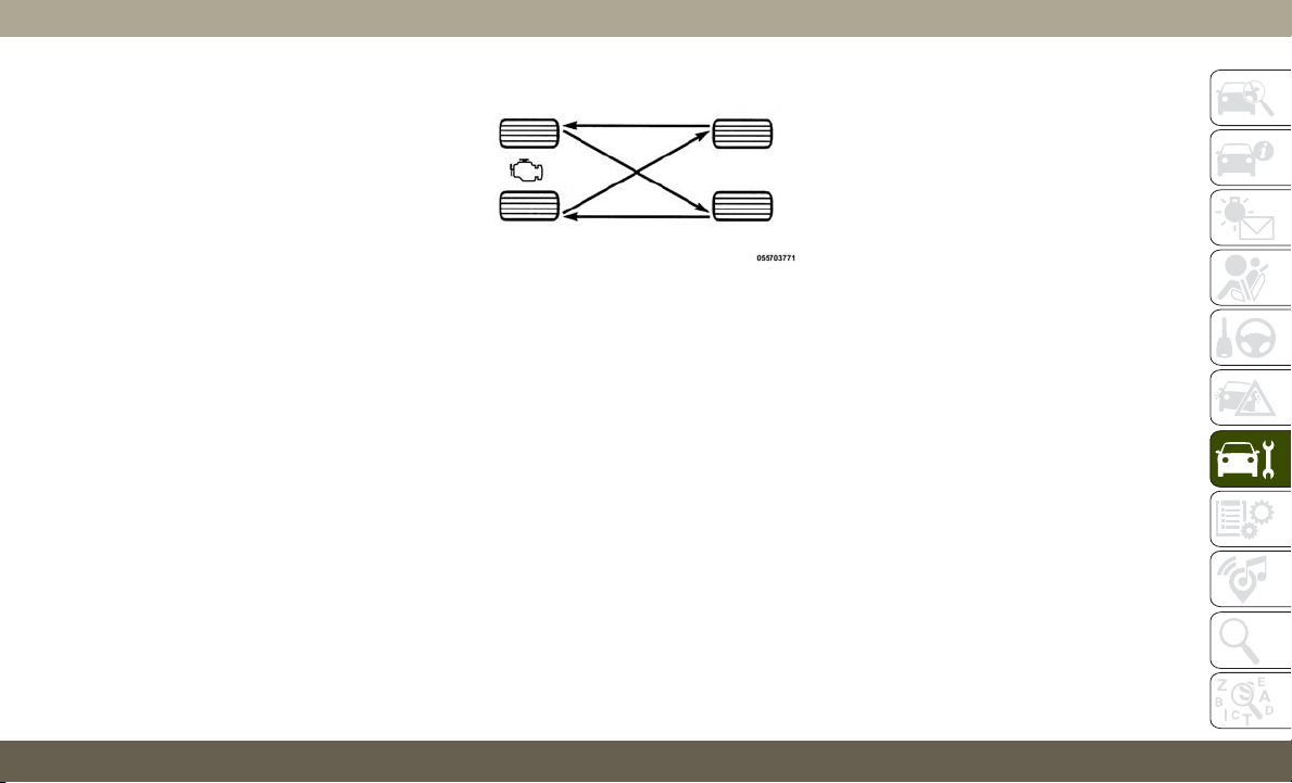
These effects can be reduced by timely rota-
tion of tires. The benefits of rotation are
especially worthwhile with aggressive tread
designs such as those on On/Off-Road type
tires. Rotation will increase tread life, help to
maintain mud, snow, and wet traction levels,
and contribute to a smooth, quiet ride.
Refer to the “Maintenance Plan” for the
proper maintenance intervals. More frequent
rotation is permissible if desired. The reasons
for any rapid or unusual wear should be
corrected prior to rotation being performed.
NOTE:
The premium Tire Pressure Monitor System
will automatically locate the pressure values
displayed in the correct vehicle position fol-
lowing a tire rotation.
The suggested rotation method is the
“rearward-cross” shown in the following dia-
gram.
DEPARTMENT OF
TRANSPORTATION
UNIFORM TIRE QUALITY
GRADES
The following tire grading categories
were established by the National High-
way Traffic Safety Administration. The
specific grade rating assigned by the
tire's manufacturer in each category is
shown on the sidewall of the tires on
your vehicle.
All passenger vehicle tires must con-
form to Federal safety requirements in
addition to these grades.
Treadwear
The Treadwear grade is a comparative
rating, based on the wear rate of the
tire when tested under controlled con-
ditions on a specified government test
course. For example, a tire graded
150 would wear one and one-half
times as well on the government
course as a tire graded 100. The rela-
tive performance of tires depends
upon the actual conditions of their
use, however, and may depart signifi-
cantly from the norm due to variations
in driving habits, service practices,
and differences in road characteristics
and climate.
Tire Rotation
273

Traction Grades
The Traction grades, from highest to
lowest, are AA, A, B, and C. These
grades represent the tire's ability to
stop on wet pavement, as measured
under controlled conditions on speci-
fied government test surfaces of as-
phalt and concrete. A tire marked C
may have poor traction performance.
WARNING!
The traction grade assigned to this
tire is based on straight-ahead
braking traction tests, and does
not include acceleration, cornering,
hydroplaning, or peak traction char-
acteristics.
Temperature Grades
The Temperature grades are A (the
highest), B, and C, representing the
tire's resistance to the generation of
heat and its ability to dissipate heat,
when tested under controlled condi-
tions on a specified indoor laboratory
test wheel.
Sustained high temperature can cause
the material of the tire to degenerate
and reduce tire life, and excessive
temperature can lead to sudden tire
failure. The grade C corresponds to a
level of performance, which all pas-
senger vehicle tires must meet under
the Federal Motor Vehicle Safety Stan-
dard No. 109. Grades B and A repre-
sent higher levels of performance on
the laboratory test wheel, than the
minimum required by law.
WARNING!
The temperature grade for this tire
is established for a tire that is prop-
erly inflated and not overloaded.
Excessive speed, under-inflation, or
excessive loading, either separately
or in combination, can cause heat
buildup and possible tire failure.
INTERIORS
Seats And Fabric Parts
Use Mopar Total Clean to clean fabric uphol-
stery and carpeting.
WARNING!
Do not use volatile solvents for cleaning
purposes. Many are potentially flam-
mable, and if used in closed areas they
may cause respiratory harm.
SERVICING AND MAINTENANCE
274
Seat Belt Maintenance
Do not bleach, dye or clean the belts with
chemical solvents or abrasive cleaners. This
will weaken the fabric. Sun damage can also
weaken the fabric.
If the belts need cleaning, use a mild soap
solution or lukewarm water. Do not remove
the belts from the vehicle to wash them. Dry
with a soft cloth.
Replace the belts if they appear frayed or
worn or if the buckles do not work properly.
WARNING!
A frayed or torn belt could rip apart in a
collision and leave you with no protection.
Inspect the belt system periodically,
checking for cuts, frays, or loose parts.
Damaged parts must be replaced immedi-
ately. Do not disassemble or modify the
system. Seat belt assemblies must be re-
placed after a collision if they have been
damaged (i.e., bent retractor, torn web-
bing, etc.).
Plastic And Coated Parts
U
se Mopar Total Clean to clean vinyl upholstery.
CAUTION!
• Direct contact of air fresheners, insect
repellents, suntan lotions, or hand sani-
tizers to the plastic, painted, or deco-
rated surfaces of the interior may cause
permanent damage. Wipe away immedi-
ately.
• Damage caused by these type of prod-
ucts may not be covered by your New
Vehicle Limited Warranty.
Cleaning Plastic Instrument Cluster Lenses
The lenses in front of the instruments in this
vehicle are molded in clear plastic. When
cleaning the lenses, care must be taken to
avoid scratching the plastic.
1. Clean with a wet soft cloth. A mild soap
solution may be used, but do not use high
alcohol content or abrasive cleaners. If
soap is used, wipe clean with a clean
damp cloth.
2. Dry with a soft cloth.
Leather Parts
Mopar Total Clean is specifically recom-
mended for leather upholstery.
Your leather upholstery can be best preserved
by regular cleaning with a damp soft cloth.
Small particles of dirt can act as an abrasive
and damage the leather upholstery and
should be removed promptly with a damp
cloth. Stubborn soils can be removed easily
with a soft cloth and Mopar Total Clean. Care
should be taken to avoid soaking your leather
upholstery with any liquid. Please do not use
polishes, oils, cleaning fluids, solvents, de-
tergents, or ammonia-based cleaners to clean
your leather upholstery. Application of a
leather conditioner is not required to main-
tain the original condition.
NOTE:
If equipped with light colored leather, it tends
to show any foreign material, dirt, and fabric
dye transfer more so than darker colors. The
leather is designed for easy cleaning, and
FCA recommends Mopar total care leather
cleaner applied on a cloth to clean the leather
seats as needed.
275

CAUTION!
Do not use Alcohol and Alcohol-based
and/or Ketone based cleaning products to
clean leather upholstery, as damage to the
upholstery may result.
Glass Surfaces
All glass surfaces should be cleaned on a
regular basis with Mopar Glass Cleaner, or
any commercial household-type glass
cleaner. Never use an abrasive type cleaner.
Use caution when cleaning the inside rear
window equipped with electric defrosters or
windows equipped with radio antennas. Do
not use scrapers or other sharp instruments
that may scratch the elements.
When cleaning the rear view mirror, spray
cleaner on the towel or cloth that you are
using. Do not spray cleaner directly on the
mirror.
SERVICING AND MAINTENANCE
276
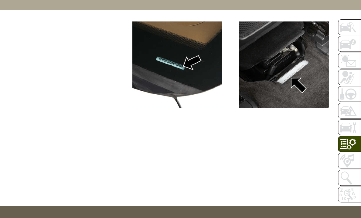
IDENTIFICATION DATA
Vehicle Identification Number
The Vehicle Identification Number (VIN) is
found on a label located on the left front
corner of the instrument panel pad, visible
from outside of the vehicle through the wind-
shield. This number also is stamped on the
right front floor, behind the right front seat.
Move the right front seat forward to allow
better viewing of the stamped VIN. This num-
ber also appears on the Automobile Informa-
tion Disclosure Label affixed to a window on
your vehicle. Save this label for a convenient
record of your vehicle identification number
and optional equipment.
NOTE:
It is illegal to remove or alter the VIN.
Windshield VIN Label Location Right Front Body VIN Location
277

WHEEL AND TIRE TORQUE
SPECIFICATIONS
Proper lug nut/bolt torque is very important to
ensure that the wheel is properly mounted to
the vehicle. Any time a wheel has been re-
moved and reinstalled on the vehicle, the lug
nuts/bolts should be torqued using a properly
calibrated torque wrench using a high quality
six sided (hex) deep wall socket.
Torque Specifications
Base Model Vehicle
Lug Nut/Bolt
Torque
**Lug Nut/Bolt
Size
Lug Nut/Bolt
Socket Size
130 Ft-Lbs
(176 N·m)
M14x1.50 22mm
SRT Model Vehicle
Lug Nut/Bolt
Torque
**Lug Nut/Bolt
Size
Lug Nut/Bolt
Socket Size
110 Ft-Lbs
(149 N·m)
M14x1.50 22mm
**Use only your authorized dealer recom-
mended lug nuts/bolts and clean or remove
any dirt or oil before tightening.
Inspect the wheel mounting surface prior to
mounting the tire and remove any corrosion
or loose particles.
Tighten the lug nuts/bolts in a star pattern
until each nut/bolt has been tightened twice.
Ensure that the socket is fully engaged on the
lug nut/bolt (do not insert it half way).
NOTE:
If in doubt about the correct tightness, have
them checked with a torque wrench by your
authorized dealer or service station.
After 25 miles (40 km), check the lug nut/
bolt torque to be sure that all the lug nuts/
bolts are properly seated against the wheel.
WARNING!
To avoid the risk of forcing the vehicle off
the jack, do not tighten the lug nuts/bolts
fully until the vehicle has been lowered.
Failure to follow this warning may result in
personal injury.
Torque Pattern
TECHNICAL SPECIFICATIONS
278
FUEL REQUIREMENTS —
GASOLINE ENGINE
3.6L Engine
Do not use E-85 flex fuel or ethanol blends
greater than 15% in this engine.
T
hese engines are de-
signed to meet all emis-
sions regulations and
provide optimum fuel
economy and perfor-
mance when using high
quality unleaded “Regu-
lar” gasoline having a
posted octane number of 87 as specified by
the (R+M)/2 method. The use of higher octane
“Premium” gasoline is not required, as it will
not provide any benefit over “Regular” gasoline
in these engines.
While operating on gasoline with an octane
number of 87, hearing a light knocking sound
from the engine is not a cause for concern.
However, if the engine is heard making a
heavy knocking sound, see an dealer imme-
diately. Use of gasoline with an octane num-
ber lower than 87 can cause engine failure
and may void or not be covered by the New
Vehicle Limited Warranty.
Poor quality gasoline can cause problems
such as hard starting, stalling, and hesita-
tions. If you experience these symptoms, try
another brand of gasoline before considering
service for the vehicle.
5.7L Engine
Do not use E-85 flex fuel or ethanol blends
greater than 15% in this engine.
T
his engine is designed
to meet all emissions
regulations and pro-
vide satisfactory fuel
economy and perfor-
mance when using high-
quality unleaded gaso-
line having an octane
range of 87 to 89 as specified by the (R+M)/
2 method. The use of 89 octane “Plus” gaso-
line is recommended for optimum performance
and fuel economy.
While operating on gasoline with an octane
number of 87, hearing a light knocking sound
from the engine is not a cause for concern.
However, if the engine is heard making a
heavy knocking sound, see your dealer imme-
diately. Use of gasoline with an octane num-
ber lower than 87 can cause engine failure
and may void or not be covered by the New
Vehicle Limited Warranty.
Poor quality gasoline can cause problems
such as hard starting, stalling, and hesita-
tions. If you experience these symptoms, try
another brand of gasoline before considering
service for the vehicle.
6.2L Supercharged And 6.4L Engine
Do not use E-85 flex fuel or ethanol blends
greater than 15% in this engine.
These engines are de-
signed to meet all
emissions regulations,
provide optimal fuel
economy and perfor-
mance when using
high-quality unleaded
RECOMMENDED OCTANE RATING
(R+M)/2 METHOD
87
RECOMMENDED OCTANE RATING
(R+M)/2 METHOD
89
RECOMMENDED OCTANE RATING
(R+M)/2 METHOD
91
279

“Premium” gasoline having a posted octane
number of 91 as specified by the (R+M)/
2 method. The use of 91 or higher octane
“Premium” gasoline is required in these en-
gines.
While operating on gasoline with the required
octane number, hearing a light knocking
sound from the engine is not a cause for
concern. However, if the engine is heard
making a heavy knocking sound, see your
dealer immediately. Use of gasoline with a
lower than recommended octane number can
cause engine failure and may void or not be
covered by the New Vehicle Limited War-
ranty.
Poor quality gasoline can cause problems
such as hard starting, stalling, and hesita-
tions. If you experience these symptoms, try
another brand of gasoline before considering
service for the vehicle.
Materials Added To Fuel
Designated TOP TIER
Detergent Gasoline
contains a higher level
of detergents to fur-
ther aide in minimiz-
ing engine and fuel
system deposits. When
available, the usage of
TOP TIER Detergent gasoline is recom-
mended. Visit www.toptiergas.com for a list
of TOP TIER Detergent Gasoline Retailers.
Indiscriminate use of fuel system cleaning
agents should be avoided. Many of these
materials intended for gum and varnish re-
moval may contain active solvents or similar
ingredients. These can harm fuel system gas-
ket and diaphragm materials.
FUEL REQUIREMENTS –
DIESEL ENGINE
Federal law requires that you must fuel this
vehicle with Ultra Low Sulfur Highway Diesel
fuel (15 ppm Sulfur maximum) and prohibits
the use of Low Sulfur Highway Diesel fuel
(500 ppm Sulfur maximum) to avoid damage
to the emissions control system.
Use good quality diesel fuel from a reputable
supplier in your vehicle. For most year-round
service, No. 2 diesel fuel meeting ASTM
(formerly known as the American Society for
Testing and Materials) specification
D-975 Grade S15 will provide good perfor-
mance. If the vehicle is exposed to extreme
cold (below 20°F or -7°C), or is required to
operate at colder-than-normal conditions for
prolonged periods, use climatized No. 2 die-
sel fuel or dilute the No. 2 diesel fuel with
50% No. 1 diesel fuel. This will provide
better protection from fuel gelling or wax-
plugging of the fuel filters.
TECHNICAL SPECIFICATIONS
280
WARNING!
Do not use alcohol or gasoline as a fuel
blending agent. They can be unstable un-
der certain conditions and hazardous or
explosive when mixed with diesel fuel.
Diesel fuel is seldom completely free of wa-
ter. To prevent fuel system trouble, drain the
accumulated water from the fuel/water sepa-
rator using the fuel/water separator drain pro-
vided on the fuel filter housing. If you buy
good quality fuel and follow the cold weather
advice above, fuel conditioners should not be
required in your vehicle. If available in your
area, a high cetane “premium” diesel fuel
may offer improved cold-starting and
warm-up performance.
CAUTION!
If the “Water in Fuel Indicator Light” re-
mains on, DO NOT START engine before
you drain the water from the fuel filter(s) to
avoid engine damage. Refer to “Draining
Fuel/Water Separator Filter” in “Servicing
And Maintenance” in your Diesel Supple-
ment for further information, which can be
found with your online Owner’s Informa-
tion.
Diesel Fuel Specifications
This diesel engine has been developed to
take advantage of the high energy content
and generally lower cost No. 2 Ultra Low
Sulfur diesel fuel or No. 2 Ultra Low Sulfur
climatized diesel fuels.
NOTE:
• If you accidentally fill the fuel tank with
gasoline on your diesel vehicle, do not start
the engine. Damage to the engine and fuel
system could occur. Please call an autho-
rized dealer for service.
• A maximum blend of 5% biodiesel meeting
ASTM specification D-975 may be used
with your diesel engine without any adjust-
ments to regular service schedules.
• Commercially available fuel additives are
not necessary for the proper operation of
your diesel engine.
• No. 1 Ultra Low Sulfur diesel fuel should
only be used where extended arctic condi-
tions (-10°F or -23°C) exist.
281

FLUID CAPACITIES — NON SRT
U.S. Metric
Fuel (Approximate)
3.6L Engine 24.6 Gallons 93.1 Liters
5.7L Engine 24.6 Gallons 93.1 Liters
Engine Oil With Filter
3.6L Engine (SAE 0W-20, API Certified) 6 Quarts 5.6 Liters
5.7L Engine (SAE 0W-20, API Certified) 7 Quarts 6.6 Liters
Cooling System*
3.6L Engine (Mopar Antifreeze/Engine Coolant 10 Year/150,000 Mile Formula or
equivalent)
10.4 Quarts 9.9 Liters
5.7L Engine (Mopar Antifreeze/Engine Coolant 10 Year/150,000 Mile Formula or
equivalent) – Without Trailer Tow Package
15.4 Quarts 14.6 Liters
5.7L Engine (Mopar Antifreeze/Engine Coolant 10 Year/150,000 Mile Formula or
equivalent) – With Trailer Tow Package
16 Quarts 15.2 Liters
* Includes heater and coolant recovery bottle filled to MAX level.
FLUID CAPACITIES — SRT
U.S. Metric
Fuel (Approximate)
24.6 Gallons 93.1 Liters
Engine Oil With Filter
6.2 Liter Engine (SAE 0W-40, Synthetic API Certified, MS-12633) 8.3 Quarts 7.8 Liters
6.4 Liter Engine (SAE 0W-40, Synthetic API Certified, MS-12633) 7 Quarts 6.6 Liters
TECHNICAL SPECIFICATIONS
282

U.S. Metric
Cooling System*
6.2L Engine (Mopar Antifreeze/Engine Coolant 10 Year/150,000 Mile Formula that
meets the requirements of FCA Material Standard MS.90032.)
14.7 Quarts 13.9 Liters
6.2L Engine Intercooler (Mopar Antifreeze/Engine Coolant 10 Year/150,000 Mile For-
mula that meets the requirements of FCA Material Standard MS.90032.)
4.0 Quarts 3.9 Liters
6.4 Liter Engine (Mopar Antifreeze/Engine Coolant 10 Year/150,000 Mile Formula that
meets the requirements of FCA Material Standard MS.90032.)
16 Quarts 15.5 Liters
* Includes heater and coolant recovery bottle filled to MAX level.
FLUID CAPACITIES — DIESEL
U.S. Metric
Fuel (Approximate)
3.0L Diesel Engine 24.6 Gallons 93.1 Liters
Diesel Exhaust Fluid Tank 8 Gallons 30.3 Liters
Engine Oil With Filter
3.0 Liter Diesel Engine (SAE 5W-40 Synthetic, API CJ-4) 8 Quarts 7.7 Liters
Cooling System
3.0L Turbo Diesel Engine (Mopar Engine Coolant/Antifreeze 10 Year/150,000 Mile For-
mula OAT (Organic Additive Technology))
12 Quarts 11.4 Liters
283
FLUIDS AND LUBRICANTS — NON-SRT
Engine
Component Fluid, Lubricant, or Genuine Part
Engine Coolant We recommend you use Mopar Antifreeze/Coolant 10 Year/150,000 Mile Formula OAT (Organic
Additive Technology).
Engine Oil – 3.6L Engine We recommend you use API Certified SAE 0W-20 Engine Oil, meeting the requirements of FCA
Material Standard MS-6395 such as Mopar, Pennzoil, and Shell Helix. Refer to your engine oil
filler cap for correct SAE grade.
Engine Oil – 5.7L Engine We recommend you use API Certified SAE 5W-20 Engine Oil, meeting the requirements of FCA
Material Standard MS-6395 such as Mopar, Pennzoil, and Shell Helix. Refer to your engine oil
filler cap for correct SAE grade.
Engine Oil Filter We recommend you use Mopar Engine Oil Filter or equivalent.
Spark Plugs We recommend you use Mopar Spark Plugs.
Fuel Selection – 3.6L Engine 87 Octane, 0-15% Ethanol (Do Not Use E-85).
Fuel Selection – 5.7L Engine 89 Octane Recommended - 87 Octane Acceptable, 0-15% Ethanol (Do Not Use E-85).
CAUTION!
• Mixing of engine coolant (antifreeze)
other than specified Organic Additive
Technology (OAT) engine coolant (anti-
freeze), may result in engine damage
and may decrease corrosion protection.
CAUTION!
Organic Additive Technology (OAT) en-
gine coolant is different and should not
be mixed with Hybrid Organic Additive
Technology (HOAT) engine coolant (an-
tifreeze) or any “globally compatible”
coolant (antifreeze). If a non-OAT engine
CAUTION!
coolant (antifreeze) is introduced into
the cooling system in an emergency, the
cooling system will need to be drained,
flushed, and refilled with fresh OAT
coolant (conforming to MS.90032), by
an authorized dealer as soon as possible.
TECHNICAL SPECIFICATIONS
284
CAUTION!
• Do not use water alone or alcohol-based
engine coolant (antifreeze) products. Do
not use additional rust inhibitors or an-
tirust products, as they may not be com-
CAUTION!
patible with the radiator engine coolant
and may plug the radiator.
• This vehicle has not been designed for
use with propylene glycol-based engine
CAUTION!
coolant (antifreeze). Use of propylene
glycol-based engine coolant (antifreeze)
is not recommended.
Chassis
Component Fluid, Lubricant, or Genuine Part
Automatic Transmission Use only Mopar ZF 8&9 Speed ATF Automatic Transmission Fluid or equivalent. Failure to use the
correct fluid may affect the function or performance of your transmission.
Transfer Case – Single-Speed (Quadra-Trac I) We recommend you use Automatic Transmission Fluid 3353.
Transfer Case – Two-Speed (Quadra-Trac II) We recommend you use Mopar ATF+4 Automatic Transmission Fluid.
Axle Differential (Front) We recommend you use Mopar GL-5 Synthetic Axle Lubricant SAE 75W-85.
Axle Differential (Rear) – With Electronic Limited-
Slip Differential (ELSD)
We recommend you use Mopar GL-5 Synthetic Axle Lubricant SAE 75W-85 with friction modifier.
Axle Differential (Rear) – Without Electronic
Limited-Slip Differential (ELSD)
We recommend you use Mopar GL-5 Synthetic Axle Lubricant SAE 75W-85.
Brake Master Cylinder We recommend you use Mopar DOT 3 Brake Fluid, SAE J1703 should be used.
285

FLUIDS AND LUBRICANTS — SRT
Engine
Component Fluid, Lubricant or Genuine Part
Engine/Intercooler Coolant We recommend you use Mopar Antifreeze/Coolant 10 Year/150,000 Mile Formula OAT
(Organic Additive Technology) that meets the requirements of FCA Material Standard
MS.90032.
Engine Oil For best performance and maximum protection under all types of operating conditions, the
manufacturer only recommends full synthetic engine oils that meet the American Petroleum
Institute (API) categories of SN.
The manufacturer recommends the use of Pennzoil Ultra 0W-40 or equivalent Mopar engine
oil meeting the requirements of FCA Material Standard MS-12633 for use in all operating
temperatures.
Engine Oil Filter We recommend you use Mopar Engine Oil Filters.
Spark Plugs We recommend you use Mopar Spark Plugs.
Fuel Selection Premium Unleaded 91 Octane Only or Higher, 0-15% Ethanol (Do Not Use E-85).
Chassis
Component Fluid, Lubricant, or Genuine Part
Automatic Transmission Use only Mopar ZF 8&9 Speed ATF Automatic Transmission Fluid or equivalent. Failure to use
the correct fluid may affect the function or performance of your transmission.
Transfer Case – Single-Speed (Selec-Track) We recommend you use Mopar ATF+4 Automatic Transmission Fluid.
Axle Differential (Front) We recommend you use Mopar GL-5 Synthetic Axle Lubricant SAE 75W-85.
TECHNICAL SPECIFICATIONS
286

Component Fluid, Lubricant, or Genuine Part
Axle Differential (Rear) – With Electronic Limited-Slip
Differential (ELSD)
We recommend you use Mopar GL-5 Synthetic Axle Lubricant SAE 75W-85 with integrated
friction modifier.
Brake Master Cylinder We recommend you use Mopar DOT 3 Brake Fluid, SAE J1703 should be used. If DOT 3, SAE
J1703 brake fluid is not available, then DOT 4 is acceptable.
If using DOT 4 brake fluid, the fluid must be changed every 24 months. This interval is time
based only, mileage intervals do not apply.
FLUIDS AND LUBRICANTS — DIESEL
Engine
Component Fluid, Lubricant, or Genuine Part
Engine Coolant We recommend you use Mopar Antifreeze/Coolant 10 Year/150,000 Mile Formula OAT
(Organic Additive Technology).
Engine Oil We recommend you use 5W-40 synthetic engine oil such as Mopar or Shell Rotella that meets
FCA Material Standard MS-10902 and the API CJ-4 engine oil category is required.
Engine Oil Filter We recommend you use Mopar Engine Oil Filters.
Fuel Filters We recommend you use Mopar Fuel Filter. Must meet 3 micron rating. Using a fuel filter that
does not meet the manufacturers filtration and water separating requirements can severely impact
fuel system life and reliability.
287

Component Fluid, Lubricant, or Genuine Part
Fuel Selection Use good quality diesel fuel from a reputable supplier in your vehicle. Federal law requires
that you must fuel this vehicle with Ultra Low Sulfur Highway Diesel fuel (15 ppm Sulfur
maximum) and prohibits the use of Low Sulfur Highway Diesel fuel (500 ppm Sulfur
maximum) to avoid damage to the emissions control system. For most year-round service, No.
2 diesel fuel meeting ASTM specification D-975 Grade S15 will provide good performance.
We recommend you use a blend of up to 5% biodiesel, meeting ASTM specification
D-975 with your diesel engine.This vehicle is compatible with biodiesel blends greater than 5%
but no greater than 20% biodiesel meeting ASTM specification D-7467 provided the shortened
maintenance intervals are followed as directed.
Diesel Exhaust Fluid Mopar Diesel Exhaust Fluid (API Certified) (DEF) or equivalent that has been API Certified to
the ISO 22241 standard. Use of fluids not API Certified to ISO 22241 may result in system
damage.
NOTE:
If the vehicle is exposed to extreme cold
(below 20°F or -7°C), or is required to operate
at colder-than-normal conditions for pro-
longed periods, use climatized No. 2 diesel
fuel or dilute the No. 2 diesel fuel with 50%
No. 1 diesel fuel. This will provide better
protection from fuel gelling or wax-plugging
of the fuel filters.
TECHNICAL SPECIFICATIONS
288

Chassis
Component Fluid, Lubricant, or Genuine Part
Automatic Transmission Use only Mopar ZF 8&9 Speed ATF Automatic Transmission Fluid, or
equivalent. Failure to use the correct fluid may affect the function or
performance of your transmission.
Transfer Case – Single-Speed (Quadra-Trac I) We recommend you use Shell Automatic Transmission Fluid 3353.
Transfer Case – Two-Speed (Quadra-Trac II) We recommend you use Mopar ATF+4 Automatic Transmission Fluid.
Axle Differential (Front) We recommend you use Mopar GL-5 Synthetic Axle Lubricant SAE
75W-85.
Axle Differential (Rear) – With Electronic Limited-Slip Differential (ELSD) We recommend you use Mopar GL-5 Synthetic Axle Lubricant SAE
75W-85 with friction modifier additive.
Axle Differential (Rear) – Without Electronic Limited-Slip Differential
(ELSD)
We recommend you use Mopar GL-5 Synthetic Axle Lubricant SAE
75W-85.
Brake Master Cylinder We recommend you use Mopar DOT 3 Brake Fluid, SAE J1703 should be
used.
289

MOPAR ACCESSORIES
Authentic Accessories By Mopar
In choosing Authentic Accessories you gain
far more than expressive style, premium pro-
tection, or extreme entertainment, you also
benefit from enhancing your vehicle with
accessories that have been thoroughly tested
and factory-approved.
The following highlights just some of the
many Authentic Jeep Accessories by Mopar
featuring a fit, finish, and functionality spe-
cifically for your Jeep Grand Cherokee.
EXTERIOR:
• Front End Cover • Window Air Deflectors • Molded Splash Guards
• Wheels • Skid Plates • Tow Hooks
• Tubular Side Steps • Hitch Receiver • Front Air Deflector
INTERIOR:
• Carpet Floor Mats • Katzkin Leather Interiors • Cargo Net
• All-weather Floor Mats • Footwell Lighting • Bright Pedal Kit
• Cargo Barrier • Molded Cargo Tray • Door Sill Guards
ELECTRONICS:
• Remote Start • Mopar Connect • Rear View Camera
• Park Distance Sensors
TECHNICAL SPECIFICATIONS
290

CARRIERS:
• Sport Utility Bars • Roof Box Cargo Carrier • Roof Mount Bike Carrier
• Roof Mount Ski and Snowboard Carrier • Roof Mount Water Sports Carrier • Roof Mount Cargo Basket and Cargo Net
For the full line of Authentic Jeep Accesso-
ries by Mopar, visit your local dealership or
online at mopar.com for U.S. residents and
mopar.ca for Canadian residents.
NOTE:
All parts are subject to availability.
291

CYBERSECURITY
Your vehicle may be a connected vehicle and
may be equipped with both wired and wire-
less networks. These networks allow your
vehicle to send and receive information. This
information allows systems and features in
your vehicle to function properly.
Your vehicle may be equipped with certain
security features to reduce the risk of unau-
thorized and unlawful access to vehicle sys-
tems and wireless communications. Vehicle
software technology continues to evolve over
time and FCA US LLC, working with its sup-
pliers, evaluates and takes appropriate steps
as needed. Similar to a computer or other
devices, your vehicle may require software
updates to improve the usability and perfor-
mance of your systems or to reduce the po-
tential risk of unauthorized and unlawful ac-
cess to your vehicle systems.
The risk of unauthorized and unlawful access
to your vehicle systems may still exist, even if
the most recent version of vehicle software
(such as Uconnect software) is installed.
WARNING!
• It is not possible to know or to predict all
of the possible outcomes if your vehi-
cle’s systems are breached. It may be
possible that vehicle systems, including
safety related systems, could be im-
paired or a loss of vehicle control could
occur that may result in an accident
involving serious injury or death.
• ONLY insert media (e.g., USB, SD card,
or CD) into your vehicle if it came from a
trusted source. Media of unknown origin
could possibly contain malicious soft-
ware, and if installed in your vehicle, it
may increase the possibility for vehicle
systems to be breached.
• As always, if you experience unusual
vehicle behavior, take your vehicle to
your nearest authorized dealer immedi-
ately.
NOTE:
• FCA US LLC or your dealer may contact you
directly regarding software updates.
• To help further improve vehicle security
and minimize the potential risk of a secu-
rity breach, vehicle owners should:
–
Routinely check
www.driveuconnect.com
(U.S. Residents) or
www.driveuconnect.ca
(Canadian Residents) to learn about
available Uconnect software updates.
–
Only connect and use trusted media
devices (e.g. personal mobile phones,
USBs, CDs).
Privacy of any wireless and wired communi-
cations cannot be assured. Third parties may
unlawfully intercept information and private
communications without your consent. For
further information, refer to ”Data Collection
& Privacy” in your Uconnect Owner’s Manual
Supplement or “Onboard Diagnostic System
(OBD II) Cybersecurity” in “Getting To Know
Your Instrument Panel” in your Owner’s
Manual.
MULTIMEDIA
292
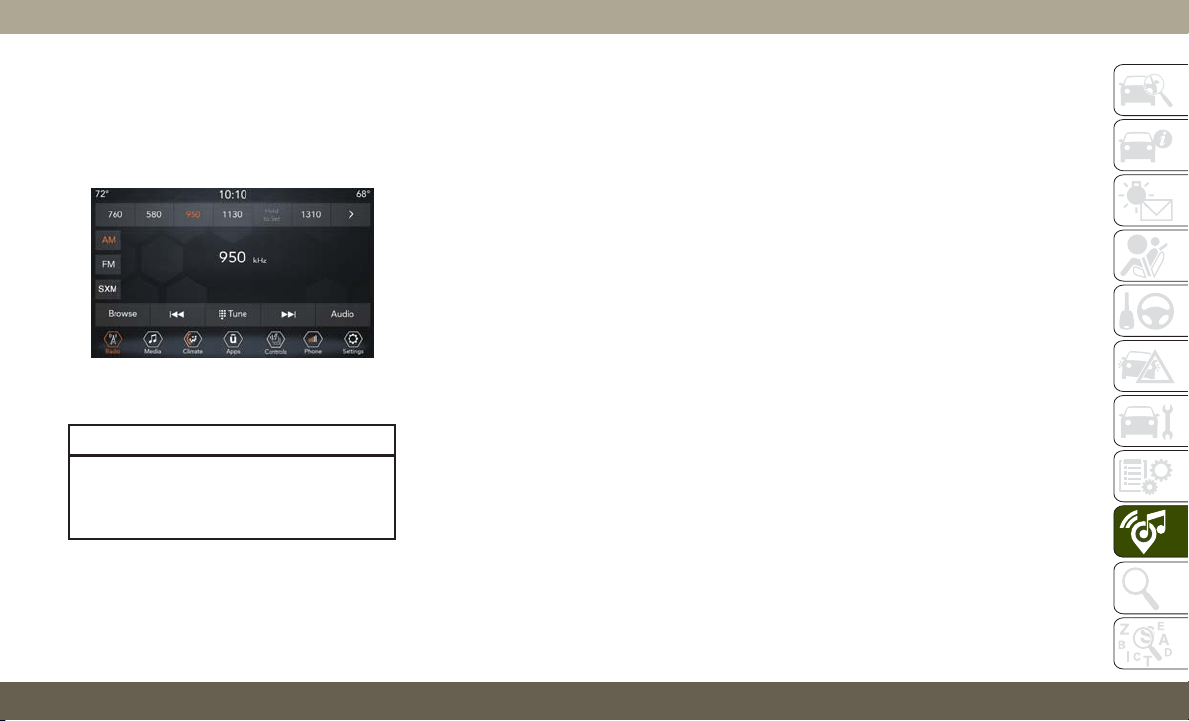
UCONNECT 4 WITH 7-INCH
DISPLAY
Uconnect 4 At A Glance
CAUTION!
Do NOT attach any object to the touch-
screen, doing so can result in damage to
the screen.
NOTE:
Uconnect screen images are for illustration
purposes only and may not reflect exact soft-
ware for your vehicle.
Setting The Time
1. For Uconnect 4, turn the unit on, and then
press the time display at the top of the
screen. Press “Yes.”
2. If the time is not displayed at the top of
the screen, press the “Settings” button on
the touchscreen. In the Settings screen,
press the “Clock & Date” button on the
touchscreen, then check or uncheck this
option.
3.
Press “+” or “–” next to “Set Time Hours”
and “Set Time Minutes” to adjust the time.
4. If these features are not available, un-
check the Sync Time box.
5. Press “X” to save your settings and exit
out of the Clock Setting screen.
Audio Settings
• Press the “Audio” button on the touch-
screen to activate the Audio settings screen
to adjust Balance\Fade, Equalizer, Speed
Adjusted Volume, Surround Sound, Loud-
ness, AUX Volume Offset, Auto Play, and
Radio Off With Door.
• You can return to the Radio screen by
pressing the “X” located at the top right.
Balance/Fade
• Press the “Balance/Fade” button on the
touchscreen to Balance audio between the
front speakers or fade the audio between
the rear and front speakers.
• Pressing the “Front,” “Rear,” “Left,” or
“Right” buttons on the touchscreen or
press and drag the Speaker Icon to adjust
the Balance/Fade.
Equalizer
• Press the “Equalizer” button on the touch-
screen to activate the Equalizer screen.
• Press the “+” or “–” buttons on the touch-
screen, or press and drag over the level bar
for each of the equalizer bands. The level
value, which spans between plus or minus
nine, is displayed at the bottom of each of
the bands.
Uconnect 4 With 7–inch Display Radio
Screen
293
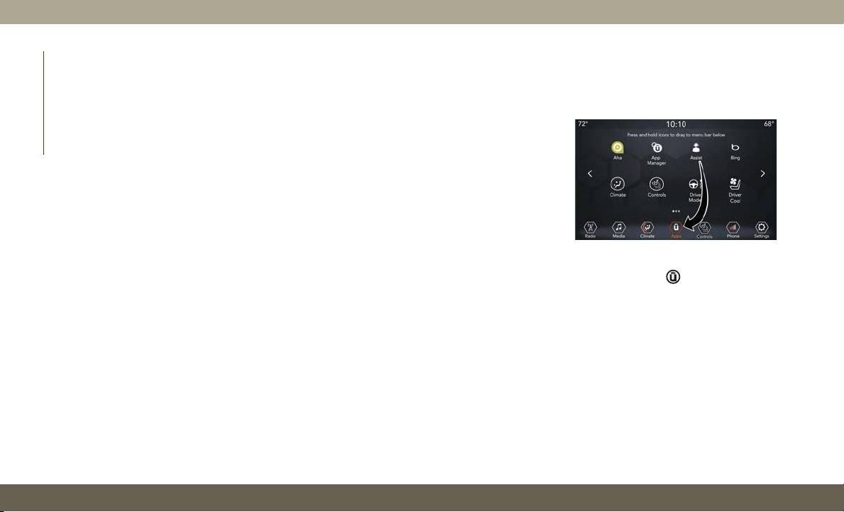
Speed Adjusted Volume
• Press the “Speed Adjusted Volume” button
on the touchscreen to activate the Speed
Adjusted Volume screen. The Speed Ad-
justed Volume is adjusted by pressing the
volume level indicator. This alters the auto-
matic adjustment of the audio volume with
variation to vehicle speed.
Loudness — If Equipped
• Press the “On” button on the touchscreen
to activate Loudness. Press “Off” to deac-
tivate this feature. When Loudness is On,
the sound quality at lower volumes
improves.
AUX Volume Offset
• Press the “AUX Volume Offset” button on
the touchscreen to activate the AUX Vol-
ume Offset screen. The AUX Volume Offset
is adjusted by pressing of the “+” and “–”
buttons. This alters the AUX input audio
volume. The level value, which spans be-
tween plus or minus three, is displayed
above the adjustment bar.
Auto Play — If Equipped
• Press the “Auto Play” button on the touch-
screen to activate the Auto Play screen. The
Auto Play feature has two settings “On”
and “Off.” With Auto Play on, music begins
playing from a connected device, immedi-
ately after it is connected to the radio.
Auto On Radio — If Equipped
• The Radio automatically turns on when
vehicle is in run or will recall whether it was
on or off at last ignition off.
Radio Off With Door — If Equipped
• Press the “Radio Off With Door” button on
the touchscreen to activate the Radio Off
With Door screen. The Radio Off With Door
feature, when activated, keeps the radio on
until the driver or passenger door is opened,
or when the Radio Off Delay selected time
has expired.
Drag & Drop Menu Bar
The Uconnect features and services in the
main menu bar are easily changed for your
convenience. Simply follow these steps:
1. Press the “Apps
” button to open the
App screen.
2. Press and hold, then drag the selected
App to replace an existing shortcut in the
main menu bar.
The new app shortcut, that was dragged down
onto the main menu bar, will now be an active
App/shortcut.
NOTE:
This feature is only available if the vehicle is
in PARK.
Uconnect 4 Main Menu
MULTIMEDIA
294
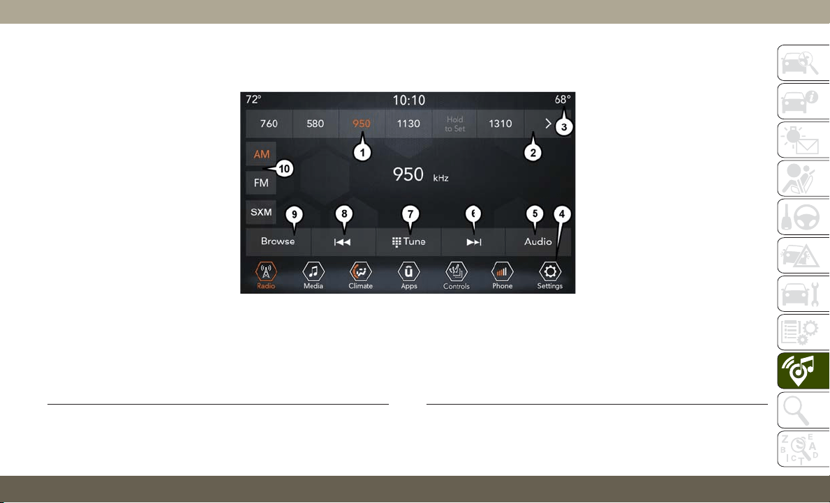
Radio
Uconnect 4 With 7–inch Display Radio
1 — Radio Station Presets
2 — Toggle Between Presets
3 — Status Bar
4 — Main Category Bar
5 — Audio Settings
6 — Seek Up
7 — Direct Tune To A Radio Station
8 — Seek Down
9 — Browse And Manage Presets
10 — Radio Bands
295

WARNING!
ALWAYS drive safely with your hands on
the wheel. You have full responsibility and
assume all risks related to the use of the
Uconnect features, SiriusXM Guardian
services, and applications in this vehicle.
Only use Uconnect features and SiriusXM
Guardian services when it is safe to do so.
Failure to do so may result in an accident
involving serious injury or death.
• To access the Radio mode, press the “Ra-
dio” button on the touchscreen.
Selecting Radio Stations
• Press the desired radio band (AM, FM or
SXM) button on the touchscreen.
Seek Up/Seek Down
• Press the Seek up or down arrow buttons on
the touchscreen for less than two seconds
to seek through radio stations.
• Press and hold either arrow button on the
touchscreen for more than two seconds to
bypass stations without stopping. The radio
will stop at the next listenable station once
the arrow button on the touchscreen is
released.
Direct Tune
• Tune directly to a radio station by pressing
the “Tune” button on the screen, and en-
tering the desired station number.
Store Radio Presets Manually
Your radio can store 36 total preset stations,
12 presets per band (AM, FM and SXM). They
are shown at the top of your radio screen. To
see the 12 preset stations per band, press the
arrow button on the touchscreen at the top
right of the screen to toggle between the two
sets of six presets.
To store a radio preset manually, follow the
steps below:
1. Tune to the desired station.
2. Press and hold the desired numbered but-
ton on the touchscreen for more than two
seconds or until you hear a confirmation
beep.
Android Auto — If Equipped
NOTE:
Feature availability depends on your carrier
and mobile phone manufacturer. Some
Android Auto features may or may not be
available in every region and/or language.
Android Auto is a feature of your Uconnect
system, and your Android 5.0 Lollipop, or
higher, powered smartphone with a data
plan, that allows you to project your smart-
phone and a number of its apps onto the
touchscreen radio display. Android Auto au-
tomatically brings you useful information,
and organizes it into simple cards that appear
just when they are needed. Android Auto can
be used with Google's best-in-class speech
technology, the steering wheel controls, the
knobs and buttons on your radio faceplate,
and the radio display’s touchscreen to control
many of your apps. To use Android Auto
follow the following steps:
1. Download the Android Auto app from the
Google Play store on your Android-
powered smartphone.
MULTIMEDIA
296
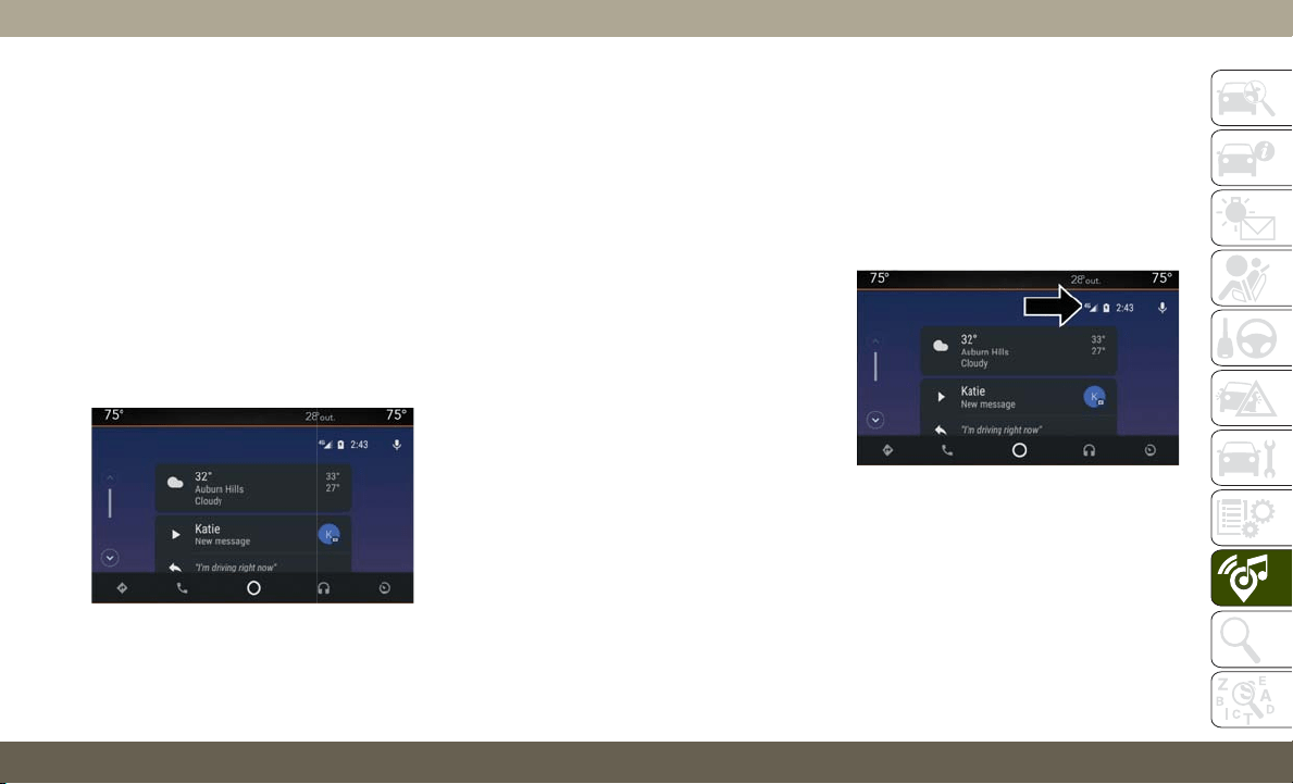
2. Connect your Android-powered smart-
phone to one of the media USB ports in
your vehicle. If you have not downloaded
the Android Auto app to your smartphone
before plugging in the device for the first
time, the app begins to download.
NOTE:
Be sure to use the factory-provided USB
cable that came with your phone, as af-
termarket cables may not work.
Your phone may ask you to approve the
use of the Android Auto app before use.
3. Once the device is connected and recog-
nized, Android Auto should automatically
launch, but you can also launch it by
touching the Android Auto icon on the
touchscreen, located under Apps.
Once Android Auto is up and running on your
Uconnect system, the following features can
be utilized using your smartphone’s data
plan:
• Google Maps for navigation
• Google Play Music, Spotify, iHeart Radio,
etc. for music
• Hands-free Calling, and Texting for commu-
nication
• Hundreds of compatible apps, and many
more!
NOTE:
To use Android Auto, make sure you are in an
area with cellular coverage. Android Auto
may use cellular data and your cellular cov-
erage is shown in the upper right corner of the
radio screen. Once Android Auto has made a
connection through USB, Android Auto will
also connect via Bluetooth.
NOTE:
Requires compatible smartphone running
Android 5.0 Lollipop or higher and download
app on Google Play. Android, Android Auto and
Google Play are trademarks of Google Inc.
Android Auto
Google Maps Data And Cellular Coverage
297
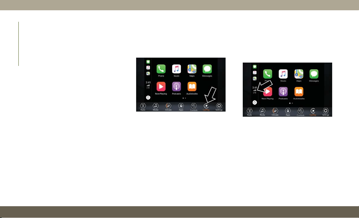
Apple CarPlay Integration — If Equipped
NOTE:
Feature availability depends on your carrier
and mobile phone manufacturer. Some Apple
CarPlay features may or may not be available
in every region and/or language.
Uconnect works seamlessly with Apple Car-
Play, the smarter, more secure way to use
your iPhone in the car, and stay focused on
the road. Use your Uconnect Touchscreen
display, the vehicle's knobs and controls, and
your voice with Siri to get access to Apple
Music, Maps, Messages, and more.
To use CarPlay, make sure you are using
iPhone 5 or later, have Siri enabled in Set-
tings, that your iPhone is unlocked for the
very first connection only, and then use the
following procedure:
1. Connect your iPhone to one of the media
USB ports in your vehicle.
NOTE:
Be sure to use the factory-provided Light-
ning cable that came with your phone, as
aftermarket cables may not work.
2. Once the device is connected and recog-
nized, CarPlay should automatically
launch, but you can also launch it by
touching the CarPlay icon on the touch-
screen, located under Apps.
Once CarPlay is up and running on your
Uconnect system, the following features can
be utilized using your iPhone’s data plan:
• Phone
• Music
• Messages
• Maps
NOTE:
To use CarPlay make sure that cellular data is
turned on, and that you are in an area with
cellular coverage. Your data and cellular cov-
erage is shown on the left side of the radio
screen.
NOTE:
Requires compatible iPhone. See dealer for
phone compatibility. Data plan rates apply.
Vehicle user interface is a product of Apple.
Apple CarPlay is a trademark of Apple Inc.
iPhone is a trademark of Apple Inc., regis-
tered in the US and other countries. Apple
terms of use and privacy statements apply.
Apple CarPlay
CarPlay Data And Cellular Coverage
MULTIMEDIA
298
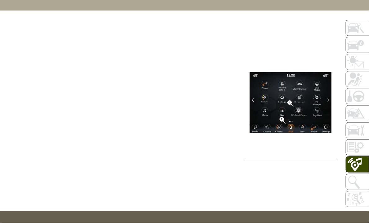
UCONNECT SETTINGS
The Uconnect system allows you to access
Customer Programmable feature settings
such as Display, Voice, Clock, Safety & Driv-
ing Assistance, Lights, Doors & Locks,
Auto-On Comfort & Remote Start, Engine Off
Options, Compass Settings, Audio, Phone/
Bluetooth, Suspension, SiriusXM Setup,
Restore Settings, Clear Personal Data, and
System Information through buttons on the
touchscreen.
Push the SETTINGS button (Uconnect 4), or
press the “Apps” button (Uconnect 4C/4C
NAV) located near the bottom of the touch-
screen, then press the “Settings” button on
the touchscreen to access the Settings
screen. When making a selection, scroll up or
down until the preferred setting is high-
lighted, then press the preferred setting until
a check-mark appears next to the setting,
showing that setting has been selected. The
following feature settings are available:
• Display • Engine Off Options
• Units • Camera
• Voice • Suspension
• Clock • Audio
• Safety & Driving
Assistance
• Phone/Bluetooth
• Mirrors & Wipers • Accessibility
• Lights • SiriusXM Setup
• Doors & Locks • Restore Settings
• Auto-On Comfort &
Remote Start
• Clear Personal Data
• Compass –
If Equipped
• System Information
NOTE:
Depending on the vehicles options, feature
settings may vary.
Refer to “Uconnect Settings” in “Multime-
dia” in the Owner’s Manual for further infor-
mation.
OFF ROAD PAGES —
IF EQUIPPED
Your vehicle is equipped with Off Road Pages,
which provides the vehicle status while operat-
ing on off road conditions. It supplies informa-
tion relating to the vehicle ride height, the
status of the transfer case, the pitch and roll of
the vehicle (if equipped), and the active Selec-
Terrain mode.
To access Off Road Pages, press the “Apps”
button on the touchscreen, and then select
“Off Road Pages”.
Off Road Pages has the following selectable
pages:
• Vehicle Dynamics
• Suspension
Main Menu
1 — Off Road Pages App
2 — Uconnect Apps Button
299
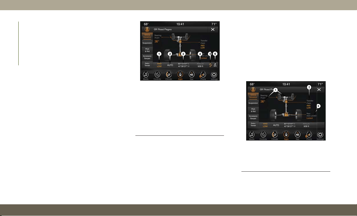
• Pitch and Roll — If Equipped
• Accessory Gauge
• Selec-Terrain — If Equipped
Off Road Pages Status Bar
The Off Road Pages Status Bar is located
along the bottom of Off Road Pages and is
present in each of the five selectable page
options. It provides continually updating in-
formation for the following items:
• Current Transfer Case Status (only appears
when in 4WD LOW)
• Current Selec-Terrain mode — If Equipped
• Current Latitude/Longitude
• Current Altitude of the vehicle
• Status of Hill Descent
• Selec-Speed Control and Selected Speed
in MPH (km/h)
Vehicle Dynamics
The Vehicle Dynamics page displays informa-
tion concerning the vehicle’s drivetrain.
The following information is displayed:
• Steering angle in degrees
• Status of Transfer case
• Status of the Rear Axles — If Equipped
Status Bar
1 — Transfer Case Status (Only when
in 4WD LOW)
2 — Selec-Terrain Mode — If Equipped
3 — Current Latitude/Longitude
4 — Current Altitude
5 — Hill Descent
6
— Selec-Speed Status And Set Speed
Vehicle Dynamics Menu
1 — Steering Angle
2 — Transfer Case Status
3 — Rear Axle Locker Status
MULTIMEDIA
300
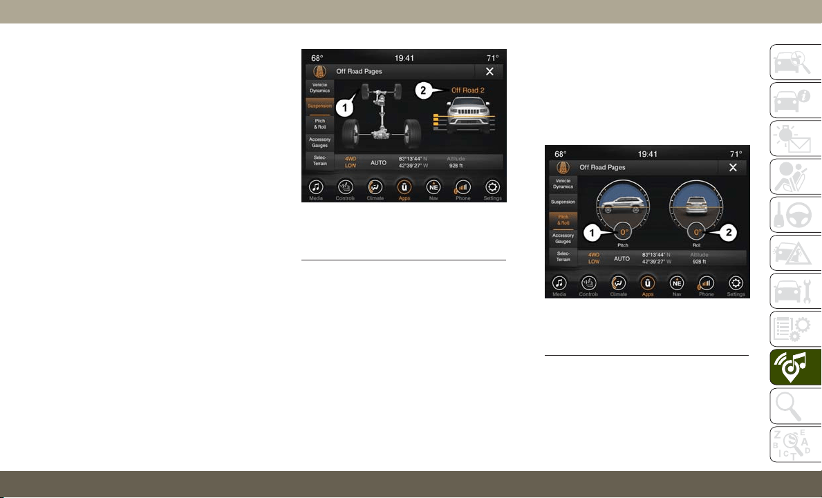
Suspension
The Suspension page displays information
concerning the vehicle’s suspension.
The following information is displayed:
• Suspension Articulation Indicator
• Current Ride Height Status — If Equipped
– Normal
– Off Road 1
– Off Road 2
– Entry/Exit
– Aero
NOTE:
The wheel articulation will be represented by
a yellow color in the Suspension Articulation
Indicator. If Ride Height is adjusted, the Ride
Height indicator on the screen will switch to
the appropriate height and the Suspension
Articulation Indicator will show the move-
ment and change in height.
Pitch And Roll
The Pitch And Roll page displays the vehi-
cle’s current pitch (angle up and down) and
roll (angle side to side) in degrees. The pitch
and roll gauges provide a visualization of the
current vehicle angle.
Suspension Menu
1 — Suspension Articulation Indicator
2 — Current Ride Height
Pitch And Roll Menu
1 — Current Pitch
2 — Current Roll
301
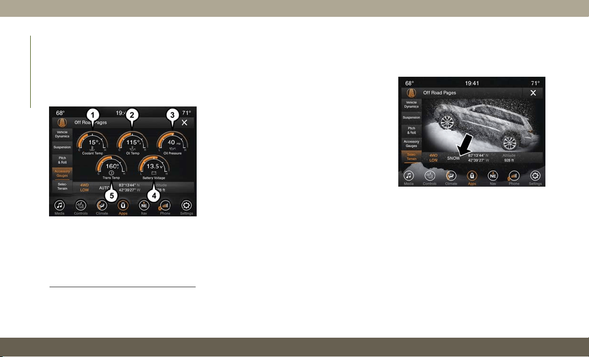
Accessory Gauges
The Accessory Gauges page displays the cur-
rent status of the vehicle’s Coolant Tempera-
ture, Oil Temperature, Oil Pressure (Gas Ve-
hicles Only), Transmission Temperature, and
Battery Voltage.
Selec-Terrain — If Equipped
The Selec-Terrain page displays the current
Selec-Terrain mode through a high resolution
image. Adjusting the Selec-Terrain mode will
alter the image on the screen. The vehicle
must be in the ON/RUN position to display
Selec-Terrain information.
The selectable modes are as follows:
• Snow
• Sand
• Auto — Default
• Mud
• Rock — Vehicle Must Be In 4 Wheel Drive
Low
NOTE:
While in the Selec-Terrain pages, the Off
Road Pages Status Bar will also display the
current Selec-Terrain mode.
Accessory Gauges Menu
1 — Coolant Temperature
2 — Oil Temperature
3 — Oil Pressure (Gas Vehicles Only)
4 — Battery Voltage
5 — Transmission Temperature
Current Selec-Terrain Mode
MULTIMEDIA
302
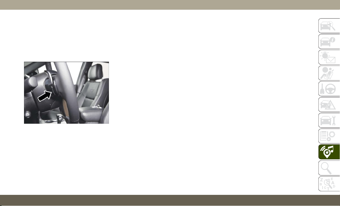
TIPS CONTROLS AND
GENERAL INFORMATION
Steering Wheel Audio Controls
The steering wheel audio controls are located
on the rear surface of the steering wheel.
Left Switch
• Push the switch up or down to search for
the next listenable station.
• Push the button in the center to select the
next preset radio station.
Right Switch
• Push the switch up or down to increase or
decrease the volume.
• Push the button in the center to change
modes AM/FM/SXM.
Reception Conditions
Reception conditions change constantly
while driving. Reception may be interfered
with by the presence of mountains, buildings
or bridges, especially when you are far away
from the broadcaster.
The volume may be increased when receiving
traffic alerts and news.
Care And Maintenance
Observe the following precautions to ensure
the system is fully operational:
• The display lens should not come into con-
tact with pointed or rigid objects which
could damage its surface; use a soft, dry,
anti-static cloth to clean and do not press.
• Never use alcohol, gas and derivatives to
clean the display lens.
• Prevent any liquid from entering the sys-
tem: this could damage it beyond repair.
Anti-Theft Protection
The system is equipped with an anti-theft
protection system based on the exchange of
information with the electronic control unit
(Body Computer) on the vehicle. This guaran-
tees maximum safety.
If the check has a positive outcome, the
system will start to operate. See an autho-
rized dealer for further information.
Steering Wheel Audio Controls
303
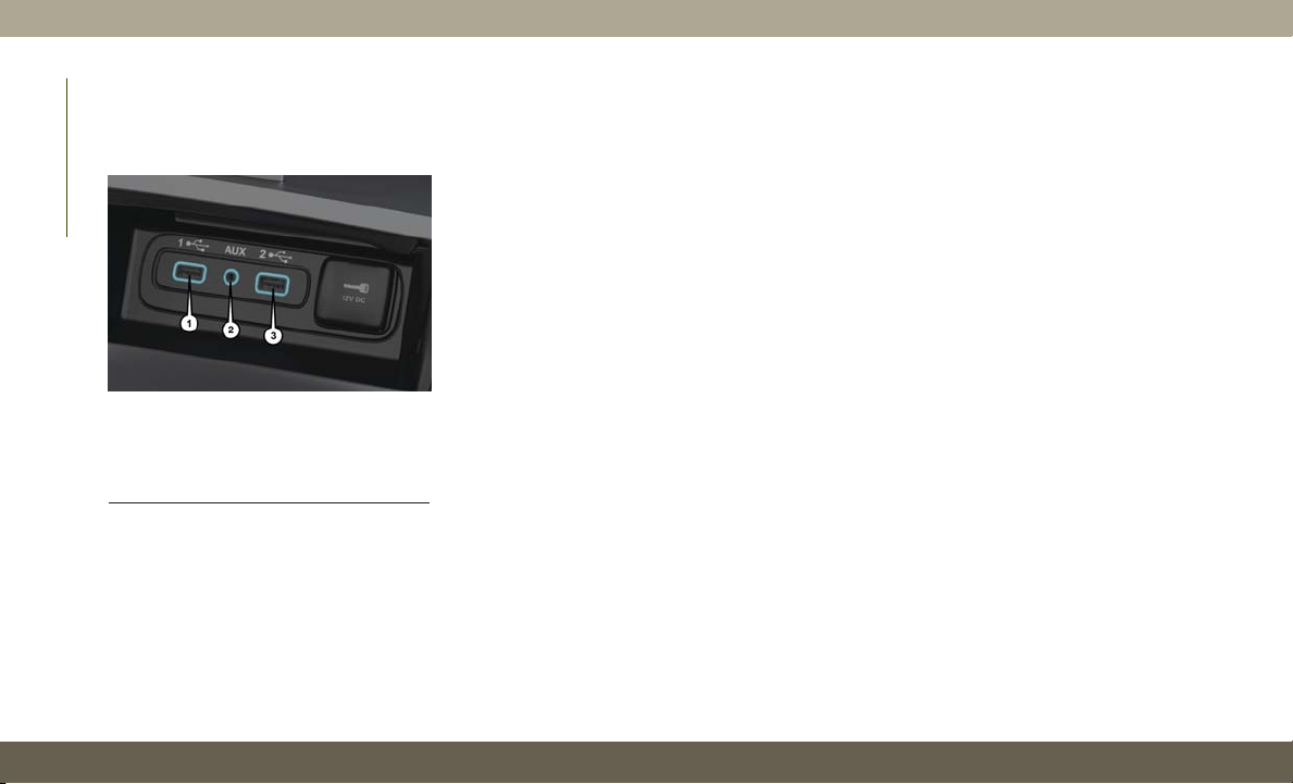
IPOD/USB/MEDIA PLAYER
CONTROL
There are many ways to play music from
MP3 players, or USB devices through your
vehicle's sound system. Press your “Media”
button on the touchscreen to begin.
Audio Jack (AUX)
• The AUX allows a device to be plugged into
the radio and utilize the vehicle’s sound
system, using a 3.5 mm audio cable, to
amplify the source and play through the
vehicle speakers.
• Pressing the “AUX” button on the touch-
screen will change the mode to auxiliary
device if the audio jack is connected, allow-
ing the music from your device to be heard
through the vehicle's speakers. To activate
the AUX, plug in the audio jack.
• The functions of the device are controlled
using the device buttons. The volume may
be controlled using the radio or device.
USB Port
• Connect your compatible device into the
USB Port using a USB cable. USB Memory
sticks with audio files can also be used.
Audio from the device can be played on the
vehicle’s sound system while providing
metadata (artist, track title, album, etc.)
information on the radio display.
• When connected, the compatible USB de-
vice can be controlled using the radio or
Steering Wheel Audio Controls to play, skip
to the next or previous track, browse, and
list the contents.
• The battery charges when plugged into the
USB port (if supported by the specific de-
vice).
• To route the USB cable out of the center
console, use the access cut out.
NOTE:
When connecting your device for the first
time, the system may take several minutes to
read your music, depending on the number
of files. For example, the system will take
approximately five minutes for every
1,000 songs loaded on the device. Also dur-
ing the reading process, the Shuffle and
Browse functions will be disabled. This pro-
cess is needed to ensure the full use of your
features and only happens the first time it is
connected. After the first time, the reading
process of your device will take considerably
less time unless changes are made or new
songs are added to the playlist.
Uconnect Media Hub
1 — USB Port One
2 — Audio/AUX Jack
3 — USB Port Two
MULTIMEDIA
304
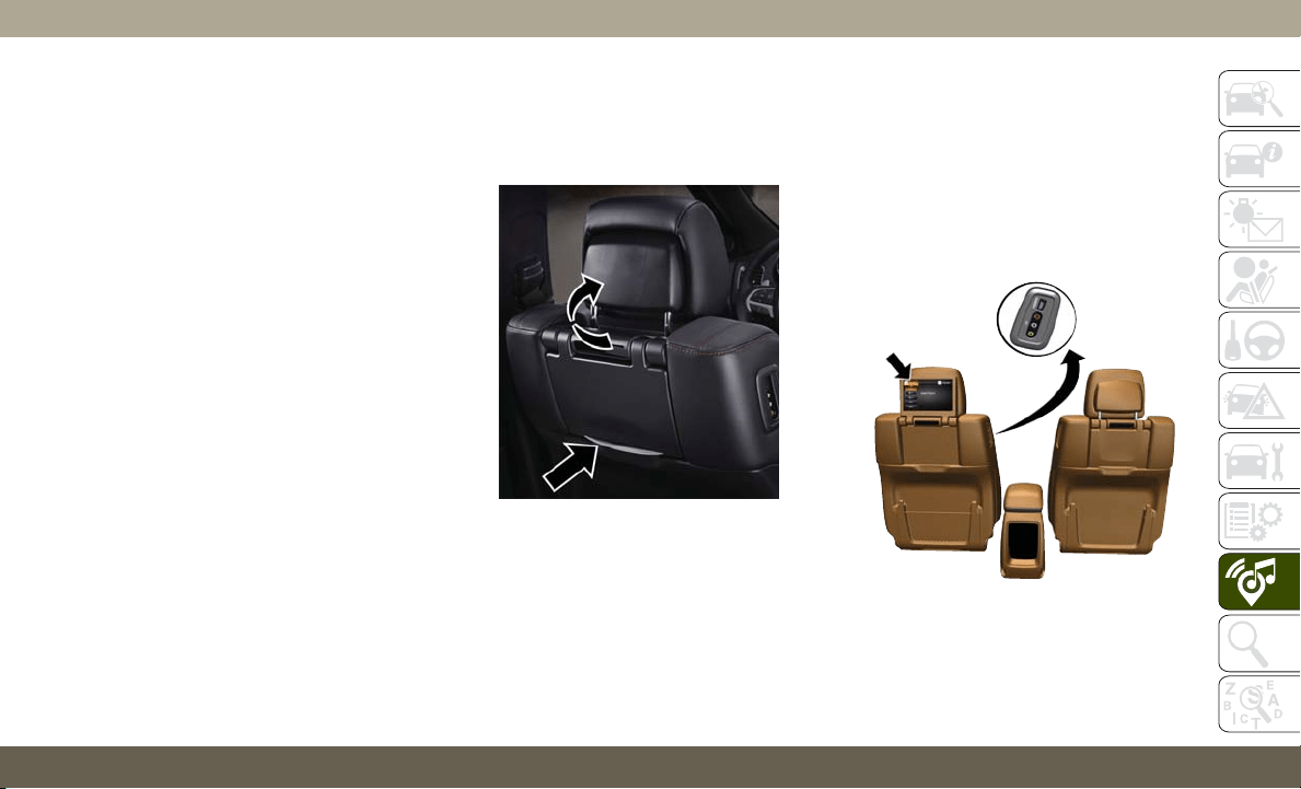
Bluetooth Streaming Audio
If using a Bluetooth equipped device you may
also be able to stream music to your vehicle's
sound system. Your connected device must
be Bluetooth compatible and paired with your
system (see Uconnect Phone for pairing in-
structions). You can access the music from
your connected Bluetooth device by pressing
the “Bluetooth” button on the touchscreen
while in Media mode.
UCONNECT REAR SEAT
ENTERTAINMENT (RSE)
SYSTEM — IF EQUIPPED
Your Rear Seat Entertainment System is de-
signed to give your family years of enjoyment.
You can play your favorite CDs, DVDs or
Blu-ray Discs, listen to audio over the wire-
less headphones, or plug and play a variety of
standard video games or audio devices.
Getting Started
• Screen(s) located in the rear of front seats:
Open the LCD screen cover by lifting up on
the cover.
•
Place the ignition in the ON or ACC position.
• Your vehicle may be equipped with a Blu-
ray disc player. If equipped with a Blu-ray
disc player, the icon will be present on the
player.
• Turn on the Rear Seat Entertainment sys-
tem by pushing the power button on the
remote control.
• When the Video Screen(s) are open and a
DVD/Blu-ray disc is inserted into the disc
player, the screen(s) turn(s) on automati-
cally, the headphone transmitters turn on
and playback begins.
RSE System Screen
RSE System Channel 1 (Rear 1)
305
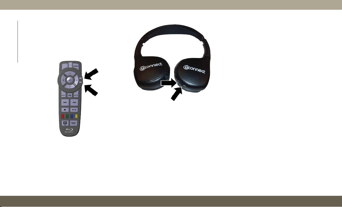
• With the Dual Video Screen System, Chan-
nel 1 (Rear 1) on the remote control and
headphones, refers to Screen 1 (driver's
side) and Channel 2 (Rear 2) on the Re-
mote Control and Headphones refers to
Screen 2 (passenger side).
• The system can be controlled either by the
front seat occupants utilizing the touch-
screen radio or by the rear seat occupants
using the remote control.
Dual Video Screen
NOTE:
Typically there are two different ways to op-
erate the features of the Rear Seat Entertain-
ment System.
• The Remote Control
• The Touchscreen Radio (If Equipped)
Blu-ray Disc Player
Play A Blu-ray Disc
The Blu-ray disc player is located in the
center console.
RSE System Remote Control Channel
Selectors
RSE System Headphone Channel
Selectors
MULTIMEDIA
306
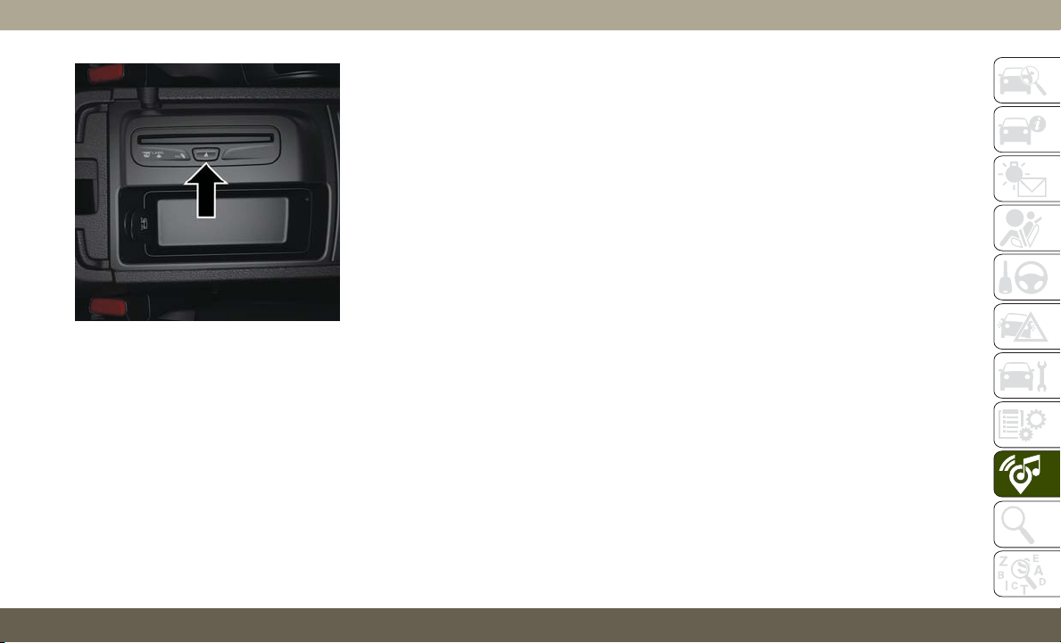
1. Insert a Blu-ray disc into the VES disc
player with the label facing as indicated
on the Blu-ray player. The radio automati-
cally selects the appropriate mode after
the disc is recognized and displays the
menu screen, the language screen, or
starts playing the first track.
2. To watch a Blu-ray disc on Rear 1 for
driver's side rear passengers, ensure the
Remote Control and Headphone switch is
on Rear 1.
3. To watch a Blu-ray disc on Rear 2 for
passenger side rear passengers, ensure
the Remote Control and Headphone
switch is on Rear 2.
NOTE:
• To view a Blu-ray disc on the radio, press
the “Media” button on the touchscreen,
and then press the “Disc” button. Press the
“Play” button, and then the “full screen”
button.
• Viewing a Blu-ray disc on the radio screen is
not available in all states/provinces. The
vehicle must be stopped, and the gear se-
lector must be in the PARK position for
vehicles with automatic transmission.
Blu-ray Disc Player Location
307
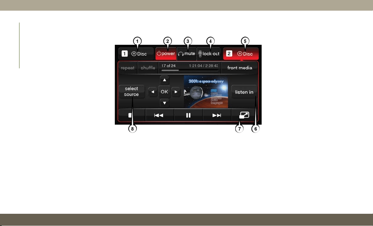
Using The Touchscreen Radio
Rear Media Control Screen
MULTIMEDIA
308

1. RSE Channel 1 Mode
Indicates the current source for Screen
1/Channel 1. This button will be high-
lighted when it is the active Screen/
Channel being controlled by the front
user. If this button is not highlighted,
select button to access controls for
Screen 1/Channel 1 source.
2. RSE Power
Press to turn RSE On/Off.
3. RSE Mute
Mute rear headphones for the current
ignition cycle. Pressing mute again will
unmute rear headphones.
4. RSE Remote Control Lock Out
Press to enable/disable remote control
functions.
5. RSE Channel 2 Mode
Indicates the current source for Screen
2/Channel 2. This button will be high-
lighted when it is the active Screen/
Channel being controlled by the front
user. If this button is not highlighted,
select button to access controls for
Screen 2/Channel 2 source.
6. Cabin Audio Mode
Select this button to change the cabin
audio to the rear entertainment source
currently shown on the rear media control
screen.
7. Radio Full Screen Mode
Select this button to change to Full
Screen Mode.
8. RSE Mode
Select this button to change source for
the active (highlighted) rear Screen/
Channel on the rear media control screen.
• Press the Media button on the touchscreen,
and then press the rear media button on the
touchscreen.
• Press the OK button on the touchscreen to
begin playing the Blu-ray disc on the touch-
screen radio.
Using The Remote Control
• Select an audio channel (Rear 1 for driver’s
side rear screen and Rear 2 for passenger’s
side rear screen), and then press the source
key, and using the up and down arrows,
highlight disc from the menu and press the
OK button.
• Press the popup/menu key to navigate the
disc menu and options.
309
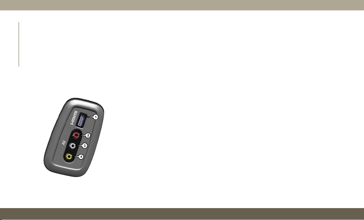
Play Video Games
Connect the video game console to the Audio/
Video RCA/HDMI input jacks located on the
side of each seat.
Audio/Video RCA/HDMI Jacks (AUX/HDMI
Jacks) on the side of each seat enable the
monitor to display video directly from a video
camera, connect video games for display
on the screen, or play music directly from an
MP3 player.
When connecting an external source to the
AUX/HDMI input, ensure to follow the stan-
dard color coding for the audio/video jacks:
1. HDMI Input.
2. Right audio in (red).
3. Left audio in (white).
4. Video in (yellow).
NOTE:
Certain high-end video games consoles may
exceed the power limit of the vehicle's Power
Inverter.
Accessibility — If Equipped
Accessibility is a feature of the DVD/Blu-ray
system that announces a function prior to
performing the action. For further informa-
tion refer to “Uconnect Settings” in “Multi-
media” in your Owner’s Manual.
Audio/Video RCA/HDMI Input Jacks
MULTIMEDIA
310
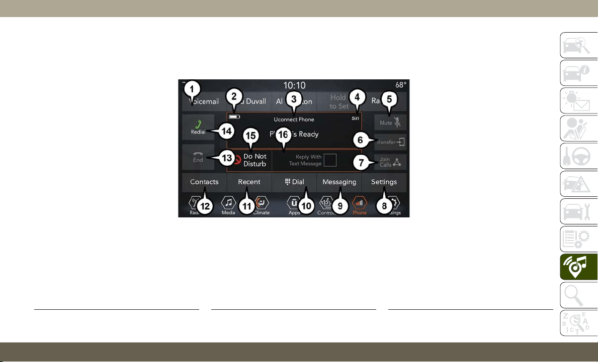
UCONNECT PHONE
Uconnect Phone (Bluetooth Hands Free Calling)
Uconnect 4 With 7–inch Display Radio Phone Menu
1 — Favorite Contacts
2 — Mobile Phone Battery Life
3 — Currently Paired Mobile Phone
4 — Siri
5 — Mute Microphone
6 — Transfer To/From Uconnect System
7 — Conference Call*
8 — Phone Settings
9 — Text Messaging**
10 — Direct Dial Pad
11 — Recent Call Log
12 — Browse Phone Book Entries
13 — End Call
14 — Call/Redial/Hold
15 — Do Not Disturb
16 — Reply with Text Message
* — Conference call feature only available
on GSM mobile devices
** — Text messaging feature not available
on all mobile phones (requires Bluetooth
MAP profile)
311
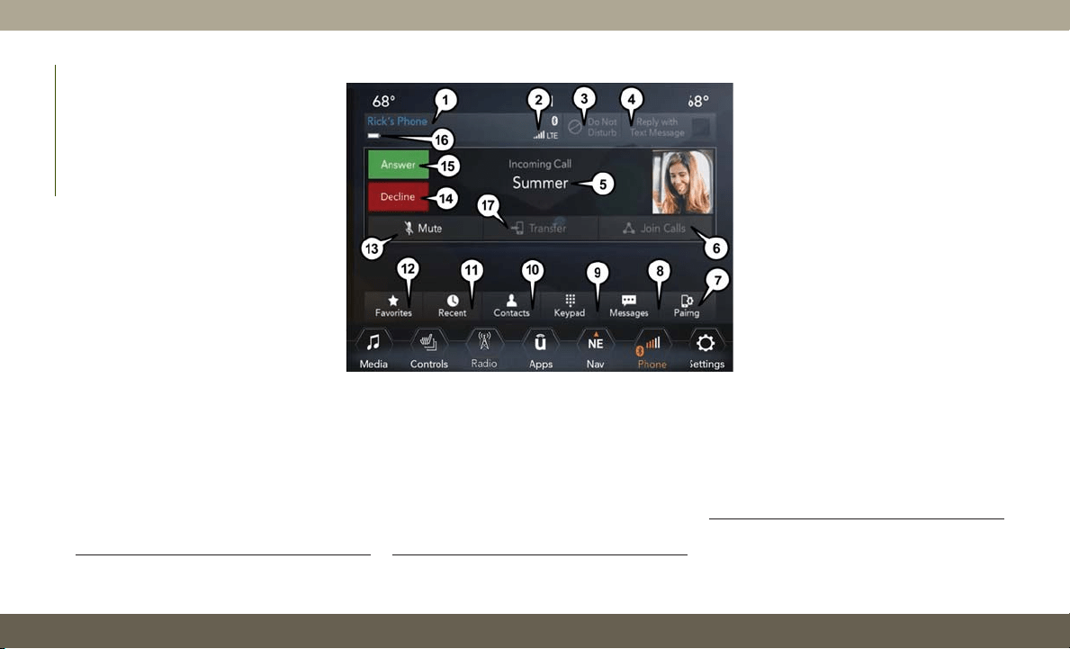
Uconnect 4C/4C NAV Phone Menu
1 — Currently Paired Mobile Phone
2 — Mobile Phone Signal Strength
3 — Do Not Disturb
4 — Reply with Text Message
5 — Current Phone Contact’s Name
6 — Conference Call*
7 — Phone Pairing
8 — Text Messaging Menu**
9 — Direct Dial Pad
10 — Contact Menu
11 — Recent Call Log
12 — Favorite Contacts
13 — Mute Microphone
14 — Decline Incoming Call
15 — Answer/Redial/Hold
16 — Mobile Phone Battery Life
17 — Transfer To/From Uconnect System
* — Conference call feature only available
on GSM mobile devices
** — Text messaging feature not available
on all mobile phones (requires Bluetooth
MAP profile)
MULTIMEDIA
312
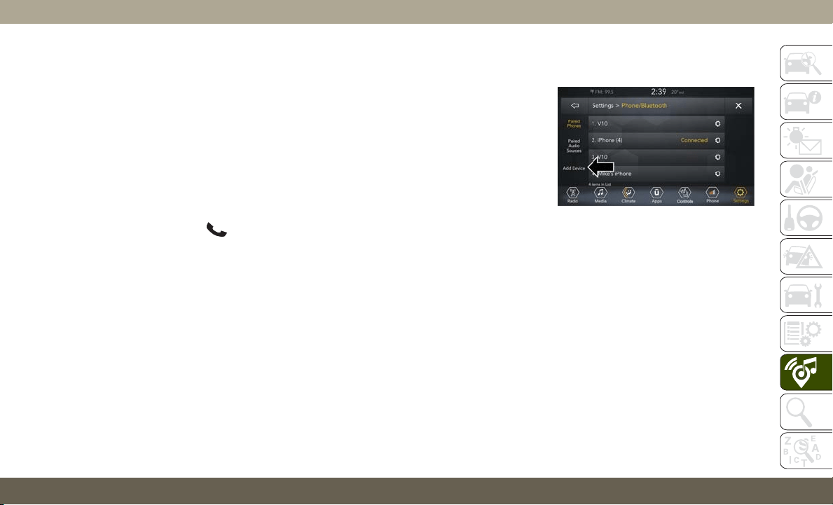
The Uconnect Phone feature enables you to
place and receive hands-free mobile phone
calls. Drivers can also place mobile phone
calls using their voice or by using the buttons
on the touchscreen (see Voice Command sec-
tion).
The hands-free calling feature is made pos-
sible through Bluetooth technology — the
global standard that enables different elec-
tronic devices to connect to each other wire-
lessly.
If the Uconnect Phone Button
exists on
your steering wheel, you then have the
Uconnect Phone features.
NOTE:
• The Uconnect Phone requires a mobile
phone equipped with the Bluetooth Hands-
Free Profile, Version 1.0 or higher.
• Most mobile phones/devices are compat-
ible with the Uconnect system, however
some mobile phones/devices may not be
equipped with all of the required features to
utilize all of the Uconnect system features.
For Uconnect Customer Care:
• U.S. residents visit UconnectPhone.com or
call 1-877-855-8400.
•
Canadian residents visit UconnectPhone.com
or call 1-800-465-2001 (English) or
1-800-387-9983 (French).
Pairing (Wirelessly Connecting) Your
Mobile Phone To The Uconnect System
Mobile phone pairing is the process of estab-
lishing a wireless connection between a cel-
lular phone and the Uconnect system.
NOTE:
•
To use the Uconnect Phone feature, you first
must determine if your mobile phone and
software are compatible with the Uconnect
system. Please visit UconnectPhone.com
for
complete mobile phone compatibility infor-
mation.
• Mobile phone pairing is not available while
the vehicle is in motion.
• A maximum of ten mobile phones can be
paired to the Uconnect system.
Start Pairing Procedure On The Radio
Uconnect 4:
1. Place the ignition in the ACC or ON
position.
2. Press the “Phone” button.
3. Select “Settings.”
4. Select “Paired Phones.”
5. Select “Add device.”
• Uconnect Phone will display an “In
progress” screen while the system is
connecting.
Uconnect 4 Add Device
313
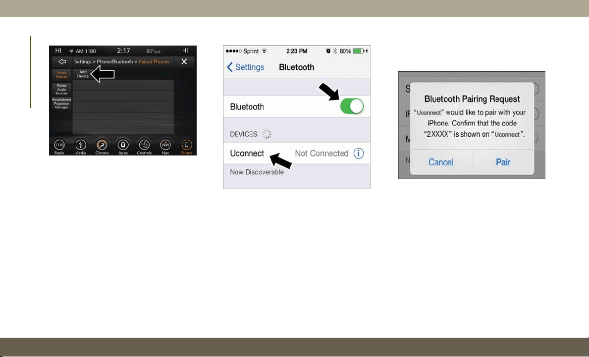
Uconnect 4C/4C NAV:
1. Place the ignition in the ACC or ON
position.
2. Press the “Phone” button in the Menu Bar
on the touchscreen.
3. Select “Pairing.”
4. Select “Paired Phones.”
5. Select “Add device.”
• Uconnect Phone will display an “In
progress” screen while the system is
connecting.
Pair Your iPhone:
To search for available devices on your
Bluetooth enabled iPhone:
1. Press the Settings button.
2. Select Bluetooth.
•
Ensure the Bluetooth feature is enabled.
Once enabled, the mobile phone will be-
gin to search for Bluetooth connections.
3. When your mobile phone finds the
Uconnect system, select “Uconnect”.
Complete The iPhone Pairing Procedure:
When prompted on the mobile phone, accept
the connection request from Uconnect
Phone.
NOTE:
Some mobile phones will require you to enter
the PIN number.
Uconnect 4C/4C NAV Add Device
Bluetooth On/Uconnect Device
Pairing Request
MULTIMEDIA
314
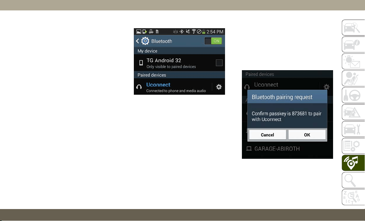
Select The iPhone's Priority Level
When the pairing process has successfully
completed, the system will prompt you to
choose whether or not this is your favorite
mobile phone. Selecting “Yes” will make this
mobile phone the highest priority. This mo-
bile phone will take precedence over other
paired mobile phones within range and will
connect to the Uconnect system automati-
cally when entering the vehicle. Only one
mobile phone and/or one Bluetooth audio
device can be connected to the Uconnect
system at a time. If “No” is selected, simply
select “Uconnect” from the mobile phone/
audio device Bluetooth screen, and the
Uconnect system will reconnect to the
Bluetooth device.
Pair Your Android Device:
To search for available devices on your Bluetooth
enabled Android Device:
1. Push the Menu button.
2. Select Settings.
3. Select Connections.
4. Turn Bluetooth setting to “On.”
•
Ensure the Bluetooth feature is enabled.
Once enabled, the mobile phone will be-
gin to search for Bluetooth connections.
5. Once your mobile phone finds the
Uconnect system, select “Uconnect”.
• You may be prompted by your mobile
phone to download the phonebook,
check “Do Not Ask Again” to automati-
cally download the phonebook. This is
so you can make calls by saying the
name of your contact.
Complete The Android Pairing Procedure:
Confirm the passkey shown on the mobile
phone matches the passkey shown on the
Uconnect system then accept the Bluetooth
pairing request.
Uconnect Device
Pairing Request
315

NOTE:
Some mobile phones require the PIN to be
entered manually, enter the PIN number
shown on the Uconnect screen.
Select The Android Mobile Phone's Priority
Level
When the pairing process has successfully
completed, the system will prompt you to
choose whether or not this is your favorite
mobile phone. Selecting “Yes” will make this
mobile phone the highest priority. This mo-
bile phone will take precedence over other
paired mobile phones within range and will
connect to the Uconnect system automati-
cally when entering the vehicle. Only one
mobile phone and/or one Bluetooth audio
device can be connected to the Uconnect
system at a time. If “No” is selected, simply
select “Uconnect” from the mobile phone/
audio device Bluetooth screen, and the
Uconnect system will reconnect to the
Bluetooth device.
NOTE:
Software updates, either on your phone or
Uconnect system, may interfere with the
Bluetooth connection. If this happens, sim-
ply repeat the pairing process. However, first,
make sure to delete the device from the list of
phones on your Uconnect system. Next, be
sure to remove Uconnect from the list of
devices in your phone’s Bluetooth settings.
You are now ready to make hands-free calls.
Push the Uconnect “Phone” button
on
your steering wheel to begin.
NOTE:
Refer to UconnectPhone.com website for ad-
ditional information on mobile phone pairing
and for a list of compatible phones.
Common Phone Commands (Examples)
• “Call John Smith”
• “Call John Smith mobile”
• “Dial 1 248 555 1212”
• “Redial”
Mute (Or Unmute) Microphone During
Call
• During a call, press the “Mute” button on
the Phone main screen to mute and un-
mute the call.
Transfer Ongoing Call Between Handset
And Vehicle
• During an on-going call, press the “Trans-
fer” button on the Phone main screen to
transfer an on-going call between handset
and vehicle.
Phonebook
The Uconnect system will automatically sync
your phonebook from your paired phone, if
this feature is supported by your phone.
Phonebook contacts are updated each time
that the phone is connected. If your phone
book entries do not appear, check the set-
tings on your phone. Some phones require
you to enable this feature manually.
MULTIMEDIA
316
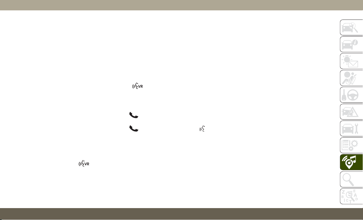
• Your phonebook can be browsed on the
Uconnect system touchscreen, but editing
can only be done on your phone. To browse,
press the “Phone” button on the touch-
screen, then the “Phonebook” button on
the touchscreen.
Favorite phonebook entries can be saved as
Favorites for quicker access. Favorites are
shown at the top of the main phone screen.
Voice Command Tips
• Speaking complete names (i.e; Call John
Doe vs. Call John) will result in greater
system accuracy.
• You can “link” commands together for
faster results. Say “Call John Doe, mobile,”
for example.
• If you are listening to available voice com-
mand options, you do not have to listen to
the entire list. When you hear the command
that you need, push the
button on the
steering wheel, wait for the beep and say
your command.
Changing The Volume
• Use the radio VOLUME rotary knob to ad-
just the volume to a comfortable level while
the Uconnect system is speaking.
NOTE:
The volume setting for Uconnect is different
than the audio system.
• Start a dialogue by pushing the VR button
, then say a command. For example,
"Help".
NOTE:
To access help, push the Uconnect VR button
(if active) on the steering wheel and say,
"Help." Push the Uconnect VR Pickup button
(if active) or the VR button
(if active)
and say, "Cancel" to cancel the help session.
Using Do Not Disturb
With Do Not Disturb, you can disable notifi-
cations from incoming calls and texts, allow-
ing you to keep your eyes on the road and
hands on the wheel. For your convenience,
there is a counter display to keep track of your
missed calls and text messages while you
were using Do Not Disturb.
Do Not Disturb can automatically reply with a
text message, a call, or both, when declining
an incoming call and send it to voicemail.
Automatic reply messages can be:
• “I am driving right now, I will get back to
you shortly.”
• Create a custom auto reply message up to
160 characters.
While in Do Not Disturb, Conference Call can
be selected so you can still place a second
call without being interrupted by incoming
calls.
NOTE:
• Only the beginning of your custom message
will be seen on the touchscreen.
• Reply with text message is not compatible
with iPhones.
•
Auto reply with text message is only available
on phones that support Bluetooth MAP.
317
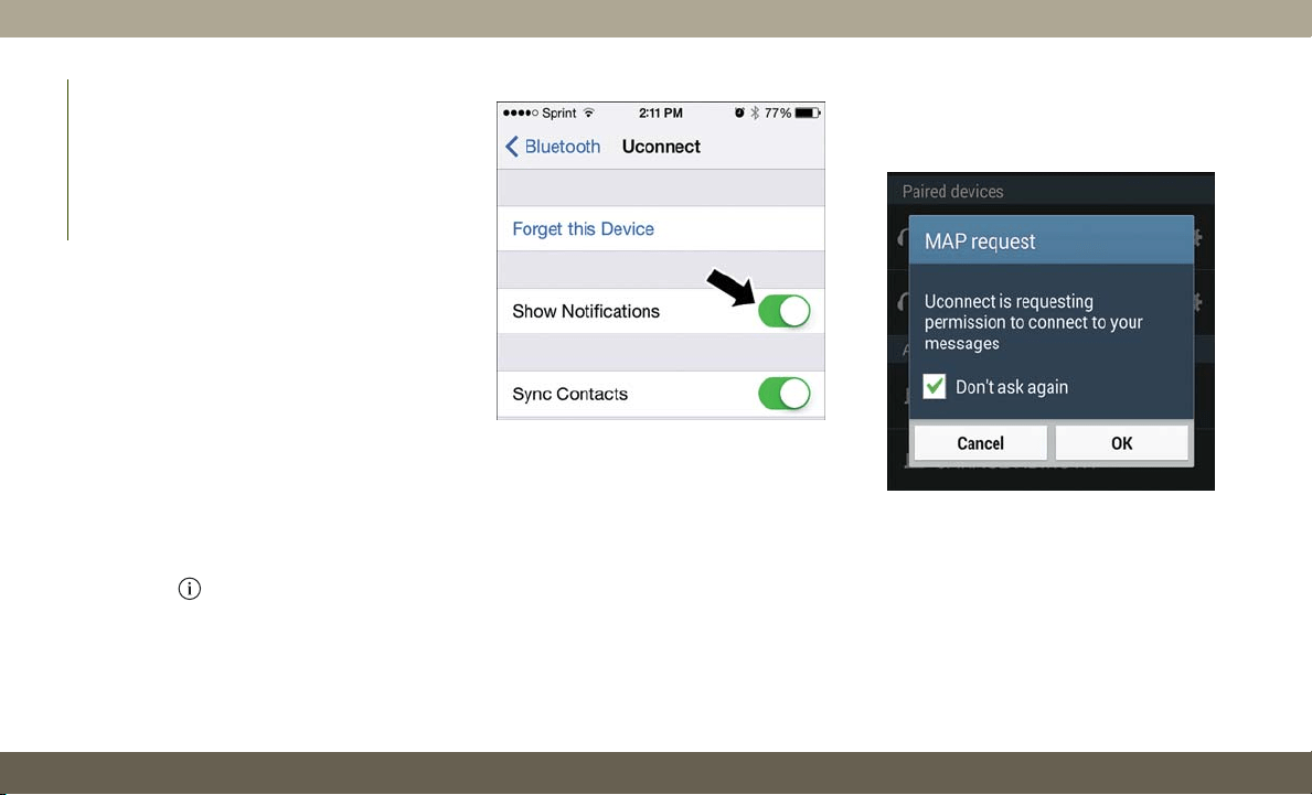
Incoming Text Messages
After pairing your Uconnect system with a
Bluetooth enabled mobile device with the
Message Access Profile (MAP), the Uconnect
system can announce a new incoming text
message and read it to you over the vehicle’s
audio system.
NOTE:
Only incoming text messages received during
the current ignition cycle can be viewed/read.
To enable incoming text messaging:
iPhone
1. Press the settings button on the mobile
phone.
2. Select Bluetooth.
• Ensure Bluetooth is enabled, and the
mobile phone is paired to the
Uconnect system.
3. Select
located under DEVICES next to
Uconnect.
4. Turn “Show Notifications” to on.
Android Devices
1. Press the Menu button on the mobile
phone.
2. Select “Settings.”
3. Select “Connections.”
4. Turn “Show Notifications” to on.
• A pop up will appear asking you to
accept a request for permission to con-
nect to your messages. Select “Don’t
ask again” and press OK.
NOTE:
All incoming text messages received during
the current ignition cycle will be deleted from
the Uconnect system when the ignition is
turned to the OFF position.
Enable iPhone Incoming Text Messages
Enable Android Device Incoming Text
Messages
MULTIMEDIA
318

Helpful Tips And Common Questions To
Improve Bluetooth Performance With
Your Uconnect System
Mobile Phone won’t reconnect to system after
pairing:
• Set mobile phone to auto-connect or
trusted device in mobile phone Bluetooth
settings (Blackberry devices).
• Perform a factory reset on your mobile
phone. Refer to your mobile phone manu-
facturer or cellular provider for instruc-
tions.
• Many mobile phones do not automatically
reconnect after being restarted (hard re-
boot). Your mobile phone can still be con-
nected manually. Close all applications that
may be operating (refer to mobile phone
manufacturer’s instructions), and follow
“Pairing (Wirelessly Connecting) Your Mo-
bile Phone To The Uconnect System”.
Mobile Phone won’t pair to system:
• Perform a hard reset in the mobile phone by
removing the battery (if removable — see
your mobile phone’s owner manual).
• Delete pairing history in mobile phone and
Uconnect system; usually found in phone’s
Bluetooth connection settings.
• Verify you are selecting “Uconnect” in the
discovered Bluetooth devices on your mo-
bile phone.
• If your vehicle system generates a pin code
the default is 0000.
Mobile Phonebook didn’t download:
• Check “Do not ask again,” then accept the
“phonebook download” request on your
mobile phone.
• Up to 5,000 contact names with four num-
bers per contact will transfer to the
Uconnect 4C/4C NAV system phonebook.
Can’t make a conference call:
• CDMA (Code-Division Multiple Access) car-
riers do not support conference calling.
Refer to your mobile phone user’s manual
for further information.
Making calls while connected to AUX:
• Plugging in your mobile phone to AUX while
connected to Bluetooth will disable Hands-
Free Calling. Do not make calls while your
mobile phone is plugged into the AUX jack.
319
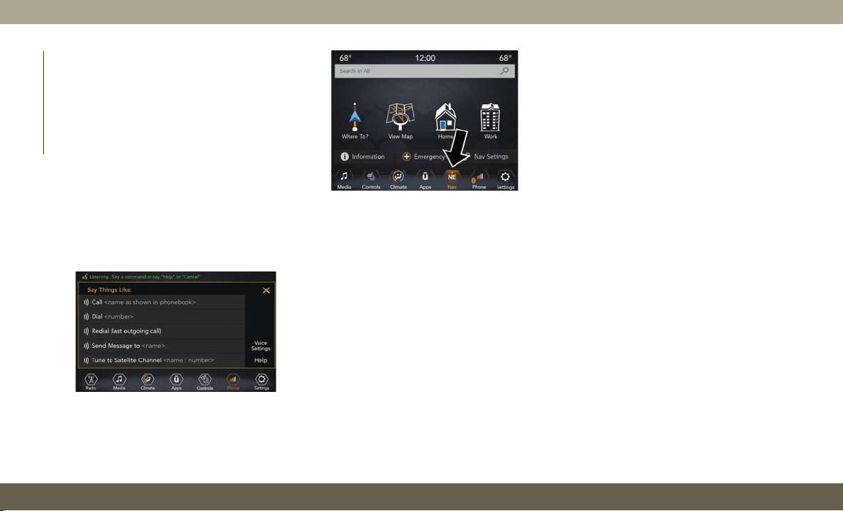
UCONNECT VOICE
RECOGNITION QUICK TIPS
Introducing Uconnect
Start using Uconnect Voice Recognition with
these helpful quick tips. It provides the key
Voice Commands and tips you need to know
to control your Uconnect 4, or Uconnect
4C/4C NAV system.
Start using Uconnect Voice Recognition with
these helpful quick tips. It provides the key
Voice Commands and tips you need to know
to control your Uconnect 4C/4C NAV system.
If you see the NAV icon on the bottom bar, or
in the Apps menus, of your 8.4-inch touch-
screen, you have the Uconnect 4C NAV sys-
tem. If not, you have a Uconnect 4C with
8.4-inch display system.
Get Started
All you need to control your Uconnect system
with your voice are the buttons on your steer-
ing wheel.
Helpful hints for using Voice Recognition:
• Visit UconnectPhone.com to check mobile
device and feature compatibility and to find
phone pairing instructions.
• Reduce background noise. Wind and pas-
senger conversations are examples of noise
that may impact recognition.
• Speak clearly at a normal pace and volume
while facing straight ahead. The micro-
phone is positioned on the rearview mirror
and aimed at the driver.
• Each time you give a Voice Command, you
must first push either the Voice Recogni-
tion (VR) or Phone button, wait until after
the beep, then say your Voice Command.
• You can interrupt the help message or sys-
tem prompts by pushing the VR or Phone
button and saying a Voice Command from
the current category.
Uconnect 4
Uconnect 4C/4C NAV
MULTIMEDIA
320
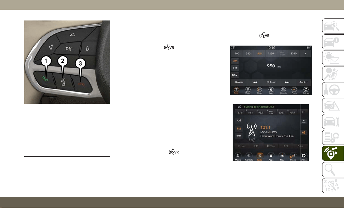
Basic Voice Commands
The basic Voice Commands below can be given
at any point while using your Uconnect system.
P
ush the VR button .
After the beep, say:
•“Cancel” to stop a current voice session
•“Help” to hear a list of suggested Voice
Commands
•“Repeat” to listen to the system prompts
again
Notice the visual cues that inform you of your
voice recognition system’s status. Cues ap-
pear on the touchscreen.
Radio
Use your voice to quickly get to the AM, FM or
SiriusXM Satellite Radio stations you would
like to hear. (Subscription or included
SiriusXM Satellite Radio trial required.)
Push the VR button
. After the beep,
say:
•“Tune to ninety-five-point-five FM”
•“Tune to Satellite Channel Hits 1”
TIP: At any time, if you are not sure of what to
say or want to learn a Voice Command, push
the VR button
and say “Help.” The
system provides you with a list of commands.
Uconnect Voice Command Buttons
1 — Push To Initiate Or To Answer A
Phone Call, Send Or Receive A Text
2 — For All Radios: Push To Begin
Radio, Media, Or Climate Functions.
For 8.4–inch System Only: Push To
Begin Navigation Function
3 — Push To End Call
Uconnect 4 Radio
Uconnect 4C/4C NAV Radio
321
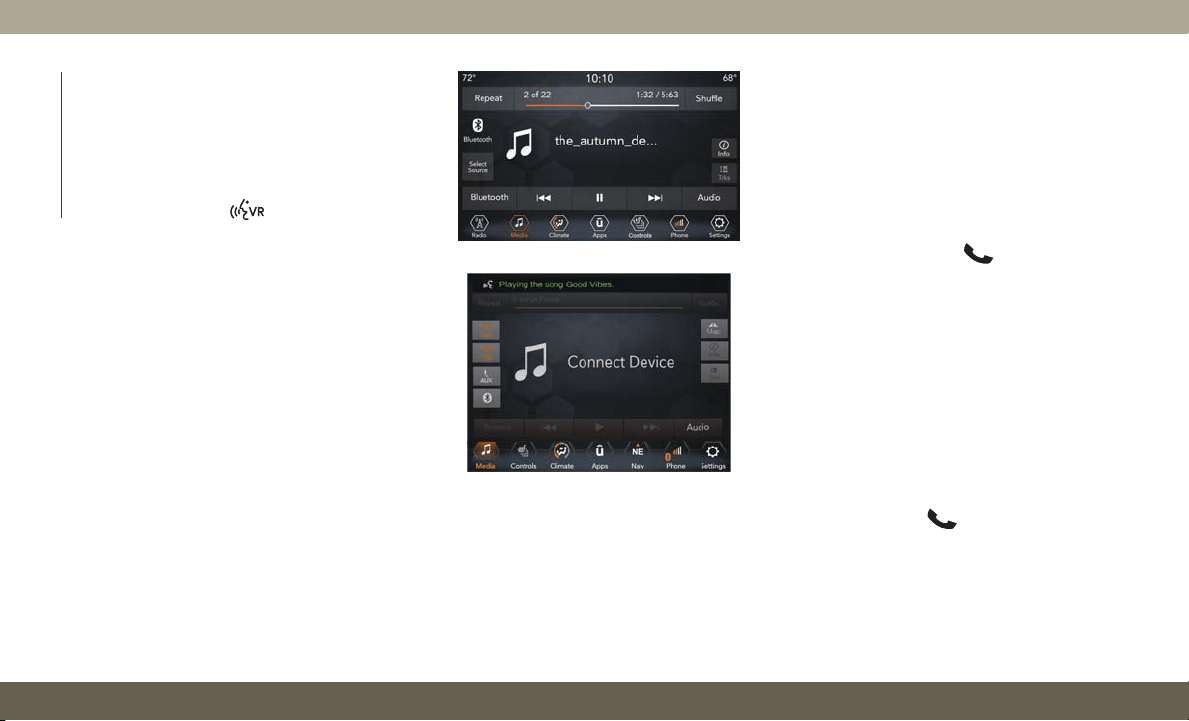
Media
Uconnect offers connections via USB,
Bluetooth and auxiliary ports (If Equipped).
Voice operation is only available for con-
nected USB and AUX devices.
Push the VR button
. After the beep, say
one of the following commands and follow
the prompts to switch your media source or
choose an artist.
•“Change source to Bluetooth”
•“Change source to AUX”
•“Change source to USB”
•“Play artist Beethoven”; “Play album Great-
est Hits”; “Play song Moonlight Sonata”;
“Play genre Classical”
TIP: Press the Browse button on the touch-
screen to see all of the music on your USB
device. Your Voice Command must match
exactly how the artist, album, song and genre
information is displayed.
Phone
Making and answering hands-free phone
calls is easy with Uconnect. When the Phone-
book button is illuminated on your touch-
screen, your system is ready. Check
UconnectPhone.com for mobile phone com-
patibility and pairing instructions.
Push the Phone button
. After the beep,
say one of the following commands:
•“Call John Smith”
•“Dial 123-456-7890 and follow the system
prompts”
•“Redial (call previous outgoing phone num-
ber)”
•“Call back (call previous incoming phone
number)”
TIP: When providing a Voice Command, push
the Phone button
and say “Call,” then
pronounce the name exactly as it appears in
your phone book. When a contact has mul-
tiple phone numbers, you can say “Call John
Smith work.”
Uconnect 4 Media
Uconnect 4C/4C NAV Media
MULTIMEDIA
322
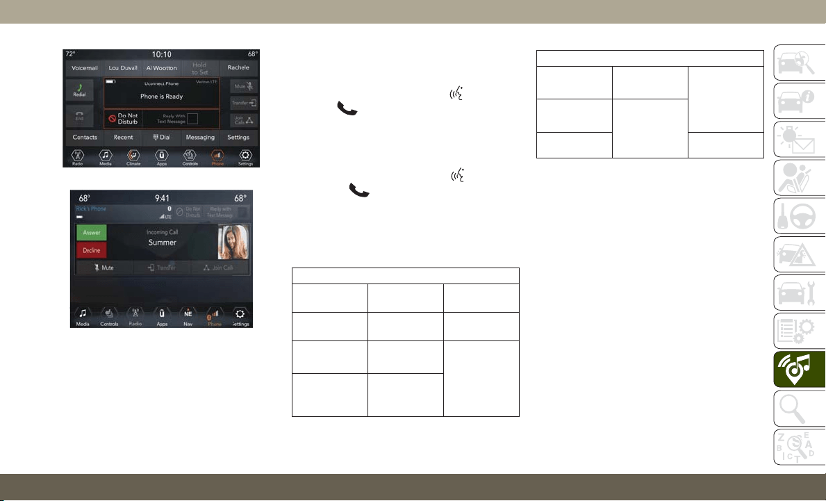
Voice Text Reply — If Equipped
Uconnect announces incoming text mes-
sages. Push the VR button
or Phone
button
(if enabled) and say “Listen.”
(Must have compatible mobile phone paired
to Uconnect system.)
1. Once an incoming text message is read to
you, push the VR button
or Phone
button
(if enabled). After the beep,
say: “Reply.”
2. Listen to the Uconnect prompts. After the
beep, repeat one of the pre-defined mes-
sages and follow the system prompts.
PRE-DEFINED VOICE TEXT REPLY RESPONSES
Yes.
Stuck in
traffic.
See you later.
No.
Start without
me.
I’ll be late.
Okay.
Where are
you?
I will be 5
<or 10, 15,
20, 25, 30,
45, 60>
minutes late.
Call me.
Are you there
yet?
PRE-DEFINED VOICE TEXT REPLY RESPONSES
I’ll call you
later.
I need direc-
tions.
See you in 5
<or 10, 15,
20, 25, 30,
45, 60>
minutes.
I’m on my
way.
Can’t talk
right now.
I’m lost. Thanks.
NOTE:
Only use the numbering listed, otherwise
the system does not transpose the mes-
sage.
TIP:
Your mobile phone must have the full
implementation of the
Message Access Profile
(MAP)
to take advantage of this feature. For
details about MAP, visit
UconnectPhone.com.
Uconnect 4 Phone
Uconnect 4C/4C NAV Phone
323
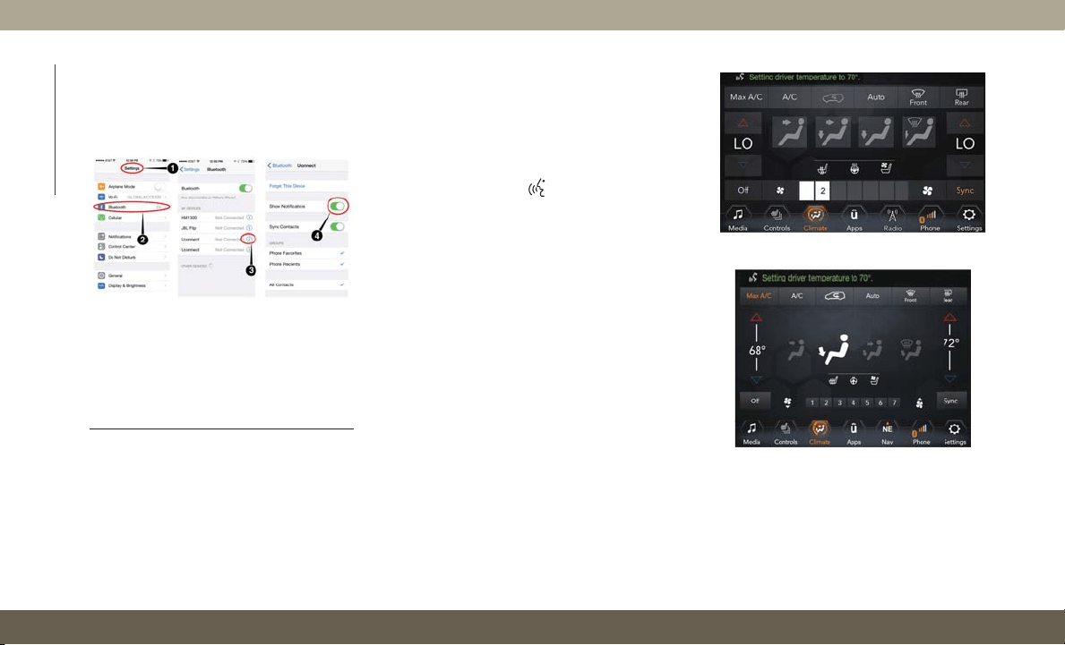
Apple iPhone iOS 6 or later supports reading
incoming text messages only. To enable this
feature on your Apple iPhone, follow these
four simple steps:
TIP: Voice Text Reply is not compatible with
iPhone, but if your vehicle is equipped with
Siri Eyes Free, you can use your voice to send
a text message.
Climate
Too hot? Too cold? Adjust vehicle tempera-
tures hands-free and keep everyone comfort-
able while you keep moving ahead. (If vehicle
is equipped with climate control.)
Push the VR button
. After the beep, say
one of the following commands:
•“Set the driver temperature to 70 degrees”
•“Set the passenger temperature to 70
degrees”
TIP: Voice Command for Climate may only be
used to adjust the interior temperature of
your vehicle. Voice Command will not work to
adjust the heated seats or steering wheel if
equipped.
iPhone Notification Settings
1 — Select “Settings”
2 — Select “Bluetooth”
3
— Select The (i) For The Paired Vehicle
4 — Turn On “Show Notifications”
Uconnect 4 With 7-inch Display Climate
Uconnect 4C/4C NAV With 8.4-Inch
Display Climate
MULTIMEDIA
324
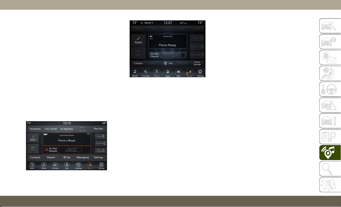
Siri Eyes Free — If Equipped
Siri lets you use your voice to send text
messages, select media, place phone calls
and much more. Siri uses your natural lan-
guage to understand what you mean and
responds back to confirm your requests. The
system is designed to keep your eyes on the
road and your hands on the wheel by letting
Siri help you perform useful tasks.
To enable Siri, push and hold, then release
the Uconnect Voice Recognition (VR) button
on the steering wheel. After you hear a double
beep you can ask Siri to play podcasts and
music, get directions, read text messages and
many other useful requests.
Do Not Disturb
With Do Not Disturb, you can disable notifi-
cations from incoming calls and texts, allow-
ing you to keep your eyes on the road and
hands on the wheel. For your convenience,
there is a counter display to keep track of your
missed calls and text messages while you
were using Do Not Disturb.
Do Not Disturb can automatically reply with a
text message, a call or both, when declining
an incoming call and send it to voicemail.
Automatic reply messages can be:
• “I am driving right now, I will get back to
you shortly.”
• Create a custom auto reply message up to
160 characters.
NOTE:
Only the first 25 characters can be seen on
the touchscreen while typing a custom
message.
While in Do Not Disturb, Conference Call can
be selected so you can still place a second
call without being interrupted by incoming
calls.
NOTE:
• Reply with text message is not compatible
with iPhones.
• Auto reply with text message is only avail-
able on phones that support Bluetooth
MAP.
Uconnect 4 Siri Eyes Free Available
Uconnect 4C/4C NAV With 8.4–inch Siri
Eyes Free Available
325
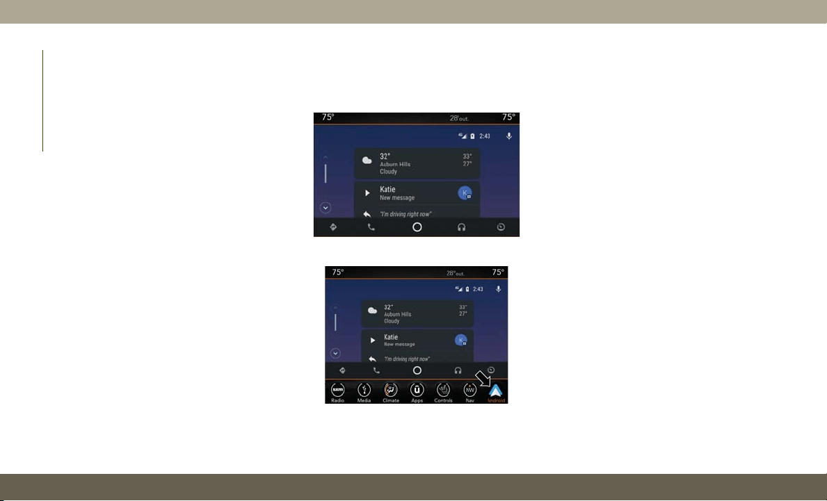
Android Auto — If Equipped
NOTE:
Feature availability depends on your carrier
and mobile phone manufacturer. Some
Android Auto features may or may not be
available in every region and/or language.
Android Auto allows you to use your voice to
interact with Android’s best-in-class speech
technology through your vehicle’s voice rec-
ognition system, and use your smartphone’s
data plan to project your Android powered
smartphone and a number of its apps onto
your Uconnect touchscreen. Connect your
Android 5.0 (Lollipop), or higher, to one of
the media USB ports, using the factory-
provided USB cable, and press the new
Android Auto icon that replaces your
“Phone” icon on the main menu bar to begin
Android Auto. Push and hold the VR button
on the steering wheel, or press and hold the
“Microphone” icon within Android Auto, to
activate Android’s VR, which recognizes
natural voice commands, to use a list of your
smartphone’s features:
• Maps
• Music
• Phone
• Text Messages
• Additional Apps
Refer to your Uconnect Owner’s Manual
Supplement for further information.
NOTE:
Requires compatible smartphone running
Android 5.0 Lollipop or higher and download
app on Google Play. Android, Android Auto,
and Google Play are trademarks of Google Inc.
Apple CarPlay — If Equipped
NOTE:
Feature availability depends on your carrier
and mobile phone manufacturer. Some Apple
CarPlay features may or may not be available
in every region and/or language.
Apple CarPlay allows you to use your voice to
interact with Siri through your vehicle’s voice
recognition system, and use your smart-
phone’s data plan to project your iPhone and
a number of its apps onto your Uconnect
touchscreen. Connect your iPhone 5, or
higher, to one of the media USB ports, using
the factory-provided Lightning cable, and
press the new CarPlay icon that replaces your
“Phone” icon on the main menu bar to begin
Android Auto On 7-inch Display
Android Auto On 8.4-inch Display
MULTIMEDIA
326
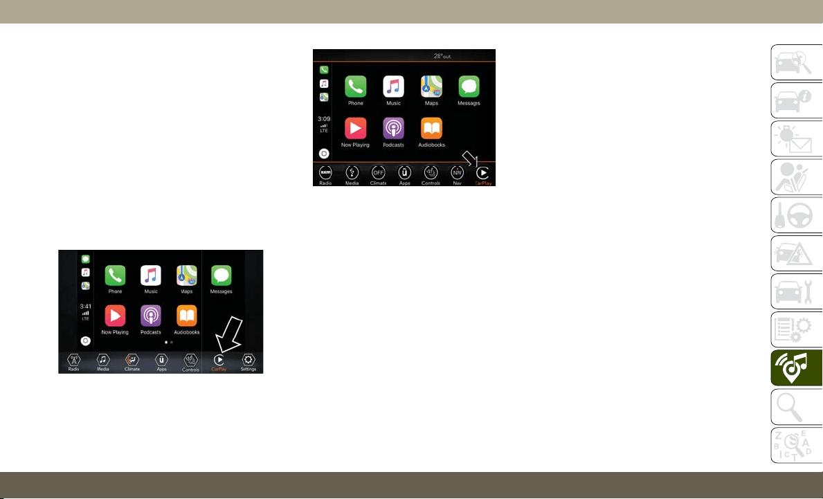
Apple CarPlay. Push and hold the VR button
on the steering wheel, or press and hold the
“Home” button within Apple CarPlay, to ac-
tivate Siri, which recognizes natural voice
commands to use a list of your iPhone’s
features:
• Phone
• Music
• Messages
• Maps — if equipped
• Additional Apps — if equipped
Refer to your Uconnect Owner’s Manual
Supplement for further information.
NOTE:
Requires compatible iPhone. See dealer for
phone compatibility. Data plan rates apply.
Vehicle user interface is a product of Apple.
Apple CarPlay is a trademark of Apple Inc.
iPhone is a trademark of Apple Inc., regis-
tered in the US and other countries. Apple
terms of use and privacy statements apply.
General Information
The following regulatory statement applies to
all Radio Frequency (RF) devices equipped in
this vehicle:
This device complies with Part 15 of the FCC
Rules and with Industry Canada license-
exempt RSS standard(s). Operation is sub-
ject to the following two conditions:
1. This device may not cause harmful inter-
ference, and
2. This device must accept any interference
received, including interference that may
cause undesired operation.
NOTE:
Changes or modifications not expressly ap-
proved by the party responsible for compli-
ance could void the user’s authority to oper-
ate the equipment.
Apple CarPlay On 7-inch Display
Apple CarPlay On 8.4-inch Display
327

Additional Information
© 2018 FCA US LLC. All rights reserved.
Mopar and Uconnect are registered trade-
marks and Mopar Owner Connect is a trade-
mark of FCA US LLC. Android is a trademark
of Google Inc. SiriusXM and all related marks
and logos are trademarks of SiriusXM Radio
Inc.
Uconnect System Support:
• U.S. residents visit
www.DriveUconnect.com or call:
1-877-855-8400 (24 hours a day 7 days
a week)
• Canadian residents visit
www.DriveUconnect.ca or call:
1-800-465-2001 (English) or
1-800-387-9983 (French)
SiriusXM Guardian services support:
• U.S. residents visit
www.siriusxm.com/guardian or call:
1-844-796-4827
• Canadian residents visit
www.siriusxm.ca/guardian or call:
1-877-324-9091
MULTIMEDIA
328

IF YOU NEED ASSISTANCE
The manufacturer and its authorized dealer
are vitally interested in your satisfaction. We
want you to be happy with our products and
services.
Warranty service must be done by an autho-
rized dealer. We strongly recommend that you
take the vehicle to an authorized dealer. They
know your vehicle the best, and are most
concerned that you get prompt and high qual-
ity service. The manufacturer's authorized
dealer have the facilities, factory-trained
technicians, special tools, and the latest in-
formation to ensure the vehicle is fixed cor-
rectly and in a timely manner.
This is why you should always talk to an
authorized dealer service manager first. Most
matters can be resolved with this process.
• If for some reason you are still not satisfied,
talk to the general manager or owner of the
authorized dealer. They want to know if you
need assistance.
• If an authorized dealer is unable to resolve
the concern, you may contact the manufac-
turer's customer center.
Any communication to the manufacturer's
customer center should include the following
information:
• Owner's name and address
•
Owner's telephone number (home and office)
• Authorized dealer name
• Vehicle Identification Number (VIN)
• Vehicle delivery date and mileage
FCA US LLC Customer Center
P.O. Box 21–8004
Auburn Hills, MI 48321–8004
Phone: (877) 426-5337
FCA Canada Inc. Customer Center
P.O. Box 1621
Windsor, Ontario N9A 4H6
Phone: (800) 465-2001 English / (800)
387-9983 French
In Mexico Contact
Av. Prolongacion Paseo de la Reforma, 1240
Sante Fe C.P. 05109
Mexico, D. F.
In Mexico City: 800-505-1300
Outside Mexico City: +(52)55 50817568
Puerto Rico And U.S. Virgin Islands
FCA Caribbean LLC
P.O. Box 191857
San Juan 00919-1857
Phone: (877) 426-5337
Fax: (787) 782-3345
329

Customer Assistance For The Hearing Or
Speech Impaired (TDD/TTY)
To assist customers who have hearing diffi-
culties, the manufacturer has installed spe-
cial TDD (Telecommunication Devices for the
Deaf) equipment at its customer center. Any
hearing or speech impaired customer, who
has access to a TDD or a conventional tele-
typewriter (TTY) in the United States, can
communicate with the manufacturer by dial-
ing 1-800-380-CHRY.
Canadian residents with hearing difficulties
that require assistance can use the special
needs relay service offered by Bell Canada.
For TTY teletypewriter users, dial 711 and for
Voice callers, dial 1-800-855-0511 to con-
nect with a Bell Relay Service operator.
Service Contract
You may have purchased a service contract
for a vehicle to help protect you from the high
cost of unexpected repairs after the manufac-
turer's New Vehicle Limited Warranty expires.
The manufacturer stands behind only the
manufacturer's service contracts. If you pur-
chased a manufacturer's service contract,
you will receive Plan Provisions and an Owner
Identification Card in the mail within three
weeks of the vehicle delivery date. If you have
any questions about the service contract, call
the manufacturer's Service Contract National
Customer Hotline at 1-800-521-9922 (Ca-
nadian residents, call (800) 465-2001 Eng-
lish / (800) 387-9983 French).
The manufacturer will not stand behind any
service contract that is not the manufactur-
er's service contract. It is not responsible for
any service contract other than the manufac-
turer's service contract. If you purchased a
service contract that is not a manufacturer's
service contract, and you require service after
the manufacturer's New Vehicle Limited War-
ranty expires, please refer to the contract
documents, and contact the person listed in
those documents.
We appreciate that you have made a major
investment when you purchased the vehicle.
An authorized dealer has also made a major
investment in facilities, tools, and training to
assure that you are absolutely delighted with
the ownership experience. You will be
pleased with their sincere efforts to resolve
any warranty issues or related concerns.
WARNING!
Engine exhaust (internal combustion en-
gines only), some of its constituents, and
certain vehicle components contain, or
emit, chemicals known to the State of
California to cause cancer and birth de-
fects, or other reproductive harm. In addi-
tion, certain fluids contained in vehicles
and certain products of component wear
contain, or emit, chemicals known to the
State of California to cause cancer and
birth defects, or other reproductive harm.
WARRANTY INFORMATION
See the Warranty Information Booklet for the
terms and provisions of FCA US LLC warran-
ties applicable to this vehicle and market.
CUSTOMER ASSISTANCE
330

REPORTING SAFETY
DEFECTS
In The 50 United States And Washington,
D.C.
If you believe that your vehicle has a
defect that could cause a crash or cause
injury or death, you should immediately
inform the National Highway Traffic
Safety Administration (NHTSA) in addi-
tion to notifying FCA US LLC.
If NHTSA receives similar complaints,
it may open an investigation, and if
it finds that a safety defect exists in
a group of vehicles, it may order a
recall and remedy campaign. However,
NHTSA cannot become involved in in-
dividual problems between you, an au-
thorized dealer or FCA US LLC.
T
o contact NHTSA, you may call the
Vehicle Safety Hotline toll free at
1-888-327-4236 (TTY:
1-800-424-9153);
or go to
http://www.safercar.gov; or write
to:
Administrator, NHTSA, 1200 New
Jersey Avenue, SE., West Building,
Washington, D.C. 20590. You can also
obtain other information about motor ve-
hicle safety from
http://www.safercar.gov
.
In Canada
If you believe that your vehicle has a
safety defect, you should contact the
Customer Service Department immedi-
ately. Canadian customers who wish to
report a safety defect to the Canadian
government should contact Transport
Canada, Motor Vehicle Defect Investiga-
tions and Recalls at 1-800-333-0510 or
go to
http://www.tc.gc.ca/roadsafety/.
PUBLICATION ORDER FORMS
•
You can purchase a copy of the Owner's
Manual, United States customers may visit
the Jeep Contact Us page at www.jeep.com
scroll to the bottom of the page and select
the “Contact Us” link, then select the “Own-
er’s Manual and Glove Compartment Mate-
rial” from the left menu. You can also pur-
chase a copy by calling 1-877-426-5337
(U.S.) or 1-800-387-1143 (Canada).
•
Replacement User Guide kits or, if you pre-
fer, additional printed copies of the Owner's
Manual, may be purchased by visiting
www.techauthority.com (U.S.) or by calling
1-877-890-4038 (U.S.) or
1-800-387-1143
(Canada).
NOTE:
•
The Owner's Manual and User Guide elec-
tronic files are also available on the Chrysler,
Jeep, Ram Truck, Dodge and SRT websites.
•
Click on the “For Owners” tab, select
“Owner/Service Manuals”. Then select your
desired model year and vehicle from the drop
down lists.
331

332

Accessories..................290
Mopar ...................290
Adaptive Cruise Control (ACC)
(Cruise Control)..............176
Adding Fuel ..............187, 189
Additives, Fuel................280
Air Bag
Air Bag Operation ............122
Air Bag Warning Light .........120
Driver Knee Air Bag ...........123
Enhanced Accident Response
. .127, 230
Event Data Recorder (EDR) ......230
Front Air Bag ...............121
If Deployment Occurs .........126
Knee Impact Bolsters .........122
Maintaining Your Air Bag System . .128
Maintenance ...............128
Redundant Air Bag Warning Light . .120
Side Air Bags ..............123
Transporting Pets ............142
Air Bag Light...........74, 120, 143
Air Conditioner Maintenance .......249
Air Conditioner Refrigerant ........249
Air Conditioner System...........249
Air Conditioning ................48
Air Conditioning Filter.........50, 250
Air Conditioning, Operating Tips ......49
Air Pressure
Tires ....................263
Alarm
Arm The System .............17
Disarm The System ............18
Security Alarm ............17, 77
Android Auto .............296, 326
Antifreeze (Engine Coolant) . . . .282, 283
Anti-Lock Brake System (ABS) .......87
Anti-Lock Warning Light ...........77
Apple CarPlay .............298, 326
Assist, Hill Start................89
Audio Jack ..................304
Auto Down Power Windows .........51
Automatic Headlights ............36
Automatic High Beams ...........36
Automatic Temperature Control (ATC) . . .48
Automatic Transmission.......146, 158
Fluid Level Check ............257
Fluid Type .........285, 286, 289
Auto Up Power Windows...........51
Auxiliary Driving Systems ..........98
Axle Fluid ............285, 286, 289
Battery ..................75, 248
Charging System Light ..........75
Battery Saver Feature ............38
Belts, Seat ..................143
Blind
Spot Monitoring ............98
B-Pillar Location ..............262
Brake Assist System .............88
Brake Control System, Electronic .....88
Brake Fluid .......256, 285, 286, 289
Brake System ................256
Fluid Check ...............256
Master Cylinder .............256
Warning Light ...............74
Brake/Transmission Interlock .......157
Break-In Recommendations,
New Vehicle ............151, 152
Bulb Replacement .............206
Bulbs, Light .................145
Camera, Rear ................186
Capacities, Fluid ...........282, 283
INDEX
333

Caps, Filler
Fuel ....................224
Oil (Engine) ...............242
Carbon Monoxide Warning .........143
Chains, Tire ..............271, 272
Changing A Flat Tire .........216, 257
Chart, Tire Sizing ..............258
Check Engine Light (Malfunction
Indicator Light) ..............86
Checking Your Vehicle For Safety . . . .142
Checks, Safety ................142
Child Restraint................129
Child Restraints
Booster Seats ..............131
Child Seat Installation .........140
How To Stow An unused ALR Seat
Belt ....................137
Infant And Child Restraints ......130
LATCH Positions ............133
Lower Anchors And Tethers For
Children ..................133
Older Children And Child Restraints
. .130
Seating Positions ............132
Cleaning
Wheels ..................270
Climate Control ................41
Automatic .................42
Compact Spare Tire .............269
Contract, Service ..............330
Cooling System ...............255
Cooling Capacity .........282, 283
Inspection ................255
Selection Of Coolant
(Antifreeze)
. .282, 283, 284, 286, 287
Cruise Control (Speed Control). . .174, 176
Cruise Light................82, 84
Customer Assistance ............329
Customer Programmable Features . . . .299
Cybersecurity.................292
Daytime Running Lights ...........35
Dealer Service ................249
Defroster, Windshield............144
Diagnostic System, Onboard ........85
Diesel Fuel ..................280
Diesel Fuel Requirements .........280
Bulk Storage Of .............191
Dipsticks
Oil (Engine) ...............247
Disabled Vehicle Towing ..........227
Do Not Disturb ............317, 325
Door Ajar .................75, 76
Door Ajar Light ..............75, 76
Drag And Drop Menu ............294
Driver’s Seat Back Tilt ............23
DVD Player (Video Entertainment
System) ..................305
Economy (Fuel) Mode ...........157
Electric Brake Control System .......88
Anti-Lock Brake System .........87
Electronic Roll Mitigation .....90, 93
Electronic Speed Control
(Cruise Control)..............175
Electronic Stability Control (ESC) .....90
Electronic Throttle Control Warning
Light .....................75
Emergency, In Case Of
Freeing Vehicle When Stuck .....226
Hazard Warning Flasher ........206
Jacking ...............216, 257
Jump Starting ..............221
Tow Hooks ................230
Emission Control System Maintenance
. . .86
Engine.....................242
Break-In Recommendations . .151, 152
Checking Oil Level ...........247
Compartment
.......242, 243, 244,
245, 246
INDEX
334

Compartment Identification
. .242, 243,
244, 245, 246
Coolant (Antifreeze) . . . .284, 286, 287
Cooling ..................255
Exhaust Gas Caution ..........143
Fuel Requirements ...........279
Jump Starting ..............221
Oil .......282, 283, 284, 286, 287
Oil Filler Cap ...............242
Oil Reset ..................70
Oil Selection ...........282, 283
Overheating ...............224
Starting ..................146
Enhanced Accident Response
Feature ...............127, 230
Exhaust Gas Cautions ...........143
Exhaust System ...............143
Exterior Lights .............34, 145
Filters
Air Conditioning ..........50, 250
Engine Oil .........284, 286, 287
Flashers ....................206
Hazard Warning .............206
Turn Signals .........83, 145, 208
Flash-To-Pass .................36
Fluid, Brake ..........285, 286, 289
Fluid Capacities ...........282, 283
Fluid Leaks ..................145
Fluid Level Checks
Brake ...................256
Fluids And Lubricants . . . .284, 286, 287
Fog Lights ...................37
Fold-Flat Seats ................23
Forward Collision Warning .........102
Four-Way Hazard Flasher..........206
Four Wheel Drive ...........160, 169
Operation .................160
System ..................160
Four Wheel Drive Operation ........160
Freeing A Stuck Vehicle ..........226
Fuel ...................279,
280
Adding ...............187, 189
Additives .................280
Diesel ...................287
Economy Mode .............157
Gasoline .................279
Light ....................78
Materials Added .............280
Octane Rating .......279, 284, 286
Requirements ...........279, 280
Specifications ..............281
Tank Capacity ...........282, 283
Fueling .................187, 189
Fuses .....................210
Garage Door Opener (HomeLink) ......60
Gasoline, (Fuel) ...............279
General Information.............303
Glass Cleaning ................276
Hands-Free Phone
Uconnect .................311
Hazard Warning Flashers..........206
Headlights
Delay ....................37
High Beam/Low Beam Select Switch
. .36
Lights On Reminder ...........37
On With Wipers ..............36
Passing ...................36
Switch ...................34
Head Restraints ................27
Head Rests ...................27
Heated Seats..................25
Heated Steering Wheel .........31, 32
Hill Descent Control .............95
Hill Descent Control Indicator .......95
Hill Start Assist ................89
HomeLink (Garage Door Opener) ......60
335

Hood
Closing ...................57
Opening ..................57
Hood Prop ...................57
Hood Release .................57
Ignition .....................14
Switch ...................14
Instrument Cluster
Descriptions ................83
Display ...................69
Engine Oil Reset .............70
Instrument Panel Lens Cleaning .....275
Interior Appearance Care .........274
Intermittent Wipers (Delay Wipers) ....39
Introduction ...................1
Inverter
Power ....................66
Inverter Outlet (115V) ............66
Jacking Instructions ............217
Jack Location ................216
Jack Operation .........216, 217, 257
Jump Starting ................221
Key Fob
Arm The System .............17
Disarm The System ............18
Keyless Enter-N-Go ..............18
Passive Entry ...............18
Keys .......................13
Replacement ...............14
LaneSense ..................183
Lap/Shoulder Belts .............112
Latches ....................145
Hood ....................57
Lead Free Gasoline .............279
Leaks, Fluid .................145
Life Of Tires .................266
Liftgate .....................57
Closing ...................58
Opening ..................57
Power ....................59
Liftgate Window Wiper/Washer .......41
Light Bulbs ..................145
Lights .....................145
AirBag ............74, 120, 143
Automatic Headlights ..........36
Brake Assist Warning ...........93
Brake
Warning ...............74
Bulb Replacement ...........206
Cruise .................82, 84
Daytime Running .............35
Electronic Stability Program(ESP)
Indicator ..................76
Exterior ...............34, 145
Fog .....................37
Hazard Warning Flasher ........206
Headlights On With Wipers .......36
High Beam/Low Beam Select . . .35, 36
Hill Descent Control Indicator .....95
Lights On Reminder ...........37
Low Fuel ..................78
Malfunction Indicator
(Check Engine) ..............79
Park ..................36, 83
Passing ...................36
Seat Belt Reminder ...........77
Security Alarm ..............77
Service ..................206
Side Marker ...............208
Traction Control ..............93
Turn Signals ......38, 83, 145, 208
Warning Instrument Cluster
Descriptions .............76, 83
Loading Vehicle
Tires ....................262
Locks
Child Protection ..............22
INDEX
336

Luggage Carrier ................67
Lug Nuts/Bolts ................278
Maintenance ...............53, 56
Maintenance Free Battery .........248
Maintenance Schedule . . . .231, 234, 238
Malfunction Indicator Light
(Check Engine) ............79, 86
Manual
Service ..................331
Memory Feature (Memory Seats) ......23
Memory Seat..................23
Mirrors .....................33
Monitor, Tire Pressure System.......104
Mopar Accessories .............290
Multi-Function Control Lever ........35
New Vehicle Break-In Period . . . .151, 152
Occupant Restraints ............109
Octane Rating, Gasoline (Fuel) ......279
Oil, Engine ...........284, 286, 287
Capacity ..............282, 283
Checking .................247
Dipstick ..................247
Filter .............284, 286, 287
Pressure Warning Light .........76
Recommendation .........282, 283
Viscosity ..............282, 283
Oil Pressure Light ...............76
Oil Reset ....................70
Onboard Diagnostic System .........85
Operating Precautions ............85
Operator Manual
Owner's Manual .............331
Outlet
Power ....................64
Overheating, Engine ............224
Paddle Shifters ...............158
ParkSense Active Park Assist .......182
ParkSense System, Rear ......179, 181
Passive Entry..................18
Personalized Main Menu ..........294
Pets ......................142
Phone
Pairing ..................313
Phonebook ..................316
Phone,
Hands-Free (Uconnect) ......311
Phone (Uconnect) ..............311
Pinch Protection .............53, 56
Placard, Tire And Loading Information
. .262
Power
Distribution Center (Fuses) ......211
Inverter ...................66
Outlet (Auxiliary Electrical Outlet) . . .64
Sunroof ................52, 54
Tilt/Telescoping Steering Column . . .32
Windows ..................50
Pregnant Women And Seat Belts .....115
Preparation For Jacking ..........217
Pretensioners
Seat Belts ................116
Quadra-Lift ..................164
Quadra-Trac .................160
Radial Ply Tires ...............264
Radio
Presets ..................295
Radio Frequency
General Information ......14, 17, 21
Radio Operation ...............293
Radio Screens ................293
Rain Sensitive Wiper System ........40
Rear Camera .................186
Rear Cross Path ...............100
Rear ParkSense System .......179, 181
Rear Wiper/Washer ..............41
337

Recreational Towing ............201
Release, Hood .................57
Reminder, Seat Belt ............111
Remote Control
Starting System ..............16
Remote Keyless Entry ............13
Arm The Alarm ..............17
Disarm The Alarm ............18
Remote Starting System ...........16
Replacement Bulbs .............206
Replacement Keys ..............14
Replacement Tires .............266
Reporting Safety Defects .........331
Restraints, Child ..............129
Restraints, Head ...............27
Roll Over Warning ...............2
Roof Luggage Rack ..............67
Rotation, Tires ................272
Safety Checks Inside Vehicle .......143
Safety Checks Outside Vehicle ......145
Safety Defects, Reporting .........331
Safety, Exhaust Gas.............143
Safety Information, Tire ..........257
Safety Tips ..................142
Schedule, Maintenance . . .231, 234, 238
Seat Belt Reminder..............77
Seat Belts ...............110, 143
Adjustable Shoulder Belt .......114
Adjustable Upper Shoulder
Anchorage ................114
Adjustable Upper Shoulder Belt
Anchorage ................114
A
utomatic Locking Retractor (ALR)
. .116
Child Restraints .............129
Energy Management Feature .....116
Extender .................115
Front Seat .........110, 112, 113
Inspection ................143
Lap/Shoulder Belt Operation .....113
Lap/Shoulder Belts ...........112
Lap/Shoulder Belt Untwisting .....114
Operating Instructions .........113
Pregnant Women ............115
Pretensioners ..............116
Rear Seat .................112
Reminder .................111
Seat Belt Extender ...........115
Seat Belt Pretensioner .........116
Untwisting Procedure .........114
Seat Belts Maintenance ..........275
Seats ....................23, 26
Adjustment ................23
Easy Entry .................25
Head Restraints ..............27
Heated .................25, 26
Rear Folding ................23
Tilting ....................23
Vented ...................27
Ventilated .................27
Security Alarm ..............17, 77
Arm The System .............17
Disarm The System ............18
Selec-Terrain .................169
Selection Of Coolant
(Antifreeze) .........284, 286, 287
Sentry Key Replacement ..........14
Service Assistance .............329
Service Contract ...............330
Service Manuals ...............331
Shifting ....................155
Automatic Transmission .....155,
158
Shoulder Belts ................112
Signals, Turn ...........83, 145, 208
Siri .......................325
Snow Chains (Tire Chains) .....271, 272
Snow Tires ..................268
Spare Tires........216, 268, 269, 270
Spark Plugs...........284, 286, 287
INDEX
338

Speed Control
Accel/Decel (ACC Only) ........177
Cancel ...................175
Resume ..................175
Set.....................175
Speed Control (Cruise
Control) ...........174, 175, 176
Starting.................146, 149
Automatic Transmission ........150
Button ...................14
Remote ...................16
Starting And Operating ...........146
Starting Procedures .........146, 149
Starting Procedures (Diesel Engines) . .149
Steering
Tilt Column ..............31, 32
Wheel, Heated ............31, 32
Wheel, Tilt ..............31, 32
Steering Wheel Audio Controls ......303
Storage, Vehicle ................49
Sun Roof ............52, 53, 54, 56
Closing .................52, 55
Opening ................52, 55
Venting ................53, 56
Sunshade Operation...........53, 55
Sway Control, Trailer .............94
System, Remote Starting ..........16
Telescoping Steering Column .....31, 32
Temperature Control, Automatic (ATC) . .48
Text Messages ................318
Tilt Steering Column...........31, 32
Tips ......................303
Tire And Loading Information Placard . .262
Tire Markings.................257
Tires............145, 263, 268, 273
Aging (Life Of Tires) ..........266
Air Pressure ...............263
Chains ...............271, 272
Changing ..........216, 221, 257
Compact Spare .............269
Flat Changing ..............221
General Information .......263,
268
High Speed ................264
Inflation Pressure ............263
Jacking ...............216, 257
Life Of Tires ...............266
Load Capacity ..............262
Pressure Monitoring System
(TPMS) ................80, 104
Quality Grading .............273
Radial ...................264
Replacement ...........221, 266
Rotation ..................272
Safety ...............257, 263
Sizes ....................258
Snow Tires ................268
Spare Tires .........216, 268, 270
Spinning .................265
Tread Wear Indicators .........266
Wheel Mounting .............221
Wheel Nut Torque ............278
Tire Safety Information ...........257
To Open Hood .................57
Tow Hooks
Emergency ................230
Towing .................195, 227
Disabled Vehicle .............227
Guide ............195, 196, 197
Recreational ...............201
Weight ............195, 196, 197
Towing Behind A Motorhome .......201
Traction Control ................90
Trailer Sway Control (TSC)..........94
Trailer Towing ................195
Trailer Towing Guide .....195, 196, 197
Trailer Weight..........195, 196, 197
Transfer Case
Fluid .............285, 286, 289
339

Transmission .................158
Automatic .............158, 257
Fluid .............285, 286, 289
Maintenance ...............257
Shifting ..................155
Transporting Pets ..............142
Tread Wear Indicators ...........266
Trip Computer .................74
Turn Signals ............38, 83, 208
Uconnect 4 With 7-Inch Display .....293
Uconnect (Hands-Free Phone) ......311
Making A Phone Call ..........311
Receiving A Call .............311
Uconnect Phone...............311
Uconnect Settings
Customer Programmable Features . . .18
Passive Entry Programming .......18
Uconnect Voice Command.........320
Uniform Tire Quality Grades ........273
Unleaded Gasoline .............279
Untwisting Procedure, Seat Belt .....114
USB......................304
USB Port ...................304
Vehicle Identification Number (VIN) . . .277
Vehicle Storage ................49
Voice Command ...............317
Commands ................316
Voice Recognition
System (VR).........316, 317, 320
Warning Flashers, Hazard .........206
Warning Lights (Instrument Cluster
Descriptions) ................78
Warnings, Roll Over ..............2
Warranty Information ............330
Washers, Windshield .........38, 247
Wheel And Wheel Tire Care ........270
Wheel And Wheel Tire Trim ........270
Wind Buffeting ................51
Window Fogging ................49
Windows
Power ....................50
Windshield Defroster ............144
W
indshield Washers ..........38, 247
Fluid ....................247
Windshield Wiper Blades .........251
Windshield Wipers ..............38
Wipers Blade Replacement ........251
Wipers, Intermittent .............39
Wipers, Rain Sensitive ............40
INDEX
340

341

342

343

344
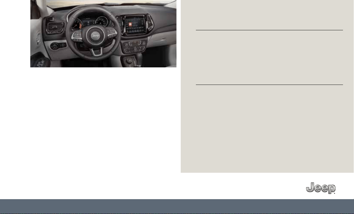
Driving and Alcohol
Drunk driving is one of the most frequent causes of
collisions. Your driving ability can be seriously impaired with
blood alcohol levels far below the legal minimum. If you are
drinking, don’t drive. Ride with a designated non-drinking
driver, call a cab, a friend or use public transportation.
WARNING!
Driving after drinking can lead to a collision.
Your perceptions are less sharp, your reflexes are slower
and your judgment is impaired when you have been
drinking. Never drink and then drive.
Important
Get warranty and other information online – you can review and
print or download a copy of the Owner’s Manual, Navigation/
Uconnect manuals and the limited warranties provided by
FCA US LLC for your vehicle by visiting www.mopar.com (U.S.)
or www.owners.mopar.ca (Canada). Click on the applicable
link in the “Popular Topics” area of the www.mopar.com (U.S.)
or www.owners.mopar.ca (Canada) homepage and follow the
instructions to select the applicable year, make and model of
your vehicle.
If you are the first registered retail owner of your vehicle, you may
obtain a complimentary printed copy of the Warranty Booklet by
calling 1-877-426-5337 (U.S.) or 1-800-387-1143 (Canada) or by
contacting your dealer.
The driver’s primary responsibility is the safe operation of the
vehicle. Driving while distracted can result in loss of vehicle control,
resulting in a collision and personal injury. FCA US LLC strongly
recommends that the driver use extreme caution when using any
device or feature that may take their attention o the road.
Use of any electrical devices, such as cellular telephones, computers,
portable radios, vehicle navigation or other devices, by the driver
while the vehicle is moving is dangerous and could lead to a serious
collision. Texting while driving is also dangerous and should never be
done while the vehicle is moving.
If you find yourself unable to devote your full attention to vehicle
operation, pull o the road to a safe location and stop your vehicle.
Some states or provinces prohibit the use of cellular telephones or
texting while driving. It is always the driver’s responsibility to comply
with all local laws.
This guide has been prepared to help you get quickly
acquainted with your new Jeep
brand vehicle and to
provide a convenient reference for common
questions. However, it is not a substitute for your
Owner’s Manual.
For complete operational instructions, maintenance
procedures and important safety messages, please
consult your Owner’s Manual, Navigation/Uconnect
manuals found on the website on the back cover
and other Warning Labels in your vehicle.
Not all features shown in this guide may apply
to your vehicle. For additional information on
accessories to help personalize your vehicle, visit
www.mopar.com (U.S.), www.mopar.ca (Canada)
or your local Jeep
brand dealer.
WARNING: Operating, servicing and maintaining a passenger vehicle or off-road
highway motor can expose you to chemicals including engine exhaust, carbon monoxide,
phthalates, and lead, which are known to the State of California to cause cancer and
birth defects or other reproductive harm. To minimize exposure, avoid breathing exhaust,
do not idle the engine except as necessary, service your vehicle in a well-ventilated area
and wear gloves or wash your hands frequently when servicing your vehicle. For more
information go to:
www.p65Warnings.ca.gov/passenger-vehicle

©2018 FCA US LLC. All Rights Reserved. Jeep is a registered trademark of FCA US LLC.
App Store is a registered trademark of Apple Inc. Google Play Store is a registered trademark of Google.
Whether it’s providing information about specific product features, taking a tour through your
vehicle’s heritage, knowing what steps to take following an accident or scheduling your next
appointment, we know you’ll find the app an important extension of your Jeep
brand vehicle.
Simply download the app, select your make and model and enjoy the ride.
To get this app, go directly to the App Store® or Google Play® Store and enter the search keyword “JEEP”
(U.S. residents only).
www.jeep.com⁄en ⁄owners (U.S.) provides special oers tailored to your needs, customized vehicle galleries,
personalized service records and more. To get this information, just create an account and check back often.
Get warranty and other information online – you can review and print or download a copy of the Owner’s
Manual, Navigation ⁄ Uconnect manuals and the limited warranties provided by FCA US LLC for your vehicle
by visiting www.mopar.com (U.S.) or www.owners.mopar.ca (Canada). Click on the applicable link in the
“Popular Topics” area of the mopar.com (U.S.) or www.owners.mopar.ca (Canada) homepage and follow
the instructions to select the applicable year, make and model of your vehicle.
DOWNLOAD A FREE ELECTRONIC COPY of the most up-to-date Owner’s Manual,
media and warranty booklet by visiting:
www.mopar.com/en-us/care/owners-manual.html (U.S. residents);
www.owners.mopar.ca (Canadian residents).
Jeep.com (U.S.)
Jeep.ca (Canada)
19WK-926-AA
Second Edition
2019 GRAND CHEROKEE USER GUIDE