Loading ...
Loading ...
Loading ...
Version 7/11 - Page 6
6. Reattach the control box and support. Make sure that
the wiring harness is concealed behind the support.
7. Remove the eld wiring compartment cover. Feed the
Power Supply Cable through the electrical knockout.
8. Attach the backdraft damper to the proper exhaust open-
ing using two silver screws supplied with the rangehood.
Attach the rangehood to the cabinet bottom. The four
key holes slip onto the four screws mounted to the cabinet
bottom. Tighten the screws.
Connect the Power Supply Cable to the rangehood.
Attach the White lead of the power supply to the White lead
of the rangehood with a twist-on type wire connector. Attach
the Black lead of the power supply to the Black lead of the
rangehood with a twist-on type wire connector. Connect
the Green (Green and Yellow) ground wire under the Green
grounding screw.
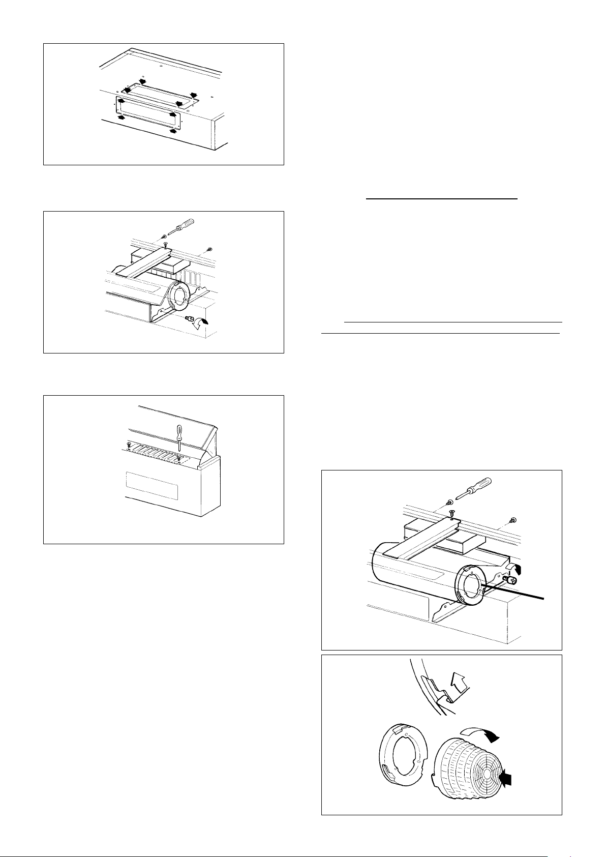
4. Remove the central support and control box by remov-
ing the screws indicated in FIGURE 11. It is not necessary
to remove the blower to perform this operation.
5. Attach the cover behind the exhaust grate with two silver
screws supplied with the rangehood as indicated in FIGURE 12.
11. Replace the eld wiring compartment cover. For duct-
less installations, refer to the next section which discusses
ductless installations. Replace the grease lters.
12. Turn the power supply on. Turn on blower and light.
IF THE RANGEHOOD DOES NOT OPERATE:
• Check that the circuit breaker is not tripped or the
house fuse blown.
• Disconnect the power supply and check that the
wiring connections have been made properly.
DUCTLESS INSTALLATIONS
For ductless installations, the blower must be positioned with
the exhaust pointing forward ( so that the exhaust exits from
the front grill ) before attaching the rangehood to the cabinet.
Ductless installations require Charcoal Filters.
1. Remove both grease lters, the central support and the
control box. Remove the two thumb screws on either side of
the blower and remove the blower from the mounting guides
as indicated in FIGURE 11.
2.
.
Then Rotate the blower 180° so that the exhaust points out
the front of the rangehood. Replace the black lter holders
and the two thumb screws and tighten so that the blower
is securely fastened inside the rangehood as indicated in
. Reattach the control box and central support.
Make sure that the wiring harness is concealed behind the
central support.
For ductless installations, Charcoal Filters are required
and must be installed before the grease lters are replaced.
The charcoal lters attach to both ends of the blower as
indicated in FIGURE 14.
FIGURE 11
FIGURE 12
FIGURE 14
A
A
Loading ...
Loading ...
Loading ...