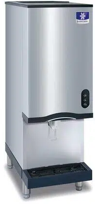
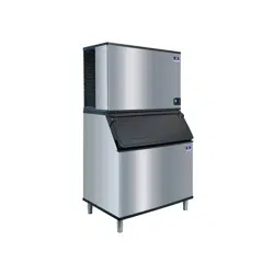
User manual Icemaker
Installation
-476446.png)
PERSONAL INJURY POTENTIAL
Remove all ice machine panels before lifting and installing.
Location of Ice Machine
- The location selected for the ice machine must meet the following criteria. If any of these criteria are not met, select another location.
- The location must be indoors and free of airborne and other contaminants..
- The air temperature must be at least 45°F (7°C), but must not exceed 110°F (43°C).
- The water temperature must be at least 45°F (7°C), but must not exceed 90°F (32°C).
- The location must not be near heat-generating equipment or in direct sunlight.
- The location must be capable of supporting the weight of the ice machine and a full bin of ice and allow the ice machine to be level front to back and side to side.
- The location must allow enough clearance for water and electrical connections in the rear of the ice machine. The drain can be routed out the rear or bottom of dispenser.
- The location must not obstruct airflow through or around the ice machine. Airflow is in the left side and out the top. Refer to chart for clearance requirements.
- The ice machine must be protected if it will be subjected to temperatures below 32°F (0°C). Failure caused by exposure to freezing temperatures is not covered by the warranty. See “Removal from Service/ Winterization”
Ice Machine Clearance Requirements
-535830.png)
Ice Machine Heat of Rejection
-956807.png)
Ice machines, like other refrigeration equipment, reject heat through the condenser. It is helpful to know the amount of heat rejected by the ice machine when sizing air conditioning equipment where self-contained air-cooled ice machines are installed.
Electrical Service
General
All wiring must conform to local, state and national codes.
Voltage
The maximum allowable voltage variation is ± 10% of the rated voltage on the ice machine model/serial number plate at start-up (when the electrical load is highest).
Fuse/Circuit Breaker
A separate fuse/circuit breaker must be provided for each ice machine. Circuit breakers must be H.A.C.R. rated (does not apply in Canada).
The ice machine must be grounded in accordance with national and local electrical codes.
CIRCUIT AMPACITY
The minimum circuit ampacity is used to help select the wire size of the electrical supply. (Minimum circuit ampacity is not the ice machine’s running amp load.)
The wire size (or gauge) is also dependent upon location, materials used, length of run, etc., so it must be determined by a qualified electrician.
-217951.png)
Ice Machine Head Section Water Supply and Drains
POTABLE WATER SUPPLY
The ice machine must be connected to a potable water supply only. Local water conditions may require treatment of the water to inhibit scale formation, filter sediment, remove chlorine, and improve taste and clarity.
Important
If you are installing a Manitowoc water filter system, refer to the Installation Instructions supplied with the filter system for ice making water inlet connections.
POTABLE WATER INLET LINES
Follow these guidelines to install water inlet lines:
- Do not connect the ice machine to a hot water supply.
- Be sure all hot water restrictors installed for other equipment are working. (Check valves on sink faucets, dishwashers, etc.)
- If water pressure exceeds the maximum recommended pressure of 80 psig (5.5 Bar), obtain a water pressure regulator from your Manitowoc Distributor.
- Install a water shut-off valve and union for both the ice making and condenser water lines.
- Insulate water inlet lines to prevent condensation.
DRAIN CONNECTIONS
Follow these guidelines when installing drain lines to prevent drain water from flowing back into the ice machine and storage bin:
- Drain lines must have a 1.5 in. drop per 5 ft. of run (2.5 cm per meter), and must not create traps.
- The floor drain must be large enough to accommodate drainage from all drains.
- Run separate bin drain line. Insulate to prevent condensation.
- Vent the bin drain to the atmosphere.
- Drains must have a union or other suitable means to allow a place of disconnection from the ice machine when servicing is required.
Operation
Ice Making Sequence of Operation
CNF201 - CNF202 NUGGET MACHINES
Ice Making Sequence of Operation
PRIOR TO START-UP
When the toggle switch is placed in the ICE position, the following must occur in the listed order before ice making will start.
- The 15-minute delay period must be expired. The delay period starts upon application of power or a change in toggle switch position.
- The ice chute damper must be in the closed or down position.
- The water sensing switch must be closed (water reservoir full of water and water sensing float in the up position).
INITIAL START-UP
A 15-minute delay period must expire. The delay period starts to time out upon application of power and can only be overridden by depressing the test switch on the control board. The gear motor energizes and when water in the reservoir closes the water sensing (float switch) the compressor and condenser fan motor energize.
FREEZE CYCLE
The float valve automatically maintains the water level in the reservoir. The ice damper will open and close to verify ice production. The ice machine will continue to make ice until the ice damper is held open (up) as ice fills the bin.
AUTOMATIC SHUTOFF
When the ice damper is held open by ice, the gear motor, compressor and condenser fan de-energize. The ice machine will remain off until the 15-minute delay period expires and the ice damper closes.
RESTART AFTER AUTOMATIC SHUTOFF
The 15-minute delay period must be expired. The delay period starts when the ice machine enters Automatic Shutoff and can not be overridden.
The restart sequence is dependent on the amount of time the ice machine has been off:
1. The ice machine was off for less than 30 minutes.
When the 15-minute delay period expires, the gear motor, compressor and condenser fan motor energize.
2. The ice machine was off for more than 30 minutes.
The gear motor and dump valve energize to drain the water from the evaporator and reservoir. After 45 seconds, the dump valve de-energizes. When the reservoir fills with water, the water sensing switch closes and the compressor and condenser fan motor energize.
CHANGING TOGGLE SWITCH POSITION IN THE FREEZE CYCLE
Moving the toggle switch from ICE to OFF will start a 15-minute delay period.
- Moving the toggle switch immediately to the ICE position - The ice machine waits 15 minutes, then starts.
- Moving the toggle switch to the ICE position after 15 minutes have elapsed - The ice machine immediately starts.
Control Board Features
POWER INTERRUPTION DELAY
If power is disconnected, the ice machine stops. When power is reapplied, a 15-minute delay is initiated.
SAFEGUARDS
The ice machine control board has safety features to protect the ice machine from severe failures. The ice machine will stop when conditions arise that would cause major component failure. Refer to Safeguards for details.
TOUCH PAD SEQUENCE OF OPERATION
- The control board monitors the touch pad. Pressing/ selecting Ice, Water, or Ice & Water will energize the corresponding blue Led selection and waits for dispense lever or touchless sensor activation.
- Depressing the dispense lever or activating the touchless sensor closes the relay selected with the touch pad. Depending on selection, either the water solenoid, ice dispense motor or both components activate.
WATER LEVEL CHECK
The float valve maintains the correct water level. The water level is factory set and normally will not require adjustment. The water level is correct if the Water Level indicator light is energized and no water is entering the overflow tube.
The float valve is secured with 2 stop nuts. If an adjustment is required, raise or lower the stop nuts as needed.
Maintenance
Maintenance procedures or failures due to a lack of maintenance are not covered by the warranty.
Manitowoc Ice Machine Cleaner and Sanitizer are the only products approved for use in Manitowoc ice machines.
Caution
Use the correct Manitowoc approved metal safe Ice Machine Cleaner (part number 000000084) and Sanitizer (part number 9405653). It is a violation of Federal law to use these solutions in a manner inconsistent with their labeling. Read and understand all labels printed on bottles before use.
Caution
Do not mix Cleaner and Sanitizer solutions together. It is a violation of Federal law to use these solutions in a manner inconsistent with their labeling.
Wear rubber gloves and safety goggles (and/or face shield) when handling ice machine Cleaner or Sanitizer.
If you do not understand the procedures or the safety precautions that must be followed, call your local Manitowoc Distributor or Manitowoc Ice.
Manitowoc’s Cleaning Technology
Manitowoc CNF201 - CNF202 Ice Machines allow the initiation and completion of a cleaning cycle at the flip of a switch. This cycle will permit cleaning of all surfaces that come in contact with the water distribution system. Periodic maintenance must be performed that includes sanitizing the bin and adjacent surface areas, which are not contacted by the water distribution system.
Depending on local water conditions Manitowoc recommends initiating preventative maintenance cleaning procedures between the 6-month cleanings. This preventive maintenance removes mineral build-up from the evaporator, which results in peak efficiency and lower operating costs.
This technology allows initiation and completion of a clean cycle, after which the ice machine automatically starts ice making again.
There are three separate cleaning procedures.
Heavily Scaled Cleaning Procedure
Perform this procedure if you have some or all of these symptoms.
- Grinding, popping or squealing noises from the evaporator.
- Grinding noise from gearbox.
- Ice machine trips speed sensor.
- A Cleaning/Sanitizing Procedure must be performed after this procedure.
Cleaning/Sanitizing Procedure
This procedure must be performed a minimum of once every six months:
- All ice must be removed from the bin/dispenser.
- The ice machine and bin/dispenser must be disassembled, cleaned and sanitized.
- The ice machine produces ice with the cleaner and sanitizer solutions.
- All ice produced during the cleaning and sanitizing procedure must be discarded.
Preventative Maintenance Cleaning Procedure
Perform this procedure as often as required for your water conditions:
- Allows cleaning the ice machine without removing all of the ice from the bin/dispenser.
- Removes mineral deposits from areas that are in direct contact with water during the Freeze cycle (reservoir, evaporator, auger, drain lines).
EXTERIOR CLEANING
Clean the area around the ice machine as often as necessary to maintain cleanliness and efficient operation. Use cleaners designed for use with stainless steel products.
Sponge any dust and dirt off the outside of the ice machine with mild soap and water. Wipe dry with a clean, soft cloth.
Heavy stains should be removed with stainless steel wool. Never use plain steel wool or abrasive pads. They will scratch the panels.
WEEKLY
Remove grill from scrap ice tray and wipe splash panel, scrap ice tray and grill with sanitizer & water solution. Pour excess solution in scrap ice tray to clear drain.
TOUCHLESS SENSOR ONLY
Wipe sensor window with a soft cloth and mild detergent. Rinse with clear water and dry with a clean soft cloth.
Dust and dirt can be removed from exterior surfaces with mild household dish-washing detergent and warm water. Wipe dry with a clean, soft cloth.
Preventative Maintenance Procedure
Ice machine cleaner is used to remove lime scale or other mineral deposits. It is not used to remove algae or slime. Refer to “Sanitizing Procedure” for removal of algae and slime. To initiate a cleaning cycle using Manitowoc’s Cleaning Technology use the following procedure.
Step 1 To start a cleaning cycle, move the toggle switch to the CLEAN position. Water will flow through the water dump valve and down the drain.
Step 2 Remove the top panel and translucent plastic ice chute cover. Wait about one minute then add the proper amount of Manitowoc Ice Machine Cleaner. Rinse the cleaner from the top of the evaporator with 2 ounces (60 ml) of clear water and re-install cover
Caution
Use only Manitowoc approved Ice Machine Cleaner part number 000000084. It is a violation of Federal law to use these solutions in a manner inconsistent with their labeling. Read and understand all labels printed on bottles before use.
-878777.png)
Step 3 The ice machine will run a wash cycle, a series of rinse cycles and then stop. This entire cycle lasts approximately 30 minutes.
NOTE: Periodic cleaning must be performed on adjacent surface areas not contacted by the water distribution system.
NOTE: The ice machine may be set to start and finish a cleaning procedure, and then automatically start ice making again
A. After cleaner is added, move the switch from CLEAN to ICE position.
B. When the cleaning cycle is complete, ice making will start automatically.
Changing toggle switch position during clean cycle:
- Less than 60 seconds into Clean cycle - The Clean cycle will end when the toggle switch is moved to the OFF position.
- More than 60 seconds into Clean cycle - The ice machine will complete the clean cycle. Toggle switch position will determine the next cycle after the Clean cycle is completed.
- CLEAN POSITION - The ice machine will wait for a change in toggle switch position.
- OFF POSITION - The ice machine will wait for a change in toggle switch position.
- ICE POSITION - The ice machine will start making ice automatically.
- To abort the clean cycle move the toggle switch from CLEAN to OFF to CLEAN and back to OFF within a 15 second time period.
Manitowoc recommends disassembling, cleaning and sanitizing the ice machine and dispenser every six months.
Heavily Scaled Cleaning Procedure
Ice machines that are heavily scaled or have not been cleaned on a regular basis will need to run this Procedure. Failure to do so may result in binding of the auger as the lime scale releases from the auger and evaporator barrel.
Step 1 Remove panels and set the ICE/OFF/CLEAN toggle switch to the OFF position.
Step 2 Remove all ice from the bin.
Step 3 Turn off the water supply to the ice machine.
Step 4 Place ICE/OFF/CLEAN toggle switch in the CLEAN position. The dump valve will open and drain the water from the evaporator and reservoir.
Step 5 Wait approximately 30 seconds (or until the evaporator is drained) and place the toggle switch in the OFF position.
Step 6 Refer to chart and add the correct amount of cleaner for your model ice machine.
CNF201 CNF202 -- 12 ounces (355 ml)
-390548.png)
Step 7 Turn on the water supply to the ice machine.
Importan
Leave the cleaner/water solution in the evaporator for a minimum of 4 hours.
Step 8 Move the toggle switch to the ICE position. The compressor will energize and produce ice with the cleaning solution. Continue the freeze cycle for 15 minutes.
Step 9 Move the toggle switch to the OFF position, then follow the standard cleaning and sanitizing procedures.
Cleaning Procedure
Ice machines that are heavily scaled or have not been cleaned on a regular basis will need to run the Heavily Scaled Cleaning Procedure before this one. Failure to do so may result in binding of the auger as the lime scale releases from the auger and evaporator barrel.
Ice machine cleaner is used to remove lime scale or other mineral deposits. Ice machine sanitizer is used to remove algae or slime.
Step 1 Remove panels and set the ICE/OFF/CLEAN toggle switch to the OFF position.
Step 2 Turn off the water supply to the ice machine.
Step 3 Remove all ice from the bin.
Step 4 Place ICE/OFF/CLEAN toggle switch in the CLEAN position. The dump valve will open and drain the water from the evaporator and reservoir.
Step 5 Wait approximately 30 seconds (or until the evaporator is drained) and place the toggle switch in the OFF position.
Caution
Use only Manitowoc approved Ice Machine Cleaner part number 000000084. It is a violation of Federal law to use these solutions in a manner inconsistent with their labeling. Read and understand all labels printed on bottles before use.
Step 6 Refer to chart and premix the correct solution of cleaner and cool water for your model ice machine.
CNF201 CNF202 -- 2 oz (60 ml) -- 32 oz (1 liter)
Step 7 Remove the top cover from the ice chute and pour the cleaner/water solution into the evaporator. Add the entire amount of premixed solution (excess solution will exit through the overflow tube in the water reservoir).
Step 8 Replace the ice chute cover and allow the ice machine to stand for 30 minutes.
Step 9 Turn on the water supply to the ice machine.
Step 10 Move the toggle switch to the ICE position. The compressor will energize and produce ice with the cleaning solution.
Step 11 The ice machine will freeze and discharge the cleaning solution into the bin. Allow the cycle to run for 15 minutes.
NOTE: Discard all ice produced during the cleaning process. Cleaning and sanitizing must be performed on adjacent surface areas not contacted by the water distribution system. Refer to “Removal of Parts for Cleaning or Sanitizing” on page 38 - Disassemble, clean and sanitize the ice machine a minimum of once every six months.
Sanitizing Procedure
Ice machine sanitizer is used to remove algae or slime. It is not used to remove lime scale or other mineral deposits. Refer to the “Cleaning Procedure” for removal of lime scale or other mineral deposits.
NOTE: Sanitizing must be performed on adjacent surface areas not contacted by the water distribution system. Always perform Component Disassembly for Cleaning/ Sanitizing procedure and a Cleaning Procedure before sanitizing the ice machine.
Step 1 Turn off the water supply to the ice machine.
Step 2 Place ICE/OFF/CLEAN toggle switch in the CLEAN position. The dump valve will open and drain the water from the evaporator and reservoir.
Step 3 Wait approximately 30 seconds (or until the evaporator is drained) and place the toggle switch in the OFF position.
Step 4 Refer to chart and premix the correct solution of sanitizer and cool water for your model ice machine.
CNF201 CNF202 -- 2 ounces (60 ml) -- 3 gallons (11.4L)
Step 5 Remove the top cover from the ice chute and pour the sanitizer/water solution into the evaporator. Add the entire amount of premixed solution (excess solution will exit through the overflow tube in the water reservoir).
Step 6 Replace the ice chute cover and allow the ice machine to stand for 30 minutes.
Step 7 Turn on the water supply to the ice machine.
Step 8 Move the toggle switch to the ICE position. The compressor will energize after the 15 minute delay and produce ice with the sanitizing solution.
Step 9 The ice machine will freeze and discharge the sanitizing solution into the bin. Allow the cycle to run for 15 minutes.
Step 10 Discard all ice produced during the sanitizing process.
Step 11 Place the toggle switch in the CLEAN position. The ice machine will automatically time out a series of flush and rinse cycles, and then stops. This entire cycle lasts approximately 30 minutes.
Step 12 Refer to Component Disassembly for Cleaning and Sanitizing and remove, clean and sanitize all parts listed.
Component Disassembly for Cleaning and Sanitizing
Disconnect electric power to the ice machine at the electric switch box before proceeding.
Wear rubber gloves and safety goggles (and/or face shield) when handling Ice Machine Cleaner or Sanitizer.
Caution
Do not mix Cleaner and Sanitizer solutions together. It is a violation of Federal law to use these solutions in a manner inconsistent with their labeling.
GENERAL INFORMATION
The ice machine must be disassembled, cleaned and sanitized every six months.
- Turn off the water supply to the ice machine at the water service valve, or disconnect water supply line at float valve quick disconnect by depressing stainless steel lever.
- Remove the components you want to clean or sanitize. See the pages specific to the model you are working on for removal procedures.
- Soak the removed parts to clean and sanitize.
| Solution Type |
Water |
Mixed With |
| Cleaner |
1 gal. (4 L) |
16 oz. (500 ml) cleaner |
| Sanitizer |
6 gal. (23 L) |
4 oz. (120 ml) sanitizer |
4. Use a soft-bristle brush or sponge (NOT a wire brush) to carefully clean the parts.
5. Use the solution and a brush to clean all disassembled components and the inside of the bin.
6. Re-install the removed parts and turn on the water and electrical supply.
Removal of Parts for Cleaning or Sanitizing
1. Turn off water supply to ice machine.
2. Place toggle switch in the clean position for 30 seconds to drain water from reservoir, then move toggle switch to Off position.
3. Run dispenser to transfer all ice from the bin to a container.
Disconnect electric power to the ice machine at the electric switch box before proceeding.
4. Disconnect electrical power to the ice machine.
5. Remove top cover.
A. Remove two screws.
B. Lift up on top cover to remove.
-970218.png)
6. Remove front cover.
A. Lift up on front cover.
B. Pull forward to disengage keyhole slots.
-937685.png)
7. Remove side panels.
8. Remove ice chute cover
A. Turn the two thumbscrews 1/4 turn.
B. Lift to remove cover.
-727919.png)
-440265.png)
9. Lift out ice damper
-4069.png)
10. Lift out ice strainer ramp.
-778583.png)
11. Turn ice wiper counterclockwise to remove.
-971340.png)
12. Loosen ice chute hose clamp.
13. Disconnect ice chute drain.
14. Lift up on ice chute to remove. The ice chute must be removed before the bin cover can be removed.
-48052.png)
15. The ice chute can be cleaned in place. If complete removal is desired, use a Phillips screwdriver to remove the Hall Effect switch assembly from the ice chute.
-862481.png)
16. Remove three thumbscrews, then remove bin cover.
-898527.png)
Importan
Do not pour cleaner or sanitizer solutions into the bin. The solution will leak out of the front of the bin and into the compressor compartment.
17. Remove agitator bar.
• CNF201 - Remove the thumbscrew and lift off.
• CNF202 - Unscrew the upright agitator bar.
NOTE: Bar must be reassembled by inserting front edge into the paddle wheel, then lowering the back edge (rounded 90 angle) to prevent water leakage into the compressor compartment.
-960127.png)
18. Remove ice deflector.
A. Remove the two thumbscrews.
B. Lift the ice deflector out.
-281600.png)
19. Remove ice dispensing wheel by lifting straight out.
-871214.png)
20. Water Reservoir Cover Removal
A. Push up on cover to snap off
-252327.png)
CLEANING THE CONDENSER
Disconnect electric power to the ice machine at the electric service switch before cleaning the condenser. The condenser fins are sharp. Use care when cleaning them.
A dirty condenser restricts airflow, resulting in excessively high operating temperatures. This reduces ice production and shortens component life. Clean the condenser at least every six months. Follow the steps below.
1. The washable foam filter on self-contained ice machines is designed to catch dust, dirt, lint and grease. This helps keep the condenser clean. Clean the filter with a mild soap and water solution.
2. Clean the outside of the condenser with a soft brush or a vacuum with a brush attachment. Clean from top to bottom, not side to side. Be careful not to bend the condenser fins.
3. Shine a flashlight through the condenser to check for dirt between the fins. If dirt remains:
A. Blow compressed air through the condenser fins from the inside. Be careful not to bend the fan blades.
B. Use a commercial condenser coil cleaner. Follow the directions and cautions supplied with the cleaner.
4. Straighten any bent condenser fins with a fin comb.
5. Carefully wipe off the fan blades and motor with a soft cloth. Do not bend the fan blades. If the fan blades are excessively dirty, wash with warm, soapy water and rinse thoroughly.
If you are cleaning the condenser fan blades with water, cover the fan motor to prevent water damage.
Removal from Service/Winterization
GENERAL
Special precautions must be taken if the ice machine is to be removed from service for an extended period of time or exposed to ambient temperatures of 32°F (0°C) or below.
Caution
If water is allowed to remain in the ice machine in freezing temperatures, severe damage to some components could result. Damage of this nature is not covered by the warranty.
- Disconnect the electric power at the circuit breaker or the electric service switch.
- Turn off the water supply.
- Disconnect and drain the incoming ice-making water line at the rear of the ice machine.
- Disconnect drain tubing (from the inlet to dump valve) and drain water into container and discard.
- Make sure water is not trapped in any of the water or drain lines.
Troubleshooting
SafeGuard Feature
The ice machine will stop when conditions arise that would cause major component failure.
Standby Mode
The first time a failure occurs, the ice machine deenergizes and initiates a Standby Mode. The ice machine will remain off for 60 minutes, then automatically restart to see if the problem reoccurs. If the same failure keeps occurring, the ice machine will initiate a SafeGuard Mode and remain off until manually restarted.
SafeGuard Indicator Lights
During a SafeGuard Mode, the corresponding control board light will flash continuously.
The SafeGuard will remain in memory for 48 hours of ice making time. After 48 hours of ice making time, the SafeGuard will automatically be erased. If power is interrupted during the 48 hours, the timing will resume when power is applied to the ice machine.
Placing the toggle switch in the OFF position:
The corresponding light will flash continuously.
Placing the toggle switch in the ICE position:
The light will de-energize and a start-up sequence will initiate. The corresponding light will flash anytime the toggle switch is placed in the OFF position provided 48 hours of ice making time has not been exceeded.
Reset Procedure
1. Move the ICE/OFF/CLEAN toggle switch to OFF.
A. If a safeguard feature has stopped the ice machine, it will restart after a short delay. Proceed to Step 2.
B. If the ice machine does not restart, see “Ice Machine Does Not Operate.”
2. Allow the ice machine to run to determine if the condition is reoccurring.
A. If the ice machine continues to run, the condition has corrected itself. Allow the ice machine to continue running.
B. If the ice machine stops, determine the safeguard mode, then refer to the specific safeguard for troubleshooting procedures.
SafeGuards
- No Water
- No Ice Production
NO WATER
The water sensing switch opens for more than 30 seconds.
Operation
When the float switch is open at initial start-up, the ice machine will wait for the switch to close before starting.
During the freeze cycle, if the water float opens for 30 seconds, the ice machine will:
- De-energize the compressor and gear motor.
- The Water Ok light on the control board will deenergize.
- A 15-minute delay is initiated.
The water Ok light will flash when the float switch closes or when the toggle switch is placed in the OFF position.
The ice machine will remain off until the 15-minute delay period expires and the water float switch closes.
NO ICE PRODUCTION
The ice damper did not open and close at least once every 90 seconds in the freeze cycle.
Operation
During the first 12 minutes of operation:
The control board must see the ice damper open/close at least once. This allows time for ice production to start at all ambient temperatures.
After the initial 12-minute period:
The control board must see the ice damper open/close at least once every 90 seconds.
When the ice damper does not open/close within the specified time, the control board will:
1. De-energize the compressor and gear motor.
2. HES #1 light on the control board will flash (the light will not flash if the ice damper is open).
3. A 15-minute delay is initiated.
4. After the 15-minute delay the ice machine will:
A. Energize the dump valve for 30 seconds
B. Energize the gear motor
C. Wait until the water float valve closes and then energize the compressor and fan motor.
5. If the ice damper fails to open/close at least once in the initial 12-minute period, the control board will initiate another safety shutdown. This sequence will repeat until:
A. The ice machine restarts and operates normally for 10 minutes.
B. The ice machine is unable to run normally within 300 minutes of the initial shutdown.
If the ice machine does not run normally within 300 minutes of the initial shutdown, the control board will lock out and require a manual reset.
The control board will flash the HES #1 light anytime the toggle switch is placed in the OFF position for the first 48 hours after the failure.
Reset Procedure
Move the ICE/OFF/CLEAN toggle switch from OFF to ICE or disconnect and reapply power to the ice machine
Ice Machine Will Not Run Diagnostics
High (line) voltage is applied to the control board (terminals #39 and #90) at all times. Removing control board fuse or moving the toggle switch to OFF will not remove the power supplied to the control board.
The following sequence describes the normal startup procedure for the ice machine when line voltage is disconnected then reconnected to the ice machine.
- Power is supplied to the control board.
- The control board lights race (energize/de-energize in sequence) to indicate the ice machine is in a 15-minute delay mode.
- When the 15-minute delay ends, the ice machine starts. The following lights are energized:
The HES #1 light will de-energize and re-energize as ice passes beneath the ice damper.
When the ice damper lifts approximately 45 degrees, HES #2 de-energizes and the ice machine shuts off immediately on full bin. A 15-minute time delay is initiated, which prevents the ice machine from immediately restarting.
Refrigeration Diagnostics
BEFORE BEGINNING SERVICE
Ice machines may experience operational problems only during certain times of the day or night. A machine may function properly while it is being serviced, but malfunctions later. Information provided by the user can help the technician start in the right direction, and may be a determining factor in the final diagnosis.
Ask these questions before beginning service:
- When does the ice machine malfunction? (night, day, all the time, only during the Freeze cycle, etc.)
- When do you notice low ice production? (one day a week, every day, on weekends, etc.)
- Can you describe exactly what the ice machine seems to be doing?
- Has anyone been working on the ice machine?
- During “store shutdown,” is the circuit breaker, water supply or air temperature altered?
- Is there any reason why incoming water pressure might rise or drop substantially?
ANALYZING DISCHARGE PRESSURE
- Determine the ice machine operating conditions:
- Air temperature entering condenser
- Air temperature around ice machine
- Water temperature entering water reservoir
- Refer to 24-Hour Ice Production/Refrigeration Pressure Chart for ice machine being checked. Use the operating conditions determined in Step 1 to find the published normal discharge pressures and compare to actual discharge pressure readings.
- Measure the actual discharge pressure.
- Compare the actual discharge pressure (step 3) with the published discharge pressure (step 2). The discharge pressure is normal when the actual pressure falls within the published pressure range for the ice machine’s operating conditions.
Discharge Pressure High Checklist
| Problem |
Cause |
| Improper installation |
Refer to “Installation/Visual Inspection Checklist.” |
| Restricted condenser air flow |
Dirty air filter
High inlet air temperature
Condenser discharge air recirculation
Dirty condenser fins
Defective fan motor |
| Improper refrigerant charge |
Overcharged
Non-condensible in system
Wrong type of refrigerant |
| Other |
Non-Manitowoc components in system
High side refrigerant line/component restricted (before mid-condenser)
|
Discharge Pressure Low Checklist
| Problem |
Cause |
| Improper installation |
Refer to “Installation/Visual Inspection Checklist.” |
| Improper refrigerant charge |
Undercharged
Wrong type of refrigerant
|
| Other |
Low ambient temperature
Non-Manitowoc components in system
High side refrigerant lines/component restricted (before mid-condenser)
Suction pressure is too low and affecting discharge pressure. (Refer to “Suction Pressure Low Checklist.”)
No water or insufficient pressure
Expansion valve incorrectly adjusted
Defective compressor
Moisture in refrigeration system |
NOTE: Do not limit your diagnosis to only the items listed in the checklists.
ANALYZING SUCTION PRESSURE
NOTE: Analyze discharge pressure before analyzing suction pressure.
High or low discharge pressure may be causing high or low suction pressure.
Suction Pressure High Checklist
| Problem |
Cause |
| Improper installation |
Refer to “Installation/Visual Inspection Checklist.” |
| Discharge pressure |
Discharge pressure is too high and is affecting suction pressure. Refer to “Discharge Pressure High Checklist.” |
| Improper refrigerant charge |
Overcharged
Wrong type of refrigerant
Non condensible in system
|
| Other |
Dump valve leaking
Non-Manitowoc components in system
Expansion valve incorrectly adjusted
Defective compressor |
Suction Pressure Low Checklist
| Problem |
Cause |
| Improper installation |
Refer to “Installation/Visual Inspection Checklist.” |
| Discharge pressure |
Discharge pressure is too low and is affecting suction pressure. Refer to “Discharge Pressure Low Checklist.” |
| Improper refrigerant charge |
Undercharged
Wrong type of refrigerant
|
| Other |
Non-Manitowoc components in system
Restricted/plugged liquid line drier
Restricted/plugged tubing in suction side of
refrigeration system
Expansion valve starving
No water or insufficient pressure
Moisture in refrigeration system
Dirty Evaporator |
NOTE: Do not limit your diagnosis to only the items listed in the checklist.