Part Number: 000014141 Rev 03 2/18
Indigo NXT Ice Machines
Installation, Operation and Maintenance Manual
,
Caution
Read this instruction before operating this equipment.
Original Document


Safety Notices
Safety Notices
Read these precautions to prevent
personal injury:
• Read this manual thoroughly before
operating, installing or performing
maintenance on the equipment. Failure
to follow instructions in this manual
can cause property damage, injury or
death.
• Routine adjustments and maintenance
procedures outlined in this manual are
not covered by the warranty.
• Proper installation, care and
maintenance are essential for
maximum performance and trouble-
free operation of your equipment. Visit
our website www.manitowocice.com
for manual updates, translations, or
contact information for service agents
in your area.
• This equipment contains high
voltage electricity and refrigerant
charge. Installation and repairs are
to be performed by properly trained
technicians aware of the dangers of
dealing with high voltage electricity
and refrigerant under pressure. The
technician must also be certified
in proper refrigerant handling and
servicing procedures. All lockout and
tag out procedures must be followed
when working on this equipment.
• This equipment is intended for indoor
use only. Do not install or operate this
equipment in outdoor areas.
Definitions
DANGER
Indicates a hazardous situation that, if not
avoided, will result in death or serious
injury. This applies to the most extreme
situations.
n
Warning
Indicates a hazardous situation that, if not
avoided, could result in death or serious
injury.
,
Caution
Indicates a hazardous situation that, if not
avoided, could result in minor or moderate
injury.
Notice
Indicates information considered
important, but not hazard-related (e.g.
messages relating to property damage).
NOTE: Indicates useful, extra information
about the procedure you are performing.

n
Warning
Follow these precautions to prevent personal injury during installation of this
equipment:
• Installation must comply with all
applicable equipment fire and health
codes with the authority having
jurisdiction.
• To avoid instability the installation area
must be capable of supporting the
combined weight of the equipment and
product. Additionally the equipment
must be level side to side and front to
back.
• Ice machines require a deflector when
installed on an ice storage bin. Prior to
using a non-OEM ice storage system
with this ice machine, contact the
bin manufacturer to assure their ice
deflector is compatible.
• Prior to installing a non-OEM ice storage
system with this ice machine, follow the
manufacturers installation procedures
and verify the location and installation
meets the local/national mechanical
codes and stability requirements.
• Remove all removable panels before
lifting and installing and use appropriate
safety equipment during installation
and servicing. Two or more people are
required to lift or move this appliance to
prevent tipping and/or injury.
• Legs or casters must be installed and
the legs/casters must be screwed in
completely. When casters are installed
the mass of this unit will allow it to move
uncontrolled on an inclined surface.
These units must be tethered/secured
to comply with all applicable codes.
Swivel casters must be mounted on the
front and rigid casters must be mounted
on the rear. Lock the front casters after
installation is complete.
• Connect to a potable water supply only.
• Do not damage the refrigeration circuit
when installing, maintaining or servicing
the unit.
• This equipment contains refrigerant
charge. Installation of the line sets must
be performed by a properly trained and
EPA certified refrigeration technician
aware of the dangers of dealing with
refrigerant charged equipment.
• Some 50 Hz models may contain
up to 150 grams of R290 (propane)
refrigerant. R290 (propane) is flammable
in concentrations of air between
approximately 2.1% and 9.5% by volume
(LEL lower explosion limit and UEL upper
explosion limit). An ignition source
at a temperature higher than 470°C
is needed for a combustion to occur.
Refer to nameplate to identify the type
of refrigerant in your equipment. Only
trained and qualified personnel aware of
the dangers are allowed to work on the
equipment.

n
Warning
Follow these electrical requirements
during installation of this equipment.
• All field wiring must conform to all
applicable codes of the authority
having jurisdiction. It is the
responsibility of the end user to
provide the disconnect means to satisfy
local codes. Refer to rating plate for
proper voltage.
• This appliance must be grounded.
• This equipment must be positioned so
that the plug is accessible unless other
means for disconnection from the
power supply (e.g., circuit breaker or
disconnect switch) is provided.
• Check all wiring connections, including
factory terminals, before operation.
Connections can become loose during
shipment and installation.
DANGER
Do not operate equipment that has
been misused, abused, neglected,
damaged, or altered/modified from that
of original manufactured specifications.
This appliance is not intended for use by
persons (including children) with reduced
physical, sensory or mental capabilities,
or lack of experience and knowledge,
unless they have been given supervision
concerning use of the appliance by a
person responsible for their safety. Do
not allow children to play with, clean or
maintain this appliance without proper
supervision.
n
Warning
Follow these precautions to prevent
personal injury while operating or
maintaining this equipment:
• Read this manual thoroughly before
operating, installing or performing
maintenance on the equipment. Failure
to follow instructions in this manual
can cause property damage, injury or
death.
• Crush/Pinch Hazard. Keep hands clear
of moving components. Components
can move without warning unless
power is disconnected and all potential
energy is removed.
• Moisture collecting on the floor will
create a slippery surface. Clean up
any water on the floor immediately to
prevent a slip hazard.
• Objects placed or dropped in the bin
can affect human health and safety.
Locate and remove any objects
immediately.
• Never use sharp objects or tools
to remove ice or frost. Do not use
mechanical devices or other means to
accelerate the defrosting process.
• When using cleaning fluids or
chemicals, rubber gloves and eye
protection (and/or face shield) must be
worn.

DANGER
Follow these precautions to prevent personal injury during use and maintenance of this
equipment:
• It is the responsibility of the equipment
owner to perform a Personal Protective
Equipment Hazard Assessment to ensure
adequate protection during maintenance
procedures.
• Do Not Store Or Use Gasoline Or Other
Flammable Vapors Or Liquids In The
Vicinity Of This Or Any Other Appliance.
Never use flammable oil soaked cloths
or combustible cleaning solutions for
cleaning.
• All covers and access panels must be
in place and properly secured when
operating this equipment.
• Risk of fire/shock. All minimum
clearances must be maintained. Do not
obstruct vents or openings.
• Failure to disconnect power at the main
power supply disconnect could result
in serious injury or death. The power
switch DOES NOT disconnect all incoming
power.
• All utility connections and fixtures must
be maintained in accordance with the
authority having jurisdiction.
• Turn off and lockout all utilities (gas,
electric, water) according to approved
practices during maintenance or
servicing.
• Units with two power cords must be
plugged into individual branch circuits.
During movement, cleaning or repair it is
necessary to unplug both power cords.
• Never use a high-pressure water jet for
cleaning on the interior or exterior of
this unit. Do not use power cleaning
equipment, steel wool, scrapers or wire
brushes on stainless steel or painted
surfaces.
• Two or more people are required to
move this equipment to prevent tipping.
• Locking the front casters after
moving is the owner’s and operator’s
responsibility. When casters are installed,
the mass of this unit will allow it to move
uncontrolled on an inclined surface.
These units must be tethered/secured to
comply with all applicable codes.
• The on-site supervisor is responsible for
ensuring that operators are made aware
of the inherent dangers of operating this
equipment.
• Do not operate any appliance with a
damaged cord or plug. All repairs must
be performed by a qualified service
company.

Table of Contents
Part Number: 000014141 Rev 03 2/18 7
Safety Notices
Safety Notices ...........................................................................3
Section 1
General Information
Model Numbers ........................................................................9
Accessories ................................................................................9
How To Read A Model Number ................................................10
Section 2
Installation
Installation ..............................................................................11
Location Requirements ............................................................ 11
Installation Requirements ........................................................11
Ice Machine Heat of Rejection .................................................12
Air Baffle .................................................................................14
Bin Installation Requirements ..................................................14
Bin Installation ........................................................................15
Dispenser Installation .............................................................. 15
Electrical Requirements ........................................................... 16
Maximum Breaker Size & Minimum Circuit Amperage Chart ....17
Water Supply and Drain Line Sizing/Connections ..................... 20
Cooling Tower Applications
(Water-Cooled Models) ...........................................................21
Drain Connections ...................................................................21
Remote Condenser and Condensing Unit Refrigeration System
Installation ..............................................................................22
Calculating Installation Distances ......................................... 23
Remote Condenser Models .................................................. 24
QuietQube Models ............................................................... 25
Starting the Ice Machine ..........................................................29
Remove Ice Thickness Probe Shipping Brackets. .................. 29
Minimum/Maximum Slab Weight ........................................ 29
Remote Ice Machine Usage with Non-Manitowoc Multi-Circuit
Condensers ..............................................................................29

8 Part Number: 000014141 Rev 03 2/18
Table of Contents (continued)
Section 3
Operation
Touch Screen Features .............................................................31
Home Screen Icon Descriptions ............................................ 32
Setup Wizard ........................................................................... 33
Menu Screen Navigation ..........................................................34
Ice Making Sequence of Operation ..........................................35
Control Board Timers ...............................................................35
Minimum/Maximum Slab Weight ............................................37
Ice Thickness Check .................................................................37
Section 4
Maintenance
Cleaning and Sanitizing ............................................................39
Cleaning/Sanitizing Procedure .................................................40
Cleaning Procedure ............................................................... 40
Sanitizing Procedure ............................................................. 42
Parts Removal for Cleaning/Sanitizing .....................................43
Preventative Maintenance Cleaning Procedure ........................44
Cleaning the Air Filter and Condenser ...................................... 45
Removal from Service/Winterization .......................................45
Section 5
Troubleshooting
Before Calling for Service Checklist ..........................................47
Service Faults ..........................................................................49
Part Number: 000014141 Rev 03 2/18 9
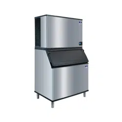
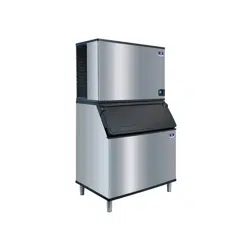
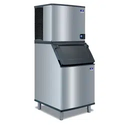
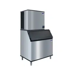
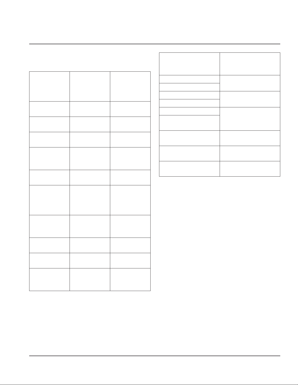
Model Numbers
This manual covers the following models:
Self-
Contained
Air-Cooled
Self-
Contained
Water-
Cooled
Remote Air-
Cooled
IDF0300A
IYF0300A
IDF0300W
IYF0300W
----
----
IDT0420A
IYT0420A
IDT0420W
IYT0420W
----
----
IDT0450A
IYT0450A
IDT0450W
IYT0450W
----
----
IDT0500A
IYT0500A
IRT0500A
IDT0500W
IYT0500W
IRT0500W
IDT0500N
IYT0500N
----
IDF0600A
IYF0600A
IDF0600W
IYF0600W
IDF0600N
IYF0600N
IDT0620A
IYT0620A
IRT0620A
IDP0620A
IDT0620W
IYT0620W
----
----
----
----
----
----
IDF0900A
IYF0900A
IRF0900A
IDF0900W
IYF0900W
----
IDF0900N
IYF0900N
----
IDT1200A
IYT1200A
IDT1200W
IYT1200W
IDT1200N
IYT1200N
IDT1500A
IYT1500A
IDT1500W
IYT1500W
IDT1500N
IYT1500N
IDT1900A
IYT1900A
IRT1900A
IDT1900W
IYT1900W
----
IDT1900N
IYT1900N
IRT1900N
QuietQube
Indoor Head Section
QuietQube
Air-Cooled
Condensing Unit
IYF0600C
CVDF0600
IBF0620C
IBF0820C
CVDF0900
IYF0900C
IBT1020C
CVDT1200
IDT1200C
IYT1200C
IDF1400C
IYF1400C
CVDF1400
IDF1800C
IYF1800C
CVDF1800
IDF2100C
IYF2100C
CVDF2100
Accessories
Ice Deflector
An ice deflector is required when the
ice machine is installed on a bin. An ice
deflector is not required when the ice
machine is installed on a dispenser.
Bin Ice Level Accessory Kit
The bin level accessory connects to
the circuit board and allows bin level
adjustment of Indigo ice machines on B
model bins. Installation instructions are
included with the accessory. A bin level
sensor is required to set a lower level of ice
in the bin.
Section 1
General Information

10 Part Number: 000014141 Rev 03 2/18
General Information Section 1
Top Air Discharge Kit
The top air discharge kit can be used on
select ice machine models. This kit directs
warm exhaust air upward rather than out
the side panels.
AuCS® Automatic Cleaning System
This accessory reduces equipment cleaning
expense. The AuCS® accessory monitors
ice making cycles and initiates cleaning
procedures automatically.
LuminIce® II
The LuminIce® growth inhibitor recirculates
the air in the ice machine foodzone over
a UV bulb. This process will inhibit the
growth of common micro-organisms on all
exposed foodzone surfaces.
How To Read A Model Number
I Y T 1500 N — 261 X
Ice Machine Model
I - Indigo Model
IB - Ice Beverage
X - Luminice
HP - High Pressure Water
Regulating Valve
Ice Cube Size
R - Regular
D - Dice
Y - Half-Dice
Not Used On IB Models
P - Correctional Model
M - Marine Model
V - Space Saver
Q - Coated Condenser
Blank - General Usage
Refrigerant
P - R290
F - R404A
T - R410
Voltage
161 - 115/60/1
261 - 208-230/60/1
251 - 230/50/1
263 - 208-230/60/3
463 - 460/60/3
Nominal Production
Condenser Type
A - Self-Contained Air-Cooled
W - Self-Contained Water-Cooled
N - Remote Air-Cooled
C - CVD Air-Cooled
NOTE: These products are hermetically sealed and contain fluorinated greenhouse gas
R404A or R410A.

Part Number: 000014141 Rev 03 2/18 11
Installation
Location Requirements
The location selected for the ice machine
head section must meet the following
criteria. If any of these criteria are not met,
select another location.
• The location must be indoors and
must be free of airborne and other
contaminants.
• The location must not be near heat-
generating equipment or in direct
sunlight.
• The location must allow enough
clearance for water, drain, and electrical
connections in the rear of the ice
machine.
• The location must not obstruct airflow
through or around the ice machine.
Installation Requirements
• The ice machine and bin must be level.
• Vent the ice machine and bin drains
separately.
• Bin drain termination must have an air
gap.
• The ice machine and bin must be
sanitized after installation.
• The drain line must contain a union or
other suitable means of disconnection at
the ice machine.
QuietQube Models Only
• The ice machine top panel can be
trimmed with an aviator snips to allow
the line set, water line and electrical
connections to exit the top. Only cut out
what is needed, the back panel must
support the top panel.
• The water inlet and electrical connection
must contain a service loop to allow
future access.
Section 2
Installation
12 Part Number: 000014141 Rev 03 2/18
Installation Section 2
Minimum/Maximum Temperatures
Model
Minimum Air
Temperature
Maximum Air
Temperature
All Ice
Machine
Head
Sections
35°F
2°C
110°F
43°C
All Remote
Condensers
-20°F
-29°C
120°F
49°C
QuietQube
Condensing
Units
CVDF0600
CVDF0900
CVDT1200
CVDF2100
-20°F
-29°C
120°F
49°C
CVDF1400
CVDF1800
-20°F
-29°C
130°F
54°C
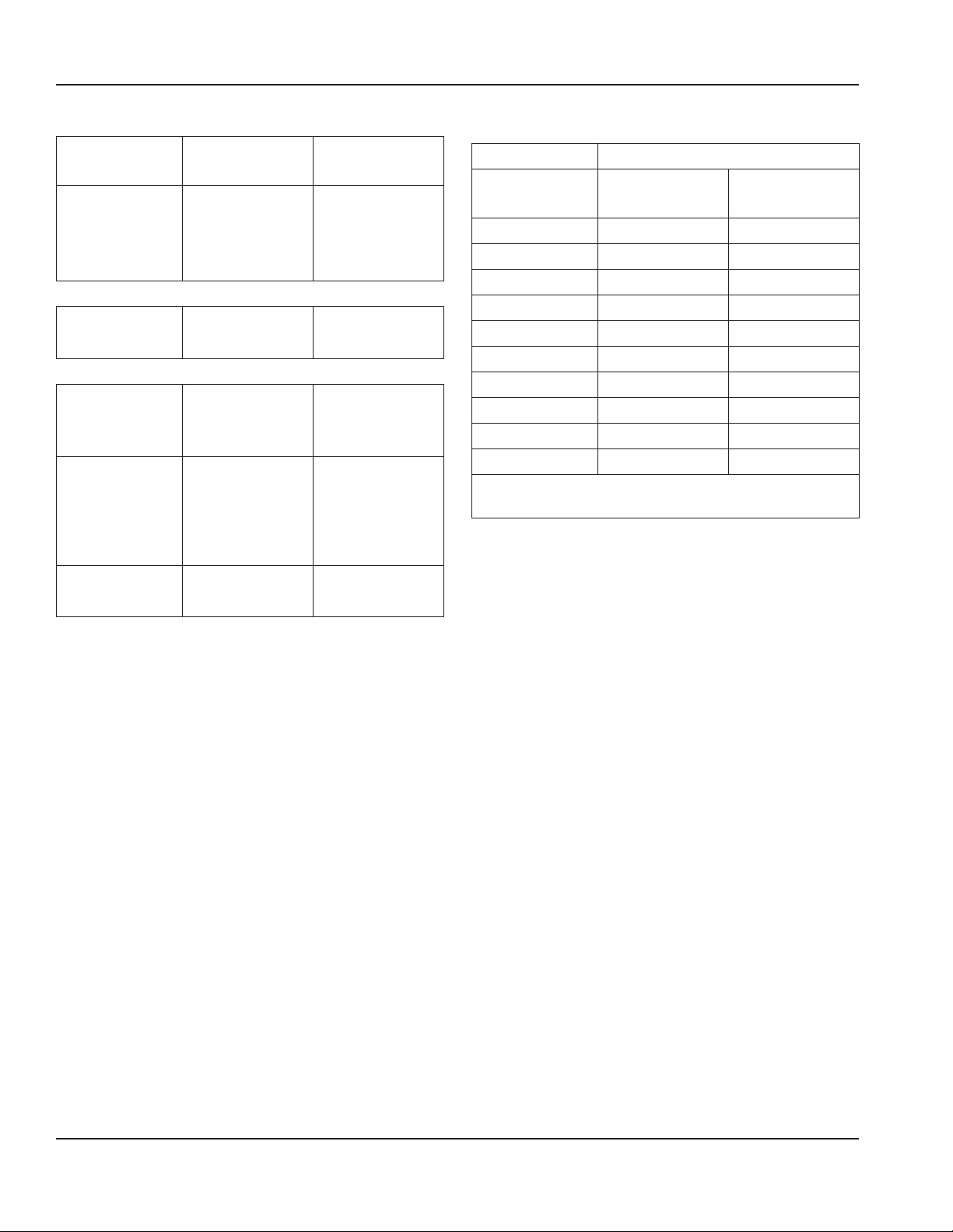
Ice Machine Heat of Rejection
Ice Machine Heat of Rejection
Series
Air
Conditioning
Peak
IF0300 4600 5450
IT0420 *3800 *6000
IT0450 *5400 *6300
IT0500 *6100 *6900
IF0600 9000 13900
IT0620 *9000 *13900
IF0900 13000 16000
IT1200 *20700 *24500
IT1500 23000 27000
IT1900 26100 30500
* Data marked with an asterisk is preliminary
and subject to change.
Use this information when:
• Sizing air conditioning equipment where
self-contained air-cooled ice machines
are installed.
• Determining the load on a cooling tower.
Use the peak figure for sizing the load.
Part Number: 000014141 Rev 03 2/18 13
Section 2 Installation
Clearance Requirements
I0300
Self-
Contained
Air-Cooled
Self-
Contained
Water-Cooled
Top/Sides *16" (40 cm) *8" (20 cm)
Back *5" (13 cm) *5" (13 cm)
IT0420 IT0450
IT0500 IT0620
Self-
Contained
Air-Cooled
Water-Cooled
or Remote
Condenser
Top/Sides 12" (31 cm) 8" (20 cm)
Back 5" (13 cm) 5" (13 cm)
IF0900
Self-
Contained
Air-Cooled
Self-
Contained
Water-Cooled
Top/Sides *8" (20 cm) *8" (20 cm)
Back *5" (13 cm) *5" (13 cm)
* Data marked with an asterisk is preliminary
and subject to change - Model/serial plate
information overrides all data listed in this chart.
IT1200
Self-
Contained
Air-Cooled
Water-Cooled
or Remote
Condenser
Top *8" (20 cm) *8" (20 cm)
Sides *12" (31 cm) *8" (20 cm)
Back *5" (13 cm) *5" (13 cm)
* Data marked with an asterisk is preliminary
and subject to change - Model/serial plate
information overrides all data listed in this chart.
IT1500
Self-
Contained
Air-Cooled
Water-Cooled
or Remote
Condenser
Top 12" (31 cm) 8" (20 cm)
Sides 8" (20 cm) 8" (20 cm)
Back 12" (31 cm) 5" (13 cm)
IT1900
Self-
Contained
Air-Cooled
Water-Cooled
or Remote
Condenser
Top/Sides 24" (61 cm) 8" (20 cm)
Back 12" (31 cm) 5" (13 cm)
NOTE: Top air discharge kits require the
same clearance requirements as the
comparable self-contained air-cooled
model.
QuietQube Model Clearance Requirements
Model Top Back Sides
IF0600C
IF0900C
IT1200C
IF1400C
IF1800C
IF2100C
5"
(13 cm)
5"
(13 cm)
5"
(13 cm)
IBF0620C
IBF0820C
IBF1020C
2"**
(5 cm)
5"
(13 cm)
8" **
(20 cm)
** 61 cm (24") is recommended on top/sides for
servicing
14 Part Number: 000014141 Rev 03 2/18
Installation Section 2
Condensing Unit Clearance Requirements
Model
Top/
Sides
Back Front
CVDF0600
CVDF0900
CVDT1200
CVDF1400
CVDF1800
CVDF2100
0"
(0 cm*)
48"
(122 cm)
48"
(122 cm)
* 61 cm (24") is recommended on top/sides for
servicing
Notice
The ice machine must be protected if it
will be subjected to temperatures below
32°F (0°C). Failure caused by exposure to
freezing temperatures is not covered by
the warranty.
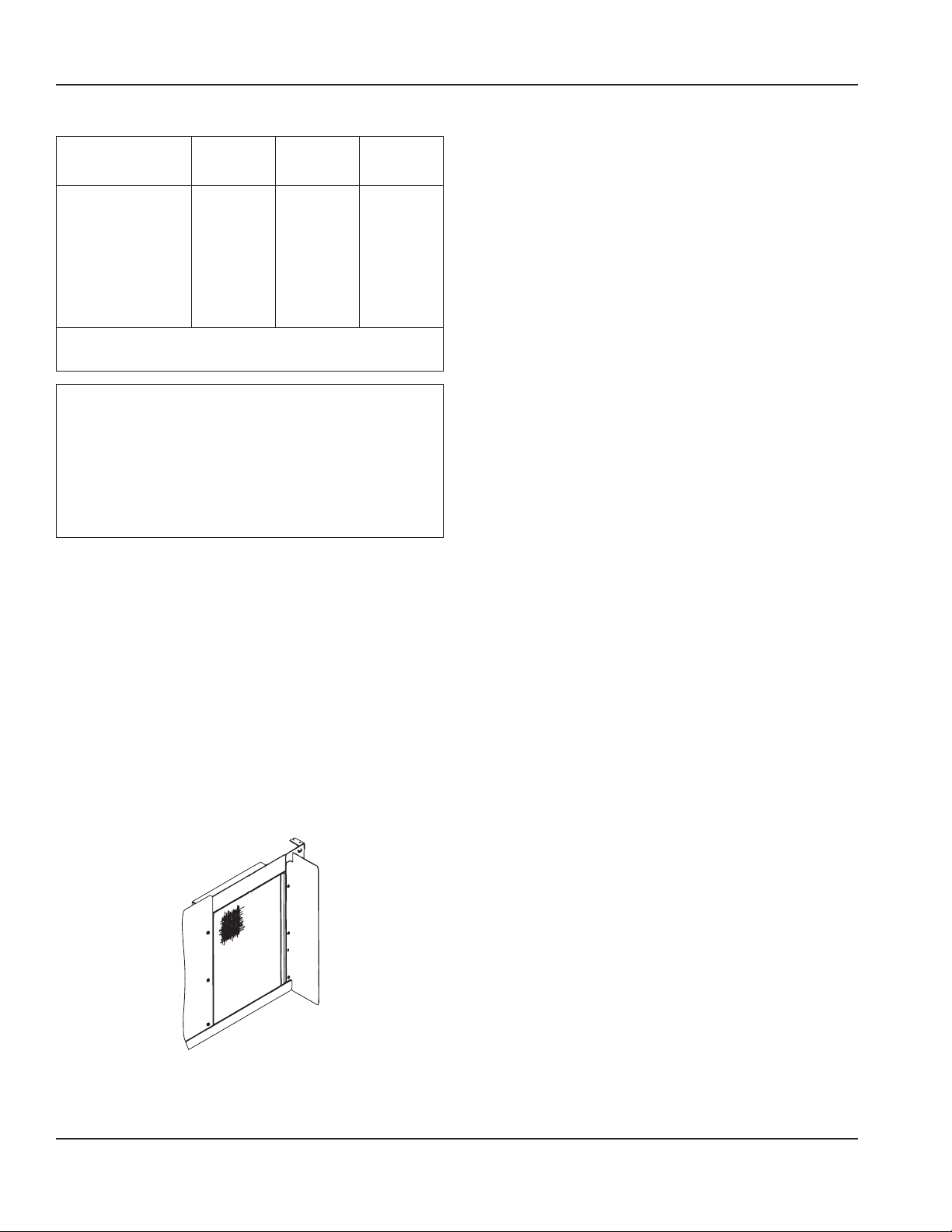
Air Baffle
Self-Contained Air-cooled Only
The air-cooled baffle prevents condenser
air from recirculating. To install:
1. Loosen the back panel screws next to
the condenser.
2. Align the keyhole slots in the air baffle
with the screw holes and slide the
baffle down to lock in place.
Bin Installation Requirements
• The installation area must be capable of
supporting the combined weight of the
equipment and product.
• All ice machines installed on a bin
require an ice deflector.
• Manitowoc bins have a deflector
installed and require no modifications
when used with a forward-facing
evaporator.
• Ice machines with multiple evaporators
require a deflector kit.
• Align sides and back of ice machine with
sides and back of bin when placing ice
machine on bin.
• Optional sales kits are available to adapt
various sized or multiple ice machines on
large bins.

Part Number: 000014141 Rev 03 2/18 15
Section 2 Installation
Bin Installation
NOTE: When using casters, the units must
be tethered or secured to comply with all
applicable codes. Swivel casters must be
mounted on the front and rigid casters
must be mounted on the rear. Lock the
front casters after installation is complete.
1. Remove threaded plug from drain
fitting.
2. Screw the leveling legs onto the
bottom of the bin.
3. Screw the foot of each leg in as far as
possible.
4. Move the bin into its final position.
5. Level the bin to assure that the bin
door closes and seals properly. Use a
level on top of the bin. Turn the base
of each foot as necessary to level the
bin.
6. Inspect bin gasket prior to ice machine
installation. (Manitowoc bins come
with a closed cell foam gasket installed
along the top surface of the bin.)
7. Remove all panels from ice machine
before lifting and installing on bin.
Remove both front panels, top cover,
left and right side panels.
Dispenser Installation
Observe following recommendations unless
required by the dispenser manufacturer.
• An adapter is not required for ice
machines that match the dispenser size.
• A deflector is not required.
• Ice level management is recommended
to prevent water leakage or movement
of ice machine during agitation.
• Align sides and back of ice machine with
sides and back of dispenser when placing
ice machine.
• Follow ice machine installation
procedures in this manual and any
additional installation requirements
specified by the dispenser manufacturer.

16 Part Number: 000014141 Rev 03 2/18
Installation Section 2
Electrical Requirements
All electrical work, including wire routing
and grounding, must conform to local, state
and national electrical codes. The following
precautions must be observed:
• The ice machine must be grounded.
• A separate fuse/circuit breaker
(dedicated circuit) must be provided
for each ice machine head section,
condenser or condensing unit.
• A qualified electrician must determine
proper wire size dependent upon
location, materials used and length of
run (minimum circuit ampacity can be
used to help select the wire size).
n
Warning
All wiring must conform to local, state and
national codes.
Voltage
The maximum allowable voltage variation
is +10% / -5% of the rated voltage at ice
machine start-up (when the electrical load
is highest).
n
Warning
The ice machine must be grounded
in accordance with national and local
electrical codes.
Fuse/Circuit Breaker
A separate electrical disconnect, which
disconnects all poles and has 3 mm (1/8")
contact separation, must be provided
for fixed wiring. Circuit breakers must be
H.A.C.R. rated in USA.
Minimum Circuit Ampacity
The minimum circuit ampacity is used to
help select the wire size of the electrical
supply. (Minimum circuit ampacity is not
the ice machine’s running amp load.)
The wire size (or gauge) also depends on
location, materials used, length of run, etc.,
so it must be determined by a qualified
electrician.
Ground Fault Circuit Interrupter
We do not recommend the use of a GFCI/
GFI circuit protection with our equipment.
If a GFCI/GFI is required by code, use a
GFCI/GFI breaker rather than an outlet,
which is more prone to intermittent
nuisance trips than panel circuit breakers.
Part Number: 000014141 Rev 03 2/18 17
Section 2 Installation
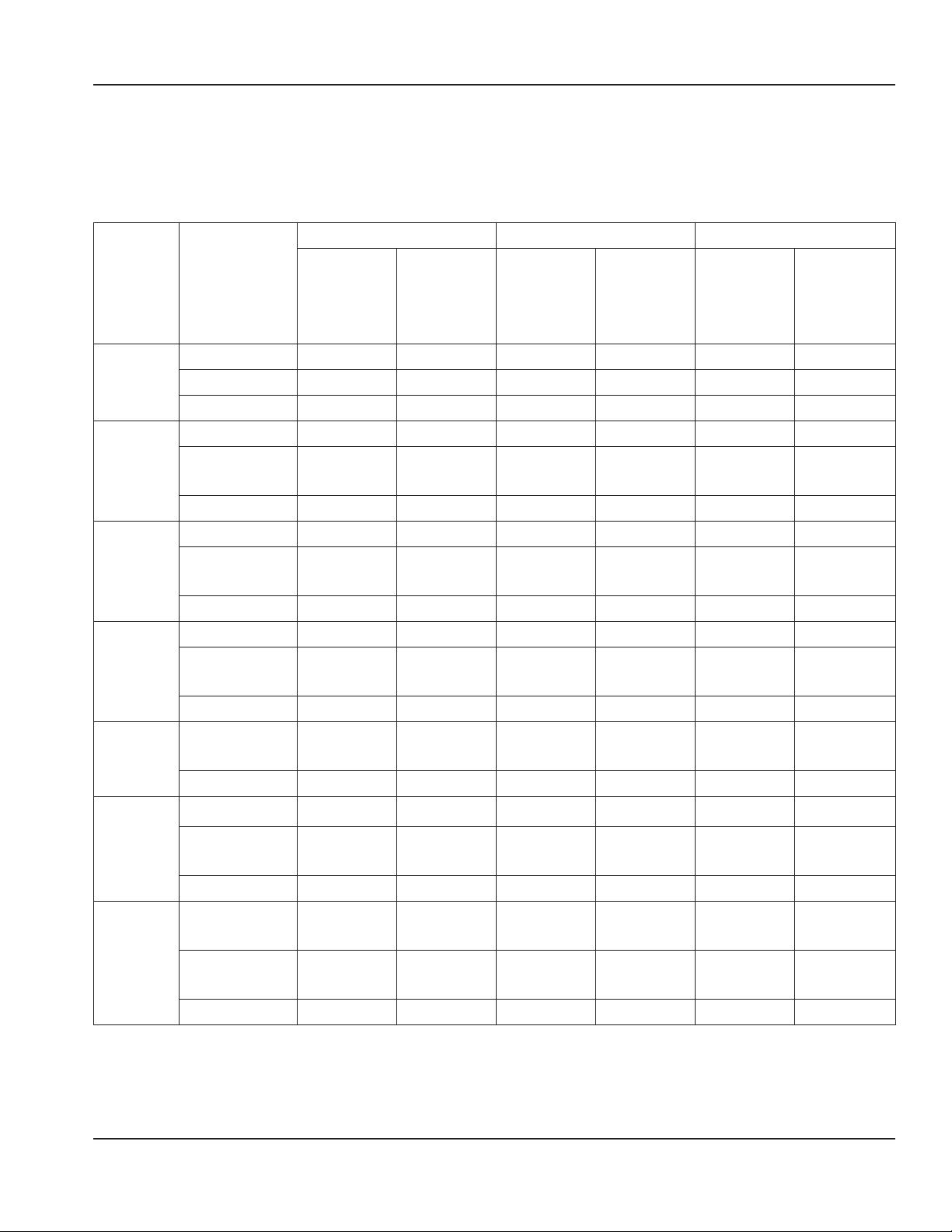
Maximum Breaker Size & Minimum Circuit Amperage Chart
NOTE: Due to continuous product improvements, this information is for reference only.
Please refer to the ice machine data plate to verify electrical data. Data plate information
overrides information listed on this page.
Ice
Machine
Voltage/
Phase/Cycle
Air-Cooled Water-Cooled Remote Condenser
Maximum
Fuse/
Circuit
Breaker
Minimum
Circuit
Amps
Maximum
Fuse/
Circuit
Breaker
Minimum
Circuit
Amps
Maximum
Fuse/
Circuit
Breaker
Minimum
Circuit
Amps
IF0300
115/1/60 15 *10.8 15 *10.0 - - - - - -
230/1/50 15 *6.1 15 *5.6 - - - - - -
230/1/60 15 *6.1 15 *5.7 - - - - - -
IT0420
115/1/60 15 11.3 15 10.6 - - - - - -
208-230/
1/60
15 5.5 15 5.2 - - - - - -
230/1/50 15 5.7 - - - - - - - - - - - -
IT0450
115/1/60 20 11.9 20 11.2 - - - - - -
208-230/
1/60
15 5.6 15 5.3 - - - - - -
230/1/50 15 5.6 15 5.3 - - - - - -
IT0500
115/1/60 15 11.5 15 10.8 20 13.7
208-230/
1/60
15 5.1 15 4.8 - - - - - -
230/1/50 15 5.6 - - - - - - - - - - - -
IF0600
208-230/
1/60
15 *11.1 15 *10.7 15 *11.7
230/1/50 15 *6.7 15 *6.1 15 *7.1
IT0620
115/1/60
20 12.2 20 11.6 - - - - - -
208-230/
1/60
15 5.9 15 5.6 - - - - - -
230/1/50 15 5.6 15 5.4 - - - - - -
IF0900
208-230/
1/60
20 *12.2 20 *11.2 20 *12.2
208-230/
3/60
15 *9.7 15 *8.7 15 *9.7
230/1/50 20 *12.2 20 *11.2 15 *12.2
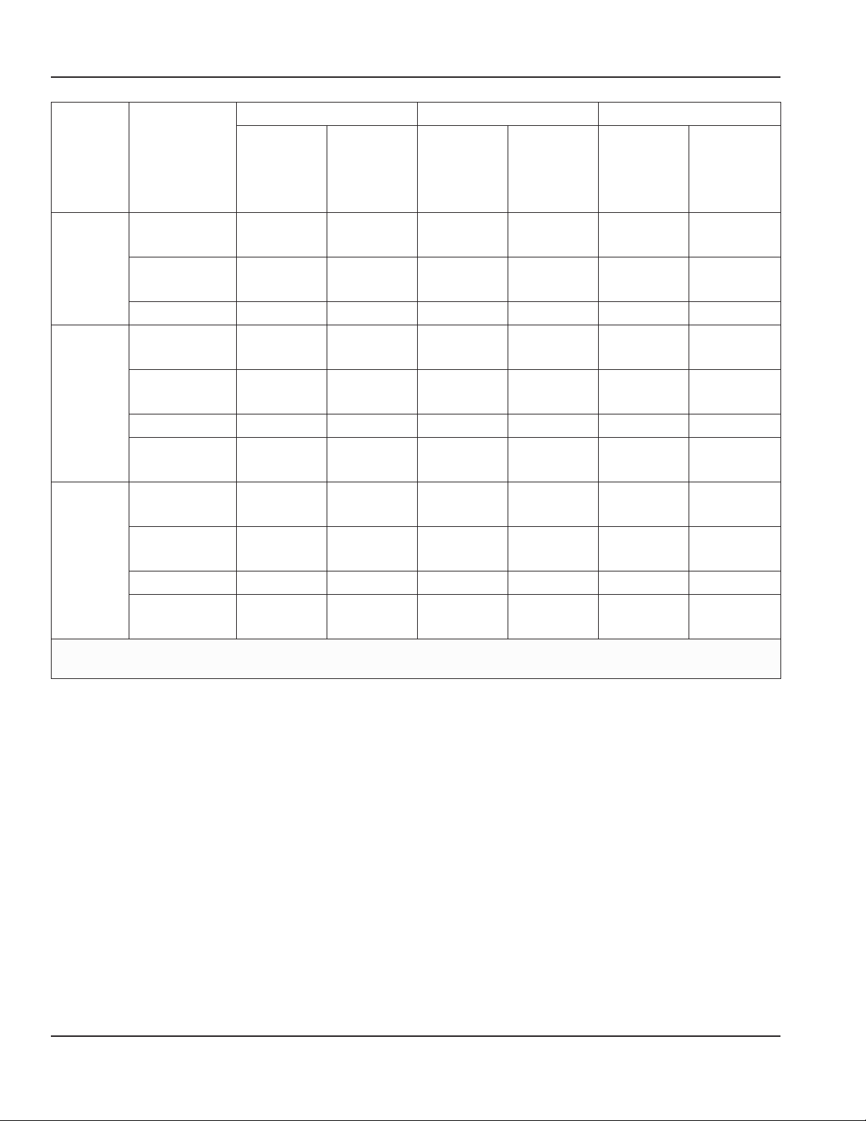
18 Part Number: 000014141 Rev 03 2/18
Installation Section 2
Ice
Machine
Voltage/
Phase/Cycle
Air-Cooled Water-Cooled Remote Condenser
Maximum
Fuse/
Circuit
Breaker
Minimum
Circuit
Amps
Maximum
Fuse/
Circuit
Breaker
Minimum
Circuit
Amps
Maximum
Fuse/
Circuit
Breaker
Minimum
Circuit
Amps
IT1200
208-230/
1/60
20 14.2 20 13.4 15 11.0
208-230/
3/60
15 8.6 15 7.9 15 9.2
230/1/50 20 14.0 20 13.3 15 11.1
IT1500
208-230/
1/60
25 15.4 25 14.0 25 14.0
208-230/
3/60
20 12.8 20 11.3 20 11.3
230/1/50 25 14.9 25 14.2 25 15.2
380-460/
3/50-60
- - - - - - 15 *6.4 - - - - - -
IT1900
208-230/
1/60
30 17.9 25 16.5 25 17.0
208-230/
3/60
20 14.2 20 12.8 20 13.0
230/1/50 25 15.8 25 15.0 25 15.3
380-460/
3/50-60
- - - - - - 15 *6.5 - - - - - -
* Data marked with an asterisk is preliminary and subject to change - Model/serial plate information
overrides all data listed in this chart.
Part Number: 000014141 Rev 03 2/18 19
Section 2 Installation
QuietQube Head Sections
Ice Machine
Voltage/Phase/
Cycle
Maximum Fuse/
Circuit Breaker
Minimum Circuit
Amps
Total Amps
Ice Beverage
Models
115/1/60 15 amp - - - 1.2
230/1/50 15 amp - - - 1.2
All Non IB
QuietQube
Models
115/1/60 15 amp 1.2 - - -
230/1/50 15 amp 1.2 - - -
CVD Condensing Units
Condensing
Unit
Voltage/Phase/
Cycle
Maximum
Fuse/Circuit
Breaker
Minimum
Circuit Amps
Minimum Wire Size Required
by Manitowoc
CVDF0600
208-230/1/60 15 amp *11.6 #12 Solid Copper Conductor
208-230/3/60 15 amp *10.2 #12 Solid Copper Conductor
230/1/50 15 amp *10.2 #12 Solid Copper Conductor
CVDF0900
208-230/1/60 20 amp *12.5 #10 Solid Copper Conductor
208-230/3/60 15 amp *9.5 #12 Solid Copper Conductor
230/1/50 20 amp *12.5 #10 Solid Copper Conductor
CVDT1200
208-230/1/60 25 amp 14.8 #10 Solid Copper Conductor
208-230/3/60 15 amp 9.3 #12 Solid Copper Conductor
CVDF1400
208-230/1/60 20 amp *11.7 #10 Solid Copper Conductor
208-230/3/60 15 amp *8.9 #12 Solid Copper Conductor
CVDF1800
208-230/1/60 40 amp *25.0 #8 Solid Copper Conductor
208-230/3/60 25 amp *20.0 #10 Solid Copper Conductor
230/1/50 40 amp *25.0 #8 Solid Copper Conductor
CVDF2100
208-230/1/60 50 amp *40.0 #6 Solid Copper Conductor
208-230/3/60 30 amp *30.0 #10 Solid Copper Conductor
* Data marked with an asterisk is preliminary and subject to change - Model/serial plate information
overrides all data listed in this chart.
20 Part Number: 000014141 Rev 03 2/18
Installation Section 2
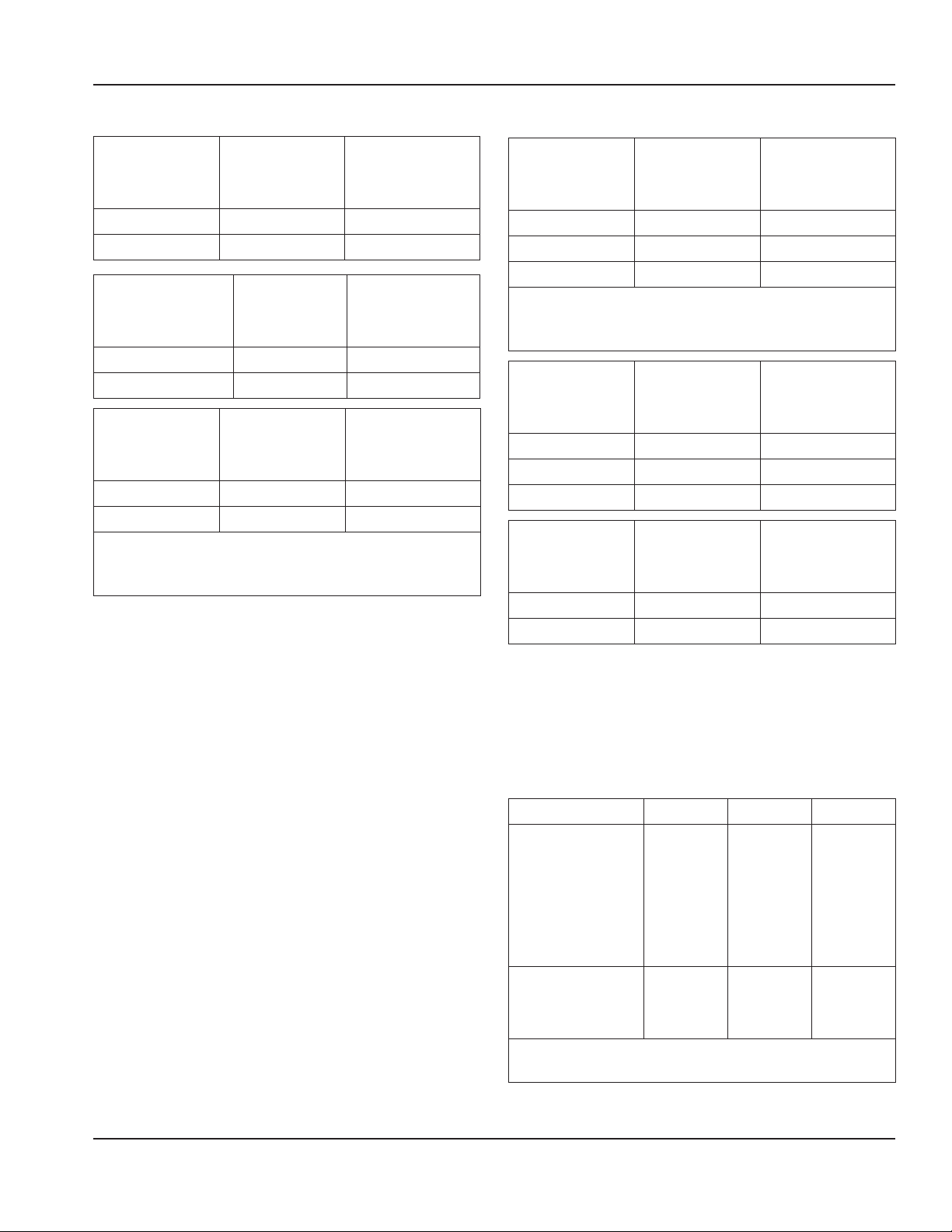
Water Supply and Drain Line Sizing/Connections
,
Caution
Do not apply heat to water inlet valve or water drain fittings. Heating will damage the
nonmetallic connector. Do not over tighten fittings. Two turns after hand tight is the
maximum.
• Local water conditions may require treatment of the water to inhibit scale formation,
filter sediment, and remove chlorine odor and taste.
• Connect ice making water inlet to potable water only.
• Do not connect to hot water supply.
• Install a water shut-off valve.
• Insulate water and drain lines to prevent condensation.
Location
Water
Temperature
Water Pressure
Ice Machine
Fitting
Tubing Size up
to Ice Machine
Fitting
Ice Making
Water Inlet
40°F (4.4°C) Min.
90°F (32°C) Max.
20 psi (140 kPa)
Min.
80 psi (550 kPa)
Max.
3/8" Female Pipe
Thread
3/8" (10 mm)
minimum inside
diameter
Ice Making
Water Drain
— —
1/2" Female Pipe
Thread
1/2" (13 mm)
minimum inside
diameter
Condenser Water
Inlet
40°F (4.4°C) Min.
90°F (32°C) Max.
20 psi (140 kPa)
Min.
150 psi
(1030 kPa) Max.
I0300 - I1000 = 3/8"
Female Pipe Thread
I1200 - I1800 = 1/2"
Female Pipe Thread
Condenser Water
Drain
— —
1/2" Female Pipe
Thread
1/2" (13 mm)
minimum inside
diameter
Bin Drain — —
3/4" Female Pipe
Thread
3/4" (19 mm)
minimum inside
diameter
Large Capacity
Bin Drain
1" Female Pipe
Thread
1" (25 mm)
minimum inside
diameter
Min. = Minimum, Max. = Maximum
Part Number: 000014141 Rev 03 2/18 21
Section 2 Installation
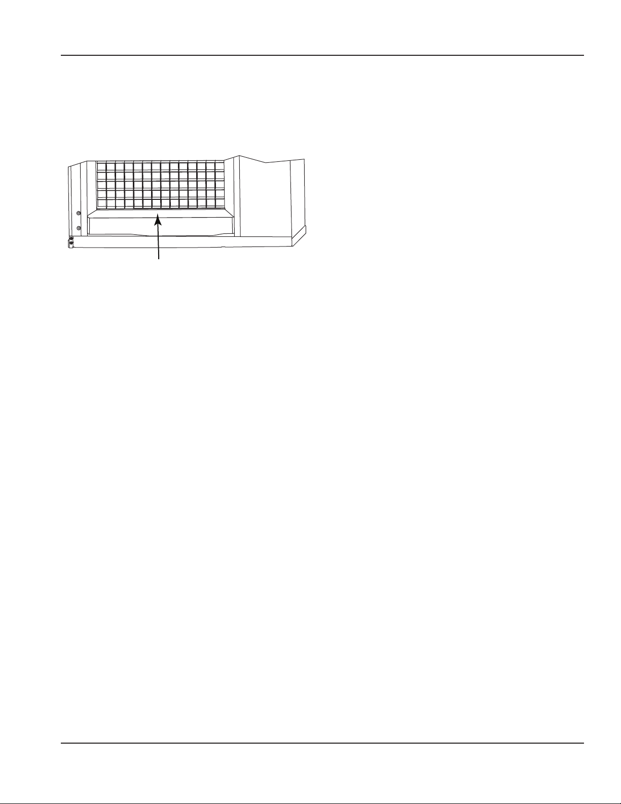
Air Gap
A greater than 1-inch air gap is built into
the ice machine for back-flow prevention.
This air gap exceeds NSF 12 requirements
for back-flow prevention.
Cooling Tower Applications
(Water-Cooled Models)
A water cooling tower installation does not
require modification of the ice machine.
• Water pressure at the condenser cannot
exceed 150 psig (1034 kPa). A special
order unit is available that allows water
pressure up to 350 psig (2413 kPa).
• Water entering the condenser must not
exceed 90°F (32°C).
• Water flow through the condenser
must not exceed 5 gallons (19 liters) per
minute.
• Allow for a pressure drop of 7 psi
(50 kPa) between the condenser water
inlet and the outlet of the ice machine.
• Water exiting the condenser must not
exceed 110°F (43°C).
Drain Connections
Follow these guidelines when installing
drain lines to prevent drain water from
flowing back into the ice machine and
storage bin:
• Drain lines must have a of run 1.5 inch
drop per 5 feet (2.5 cm per meter) and
must not create traps.
• The floor drain must be large enough to
accommodate drainage from all drains.
• Run separate bin and ice machine
drain lines. Insulate them to prevent
condensation.
• Vent the ice machine drain to the
atmosphere.
• Drain termination must have an air gap
that meets local code.
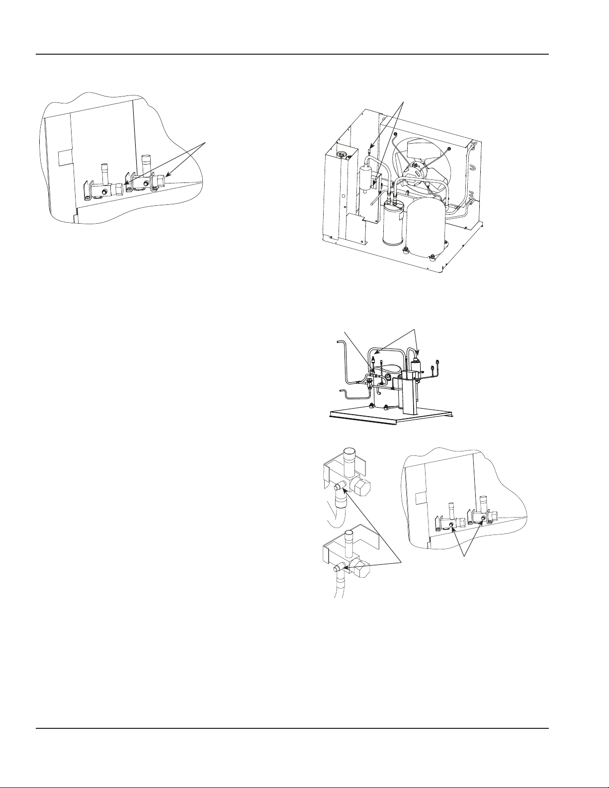
Auxiliary Base Drain Installation
An auxiliary drain is located in the ice
machine base to remove moisture in high
humidity areas.
1. View the back of the ice machine base
on the compressor side and locate and
remove the cap plug.
2. Route tubing to an open site drain:
• Use 1/2 inch CPVC tubing.
• Apply a bead of silicone around the
exterior of the ice machine tubing
and insert into ice machine base. The
silicone will secure the tubing and
provide a watertight seal.
• Provide support for tubing.
This air gap is greater than 1"
22 Part Number: 000014141 Rev 03 2/18
Installation Section 2
Remote Condenser and Condensing Unit Refrigeration System Installation
Each ice machine head section ships from the factory with a refrigerant charge
appropriate for the entire system operation. The serial tag on the ice machine indicates
the refrigerant charge.
QuietQube® Ice
Machine
Remote Condenser Line Set*
Additional Refrigerant
Charge for 50' to 100'
(15 to 30 Meter) Line Sets
IF0600C
IBF0620C
CVDF0600
RC-21
RC-31
RC-51
1.5 lbs - 680 g
IBF0820C
IF0900C
CVDF0900 2 lbs - 907 g
IBT1020C CVDT1200 2 lbs - 907 g
IT1200C CVDT1200 2 lbs - 907 g
IF1400C CVDF1400 RC-20
RC-30
RC-50
2 lbs - 907 g
IF1800C CVDF1800 2 lbs - 907 g
IF2100C CVDF2100
RC-23
RC-33
RC-53
4 lbs - 1814 g
*Line Set Suction Line Liquid Line Minimum Insulation Thickness
RC 21/31/51
5/8 inch
16 mm
3/8 inch
10 mm
1/2" (13 mm) Suction Line
1/4" (7 mm) Liquid Line
RC 20/30/50
3/4 inch
19 mm
1/2 inch
13 mm
1/2" (13 mm) Suction Line
1/4" (7 mm) Liquid Line
RC 23/33/53
3/4 inch
19 mm
5/8 inch
16 mm
1/2" (13 mm) Suction Line
1/4" (7 mm) Liquid Line
n
Warning
Installation of a QuietQube® Condensing
Unit may require the use of special
equipment for placement. Trained and
qualified personnel are required for proper
rigging and lifting. Holes are provided on
the corners of the condensing unit to allow
the use of lifting shackles.
Important
Manitowoc remote systems are only
approved and warranted as a complete
new package. Warranty on the refrigeration
system will be void if a new ice machine
head section is connected to pre-existing
(used) tubing or condensing units or vice
versa.

Part Number: 000014141 Rev 03 2/18 23
Section 2 Installation
Remote Condenser Models
Ice
Machine
Remote
Condenser
Additional Amount
of Refrigerant
to Be Added to
Nameplate Charge
for 50' to 100'
(15 to 30 Meter)
Line Sets
IT0500N JCT0500 1.5 lbs - 680 g
IF0600N JCT0900 1.5 lbs - 680 g
IF0900N JCT0900 2 lbs - 907 g
IT1200N JCT1200 2 lbs - 907 g
IT1500N JCT1500 2 lbs - 907 g
IT1900N JCT1500 2 lbs - 907 g
Line Set
Discharge
Line
Liquid
Line
Model
RT
20/35/50
R404A
1/2 inch
13 mm
5/16 inch
7.9 mm
iF0600N
iF0900N
RT
20/35/50
R410A
1/2 inch
13 mm
5/16 inch
7.9 mm
iT0500N
iT1200N
RL
20/35/50
R410A
1/2 inch
13 mm
3/8 inch
9.5 mm
iT1500N
iT1900N
NOTE: R404A line sets have white
protective caps and R410A line sets have
pink protective caps.
n
Warning
Potential Personal Injury Situation
The ice machine head section contains
the refrigerant charge. Installation and
brazing of the line sets must be performed
by a properly trained and EPA certified
refrigeration technician aware of the
dangers of dealing with refrigerant charged
equipment.
CALCULATING INSTALLATION DISTANCES
Line Set Length
The maximum tubing length is 100 feet (30
meters).
Line Set Rise/Drop
The maximum rise is 35 feet (10.7 meters).
The maximum drop is 15 feet (4.5 meters).
Notice
If a line set has a rise followed by a drop,
another rise cannot be made. Likewise,
if a line set has a drop followed by a rise,
another drop cannot be made.
Calculated Line Set Distance
The maximum calculated distance is 150
feet (45 meters).
Line set rises, drops, horizontal runs (or
combinations of these) in excess of the
stated maximums will exceed compressor
start-up and design limits. This will cause
poor oil return to the compressor. Make the
following calculations to make sure the line
set layout is within specifications.
1. Insert the measured rise into the
formula below. Multiply by 1.7 to get
the calculated rise.
2. Insert the measured drop into the
formula below. Multiply by 6.6 to get
the calculated drop.
3. Insert the measured horizontal
distance into the formula below. No
calculation is necessary.

24 Part Number: 000014141 Rev 03 2/18
Installation Section 2
4. Add together the calculated rise,
calculated drop, and horizontal
distance to get the total calculated
distance. If this total exceeds 150 feet
(45 meters), move the condenser/
condensing unit to a new location and
perform the calculations again.
Maximum Line Set Distance Formula
Step 1.
Measured Rise (R) 35 feet (10.7 meters)
Maximum _____ x 1.7 =
_____ Calculated Rise
Step 2.
Measured Drop (D) 15 feet (4.5 meters)
Maximum _____ x 6.6 =
_____ Calculated Drop
Step 3.
Measured Horizontal Distance (H) 100 feet
(30 meters) Maximum
_____ Horizontal Distance
Step 4.
Total Calculated Distance 150 feet (45
meters) Maximum
_____ Total Calculated
Distance
Notice
The refrigeration system warranty will
not apply if the Manitowoc Ice Machine
and Manitowoc CVD Condensing Unit are
not installed according to specifications.
This warranty also will not apply if the
refrigeration system is modified with a
condenser, heat reclaim device, or other
parts or assemblies not approved by
Manitowoc.
REMOTE CONDENSER MODELS
Step 1 Secure the Condenser.
Through-holes are provided to secure
the condenser to a curb, rack or wooden
timber.
n
Warning
The ice machine head section contains
refrigerant charge. The ice machine head
section contains refrigeration valves
that must remain closed until proper
installation of the line sets is completed.
n
Warning
Electrical power to the ice machine head
section, condensing unit or condenser
must be disconnected before proceeding.
Step 2 Route the Refrigeration Tubing.
Route the refrigeration tubing between
the ice machine head section and the
condenser.
• Maximum line set exposed on rooftop is
25% of total line set length.
• A qualified person must perform all roof
penetrations.
Step 3 Connect the Line Set.
In most cases, by routing the line set
properly, shortening will not be necessary.
When shortening or lengthening is
required, do so before connecting the
line set to the ice machine or the remote
condenser. This prevents the loss of
refrigerant in the ice machine or condenser.
The quick connect fittings on the line sets
are equipped with access valves. Use these
valves to recover any vapor charge from the
line set.

Part Number: 000014141 Rev 03 2/18 25
Section 2 Installation
When lengthening or shortening lines,
follow good refrigeration practices, purge
with nitrogen and insulate all tubing. Do
not change the tube sizes. Evacuate the
lines and place about 5 oz (145 grams) of
vapor refrigerant charge in each line.
1. Remove the dust caps from the line
set, condenser and ice machine.
2. Apply refrigeration oil to the threads
on the quick-disconnect couplers
before connecting them to the
condenser.
3. Carefully thread the female fitting to
the condenser or ice machine by hand,
then tighten the couplings with a
wrench until they bottom out.
4. Turn an additional quarter turn to
ensure proper brass-to-brass seating.
Torque to the following specifications:
Liquid Line Discharge Line
10 - 12 ft lbs
13.5-16.2 N•m
35 - 45 ft lbs
47.5-61.0 N•m
5. Check all fittings and valve caps for
leaks and reinstall and tighten caps.
6. The receiver service valve is closed
during shipment and must be opened
before starting the ice machine.
A. Remove the receiver service valve
cap.
B. Backseat (open) the valve.
C. Reinstall the cap and panels.
Installation is finished for remote
condenser models. Proceed to page 29
for start-up procedure.
QUIETQUBE MODELS
Step 1 Secure the Condensing Unit.
Through-holes are provided to secure the
condensing unit to a curb, rack or wooden
timber.
Step 2 Route the Refrigeration Tubing.
Route the refrigeration tubing between
the ice machine head section and the
condenser or CVD condensing unit.
• A suction line oil trap is required when
rise is more than 20 feet (6 meters).
• Only one trap is allowed in the line set.
• Shorten the line set as required, do not
coil line set.
Manitowoc S-Trap Kit
Model
S-Trap Kit
Number
Tubing
Size
IBF0620C IBF0820C
IBT1020C
IF0600C IF0900C
IT1200C
K00172
5/8 inch
(16 mm)
IF1400C IF1800C
IF2100C
K00166
3/4 inch
(19 mm)
• Maximum amount of time the
refrigeration system can be exposed to
the atmosphere is 15 minutes.
• Purge line set with dry nitrogen while
brazing.
• Shutoff valves for the line set on the ice
machine must remain closed and be
protected from heat during brazing.
• The condensing unit ships with a 50/50
mixture of nitrogen/helium.
26 Part Number: 000014141 Rev 03 2/18
Installation Section 2
VALVES MUST
REMAIN CLOSED AND
BE PROTECTED FROM
HEAT WHEN BRAZING
(WRAP WITH WET
RAG)
Step 3 Pressure Test and Evacuate Line Set
and CVD Condensing Unit.
• Shutoff valves for the line set must
remain closed until pressure testing and
evacuation are complete.
• Valve core removal tools that allow for
removal and installation of the valve
cores without removing hoses for the
manifold gauge set are recommended to
decrease the evacuation time.
• Pressure test at 150 psi (1000 kPa) for a
minimum of 15 minutes.
• Minimum evacuation level is 500
microns.
Pressure test the line sets and CVD
Condensing Unit with 150 psi (1000 kPa) of
dry nitrogen. Add nitrogen at the shutoff
valves for the line set located at the back
of the ice machine head section or from
the access valves located in the CVD
Condensing Unit. Complete the pressure
test, verify no leaks are present and remove
the nitrogen from the system before
connecting the vacuum pump. Connect
vacuum pump and evacuate system to 500
microns.
ALTERNATE CONNECTIONS
AT CONDENSING UNIT
SCHRADER VALVES
CONNECT MANIFOLD GAUGE
SET OR HOSE WITH CORE
DEPRESSORS ON BOTH ENDS
CHECK
VALVE
CONDENSER
LINE SET CONNECTION
LOCATION
CONNECT VACUUM
PUMP TO SHUTOFF
VALVES FOR THE LINE SET
Part Number: 000014141 Rev 03 2/18 27
Section 2 Installation
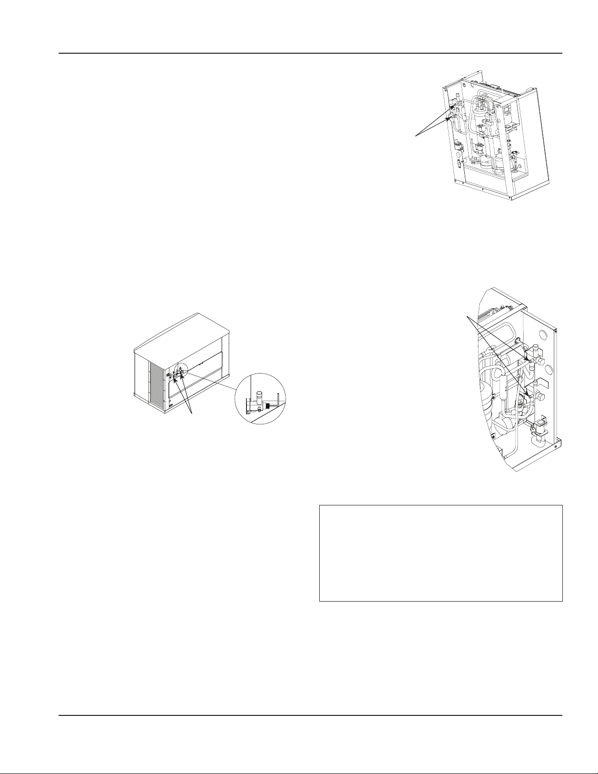
Step 4 Open Valves for the Line Set and
Receiver.
You will not hear refrigerant flow when the
valves are opened. Refrigerant will not flow
until the ice machine is started and the
solenoid valve opens.
• All valve caps must be reinstalled,
tightened and leak-checked to assure no
refrigerant leakage exists.
• Counterclockwise opens all valves:
A. Open the shutoff valves for the
suction and liquid lines.
B. Open the receiver service valve
until back seated (when used).
USE ALLEN WRENCH TO OPEN
(TURN COUNTERCLOCKWISE)
SHUTOFF VALVES FOR THE LIQUID
AND SUCTION LINES
QuietQube Models
USE ALLEN WRENCH
TO OPEN (TURN
COUNTERCLOCKWISE)
SHUTOFF VALVES
FOR THE LIQUID AND
SUCTION LINES
Ice Beverage Models
USE ALLEN WRENCH TO OPEN
(TURN COUNTERCLOCKWISE)
SHUTOFF VALVES FOR THE
LIQUID AND SUCTION LINES
IF1400C/IF1800C/IF2100C
Notice
After opening suction, discharge and
receiver service valves, refrigerant
pressure will not be detected until the
ice machine starts a freeze cycle and the
solenoid valves energize.

28 Part Number: 000014141 Rev 03 2/18
Installation Section 2
Step 5 Leak-Check the Refrigeration
System.
A. Connect power to the ice machine
head section - Do not connect
power to the CVD condensing unit.
B. Press the power switch and
energize the ice machine for 60
seconds to equalize pressures.
C. Disconnect power to the ice
machine head section.
D. Leak-check line set connections, S
trap and all factory joints in head
section and condensing unit.
E. Connect power to the CVD
condensing unit and allow system
to pump down.
Step 6 Insulation Requirements
• To prevent condensation, the entire
suction line, including the shutoff valve,
must be insulated.
• All insulation must be airtight and sealed
at both ends.
The following insulation requirements
prevent condensation at 90° F (32°C)
ambient temperature and 90% relative
humidity. If higher humidity is expected,
increase insulation thickness:
Suction
Line
Liquid
Line
Min. Insulation
Thickness
3/4 inch
19 mm
1/2 inch
13 mm
Suction Line -
1/2" (13 mm)
Liquid Line -
1/4" (7 mm)
5/8 inch
16 mm
3/8 inch
10 mm
3/4 inch
19 mm
5/8 inch
16 mm
Suction Line -
3/4" (19 mm)
Liquid Line -
1/4" (7 mm)
Step 7 Insulation for the Suction Shutoff
Valve
The insulation for the suction shutoff valve
is located in the plastic bag taped to the
water curtain.
Step 8 Ice Beverage Models Only
The thermostat probe must be moved from
the shipping position to the ice-making
position.
• The bin thermostat probe must be
rotated down to enable ice contact and
proper operation.
• Verify probe wire does not interfere with
the water curtain.
• The control is preset and does not
require programming.
1. Loosen thumbscrew securing probe.
2. Rotate the probe from horizontal to
vertical position.
3. Tighten thumbscrew to secure probe.
Part Number: 000014141 Rev 03 2/18 29
Section 2 Installation
Starting the Ice Machine
Starting the ice machine and completing
the Operational Checks are the
responsibilities of the owner/operator.
Adjustments and maintenance procedures
outlined in this manual are not covered by
the warranty.
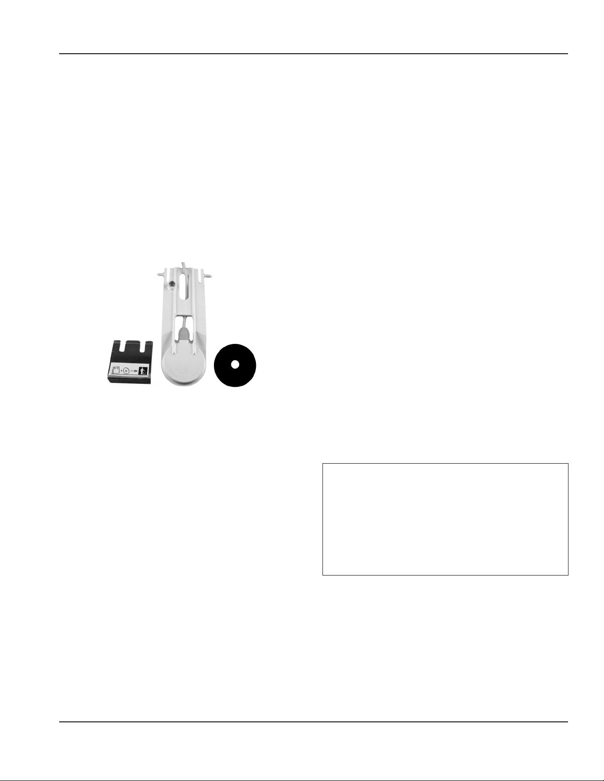
REMOVE ICE THICKNESS PROBE
SHIPPING BRACKETS.
Remove and discard shipping brackets
before starting the ice machine.
Step 1 Ice machine must be programmed
refer to “Touch Screen Features” on page
31 for details.
Step 2 Refer to “Cleaning/Sanitizing
Procedure” on page 40 and sanitize
the ice machine and bin before placing in
operation.
Step 3 Refer to “Ice Making Sequence of
Operation” on page 35 for operational
details.
MINIMUM/MAXIMUM SLAB WEIGHT
Adjust ice thickness to maintain the correct
bridge thickness and “Minimum/Maximum
Slab Weight” on page 37.
Remote Ice Machine Usage with Non-
Manitowoc Multi-Circuit Condensers
Warranty
The sixty (60) month compressor warranty,
including thirty six (36) month labor
replacement warranty, shall not apply when
the remote ice machine is not installed
within the remote specifications. The
foregoing warranty shall not apply to any
ice machine installed and/or maintained
inconsistent with the technical instructions
provided by Manitowoc Ice. Performance
may vary from Sales specifications. ARI
certified standard ratings only apply when
used with a Manitowoc remote condenser.
If the design of the condenser meets the
specifications, Manitowoc’s only approval
is for full warranty coverage to be extended
to the Manitowoc manufactured part of
the system. Since Manitowoc does not
test the condenser in conjunction with the
ice machine, Manitowoc will not endorse,
recommend, or approve the condenser, and
will not be responsible for its performance
or reliability.
Important
Manitowoc warrants only complete
new and unused remote packages.
Guaranteeing the integrity of a new ice
machine under the terms of our warranty
prohibits the use of pre-existing (used)
tubing or condensers.
30 Part Number: 000014141 Rev 03 2/18
Installation Section 2
Design & Burst Pressure
Design Pressure 600 psig - 4137 kPa
Burst Pressure 2500 psig - 17237 kPa
Head Pressure Control Valve
Do not use a fan cycling control to try to
maintain discharge pressure. Compressor
failure will result. Any remote condenser
connected to a Manitowoc Ice Machine
must have the OEM head pressure control
valve installed. Manitowoc will not accept
substitute “off the shelf” head pressure
control valves.
Fan Motor
The condenser fan must be on during the
complete ice machine freeze cycle (do
not cycle on fan cycle control). The ice
maker has a condenser fan motor circuit
for use with a Manitowoc condenser. It is
recommended that this circuit be used to
control the condenser fan(s) on the multi-
circuit condenser to assure it is on at the
proper time. Do not exceed the rated amps
for the fan motor circuit listed on the ice
machine’s serial tag.
Internal Condenser Volume
The multi-circuit condenser internal
volume must not be less than or exceed
that used by Manitowoc. Do not exceed
internal volume and try to add charge to
compensate, as compressor failure will
result.
Model Minimum Maximum
IT0500N 0.020 0.030
IF0600N/IF0900N
IT1200N
0.045 0.060
IT1500N/IT1900N 0.085 0.105
Heat of Rejection
Model Peak Average
IT0500N 6100 6900
IF0600N 9000 13900
IF0900N 13000 1600
IT1200N 20700 24500
IT1500N 23000 27000
IT1900N 26100 30500
Refrigerant Charge
The ice machine model/serial tag lists the
refrigerant amount. Remote condensers
and line sets contain a vapor charge only.
Model Amount Type
IT0500N 6.0 lbs - 2.72 kg R410A
IF0600N *6.5 lbs - 2.95 kg R404A
IF0900N *7 lbs - 3.18 kg R404A
IT1200N 7.5 lbs - 3.40 kg R410A
IT1500N 8.0 lbs - 3.63 kg R410A
IT1900N 8.0 lbs - 3.63 kg R410A
*Data marked with an asterisk is preliminary and subject to change - Model/serial
plate information overrides all data listed in this chart.
Quick Connect Fittings
The ice machine and line sets come with
quick connect fittings. It is recommended
that matching quick connects (available
through Manitowoc Distributors K00129)
be installed in the multi-circuit condenser,
and that a vapor “holding” charge, 5 oz.
(150 ml), of proper refrigerant be added to
the condenser prior to connection of the
ice machine or line set to the condenser.
Part Number: 000014141 Rev 03 2/18 31
S
i
MAKING ICE
3
3
4/17/2018 11:12 AM
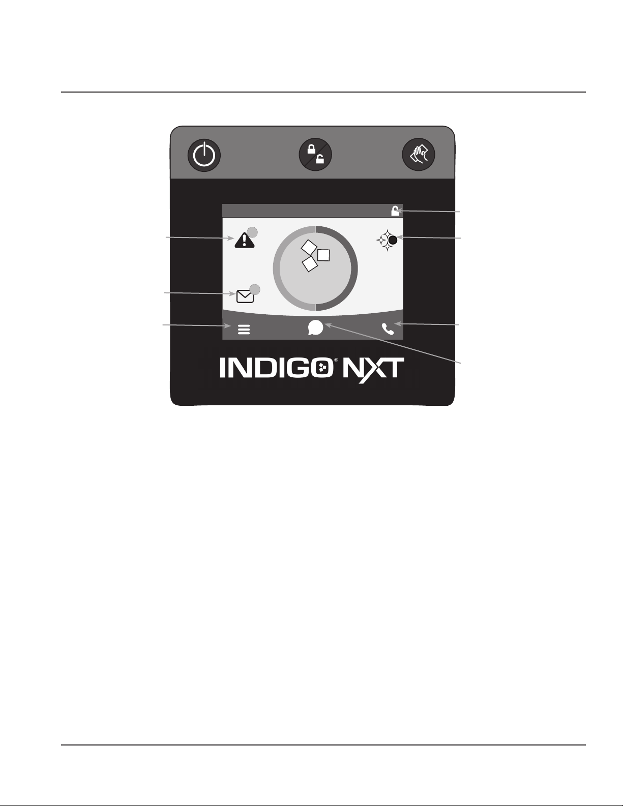
Information
Power Button
Menu Icon
Lock/Unlock Screen
Cleaning Button
Screen Locked or
Unlocked
Service Locater
LuminIce
Touch Screen Features
The Indigo® control panel offers a series
of pressure-sensitive buttons and an
interactive touchscreen.
Buttons
Power Button: Provides On/Off functions
for the ice machine.
Lock/Unlock Button: Allows or prevents
touchscreen navigation.
Cleaning Button: Initiates a cleaning cycle.
Refer to Section 4 for details.
Touchscreen
Home screen allows viewing of ice machine
status, alerts and messages. Navigation
with the touchscreen provides access to
menu items, machine information, settings
and event logs. Setup and Energy Saver
settings can be adjusted along with access
to service and troubleshooting information.
NOTE: Touchscreen is to be activated with
finger tips only.
Icons: Provide status indication and allow
navigation by pressing the icon.
Section 3
Operation
Notification Icon
Alert Icon
32 Part Number: 000014141 Rev 03 2/18
Operation Section 3
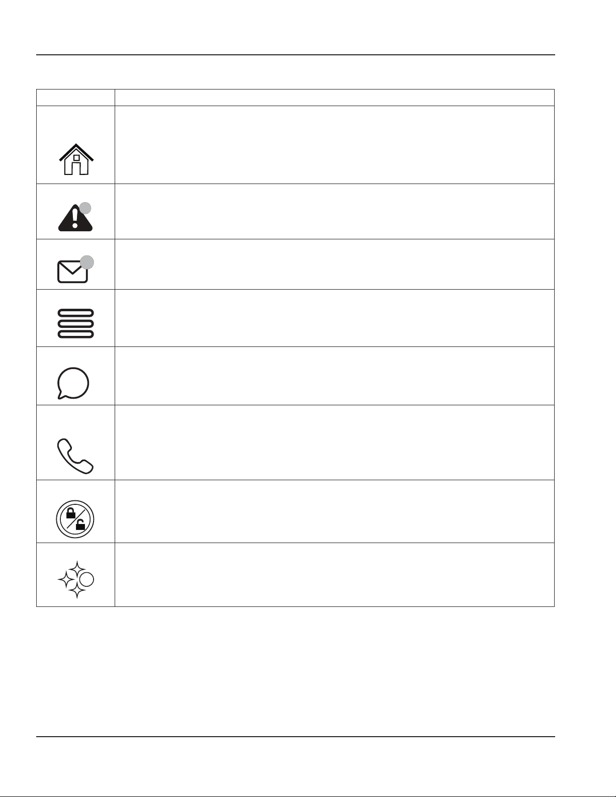
HOME SCREEN ICON DESCRIPTIONS
Icon Description
Home
Screen
Center portion of the screen displays the current condition of the ice
machine - Making ice, bin full, program mode or machine off
Alert
Alert icon with number of messages. Pressing this icon will display the alert
log which will allow viewing and resetting of alerts
Message
Notification icon with quantity of messages. Pressing this icon will display
the routine maintenance reminder screen which will allow viewing and
resetting of the reminder
Menu
Menu icon will take you to the main menu
Information
Information icon provides model and serial number, installation date and
other information specific to the ice machine
Service
Locator
Provides contact information for your local service support - Default is the
Manitowoc Ice website service locator
Lock/Unlock
Indicates if screen is locked or unlocked
LuminIce
Only visible when a LuminIce II accessory is connected.
Blue S - Normal operation
Red S - Replace bulb
Red/Blue alternating - Incorrect bulb installed
3
3
i
S
Part Number: 000014141 Rev 03 2/18 33
Section 3 Operation
Setup Wizard
Screens will automatically advance after a
selection is made or press the right arrow
to advance one screen, press left arrow
to go back one screen. All settings can be
accessed and changed without the wizard
by using menu screen navigation.
Setup Description
Press ON/
OFF Button
On/Off button is used to
start/stop ice making.
Enter Model
Number
Only visible if model number
can not be automatically
identified. The ice machine
will not start without model
identification.
Select
Language
Default is English. Scroll to
select a different language.
Start Wizard
Setup wizard will guide ice
machine programming.
Accessory
Detection
Detects if Ice Level Sensor,
LuminIce II or AuCS are
connected.
Checkmark = yes - X = no
USB Setup
Only used when setup
features have been
transferred to a USB drive.
Skip screen by selecting right
arrow.
Configure
Date and
Time
Formats
Select Month/Day/Year or
Day/Month/Year.
Select 12 hour or 24 hour
time format.
Set Time Use arrows to set local time.
Set Date
Use arrows to set date for
your location.
Units Select standard or metric.
Brightness
Configure screen brightness
during normal operation.
Setup Description
Ice Program
Program ice machine run
times or press right arrow to
skip this setup.
Cleaning
Reminder
Set clean or sanitize
reminder or press right
arrow to skip.
IAuCS
Only when
detected
Set frequency of operation
when this accessory is
installed.
Air Filter
Air-cooled
models only
Set to ON for self-contained
air cooled models.
Water Usage
Factory default
or
Use less water for reverse
osmosis systems
or
Use more water to improve
clarity for unfiltered water
Water Filter Select Yes or No.
LuminIce II
Only when
detected
12 month reminder is
automatically set.
Ice Level
Sensor
Only when
detected
Reminder to rotate the
sensor from shipping to
operational position.
Wizard
Complete
Press right arrow or home
icon to return to home
screen.
34 Part Number: 000014141 Rev 03 2/18
Operation Section 3
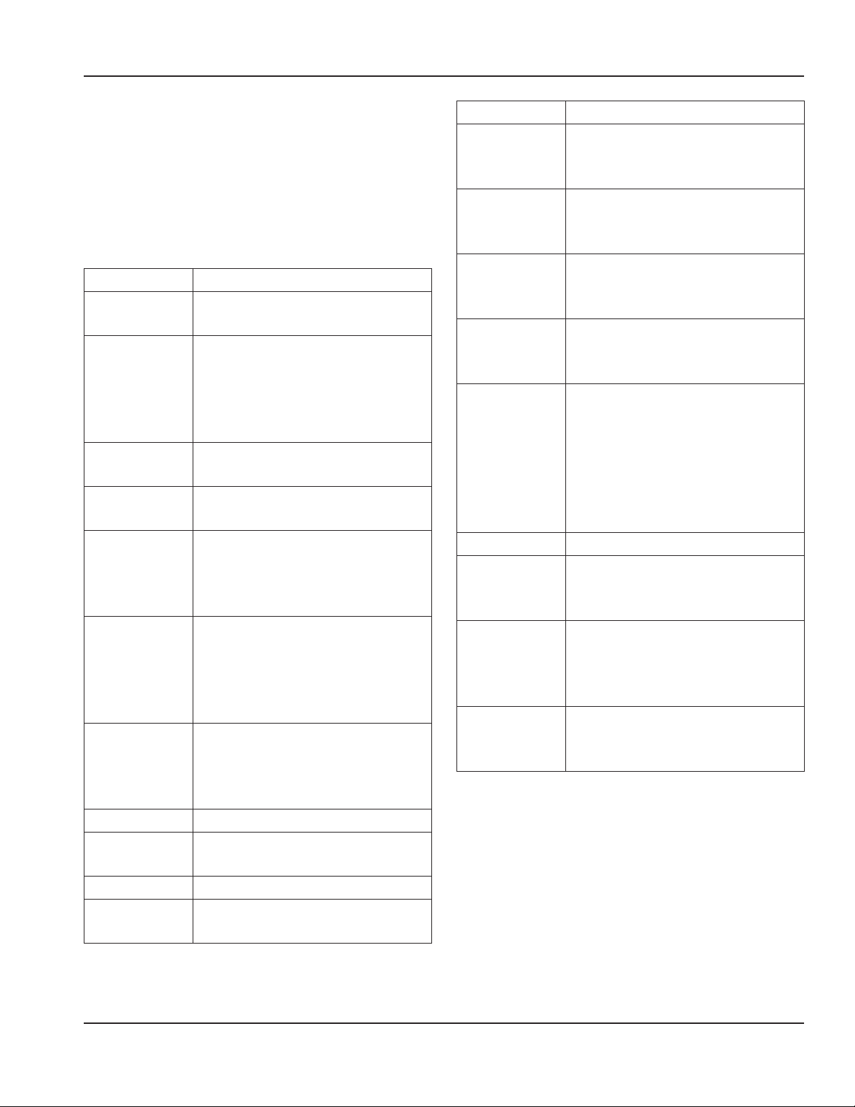
Menu Screen Navigation
Select SETTINGS Icon from the Home Screen to access Main Menu screen.
Energy Service Settings Reset Defaults
Ice Program Data Language
Require Setup
Wizard
Water Usage Alert Log Reminders
Backup Current
Settings
Statistics Manual Harvest Time & Date
Reset To Factory
Defaults
Control Board
Replacement
Units
Diagnostics Brightness
Contact Information USB
USB *AuCS
*AuCS
*Prime AuCS Pump
* Only visible when this optional accessory is installed

Part Number: 000014141 Rev 03 2/18 35
Section 3 Operation
Ice Making Sequence of Operation
The power button must be depressed and
the water curtain/ice dampers must be
in place on the evaporator before the ice
machine will start.
Water Purge Cycle
The ice machine purges any remaining
water from the water trough down the
drain.
Prechill Cycle
The refrigeration system cools the
evaporator before the water pump is
energized.
Freeze Cycle
Water flows across the evaporator and the
refrigeration system chills the evaporator.
Ice builds on the evaporator and the freeze
cycle continues until the ice thickness
probe senses a sheet of ice has formed.
The ice thickness probe signals the control
board to start a harvest.
Harvest Cycle
Any remaining water is purged down
the drain as refrigerant gas warms the
evaporator. When the evaporator warms,
the sheet of cubes slides off the evaporator
and into the storage bin. If all cubes fall
clear of the water curtain (or ice damper)
the ice machine starts another freeze cycle.
Off Cycle
If the water curtain or ice damper are held
open by ice cubes the ice machine shuts
off. When the water curtain or ice damper
closes, the ice machine starts a new cycle at
the water purge.
Control Board Timers
The control board has the following non-
adjustable timers:
• The ice machine control board will set
its own install date after 100 freeze and
harvest cycles.
• The ice machine is locked into the freeze
cycle for 6 minutes before a harvest cycle
can be initiated.
• The maximum freeze time is 35
minutes at which time the control
board automatically initiates a harvest
sequence.
• The maximum harvest time is 7 minutes,
the control board will perform a water
thaw cycle and then return the ice
machine to the freeze cycle.
Service Faults
Service Faults are stored and indicated by
the control board after three cycles. The
number of cycles required to stop the ice
machine varies for each Service Fault.
• Long Freeze Cycle - If the freeze time
reaches 35 minutes, the control board
automatically initiates a harvest cycle.
If 6 consecutive 35 minute freeze cycles
occur, the ice machine stops.
• Long Harvest Cycle - If the harvest time
reaches 7 minutes, the control board
automatically returns the ice machine to
the freeze cycle. After 3 consecutive long
harvest cycles the ice machine stops.
Refer to Section 5 if you receive an alert for
Service Fault E01 or E02.

36 Part Number: 000014141 Rev 03 2/18
Operation Section 3
Safe Operation Mode
Allows the ice machine to operate up to
72 hours if the ice thickness probe and/or
water level probe sensors fail.
• When the control board starts the safe
mode, an alert is flashed on the display
to notify the end-user they have a
production problem.
• The control board automatically initiates
and monitors the safe mode. The control
will automatically exit the safe mode if a
normal signal is received from the input.
• After 72 hours, the control board will
enter a standby mode and turn off.
NOTE: The control board needs a five cycle
history to operate safe mode. If five cycles
have never been successfully completed
the ice machine will shut-off.
Water Assist Harvest
When the damper/curtain does not open
within 3.5 minutes in the harvest cycle the
following occurs:
• 3.5 minutes - The water inlet valve
energizes until water touches the high
water level probe.
• 4 minutes - The water pump energizes.
• 6.5 to 7 minutes - The water dump valve
energizes.
Water Thaw Cycle
When the damper/curtain does not open
during the 7 minute harvest cycle the
following water thaw cycle occurs:
• 7 minutes - The compressor, harvest
solenoid valve and dump valve de-
energize.
1. The water pump remains energized
and the water inlet valve energizes
until water touches the high water
level probe.
2. Water is circulated over the
evaporator.
3. Water is circulated, dumped and
refilled to the high water level probe
for approximately 1 hour.
• At the end of the thaw cycle the ice
machine will start another freeze cycle
(approximately 1 - 1.75 hour).
Part Number: 000014141 Rev 03 2/18 37
Section 3 Operation
Minimum/Maximum Slab Weight
Adjust ice thickness to meet chart
specifications.
Model
Minimum
Ice Weight
Per Cycle
lbs
Grams
Maximum
Ice Weight
Per Cycle
lbs
Grams
IF0300
2.40 lbs
1089 grams
2.80 lbs
1270 grams
IT0420 IT0450
IT0520 IT0620
3.40 lbs
1542 grams
3.90 lbs
1769 grams
IT0500
4.60 lbs
2087 grams
5.20 lbs
2359 grams
IF0600
4.12 lbs
1869 grams
4.75 lbs
2155 grams
IBF0820
5.75 lbs
2608 grams
6.50 lbs
2948 grams
IF0900
6.20 lbs
2812 grams
7.20 lbs
3266 grams
IT1200
IBF1020
7.50 lbs
3402 grams
8.20 lbs
3719 grams
IF1400 IT1500
10.25 lbs
4649 grams
11.50 lbs
5216 grams
IT1900
13.20 lbs
5987 grams
14.80 lbs
6713 grams
IF2100
15.50 lbs
7031 grams
16.75 lbs
7598 grams
Important
Routine adjustments and maintenance
procedures are not covered by the
warranty.
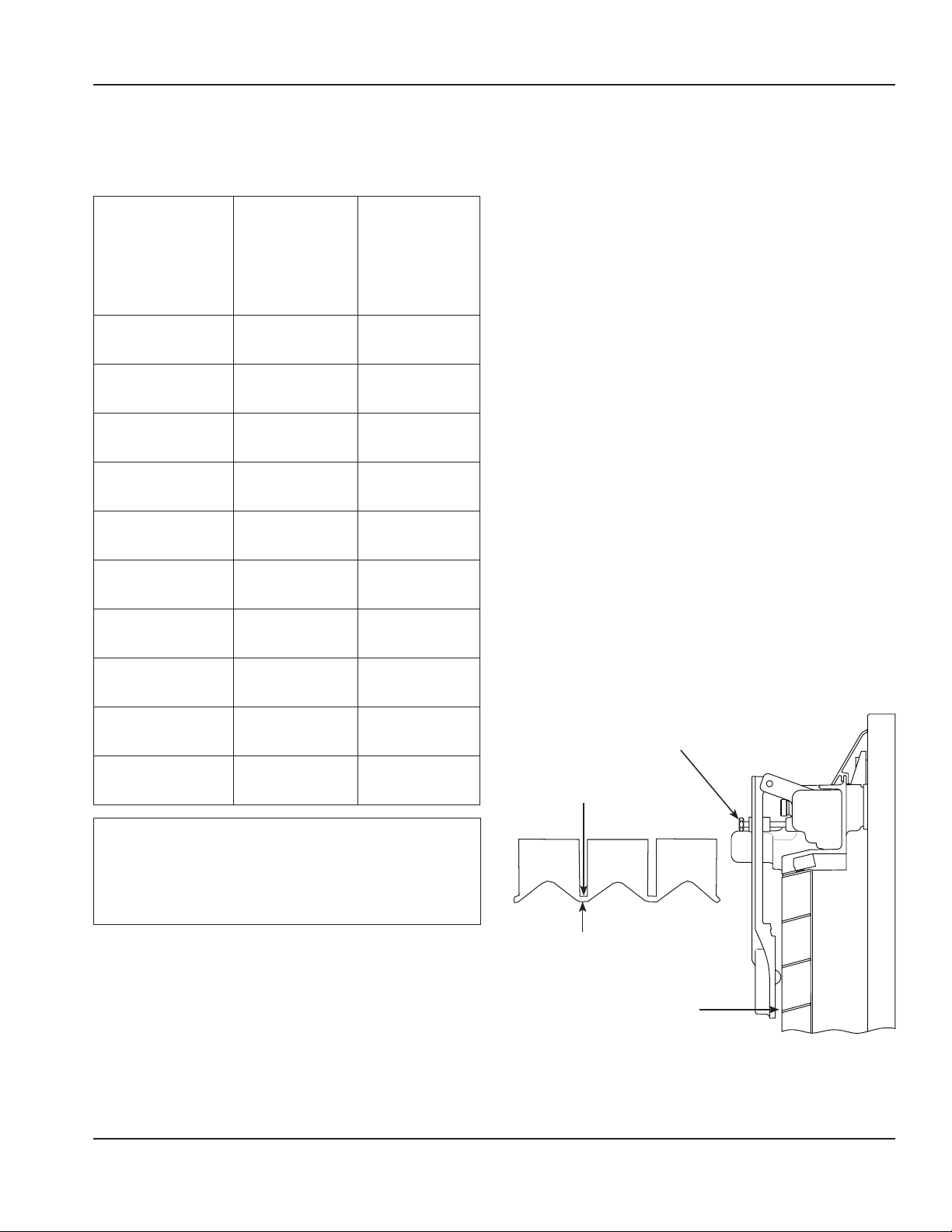
Ice Thickness Check
After a harvest cycle, inspect the ice cubes
in the ice storage bin. The ice thickness
probe is factory-set to maintain the ice
bridge thickness at 1/8" (3 mm).
NOTE: Make sure the water curtain is
in place when performing this check. It
prevents water from splashing out of the
water trough.
1. Inspect the bridge connecting the
cubes. It must be approximately
1/8" (3 mm) thick.
2. If adjustment is necessary, turn the
ice thickness probe adjustment screw
clockwise to increase bridge thickness,
counterclockwise to decrease bridge
thickness. Set a 7 mm (9/32") gap
between ice thickness probe and
evaporator as starting point, then
adjust to achieve a 1/8" (3 mm) bridge
thickness.
NOTE: Turning the adjustment one-third of
a turn will change the ice thickness about
1/16" (1.5 mm).
1/8" (3 mm)
ICE BRIDGE THICKNESS
PLACE 9/32"
(7 mm) DRILL BIT
BETWEEN PROBE AND
EVAPORATOR TO SET
INITIAL GAP
ADJUSTING SCREW
Verify the ice thickness probe wire doesn’t
restrict probe movement.

38 Part Number: 000014141 Rev 03 2/18
Operation Section 3
THIS PAGE INTENTIONALLY LEFT BLANK

Part Number: 000014141 Rev 03 2/18 39
Cleaning and Sanitizing
General
You are responsible for maintaining
the ice machine in accordance with the
instructions in this manual. Maintenance
procedures are not covered by the
warranty.
Clean and sanitize the ice machine every
six months for efficient operation. If the ice
machine requires more frequent cleaning
and sanitizing, consult a qualified service
company to test the water quality and
recommend appropriate water treatment.
An extremely dirty ice machine must be
taken apart for cleaning and sanitizing.
Manitowoc Ice Machine Cleaner and
Sanitizer are the only products approved
for use in Manitowoc ice machines.
,
Caution
Use only Manitowoc approved Ice
Machine Cleaner and Sanitizer for this
application (Manitowoc Cleaner part
number 9405463 and Manitowoc Sanitizer
part number 9405653). It is a violation of
Federal law to use these solutions in a
manner inconsistent with their labeling.
Read and understand all labels printed on
bottles before use.
,
Caution
Do not mix Cleaner and Sanitizer solutions
together. It is a violation of Federal
law to use these solutions in a manner
inconsistent with their labeling.
n
Warning
Wear rubber gloves and safety goggles
(and/or face shield) when handling Ice
Machine Cleaner or Sanitizer.
Cleaning/Sanitizing Procedure
This procedure must be performed a
minimum of once every six months.
• The ice machine and bin must be
disassembled cleaned and sanitized.
• All ice produced during the cleaning and
sanitizing procedures must be discarded.
• Removes mineral deposits from areas or
surfaces that are in direct contact with
water.
Preventative Maintenance Cleaning
Procedure
• This procedure cleans all components in
the water flow path, and is used to clean
the ice machine between the bi-yearly
cleaning/sanitizing procedure.
Section 4
Maintenance

40 Part Number: 000014141 Rev 03 2/18
Maintenance Section 4
Exterior Cleaning
Clean the area around the ice machine as
often as necessary to maintain cleanliness
and efficient operation.
Wipe surfaces with a damp cloth rinsed
in water to remove dust and dirt from the
outside of the ice machine. If a greasy
residue persists, use a damp cloth rinsed in
a mild dish soap and water solution. Wipe
dry with a clean, soft cloth.
The exterior panels have a clear coating
that is stain resistant and easy to clean.
Products containing abrasives will damage
the coating and scratch the panels.
• Never use steel wool or abrasive pads for
cleaning.
• Never use chlorinated, citrus based or
abrasive cleaners on exterior panels and
plastic trim pieces.
Cleaning/Sanitizing Procedure
,
Caution
Use only Manitowoc approved Ice
Machine Cleaner and Sanitizer for this
application (Manitowoc Cleaner part
number 9405463 and Manitowoc Sanitizer
part number 9405653). It is a violation of
Federal law to use these solutions in a
manner inconsistent with their labeling.
Read and understand all labels printed on
bottles before use.
CLEANING PROCEDURE
,
Caution
Do not mix Cleaner and Sanitizer solutions
together. It is a violation of Federal
law to use these solutions in a manner
inconsistent with their labeling.
n
Warning
Wear rubber gloves and safety goggles
(and/or face shield) when handling Ice
Machine Cleaner or Sanitizer.
Ice machine cleaner is used to remove lime
scale and mineral deposits. Ice machine
sanitizer disinfects and removes algae and
slime.
NOTE: Although not required and
dependent on your installation, removing
the ice machine top cover may allow easier
access.
Step 1 Open the front door to access the
evaporator compartment. Ice must not be
on the evaporator during the clean/sanitize
cycle. Follow one of the methods below:
• Press the power switch at the end of
a harvest cycle after ice falls from the
evaporator(s).
• Press the power switch and allow the ice
to melt.
Notice
Never use anything to force ice from the
evaporator. Damage may result.

Part Number: 000014141 Rev 03 2/18 41
Section 4 Maintenance
Step 2 Remove all ice from the bin/
dispenser.
Step 3 Press the Clean button and select
“Turn off when complete”. Water will flow
through the water dump valve and down
the drain. Wait approximately 1 minute
until the water trough refills and the display
indicates Add Chemical. Add the proper
amount of ice machine cleaner to the water
trough by pouring between the water
curtain and evaporator, then confirm the
chemical was added.
Model
Amount of
Cleaner
IF0300/IT0420/IT0620
3 oz
(90 ml)
IT0450/IT0500/IF0600
IF0900/IT1200
5 oz
(150 ml)
IBF0620C/IBF0820C
IBT1020C
5 oz
(150 ml)
IF1400C/IT1500/IF1800C
IT1900/IF2100C
9 oz
(265 ml)
Step 4 Wait until the clean cycle is
complete (approximately *24 minutes).
Then disconnect power to the ice machine
(and dispenser when used).
n
Warning
Disconnect the electric power to the ice
machine at the electric service switch box.
Step 5 Remove parts for cleaning.
Refer to parts removal page 43. Continue
with Step 6 when the parts have been
removed.
Step 6 Mix a solution of cleaner and
lukewarm water. Depending upon the
amount of mineral buildup, a larger
quantity of solution may be required. Use
the ratio in the table below to mix enough
solution to thoroughly clean all parts.
Solution
Type
Water Mixed With
Cleaner 1 gal (4 L)
16 oz
(475 ml)
cleaner
Step 7 Use half of the cleaner/water
mixture to clean all components. The
cleaner solution will foam when it contacts
lime scale and mineral deposits; once the
foaming stops, use a soft-bristle nylon
brush, sponge or cloth (NOT a wire brush)
to carefully clean the parts. Soak parts for 5
minutes (15 - 20 minutes for heavily scaled
parts). Rinse all components with clean
water.
42 Part Number: 000014141 Rev 03 2/18
Maintenance Section 4
Step 8 While components are soaking,
use half of the cleaner/water solution
to clean all food zone surfaces of the ice
machine and bin (or dispenser). Use a nylon
brush or cloth to thoroughly clean the
following ice machine areas:
• Side walls
• Base (area above water trough)
• Evaporator plastic parts - including top,
bottom and sides
• Bin or dispenser
Rinse all areas thoroughly with clean water.
SANITIZING PROCEDURE
Step 9 Mix a solution of sanitizer and
lukewarm water.
Solution
Type
Water Mixed With
Sanitizer 3 gal (12 L)
2 oz
(60 ml)
sanitizer
Step 10 Use half of the sanitizer/
water solution to sanitize all removed
components. Use a spray bottle to liberally
apply the solution to all surfaces of the
removed parts or soak the removed parts
in the sanitizer/water solution. Do not rinse
parts after sanitizing.
Step 11 Use half of the sanitizer/water
solution to sanitize all food zone surfaces
of the ice machine and bin (or dispenser).
Use a spray bottle to liberally apply the
solution. When sanitizing, pay particular
attention to the following areas:
• Side walls
• Base (area above water trough)
• Evaporator plastic parts - including top,
bottom and sides
• Bin or dispenser
Do not rinse the sanitized areas.
Step 12 Replace all removed components
and wait 20 minutes.
Step 13 Press the Clean button and
select “Make ice when complete”. Water
will flow through the water dump valve
and down the drain. Wait approximately
1 minute until the water trough refills and
the display indicates Add Chemical. Add the
proper amount of ice machine sanitizer to
the water trough by pouring between the
water curtain and evaporator, then confirm
the chemical was added.
Model
Amount of
Sanitizer
IF0300/IT0420/IT0450
IT0500/IF0600/IT0620
IBF0620C/IBF0820C/IF0900
3 oz
(90 ml)
IT1200/IBT1020C
3.5 oz
(104 ml)
IT1500/IT1900
6 oz
(180 ml)
IF1400C/IF1800C/IF2100C
12 oz
(355 ml)
Step 14 Close and secure the front door.
The ice machine will automatically start ice
making after the sanitize cycle is complete
(approximately 24 minutes).
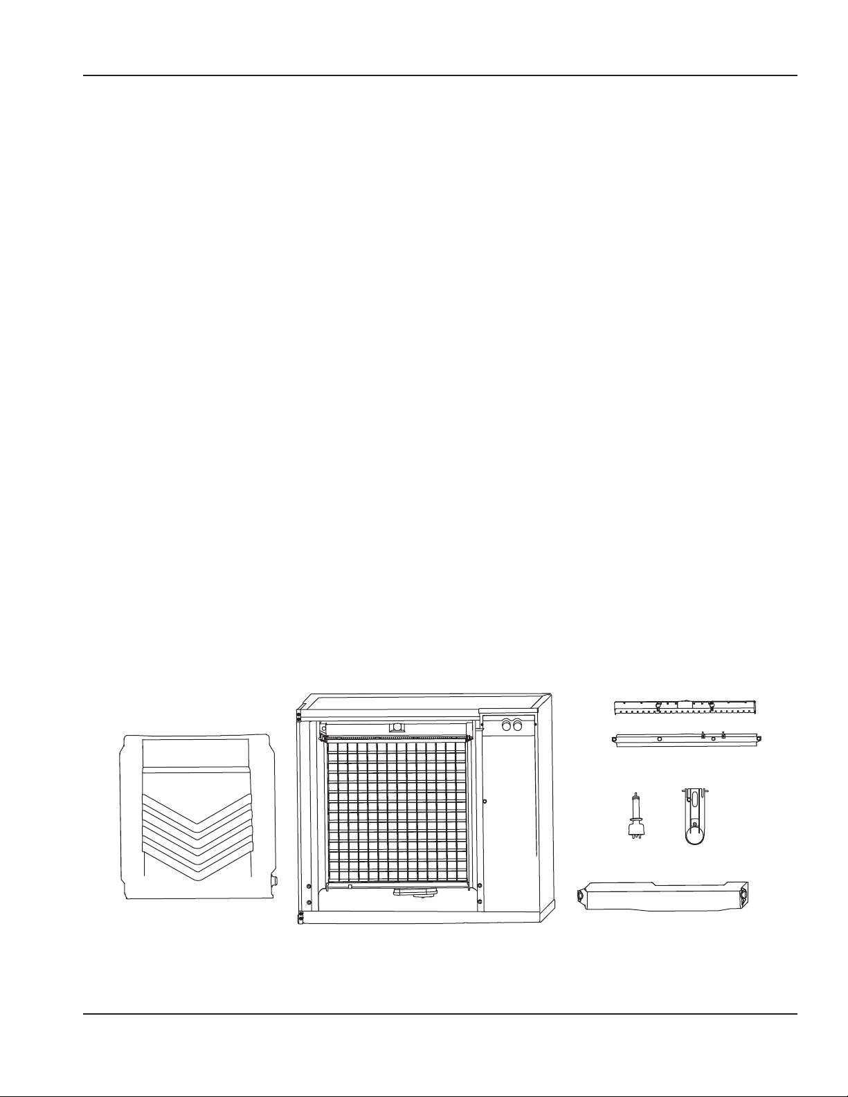
Part Number: 000014141 Rev 03 2/18 43
Section 4 Maintenance
Parts Removal for Cleaning/Sanitizing
Single evaporator is shown; Each
evaporator will have a distribution tube and
water curtain/damper.
A. Remove the water curtain(s)
• Gently flex the curtain in the center and
remove it from the right side.
• Slide the left pin out.
B. Remove the ice thickness probe
• Compress the hinge pin on the top of the
ice thickness probe.
• Pivot the ice thickness probe to
disengage one pin then the other. The
ice thickness probe can be cleaned at
this point without complete removal. If
complete removal is desired, disconnect
the ice thickness control wiring from the
control board.
C. Remove the water trough
• Depress tabs on right and left side of the
water trough.
• Allow front of water trough to drop as
you pull forward to disengage the rear
pins.
D. Remove the water level probe
• Pull the water level probe straight down
to disengage.
• Lower the water level probe until the
wiring connector is visible.
• Disconnect the wire lead from the water
level probe.
• Remove the water level probe from the
ice machine.
E. Remove the water distribution tube(s)
NOTE: Thumbscrews for the distribution
tube are retained to prevent loss. Loosen
thumbscrews, but do not pull thumbscrews
out of distribution tube.
• Loosen the two outer screws (do not
remove screws completely because
they are retained to prevent loss) and
pull forward on the distribution tube to
release from slip joint.
• Disassemble distribution tube
by loosening the two (2) middle
thumbscrews and dividing the
distribution tube into two pieces.
A
E
D
C
B

44 Part Number: 000014141 Rev 03 2/18
Maintenance Section 4
Preventative Maintenance Cleaning
Procedure
This procedure cleans all components in
the water flow path, and is used to clean
the ice machine between the bi-yearly
cleaning/sanitizing procedure.
Ice machine cleaner is used to remove lime
scale and mineral deposits. Ice machine
sanitizer disinfects and removes algae and
slime.
NOTE: Although not required and
dependent on your installation, removing
the ice machine top cover may allow easier
access.
Step 1 Ice must not be on the evaporator
during the clean/sanitize cycle. Follow one
of the methods below:
• Press the power switch at the end of
a harvest cycle after ice falls from the
evaporator(s).
• Press the power switch and allow the ice
to melt.
Notice
Never use anything to force ice from the
evaporator. Damage may result.
Step 2 Open the front door to access the
evaporator.
Step 3 Press the Clean button and select
“Make ice when complete”. Water will flow
through the water dump valve and down
the drain. Wait approximately 1 minute
until the water trough refills and the display
indicates Add Chemical. Add the proper
amount of ice machine cleaner to the water
trough by pouring between the water
curtain and evaporator, then confirm the
chemical was added.
Model
Amount of
Cleaner
IF0300/IT0420/IT0620
3 oz
(90 ml)
IT0450/IT0500/IF0600
IF0900/IT1200
5 oz
(150 ml)
IBF0620C/IBF0820C
IBT1020C
5 oz
(150 ml)
IF1400C/IT1500/IF1800C
IT1900/IF2100C
9 oz
(265 ml)
Step 4 Close and secure the front door.
The ice machine will automatically start
ice-making after the clean cycle is complete
(approximately 24 minutes).

Part Number: 000014141 Rev 03 2/18 45
Section 4 Maintenance
Cleaning the Air Filter and Condenser
The washable filter on self-contained ice
machines is designed to catch dust, dirt, lint
and grease. Clean the filter once a month
with mild soap and water.
A dirty condenser restricts airflow, resulting
in excessively high operating temperatures.
This reduces ice production and shortens
component life.
n
Warning
Disconnect electric power to the ice
machine at the electric service switch
before cleaning the air filter or the
condenser. The condenser fins are sharp;
Use care when removing or installing the
air filter.
• Clean the condenser at least every six
months.
• Shine a flashlight through the condenser
to check for dirt between the fins.
• Blow compressed air or rinse with water
from the inside out (opposite direction
of airflow).
• If dirt still remains, call a service agent to
clean the condenser.
Removal from Service/Winterization
All Models
1. Clean and sanitize the ice machine.
2. Turn off the water supply, disconnect
and drain the incoming ice-making
water line at the rear of the ice
machine and drain the water trough.
3. Energize the ice machine, wait one
minute for the water inlet valve to
open and blow compressed air in both
the incoming water and the drain
openings in the rear of the ice machine
to remove all water.
WATER-COOLED MODELS ONLY
• Disconnect the incoming water and drain
lines from the water-cooled condenser.
• Insert a large screwdriver between
the bottom spring coils of the water
regulating valve and pry open the Water
Regulating Valve.
• Hold the valve open and blow
compressed air through the condenser
until no water remains.
All Models
4. Press the power switch and disconnect
electrical power at the main
disconnect/circuit breaker.
5. Fill spray bottle with sanitizer and
spray all interior food zone surfaces.
Do not rinse and allow to air dry.
6. Replace all panels.

46 Part Number: 000014141 Rev 03 2/18
Maintenance Section 4
THIS PAGE INTENTIONALLY LEFT BLANK
Part Number: 000014141 Rev 03 2/18 47
Before Calling for Service Checklist
If a problem arises during operation of your ice machine, follow the checklist below before
calling service. Routine adjustments and maintenance procedures are not covered by the
warranty.
Problem Possible Cause To Correct
Ice machine does not
operate.
No electrical power to the ice
machine and/or condensing
unit.
Replace the fuse/reset the
breaker/turn on the main
switch.
High pressure cutout tripping. Clean condenser coil. (See
page 45)
Energy Saver or other field
entered programming is
stopping ice machine.
Reset to factory defaults.
Water curtain off or stuck
open.
Water curtain must be
installed and swinging freely.
Ice machine is not turned on. Press power button, display
must indicate “Making Ice”.
IB Models Only - Dispenser ice
level thermostat is open.
Adjust thermostat to maintain
correct dispenser level.
Ice machine stops, and can
be restarted by pressing
the power switch.
Service Fault feature stopping
the ice machine.
Refer to “Service Faults” on
page 49.
Ice machine does not
release ice or is slow to
harvest.
Ice machine is dirty. Clean and sanitize the ice
machine. (See page 40)
Ice machine is not level. Level the ice machine.
Low air temperature around
ice machine head section.
Air temperature must be at
least 35° (2°C).
Fan cycle control does not de-
energize condenser fan motor.
Call for service.
Water regulating valve
incorrectly adjusted or will not
close.
Check for water at condenser
drain outlet in harvest cycle.
Contact a qualified service
company to adjust/replace
valve if water is present.
Section 5
Troubleshooting
48 Part Number: 000014141 Rev 03 2/18
Troubleshooting Section 5
Problem Possible Cause To Correct
Ice machine does not cycle
into harvest mode.
The six-minute freeze time
lock-in has not expired yet.
Wait for the freeze lock-in to
expire.
Ice thickness probe is dirty. Clean and sanitize the ice
machine. (See page 40)
Ice thickness probe is
disconnected.
Connect the probe to the
control board.
Ice thickness probe is out of
adjustment.
Adjust the ice thickness probe.
(See page 37)
Uneven ice fill (thin at the top
of evaporator).
Verify sufficient water level
in sump trough. Contact a
qualified service company to
check refrigeration system.
Ice quality is poor (soft or
not clear).
Poor incoming water quality. Contact a qualified service
company to test the quality
of the incoming water and
make appropriate filter
recommendations.
Water filtration is poor. Replace the filter.
Ice machine is dirty. Clean and sanitize the ice
machine. (See page 40)
Water dump valve is not
working.
Disassemble and clean the
water dump valve.
Water softener is working
improperly (if applicable).
Repair the water softener.
Ice machine produces
shallow or incomplete
cubes, or the ice fill
pattern on the evaporator
is incomplete.
Ice thickness probe is out of
adjustment.
Adjust the ice thickness probe.
(See page 37)
Water trough level is too low. Check the water level probe
position.
Water inlet valve filter screen
is dirty.
Remove the water inlet valve
and clean the filter screen.
Water filtration is poor. Replace the filter.
Hot incoming water. Connect the ice machine to a
cold water supply. (See page
19)
Water inlet valve is not
working.
Replace the water inlet valve.
Incorrect incoming water
pressure.
Water pressure must be
20 psi - 80 psi
(140 kPa - 550 kPa).
Ice machine is not level. Level the ice machine.

Part Number: 000014141 Rev 03 2/18 49
Section 5 Troubleshooting
Problem Possible Cause To Correct
Low ice capacity. Water inlet valve filter screen
is dirty.
Remove the water inlet valve
and clean the filter screen.
Incoming water supply is shut
off.
Open the water service valve.
Water inlet valve stuck open
or leaking.
Press the power button and
turn off the ice machine, if
water continues to enter
water trough, replace the
water inlet valve.
The condenser is dirty. Clean the condenser.
High air temperature entering
condenser.
Refer to air temperature chart
for your model on page 12.
The harvest assist air
compressor is not functioning.
Call for service.
Service Faults
In addition to the standard safety controls,
such as the high pressure cutout, your
Manitowoc ice machine features built-
in service faults which will stop the ice
machine if conditions arise which could
cause a major component failure.
Before calling for service, re-start the ice
machine using the following procedure:
1. Press the power button. The display
reads “Off”. Press the power button
again, and the display reads “Making
Ice”.
A. If a service fault has stopped the
ice machine, it will restart after a
short delay. Proceed to step 2.
B. If the ice machine does not
restart, see “Ice machine does not
operate” on page 47.
2. Allow the ice machine to run to
determine if the condition repeats.
A. If the ice machine stops again, the
condition has repeated. Call for
service.
B. If the ice machine continues to
run, the condition has corrected
itself. Allow the ice machine to
continue running.

50 Part Number: 000014141 Rev 03 2/18
Troubleshooting Section 5
THIS PAGE INTENTIONALLY LEFT BLANK

©2017 Welbilt Inc. except where explicitly stated otherwise. All rights reserved.
Part Number: 000014141 Rev 03 2/18
MANITOWOC ICE
ICE MACHINE DIVISION
2110 SOUTH 26TH STREET
MANITOWOC, WI 54220
800-545-5720
WWW.MANITOWOCICE.COM
Welbilt provides the world’s top chefs, and premier chain operators or growing
independents with industry leading equipment and solutions. Our cutting-
edge designs and lean manufacturing tactics are powered by deep knowledge,
operator insights, and culinary expertise.
All of our products are backed by KitchenCare® – our aftermarket, repair, and
parts service.
CLEVELAND
CONVOTHERM®
DELFIELD®
FITKITCHEN™
FRYMASTER®
GARLAND
KOLPAK®
LINCOLN
MANITOWOC®
MERCO®
MERRYCHEF®
MULTIPLEX®
WWW.WELBILT.COM